novel device for improved diagnosis and monitoring of
TRANSCRIPT

Clemson UniversityTigerPrints
All Theses Theses
5-2017
Novel device for improved diagnosis andmonitoring of rotator cuff injuryBrittany Nicole HallClemson University, [email protected]
Follow this and additional works at: https://tigerprints.clemson.edu/all_theses
This Thesis is brought to you for free and open access by the Theses at TigerPrints. It has been accepted for inclusion in All Theses by an authorizedadministrator of TigerPrints. For more information, please contact [email protected].
Recommended CitationHall, Brittany Nicole, "Novel device for improved diagnosis and monitoring of rotator cuff injury" (2017). All Theses. 2632.https://tigerprints.clemson.edu/all_theses/2632

NOVEL DEVICE FOR IMPROVED DIAGNOSIS AND MONITORING OF ROTATOR CUFF
INJURY
A Thesis Presented to
the Graduate School of Clemson University
In Partial Fulfillment of the Requirements for the Degree
Master of Science Bioengineering
by Brittany Nicole Hall
August 2014
Accepted by: Dr. David Kwartowitz, Committee Chair
Dr. Charles Thigpen Dr. Delphine Dean

ii
ABSTRACT
Rotator cuff disease impacts approximately over 50% of the population above the age of
60, causing pain and ultimately possible loss of shoulder function. The rotator cuff is
composed of muscles and tendons that work in tandem to support the shoulder and aid in
the movement of the arm. History of trauma and increased age can lead to a rotator cuff
tear, which can range in severity from a partial-thickness tear to a full-thickness, total
rupture. Currently, diagnostic techniques for rotator cuff disease are based on physical
assessment, detailed patient history, and medical imaging, primarily X-ray, MRI and
ultrasonography. However, limitations still exist regarding rotator cuff diagnosis and
monitoring. Ultrasound has been shown to have good accuracy in the identification and
measurement of full-thickness and partial-thickness rotator cuff tears. Quantitative data
regarding rotator cuff tears is not as readily available as the qualitative data provided by
the aforementioned techniques. The device designed through this study improves the
method of transduction and the analysis of in situ measurement of rotator cuff
biomechanics. Improvements include the ability of the clinician to apply a uniform force
to the underlying musculotendentious tissues while simultaneously obtaining an
ultrasound image and the addition of Bluetooth for ease of data transfer. Preliminary
studies were performed with the device on both post-operative and healthy patients, in
which the stress and strain experienced by the rotator cuff tissue was analyzed. This
device will ultimately aid in developing a more thorough predictive diagnostic model for
the treatment of rotator cuff disease and aid clinicians in choosing the best treatment
option for patients.

iii
ACKNOWLEDGMENTS
I would like to thank, first and foremost, my committee chair, David Kwartowitz,
for allowing me the opportunity to work on this project and providing me with guidance
throughout it. I would also like to thank my other committee members Chuck Thigpen
and Delphine Dean for providing constant assistance and guidance. I would also like to
say a big thank you to Anup Pillai as well as the rest of the CUTTERS lab members . I
would also like to thank my parents for supporting and encouraging me throughout the
past year during my Master’s studies and research. Lastly, I would like to thank my
friends for their support and encouragement. I would also like to the SCMedTrans Tech
funding for financial assistance.

iv
TABLE OF CONTENTS
Page
TITLE PAGE .................................................................................................................... i ABSTRACT .................................................................................................................... ii ACKNOWLEDGMENTS .............................................................................................. iii LIST OF TABLES .......................................................................................................... v LIST OF FIGURES ........................................................................................................ vi CHAPTER I. INRODUCTION ........................................................................................... 1 Overview ................................................................................................. 1 Anatomy .................................................................................................. 1 Rotator Cuff Tears ................................................................................... 5 Existing Diagnostic Methods .................................................................. 7 Current Diagnostic Limitations ............................................................. 10 II. DEVICE DESIGN AND SOFTWARE ....................................................... 13 Device Design ....................................................................................... 13 Software and Functioning ...................................................................... 18 III. PATIENT DATA ........................................................................................ 23 Methods ................................................................................................. 23 Preliminary Study Results ..................................................................... 25 IV. CONCLUSIONS AND DISCUSSION ....................................................... 33 Conclusions ........................................................................................... 33 Future Work ........................................................................................... 34 REFERENCES .............................................................................................................. 35

v
LIST OF TABLES
Table Page 3.1 Statistical Analysis of Stain, Stress, and Stiffness ...................................... 27 3.2 External Rotation and Functional Outcome for Post-op patients………….28

vi
LIST OF FIGURES
Figure Page 1.1 Glenohumeral Joint Surface Model ............................................................... 2 1.2 Anterior View, Rotator Cuff Anatomy .......................................................... 3 1.3 Posterior View, Rotator Cuff Anatomy ......................................................... 3 1.4 Rotator Cuff Physical Examination ............................................................... 8 2.1 Internal Component of the Device .............................................................. 15 2.2 Shell of the Device ...................................................................................... 15 2.3 Cross-section of the Shell of the Device ..................................................... 16 2.4 Full Device with Separated Components .................................................... 16 2.5 Fully Assembled Device .............................................................................. 17 2.6 Procedural Block Diagram .......................................................................... 19 2.7 Software Procedural Diagram ..................................................................... 20 3.1 Baseline Length Measurement .................................................................... 24 3.2 Compression Force Measurement ............................................................... 25 3.3 Stress versus Strain Curve: Healthy Patients ............................................... 28 3.4 Stress versus Strain Curve: Post-op Patients ............................................... 28 3.5 Healthy Patients Stiffness ............................................................................ 29 3.6 Post-op Patient Stiffness .............................................................................. 29 3.7 Stress vs. External Rotation for Post-op Patients ........................................ 29 3.8 Strain vs. External Rotation for Post-op Patients ........................................ 29

vii
List of Tables (Continued)
Figure Page 3.9 Stiffness vs. External Rotation for Post-op Patients .................................... 29
1
CHAPTER ONE
INTRODUCTION
Overview
Rotator cuff disease is the most common shoulder problem, with about 20.7-22.1% being
affected by it. 1,2 The largest risk factors for rotator cuff tears include a history of trauma and a
person’s age. 1 The number of those affected by the disease increases with age; over 50% of the
population over the age of 60 is affected by rotator cuff disease.1, 3, 4 Rotator cuff tears have
significant impacts on a patient’s life aside from the pain experienced by the disease, which can
ultimately cause loss of function. The impacts include significant decrease in overall health,
particularly with regards to physical functioning, social functioning, physical health, and
emotional health. 5,6 It has even been suggested that a patient’s quality of life is effected to the
same degree as those with one of five major medical conditions: hypertension, congestive heart
failure, acute myocardial infarction, diabetes mellitus and clinical depression. 5 Although tears
are common in the elderly, they can occur in those under the age of 40 if accompanied by acute
trauma. 7 Of all the patients seen by shoulder surgeons, rotator cuff injuries account for 30%. 8,9
Anatomy
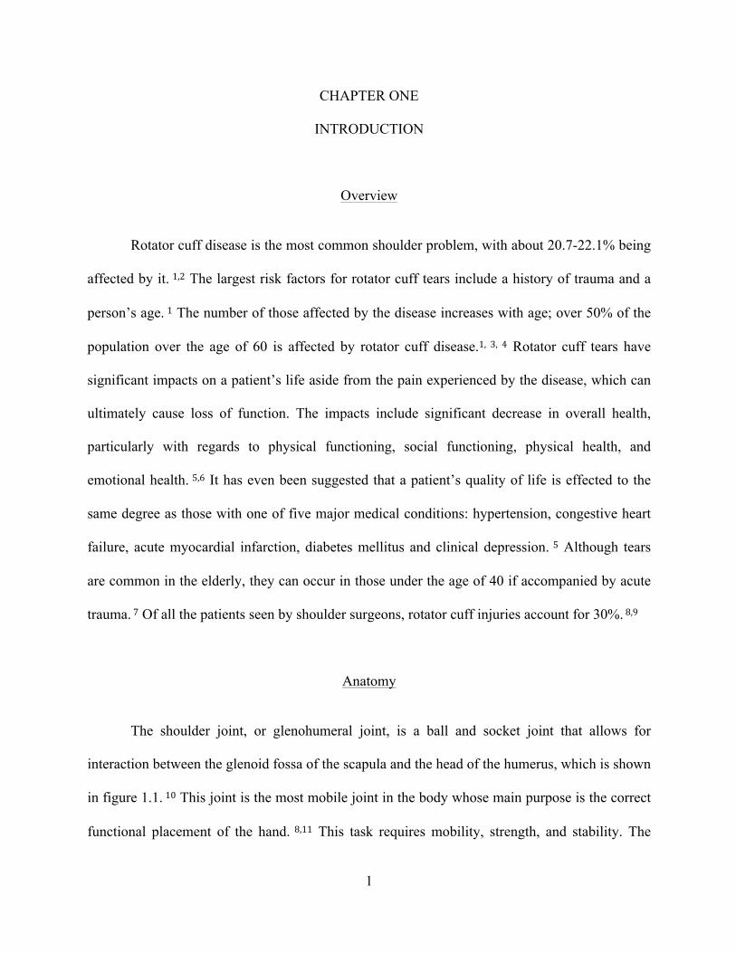
The shoulder joint, or glenohumeral joint, is a ball and socket joint that allows for
interaction between the glenoid fossa of the scapula and the head of the humerus, which is shown
in figure 1.1. 10 This joint is the most mobile joint in the body whose main purpose is the correct
functional placement of the hand. 8,11 This task requires mobility, strength, and stability. The

2
rotator cuff is comprised of four main muscles and their musculotendinous attachments, which
provide the stability of the glenohumeral joint. 8,12
Figure 1.1: Glenohumeral Joint Surface Model
The rotator cuff is comprised of four main muscles: the subscapularis, the supraspinatus,
the infraspinatus, and the teres minor, as shown in figure 1.2 and 1.3. 13 The subscapularis
muscle originates in the scapula and is innervated by the subscapular nerve. 12 It is a large
structure that is flat in shape and is powerful enough to oppose the function of both the
infraspinatus and teres minor muscles posteriorly. 14 The supraspinatus originates in the scapula
and inserts into the greater tuberosity via its tendon. 12 It works in conjunction with the teres
minor, which originates in the scapula as well. The teres minor is innervated by the axillary
nerve and inserts into the greater tuberosity. The infraspinatus originates in the supraspinous

3
fossa and is innervated by the suprascapular nerve. All of the aforementioned muscles end in
tendons that fuse with the fibrous capsule to form the cuff. 14
Fig 1.2: Anterior View, Rotator Cuff Anatomy

4
Fig 1.3: Posterior View, Rotator Cuff Anatomy
During shoulder motion, the muscles of the rotator cuff stabilize the glenohumeral joint.
Contraction of the supraspinatus in conjunction with the deltoid muscle is responsible for
abduction of the arm. 8,15 Supraspinatus activity continues throughout the process of abduction. 15
This upward motion caused by the supraspinatus is opposed by the action of the infraspinatus,
subscapularis, and teres minor, which all depress the humeral head to ensure and maintain
stability of the joint. 8 The muscles of the rotator cuff have varying contributions to the torque
produced during abduction, with 30% being due to the subscapularis, 25% by the supraspinatus,
and 10% by the infraspinatus. 16 The four muscles of the rotator cuff both generate torque and
5
depress the humeral head, allowing for stabilization of the joint. In large rotator cuff tears, this
stabilization is compromised and the humeral head is allowed to migrate. 12
Rotator Cuff Tears
Typically, a rotator cuff tear is the result of degeneration, as a result of shear wear in the
presence of hypovascularity that reduces tendon integrity. 11 An extreme overload event, such as
a significant fall, motor vehicle crash, or shoulder dislocation, can also cause a tear. 8,11
However, degeneration is most frequently the cause of tears as opposed to trauma. 8 The three
stages of rotator cuff disease defined by Neer depict the anatomical changes within the rotator
cuff that lead to the varying degrees of thickness: Stage I tears occur in patients younger than 25
and are typically due to edema and hemorrhage of the bursa and tendon; Stage II tears occur in
patients 25-40 years old and are typically due to tendonitis and fibrosis; Stage III tears occur in
individuals over the age of 40 and involves partial or full-thickness tearing of the cuff. 17
A study of cadaveric models found that of 30.24% of tears found, 11.75% were full-
thickness and 18.49% were partial-thickness. 18 In an autopsy study, the incidence of partial tears
was found to be 28.7%. 19 In smaller tears, increased fibroblast cellularity, increased expression
of leucocytes, and increased expression of vascular markers occur, all which are indicative of
inflammation and healing. However, these traits are seen less often as the size of the tear
increases. 20 In large tears, evidence of edema and degeneration has been seen with little signs of
inflammation and healing, as seen in smaller tears. This suggests that smaller tears have a greater
chance of healing than larger ones due to the presence of anatomical markers associated with
inflammation and healing. 20 It has been demonstrated that 10% of partial-thickness tears fully
heal and 10% will become smaller. However, 53% of partial-thickness tears will propagate, with

6
28% progressing to full-thickness tears. 21 When the progression to a full-thickness tear occurs,
persistent tendon defect can occur if surgical measures are not taken, which can ultimately lead
to detrimental effects in both cells and tissue within the joint. 9 It has been suggested that
supraspinatus involvement always occurs in rotator cuff ruptures. 19 The supraspinatus tendon
becomes thickened and more likely to tear with increasing age. 22
The most common symptoms associated with rotator cuff disease are pain in the
shoulder, moderate to severe weakness, and reduced range of motion. 23 Although some rotator
cuff injuries present debilitating symptoms that significantly alter the quality of life, symptoms
are not always present with the existence of a tear. 2 Only 34.7% of rotator cuff tears are
associated with symptoms, leaving 65.3% of rotator cuff tears to be asymptomatic. 2 The
presence of asymptomatic tears is common, and increases in probability with age. 2,23-‐25
Asymptomatic tears constitute for about half of the tears in people in their 50s and over two-
thirds of those in people over the age of 60. 2 Over half of asymptomatic rotator cuff tears have
been demonstrated to progress to symptomatic in less than three years, during which the tear
increases in size. 25 Overall, asymptomatic tears are twice as likely as symptomatic tears within
the population. 2
Across literature, it is unanimously agreed upon that the likelihood of rotator cuff disease
increases with age. 1,2,4,19,23,24,26 Approximately 30-54% of individuals over the age of 60
experience the pain and debilitation associated with rotator cuff disease. 4,24,26 The prevalence
increases markedly above the age of 80 in which 36.6%-80% of individuals are affected by
rotator cuff disease. 2,4 This prevalence significantly increases every decade, affecting 10.7% of
those in their 50s, 15.2% of those in their 60s, 26.5% of those in their 70s, and 36.6% of those in

7
their 80s, in a particular study. 2 It has been suggested that neither dominance nor gender have
any affect on rotator cuff disease. 4
Although rare, rotator cuff disease can occur in individuals under the age of 40. The
prevalence of rotator cuff tears under the age of 40 is 0-4%. 2,24 This is typically due to acute
trauma caused by impingement and flexibility deficits, strength deficits, or both. 7 This type of
injury is often seen in throwing athletes such as baseball players, rowers, and tennis players.
When torn, it has been observed that increasing rotator cuff tear thickness is correlated
with increased strain in the intact posterior portion and decreased strain in the torn anterior
portion. 27 The stiffness of a torn supraspinatus initially decreases, but quickly increases with
time from the injury, as observed in animal studies where rotator cuff tendons were torn and
observed. 28 The presence of atrophy and fatty infiltration in rotator cuff tears directly correlates
with how repairable a tear is. It has been observed that fatty infiltration and atrophy increase
within a 48-month period and within one year of rotator cuff tendon repair, atrophy improves
partially while fatty infiltration does not recover. 29,30
With regards to medical costs, workers compensation, and decreased productivity, it has
been suggested that rotator cuff disease accounts for $3-5 billion a year. 31,32 Second to back
pain, rotator cuff injuries are one of the main cases of lost work time in manual laborers. 33
Rotator cuff tendonitis is common among those who work in heavy labor-intensive fields. For
example, approximately 18.3% of shipyard welders and 16.2% of plate workers experience the
pain associated with rotator cuff disease, which has been attributed to the heavy hand tool use in
such fields. This excessive muscle maneuver increases strain in the supraspinatus and the
infraspinatus. This strain on the supraspinatus that occurs in overhead lifting significantly
contributes to the shoulder disabilities often seen in individuals in theses professions. 33

8
Existing Diagnostic Methods
Currently the diagnosis of rotator cuff disease includes patient history analysis, pain
assessment, a physical examination, and testing utilizing imaging modalities. During the physical
examination, a physician assesses for signs of impingement, which includes applying various
forces, varying from 5-10 pounds, to the joint at varying angles as well as analyzing the range of
motion. Force is applied during downward pushes to examine if pain exists at this point and
disappears when the force and push is removed, shown in figure 1.4. 34 With rotator cuff disease,
pain is often exacerbated with overhead movements, which is another symptom clinicians look
for during the physical examination. 12 Although patient history and a physical examination are
often the first steps performed during rotator cuff diagnosis, it has been suggested that there is a
lack of a clinically relevant diagnosis utilizing the two. 35 If the physical examination, pain
assessment, and patient history point towards a positive diagnosis, imaging modalities are
utilized to further differentially diagnose the injury.
Figure 1.4: Rotator Cuff Physical Examination

9
Magnetic resonance imaging (MRI) is often used in the diagnosis of rotator cuff injuries
for patients considering surgery. MRI has excellent soft tissue contrast and does not use ionizing
radiation, making it a good candidate for the diagnosis of injuries in the shoulder joint. 36 This
technique not only limits the analysis of real-time results, but is also costly, time-consuming, and
requires a large space for the equipment. It is the high-cost and time consumption associated with
MRI that often makes it an impractical diagnostic device for rotator cuff injuries. 22 It has also
been observed that MRI does not have the ability to differentiate between partial and full-
thickness tears nor incomplete tears. This modality also does not have the ability to differentiate
between the different surfaces at which a tear is located. 37
The other imaging modality used in the diagnosis of rotator cuff tears is ultrasound.
Ultrasound is an attractive diagnostic device for several reasons. Obtaining images with
ultrasound is a relatively quick process that is safe and noninvasive. It is also not limited by
patient size, cooperation, or positioning and can be used bedside. It is also readily available. 38
Ultrasound allows for real-time results and has been suggested to be a reliable, timesaving
practice in the diagnosis of rotator cuff tears when performed by a skilled clinician. 39 Studies
have reported varying sensitivity and specificity values for ultrasound, ranging from 96.2-100%
and 95.4-97%, respectively, for full-thickness tears. 39,40 The estimation of tear size is more
accurate for larger tears than smaller tears with ultrasound, with 96.5% of larger tears being
correctly estimated and 91.6% of smaller tears being correctly estimated. 39 When used to
diagnose partial-thickness and full-thickness tears, ultrasound detects 80% and 90%,
respectively, of total tears, correctly showing the site of the tear in every patient. 41
In the argument of whether ultrasound or MRI is the best diagnostic modality for rotator
cuff disease, various data and opinions exist. Some argue that ultrasound is not as accurate as
10
MRI in the diagnosis of rotator cuff tears. 42 However, many studies suggest that ultrasound and
MRI are comparable for the diagnosis of rotator cuff disease, and are essentially equal diagnostic
tools. 43-‐45 It has also been observed that the sensitivity of ultrasound diagnosis (93.4%) is greater
than MRI diagnosis (87.5%). 46 Due to the fact that ultrasound has a high sensitivity and
specificity, is economic, and fast, it is the preferred diagnostic method. 45,46 Ultrasound also
performs better in the detection of partial-thickness tears. 47
Current Diagnostic Limitations
Although the aforementioned methods have the ability to correctly diagnose rotator cuff
disease, there is a lack of thorough, biomechanical data with each method. Although qualitative
data is available, limitations exist with the aforementioned tests that prevent clinicians from
obtaining both qualitative and quantitative data to aid in the diagnosis. This indirect assessment
also prevents diagnoses from being standardized. Various clinicians interpret the qualitative data
differently provided by the techniques currently used, causing diagnoses to be very subjective. In
short, there is little scientific basis upon which treatment decisions are currently made. 38 The
availability of a quantified standardized procedure would allow for a complete and accurate
comparison of tears between various patients as well as tears before and after treatment or
surgery in the same patient. The ability to quantify rotator cuff tears is something that can
overcome the limitations currently encountered. 38
As previously stated, little research has been performed in the area of quantifying the
active rotator cuff tendon. However, interest in this area is developing due to the relatively high
rate of failed rotator cuff repairs. 38 Bull, Reilly, et al described the use of arthroscopically
insertable force probes to study the rotator cuff in vivo. 48,49 These force sensors were
11
arthroscopically implanted into the subscapularis tendon, after which forces were applied during
active tendon movement and measured. The results of the subscapularis tendon loading
suggested that the subscapularis is capable of producing up to 250 N of force during maximum
internal rotation of the shoulder. 48 Kim et al also described an in vivo supraspinatus analysis
which documented the strain of the superficial, middle, and deep regions of the supraspinatus
tendon. 50 The displacement and strain was measured during isotonic and isometric shoulder
movement, in which a greater displacement was observed in the superficial region than the deep
region during isometric motion, 1.66mm and 0.61mm respectively. During isotonic motion, the
displacement was greater in the deep region than the superficial region, 1.61mm and 0.70mm
respectively. 50
Studies have been performed using an ultrasound in vivo approach on the Achilles tendon
51-‐53, tibialis anterior tendon 54,55, and patellar tendon. 56,57 However, such an approach has not
been extensively studied in the rotator cuff. The measurement of in vivo tendon function via
ultrasound utilization is a method that shows great promise for the rotator cuff tendon, especially
when combined with force and stress deformation estimations. 38 Tendon stiffness can be a
predicative model for rotator cuff disease and can be measured through ultrasound utilization due
to the fact that ultrasound can obtain images before, during, and after compression of the tendon.
Therefore, tissue strain can be measured utilizing the ultrasound probe to administer force. 58
This force will allow for the collection of quantitative data that can then be paired with the
qualitative data obtained from ultrasound imaging to produce a more thorough, comprehensive
diagnosis of rotator cuff injury. With this method, force sensors do not have to be physical
implanted, there are no known side effects, and real-time, dynamic images can be obtained and
paired with quantitative data. This will allow for a more objective judgment of postoperative
12
rotator cuff healing through mechanical data that is currently not available. This will also allow
the use of tendon biomechanics to serve as an indicator of normal versus compromised tendon
function, allowing for a standardized diagnosis to exist among clinicians regarding rotator cuff
disease. In this study, an apparatus was developed that utilizes force measurements and
ultrasound images to obtain, compile, and process raw data to yield diagnostically relevant data
indicative of rotator cuff tendon mechanics. This device was then tested on patients with normal
and compromised rotator cuff tendons to obtain preliminary diagnostic data regarding force
measurements relating to rotator cuff disease.

13
CHAPTER TWO
DEVICE DESIGN AND SOFTWARE
Device Design
The original idea for the device was to have a moving component that allowed for the
measurement of a baseline force and compression force, ergonomic. Earlier iterations of this
device that were designed were too bulky to allow for the incorporation of the force sensors
while also being adaptable to different types of ultrasound probes. Due to the requirement that
the device needed to fit a variety of ultrasound probes, the smallest component of the device
needed to be big enough to fit the largest, most common probe, the HFL50x 15-6 MHz
transducer. Hence, the final iteration of the device was created and is comprised of two parts, an
internal component and a shell.
The internal piece has two parts that fit together, as shown in figure 2.1. These two parts
are attached onto an ultrasound probe that is pushed into the patient’s shoulder and, therefore,
rotator cuff tissue. This part is what is utilized, in conjunction with the ultrasound probe, to
administer the force that is measured and reported. The internal piece is designed to be universal
for all ultrasound probes, which is achieved by having several different options of the internal
piece. All of these pieces have the same exterior design, so that they are all compatible with the
same shell, with various foam patterns on the interior to compensate for the different probe sizes
available on the market. The transducer is placed within the long axis of the infraspinatus muscle
at the level of the posterior glenohumeral joint line, inferior to the spine of the scapula. Each
ultrasound image is centered along the spinoglenoid notch, where standardized measurements are
calculated.

14
The shell, which is shown in figure 2.2, is comprised of two parts. The cross-section of
the shell, which is one of the two pieces, is shown in figure 2.3. Two force sensors are placed on
the bottom of these parts, which then attach over the internal component, as shown in figure 2.4.
Therefore, when fully assembled, the shell contains force sensors that push against the internal
component when applied to rotator cuff tissue, as shown in figure 2.5. This allows for the sensors
to read the force applied to the tissue by the clinician. The top of the shell was designed with a
curved surface to fit the contour of the human hand, making the use of this device more
comfortable for the end user. This curvature also allows the device to be fully functional with the
use of only one hand, much like the use of an ultrasound probe. This aspect of the device
mitigates a learning curve with the end user, due to the fact that its handling and use is much like
that of the ultrasound probe itself.

15
Figure 2.1: Internal Component of the Device
Figure 2.2: Shell of the Device

16
Figure 2.3: Cross-section of the Shell of the Device
Figure 2.4: Full Device with Separated Components

17
Figure 2.5: Fully Assembled Device
This design is more ergonomic and reliable as compared to the first iteration54.
The first iteration of the apparatus had some drawbacks, the most significant being the
force measurements from the sensor were not uniform. The old iteration used flex sensor
to measure force, which is a less reliable way of measuring force than the compression
load cell sensors used in this device. Also, the flex sensors have a shorter life span than
those used in this device and are more prone to wear. This led to the clinician having to
18
repeat the procedure several times to obtain acceptable readings. The improved device
also incorporates the hardware of the device, the battery and Arduino board, within the
device, whereas the old device had a box external to the device itself containing the
hardware. The Fio V3 Arduino board used in this device is also much smaller in size than
the Arduino Uno board used in the old device. The previous iteration also utilized
springs, which are susceptible to wear and corrosion. This improved device is comprised
of two parts, where one part is able to move over the other. This aspect decreases the
likelihood of the wear and tear that existed with the previous iteration. The large springs
in the previous device design also required the use of both hands to compress the device,
and allow for the compression force measurement. This meant that the device was not
held like the ultrasound probe itself, and created a learning curve for the clinician using
it. The new design is smaller and only requires one hand for use and is gripped in a
similar manner as an ultrasound probe.
Software and Functioning
The system within the device allows for the measurement of force measurements,
both at a baseline value and a compression value, after which the difference is analyzed.
The system does the following: (i) obtains both baseline and force measurements when
attached to the probe that is used to push into the tissue; (ii) difference between the
baseline and force is calculated then utilized to obtain stress; (iii) the length of the tissue
at the baseline and compression force are measured on ultrasound images; (iv) the

19
difference in length between the baseline and force lengths is calculated and utilized to
obtain strain; and (v) Young’s Modulus is calculated using the calculated stress and
strain. This process is outlined in Figure 2.6.
Figure 2.6: Procedural Block Diagram
Step i listed above can further be explained with respect to how the device allows
for the force measurement to be obtained and read. This is displayed in Figure 2.7. First,
two compression load cells force transducers collect the data. When the device is used,
these sensors, which are attached to the shell, push onto the exterior surface of the

20
internal piece. The sensors report the voltage associated with the amount of force the
clinician applies with the aid of the transducer to the patients shoulder.
Figure 2.7: Software Procedural Diagram
The obtained voltages are then transferred to a laptop via the Bluetooth present on
the Fio V3 Arduino board fitted on the device 59. The previous iteration of this device
used an USB cable to transfer the obtained measurement to a computer, which is
something that needed to be improved upon. With respect to the earlier iteration,

21
clinicians complained about the how difficult it was to use a device that was hooked up to
a computer via a cable along with the transducer that the device surrounds also being
hooked up to a separate system. This prevented ease of use, and it was essentially a
nuisance for clinicians to try to use a device wired to several different machines.
Therefore, with this device, Bluetooth was incorporated into the hardware to prevent this
annoyance and allow the clinician to use the device more easily. With the Bluetooth, the
device is free of cables, and does not have to be attached to a computer. The laptop that
displays the collected data can be placed anywhere in the near vicinity, allowing the
clinician to used the improved device almost like an ultrasound transducer.
After the recorded voltage is transferred to a laptop, it is entered into a Matlab
program that was created to convert the voltage to the corresponding force measurement.
Once the sensors were incorporated into the device, calibrations were performed to obtain
the forces that correspond to the voltages read by the sensors. Various weights were
loaded onto the device and the corresponding output voltages were recorded. For each
weight, two voltages were recorded, one for each of the sensors. Several trials were
performed, and the voltages for each weight were averaged as well as for the two sensors.
A linear interpolation was then performed to ensure each possible voltage output had a
corresponding force measurement. A look-up table was created with all possible voltage
outputs and the corresponding force measurements, which was incorporated into a Matlab
program that allows the clinician to enter the voltage displayed from the device to obtain
the correct force measurement. Ultimately, this program takes the voltage input and gives

22
the corresponding calibrated force using the look up table. If the voltage entered is not
available in the table, the program interpolates linearly to find the corresponding force.

23
CHAPTER THREE
PATIENT DATA
Methods
A clinical study was performed to ensure the proper functioning of the device as
well as to obtain preliminary results. The device was used on a total of eight patients, four
healthy patients and four post-operative patients. The post-operative patients had rotator
cuff repairs performed approximately two years prior to testing. The healthy patients
were in their mid-20s and had no previous rotator cuff or shoulder injuries. For the post-
operative patients, three trials of both the involved, the shoulder the surgery was
performed on, and non-involved shoulder were performed. For the healthy patients, three
trials of both the dominant and non-dominant shoulder were performed.
For each trial, the device was attached at a Sonosite HFL50 transducer and
attached to a Sonosite ultrasound system. The device was then used to obtain a baseline
image and the corresponding force measurement, which was done by gently touching the
probe to the patient’s skin. The clinician then applied as much force as possible to the
tendon and a force measurement was recorded while simultaneously obtaining an
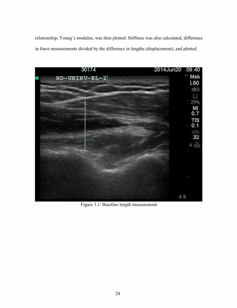
ultrasound image. OsiriX was then used to measure the length of the tendon in both the
baseline and force images for each trial, as shown in figures 3.1 and 3.2. The strain was
calculated by dividing the difference between the baseline and force lengths (Δl) by the
baseline length (l). Stress was calculated by dividing the difference of the baseline and
compression force measurements by the area of the transducer. The stress and strain
24
relationship, Young’s modulus, was then plotted. Stiffness was also calculated, difference
in force measurements divided by the difference in lengths (displacement), and plotted.
Figure 3.1: Baseline length measurement

25
Figure 3.2: Compression force length measurement
Preliminary Study Results
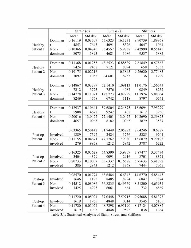
Once data was obtained, the stress, strain, and stiffness for each trial was
calculated. The mean and standard deviation of each was calculated, as shown in table
3.1. The stress and strain were plotted to produce a graph, Young’s Modulus. Two
separate graphs were produced: one for the healthy patients (dominant versus non-
dominant) and one for post-operative patients (involved versus non-involved), as shown
in figures 3.3 and 3.4. The calculated stiffness values were also graphed, shown in figures

26
3.5 and 3.6. For post-op patients, the external rotation and functional outcome scores,
which range from 0-100 with 100 being fully functional, were recorded, as shown in table
3.2. The stress, strain, and stiffness for the post-op patients were then each graphed
against the external rotation, as shown in figures 3.7-3.9.
27
Strain (σ) Stress (ε) Stiffness Mean Std dev Mean Std dev Mean Std dev
Healthy patient 1
Dominant
0.161194853
0.037077643
55.63234091
16.12318326
8.907394047
1.899681064
Non-dominant
0.103668075
0.047405893
35.45574681
15.97381086
9.429909537
0.551455885
Healthy Patient 2
Dominant
0.133685424
0.012559438
48.25237121
6.885398094
7.61849658
0.578635833
Non-dominant
0.191757092
0.022161055 64.601
10.58438253
9.26620136
2.774831299
Healthy Patient 3
Dominant
0.148677212
0.032973723
52.14107576
1.091134087
11.01760849
1.565438252
Non-dominant
0.147788249
0.110714768
122.7736742
4.822891118
11.19248797
5.880640741
Healthy Patient 4
Dominant
0.129375908
0.106414672
59.68049242
8.24875402
16.60941612
7.952793956
Non-dominant
0.200164657
13.04270965
77.14018182
13.04270965
10.26907879
2.598233537
Post-op Patient 1
Involved 0.63365
1889 0.50142
7597 31.7449
2424 2.05273
1756 7.64246
5325 10.6887
9201 Non-involved
0.11155279
0.046719958
47.77621212
17.90305942
15.68793787
9.291936222
Post-op Patient 2
Involved 0.16325
3404 0.03628
4379 64.8390
9091 15.9809
2916 7.87477
8701 3.37474
8371 Non-involved
0.20733386
0.100372843
35.63371212
8.165781368
5.756337444
5.413927065
Post-op Patient 3
Involved 0.08570
1646 0.01774
1195 68.6484
8485 16.6343
8794 14.6770
6847 5.85445
7874 Non-involved
0.145123425
0.080864795
56.82356061
0.49559664
8.51200732
4.659346869
Post-op Patient 4
Involved 0.11720
1619 0.05024
1965 37.0448
4848 7.59715
0314 9.95088
3545 5.81373
5105 Non-involved
0.117201619
0.050241965
48.72984848
6.951909595
8.17124838
4.078871634
Table 3.1: Statistical Analysis of Stain, Stress, and Stiffness

28
External Rotation
Functional Outcome Score
Patient 1 Involved 10.9 96 Non-
involved 13.15
Patient 2 Involved 21.4 91 Non-
involved 21.45
Patient 3 Involved 20.65 96 Non-
involved 18.55
Patient 4 Involved 11.65 93 Non-
involved 11.8
Table 3.2: External Rotation and Functional Outcome for Post-op patients
Figure 3.3: Stress versus Strain Curve: Healthy Patients

29
Figure 3.4: Stress versus Strain Curve: Post-operative Patients
Figure 3.5: Healthy Patient Stiffness
30
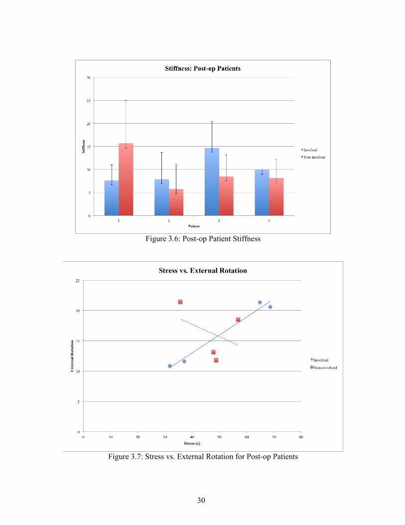
Figure 3.6: Post-op Patient Stiffness
Figure 3.7: Stress vs. External Rotation for Post-op Patients

31
Figure 3.8: Strain vs. External Rotation for Post-op Patients
Figure 3.9: Stiffness vs External Rotation for Post-op Patients

32
For the healthy patients, when the dominant rotator cuff is under stress, the strain
experienced by the tissue does not change. When the non-dominant rotator cuff is under
stress, the strain experienced by the tissue increases, as shown in figure 3.3. For post-
operative patients, an decrease in the strain experienced by the tissue was observed when
the rotator cuff was put under stress in the involved and non-involved shoulder.
In the healthy patient sample, three patients had greater stiffness in their non-
dominant shoulder, while the other had greater stiffness in their dominant. The one
patient who had greater stiffness in the dominant shoulder was an overhead athlete, which
could attribute to this difference. In the post-operative patients sample, three patients
exhibited greater stiffness in their involved shoulder, while one patient exhibited greater
stiffness in their non-involved.
For post-operative patients, when stress was compared to external rotation,
increased external rotation was observed as stress increased in the involved shoulder,
whereas decreased external rotation was seen when stress increased in the non-involved
arm, as seen in figure 3.9. When compared to strain, decreased external rotation was
observed as strain increased in the involved shoulder and increased external rotation was
seen in the non-involved shoulder as strain increased, as seen in figure 3.8. With regards
to stiffness, in the involved shoulder, increased external rotation was seen when stiffness
increased. In the non-involved shoulder, deceased external rotation was observed when
stiffness increased, as seen in figure 3.9.

33
CHAPTER FOUR
CONCLUSIONS AND DISCUSSION
Conclusion
The device produced is a significant improvement upon the previous iteration by
improving several of the issues with the first iteration of the device. The issue of non-
uniform force measurements was improved by incorporating a compression load cell
sensor into the device, rather than the flex sensors used in the old device. This device is
also smaller and lighter than the previous iteration, and is designed to better fit the
contour of the human hand. This new design mitigates the learning curve involved in the
use of the device that was experienced with the first iteration. This device also improves
upon one of the complaints from clinicians about the previous iteration: the cables. By
incorporating Bluetooth into the device, it does not have to be physically attached to a
computer, allowing clinicians to use it more easily.
The study performed with the device not only provided preliminary results
regarding the stress and strain experienced by the rotator cuff tissue in various patients,
but also served to validate the utility of the device. The device was not only easy to use,
but also produced conclusive results. An increase in the strain experienced by the tissue
was observed as stress was applied in both the non-dominant shoulder in healthy patients
and the involved shoulder in post-operative patients. Changes in the strain experienced by
the tissue on the dominant side of healthy patients were not observed as stress was

34
applied. However, when stress was applied to the non-involved side of post-operative
patients, a decreased amount of strain was observed.
Future Work
Although this device is a significant improvement upon the previous iteration,
both in design and functioning, there is still room for improvements. Future plans include
having a push button on the device that would allow for force data to be obtained in
conjunction with the ultrasound image, to ensure both the quantitative data and
qualitative images are obtained simultaneously with little effort. Ultimately, the goal with
this device would be to record a video from the ultrasound, rather than just an image, in
which the force measurements can be captured continuously. This will allow for the
production of a stress versus strain curve, rather than just one value, in conjunction with a
video of the compression of the tissue upon the administration of the force. This will
allow for an even more complete diagnosis and monitoring of the injury.
Further work with this device can also be directed towards its use in anatomical
areas other than the rotator cuff. For example, this device could be used on the Achilles
tendon to aid in the diagnosis and monitoring of Achilles injuries, allowing for a more
complete diagnosis than currently available. The device could also be used in the
veterinary market. There are less diagnostic devices available for the animal model than
the human model, and this device could be utilized to produce a more complete diagnosis
for a range of injuries similar to those in humans.

35
WORKS CITED
1. Yamamoto A, Takagishi K, Osawa T, et al. Prevalence and risk factors of a rotator cuff tear in
the general population. J Shoulder Elbow Surg. 2010;19(1):116-120. doi:
10.1016/j.jse.2009.04.006 [doi].
2. Minagawa H, Yamamoto N, Abe H, et al. Prevalence of symptomatic and asymptomatic
rotator cuff tears in the general population: From mass-screening in one village. J Orthop.
2013;10(1):8-12. doi: 10.1016/j.jor.2013.01.008 [doi].
3. Bartolozzi A, Andreychik D, Ahmad S. Determinants of outcome in the treatment of rotator
cuff disease. Clin Orthop Relat Res. 1994;(308)(308):90-97.
4. Milgrom C, Schaffler M, Gilbert S, van Holsbeeck M. Rotator-cuff changes in asymptomatic
adults. the effect of age, hand dominance and gender. J Bone Joint Surg Br. 1995;77(2):296-298.
5. Gartsman GM, Brinker MR, Khan M, Karahan M. Self-assessment of general health status in
patients with five common shoulder conditions. J Shoulder Elbow Surg. 1998;7(3):228-237.
6. Smith KL, Harryman DT,2nd, Antoniou J, Campbell B, Sidles JA, Matsen FA,3rd. A
prospective, multipractice study of shoulder function and health status in patients with
documented rotator cuff tears. J Shoulder Elbow Surg. 2000;9(5):395-402. doi: S1058-
2746(00)04373-1 [pii].
7. Bytomski JR, Black D. Conservative treatment of rotator cuff injuries. J Surg Orthop Adv.
2006;15(3):126-131. doi: 15-3-1.pdf?T=open_article,943072 [pii].

36
8. MacDermid JC, Holtby R, Razmjou H, Bryant D, JOINTS Canada. All-arthroscopic versus
mini-open repair of small or moderate-sized rotator cuff tears: A protocol for a randomized trial
[NCT00128076. BMC Musculoskelet Disord. 2006;7:25. doi: 1471-2474-7-25 [pii].
9. Derwin KA, Baker AR, Iannotti JP, McCarron JA. Preclinical models for translating
regenerative medicine therapies for rotator cuff repair. Tissue Eng Part B Rev. 2010;16(1):21-30.
doi: 10.1089/ten.TEB.2009.0209 [doi].
10. Massimini DF, Boyer PJ, Papannagari R, Gill TJ, Warner JP, Li G. In-vivo glenohumeral
translation and ligament elongation during abduction and abduction with internal and external
rotation. J Orthop Surg Res. 2012;7:29-799X-7-29. doi: 10.1186/1749-799X-7-29 [doi].
11. Quilllen D, Wuchner M, Hatch R. Acute shoulder injuries. American Family Physician.
2004;70(10):1947-1954.
12. Fongeime A, Buss D, & Rolnick S. Management of shoulder impingement syndrome and
rotator cuff tears. Am Fam Physician. 1998;57(4):667-674.
13. Blum K, Chen AL, Chen TJ, et al. Repetitive H-wave device stimulation and program induces
significant increases in the range of motion of post operative rotator cuff reconstruction in a
double-blinded randomized placebo controlled human study. BMC Musculoskelet Disord.
2009;10:132-2474-10-132. doi: 10.1186/1471-2474-10-132 [doi].
14. DEPALMA AF. Surgical anatomy of the rotator cuff and the natural history of degenerative
periarthritis. Surg Clin North Am. 1963;43:1507-1520.

37
15. Post M, Silver R, Singh M. Rotator cuff tear: Diagnosis and treatment. Clinical orthopaedics
and related research. 1983;173:78-91.
16. Escamilla RF, Yamashiro K, Paulos L, Andrews JR. Shoulder muscle activity and function in
common shoulder rehabilitation exercises. Sports Med. 2009;39(8):663-685. doi:
10.2165/00007256-200939080-00004 [doi].
17. Neer CS,2nd. Impingement lesions. Clin Orthop Relat Res. 1983;(173)(173):70-77.
18. Reilly P, Macleod I, Macfarlane R, Windley J, Emery RJ. Dead men and radiologists don't
lie: A review of cadaveric and radiological studies of rotator cuff tear prevalence. Ann R Coll
Surg Engl. 2006;88(2):116-121. doi: 10.1308/003588406X94968 [doi].
19. Jerosch J, Muller T, Castro WH. The incidence of rotator cuff rupture. an anatomic study.
Acta Orthop Belg. 1991;57(2):124-129.
20. Matthews TJ, Hand GC, Rees JL, Athanasou NA, Carr AJ. Pathology of the torn rotator cuff
tendon. reduction in potential for repair as tear size increases. J Bone Joint Surg Br.
2006;88(4):489-495. doi: 88-B/4/489 [pii].
21. Yamanaka K, Matsumoto T. The joint side tear of the rotator cuff. A followup study by
arthrography. Clin Orthop Relat Res. 1994;(304)(304):68-73.
22. Yu TY, Tsai WC, Cheng JW, Yang YM, Liang FC, Chen CH. The effects of aging on
quantitative sonographic features of rotator cuff tendons. J Clin Ultrasound. 2012;40(8):471-478.
doi: 10.1002/jcu.21919 [doi].

38
23. Fuchs S, Chylarecki C, Langenbrinck A. Incidence and symptoms of clinically manifest
rotator cuff lesions. Int J Sports Med. 1999;20(3):201-205. doi: 10.1055/s-2007-971118 [doi].
24. Sher JS, Uribe JW, Posada A, Murphy BJ, Zlatkin MB. Abnormal findings on magnetic
resonance images of asymptomatic shoulders. J Bone Joint Surg Am. 1995;77(1):10-15.
25. Yamaguchi K, Tetro AM, Blam O, Evanoff BA, Teefey SA, Middleton WD. Natural history
of asymptomatic rotator cuff tears: A longitudinal analysis of asymptomatic tears detected
sonographically. J Shoulder Elbow Surg. 2001;10(3):199-203. doi: S1058-2746(01)10756-1 [pii].
26. Lehman C, Cuomo F, Kummer FJ, Zuckerman JD. The incidence of full thickness rotator cuff
tears in a large cadaveric population. Bull Hosp Jt Dis. 1995;54(1):30-31.
27. Yang S, Park H, Flores S, et al. Biomechanical analysis of bursal-sided partial thickness
rotator cuff tears. Journal of Shoulder and Elbow Surgery. 2009;18(3):379-385. doi:
http://dx.doi.org/10.1016/j.jse.2008.12.011.
28. Gimbel JA, Van Kleunen JP, Mehta S, Perry SM, Williams GR, Soslowsky LJ. Supraspinatus
tendon organizational and mechanical properties in a chronic rotator cuff tear animal model. J
Biomech. 2004;37(5):739-749. doi: 10.1016/j.jbiomech.2003.09.019 [doi].
29. Zingg PO, Jost B, Sukthankar A, Buhler M, Pfirrmann CW, Gerber C. Clinical and structural
outcomes of nonoperative management of massive rotator cuff tears. J Bone Joint Surg Am.
2007;89(9):1928-1934. doi: 89/9/1928 [pii].

39
30. Gerber C, Schneeberger AG, Hoppeler H, Meyer DC. Correlation of atrophy and fatty
infiltration on strength and integrity of rotator cuff repairs: A study in thirteen patients. J
Shoulder Elbow Surg. 2007;16(6):691-696. doi: S1058-2746(07)00333-3 [pii].
31. Vitale MA, Vitale MG, Zivin JG, Braman JP, Bigliani LU, Flatow EL. Rotator cuff repair: An
analysis of utility scores and cost-effectiveness. J Shoulder Elbow Surg. 2007;16(2):181-187. doi:
S1058-2746(06)00321-1 [pii].
32. Silverstein B. KJ. Work-related musculoskeletal disorders of the neck, back, and upper
extremity in washington state, 1992-2000. . 2002;40-6-2002.
33. Herberts P, Kadefors R, Hogfors C, Sigholm G. Shoulder pain and heavy manual labor. Clin
Orthop Relat Res. 1984;(191)(191):166-178.
34. Ebell MH. Point of care guides: Diagnosing rotator cuff tears. Am Fam Physician.
2005;71(8):1587.
35. Jain NB, Yamaguchi K. History and physical examination provide little guidance on
diagnosis of rotator cuff tears. Evid Based Med. 2014;19(3):108-2013-101593. Epub 2013 Dec
17. doi: 10.1136/eb-2013-101593 [doi].
36. Farshad-Amacker NA, Jain Palrecha S, Farshad M. The primer for sports medicine
professionals on imaging: The shoulder. Sports Health. 2013;5(1):50-77. doi:
10.1177/1941738112468265 [doi].

40
37. Reinus WR, Shady KL, Mirowitz SA, Totty WG. MR diagnosis of rotator cuff tears of the
shoulder: Value of using T2-weighted fat-saturated images. AJR Am J Roentgenol.
1995;164(6):1451-1455. doi: 10.2214/ajr.164.6.7754891 [doi].
38. Bey MJ, Derwin KA. Measurement of in vivo tendon function. J Shoulder Elbow Surg.
2012;21(2):149-157. doi: 10.1016/j.jse.2011.10.023 [doi].
39. Al-Shawi A, Badge R, Bunker T. The detection of full thickness rotator cuff tears using
ultrasound. J Bone Joint Surg Br. 2008;90(7):889-892. doi: 10.1302/0301-620X.90B7.20481
[doi].
40. Read JW, Perko M. Shoulder ultrasound: Diagnostic accuracy for impingement syndrome,
rotator cuff tear, and biceps tendon pathology. J Shoulder Elbow Surg. 1998;7(3):264-271.
41. Farin PU, Kaukanen E, Jaroma H, Vaatainen U, Miettinen H, Soimakallio S. Site and size of
rotator-cuff tear. findings at ultrasound, double-contrast arthrography, and computed tomography
arthrography with surgical correlation. Invest Radiol. 1996;31(7):387-394.
42. Burk DL,Jr, Karasick D, Kurtz AB, et al. Rotator cuff tears: Prospective comparison of MR
imaging with arthrography, sonography, and surgery. AJR Am J Roentgenol. 1989;153(1):87-92.
doi: 10.2214/ajr.153.1.87 [doi].
43. Swen WA, Jacobs JW, Algra PR, et al. Sonography and magnetic resonance imaging
equivalent for the assessment of full-thickness rotator cuff tears. Arthritis Rheum.
1999;42(10):2231-2238. doi: 10.1002/1529-0131(199910)42:10<2231::AID-ANR27>3.0.CO;2-Z
[doi].

41
44. de Jesus JO, Parker L, Frangos AJ, Nazarian LN. Accuracy of MRI, MR arthrography, and
ultrasound in the diagnosis of rotator cuff tears: A meta-analysis. AJR Am J Roentgenol.
2009;192(6):1701-1707. doi: 10.2214/AJR.08.1241 [doi].
45. Bachmann GF, Melzer C, Heinrichs CM, Mohring B, Rominger MB. Diagnosis of rotator
cuff lesions: Comparison of US and MRI on 38 joint specimens. Eur Radiol. 1997;7(2):192-197.
46. Zhang C, Guo L, An N, Liu GH, Zhu YT, Fan LJ. Application value of high-frequency
ultrasound on the diagnosis of rotator cuff tears. Zhongguo Gu Shang. 2013;26(9):784-786.
47. Rutten MJ, Spaargaren GJ, van Loon T, de Waal Malefijt MC, Kiemeney LA, Jager GJ.
Detection of rotator cuff tears: The value of MRI following ultrasound. Eur Radiol.
2010;20(2):450-457. doi: 10.1007/s00330-009-1561-9 [doi].
48. Bull AM, Reilly P, Wallace AL, Amis AA, Emery RJ. A novel technique to measure active
tendon forces: Application to the subscapularis tendon. Knee Surg Sports Traumatol Arthrosc.
2005;13(2):145-150. doi: 10.1007/s00167-004-0556-y [doi].
49. Reilly P, Bull AM, Amis AA, Wallace AL, Emery RJ. Arthroscopically insertable force
probes in the rotator cuff in vivo. Arthroscopy. 2003;19(2):E8. doi: 10.1053/jars.2003.50050
[doi].
50. Kim YS, Kim JM, Bigliani LU, Kim HJ, Jung HW. In vivo strain analysis of the intact
supraspinatus tendon by ultrasound speckles tracking imaging. J Orthop Res. 2011;29(12):1931-
1937. doi: 10.1002/jor.21470 [doi].

42
51. Arampatzis A, Stafilidis S, DeMonte G, Karamanidis K, Morey-Klapsing G, Bruggemann
GP. Strain and elongation of the human gastrocnemius tendon and aponeurosis during maximal
plantarflexion effort. J Biomech. 2005;38(4):833-841. doi: S0021929004002398 [pii].
52. Arampatzis A, Peper A, Bierbaum S, Albracht K. Plasticity of human achilles tendon
mechanical and morphological properties in response to cyclic strain. J Biomech.
2010;43(16):3073-3079. doi: 10.1016/j.jbiomech.2010.08.014 [doi].
53. Gerus P, Rao G, Berton E. A method to characterize in vivo tendon force-strain relationship
by combining ultrasonography, motion capture and loading rates. J Biomech. 2011;44(12):2333-
2336. doi: 10.1016/j.jbiomech.2011.05.021 [doi].
54. Farron J, Varghese T, Thelen DG. Measurement of tendon strain during muscle twitch
contractions using ultrasound elastography. IEEE Trans Ultrason Ferroelectr Freq Control.
2009;56(1):27-35. doi: 10.1109/TUFFC.2009.1002 [doi].
55. Maganaris CN, Paul JP. Load-elongation characteristics of in vivo human tendon and
aponeurosis. J Exp Biol. 2000;203(Pt 4):751-756.
56. Hansen P, Bojsen-Moller J, Aagaard P, Kjaer M, Magnusson SP. Mechanical properties of
the human patellar tendon, in vivo. Clin Biomech (Bristol, Avon). 2006;21(1):54-58. doi: S0268-
0033(05)00177-4 [pii].
57. O'Brien TD, Reeves ND, Baltzopoulos V, Jones DA, Maganaris CN. Mechanical properties
of the patellar tendon in adults and children. J Biomech. 2010;43(6):1190-1195. doi:
10.1016/j.jbiomech.2009.11.028 [doi].

43
58. Trent E, Bailey L, Meflah F, et al. Assessment and characterization of in situ rotator cuff
biomechanics. Medical Imaging 2013: Biomedical Applications in Molecular, Structural, and
Functional Imaging. 2013;8672.
59. sparkfun. Fio v3- ATmega32U4. https://www.sparkfun.com/products/11520. Accessed 5/30,
2014.