novel inspection system aligns frp and metallic …
TRANSCRIPT

VOLUME 23, ISSUE 3
MAY | JUNE 2017
A S S E T I N T E G R I T Y I N T E L L I G E N C E
NOVEL INSPECTION SYSTEM ALIGNS FRP AND METALLIC ASSET MANAGEMENT APPROACHESGEOFF CLARKSON, CEO and Founder at UTComp, Inc.

2 Inspectioneering Journal MAY | JUNE 2017
NOVEL INSPECTION SYSTEM ALIGNS FRP AND METALLIC ASSET MANAGEMENT APPROACHESBY: GEOFF CLARKSON, CEO and Founder at UTComp, Inc.
INTRODUCTIONAsset management for steel piping and vessels relies on well-es-tablished systematic approaches that have proven effectiveness. Many operators with Fiberglass Reinforced Plastic (FRP) piping and vessels in their facilities desire the same quality of reporting and advice regarding FRP condition as they receive for their steel assets. Ultrasonic inspection techniques for FRP equipment that are both non-destructive and non-intrusive are available to meet that demand, backed by thousands of inspections to provide reli-able asset management information. Owner/operators can now receive inspection reports for FRP that are similar to those for metallic assets, including the measured effects of damage and the remaining structural capacity compared to the new asset, what-ever its age.
This article provides an overview of a systematic inspection approach for FRP that aligns FRP mechanical integrity results with those for metallic mechanical equipment.
SYSTEMATIC MECHANICAL INTEGRITY MANAGEMENTSystematic approaches, coupled with technology, are used by asset managers to understand the mechanical integrity of assets where reliable process containment and structural support are required. In general, the approach provides owner-operators with informa-tion on measurable changes (e.g., thickness) that have occurred from damage to assets. The rates at which the changes occur are normally used to predict remaining service life. Non-destructive examination techniques and inspector certification programs are usually specified, such as by ASME, ASTM or API, to ensure the availability of qualified inspectors, as well as consistent data results. In the case of ultrasonic equipment, many instruments also contain built-in post-processing to provide “on the spot” anal-ysis of the readings. The final step—Analysis of reported data—is usually completed by a Subject Matter Expert who interprets the measurements and other relevant information to recommend repairs or continued operation.
The time interval between these inspections can be set using either Risk Based Inspections [1] where the risk and consequences of failure can be determined, or they can be based on some time interval based on standards or experience with the service.
Table 1 shows an overview of a typical systematic approach that is used for steel assets. For most steel piping and process vessels, this process has proven to be very effective at providing own-er-operators with safe, cost-effective asset management based on quantified results from the inspection and assessment. The sys-tematic approach allows optimization of the costs and scheduling
of repairs and replacements, along with effective management of change. The uniformity of steel throughout its thickness has contributed to the effectiveness of this non-destructive examina-tion (NDE) technique.
The success of this process has allowed it to become part of the foundation of the Mechanical Integrity stage of Process Safety Management.
Table 1. Systematic Asset Management.
Step Description
Example
Reference
Designations
1.Design, manufacture, construct and install in accordance with standards, codes and regulations.
ASME Boiler & Pressure Vessel CodeASME Power Piping Code (B31.1)
2.Determine the expected damage mechanisms and the operating limits (IOWs) for safe operation of the asset.
API RP 571API RP 584
3.
Inspect the asset to determine the amount of damage that has occurred. Repeatable non-destructive and non-intrusive inspection techniques are used when possible.
API 653API 570API 510
4.
Determine rate of change of the damage. Calculate remaining service life.
YES: Repeat Inspection cycle at Step 3 as planned.
NO: Determine Fitness for Service. Step 5.
API 653API 510API 570
5.
Fitness for Service Assessment. This is used determine what changes are required to the equipment and inspections to maintain safe operation. Update remaining service life.
API 579-1/ASME FFS-1
Asset management for FRP piping and vessels has followed a dif-ferent path. Starting from FRP’s earliest usage, it has become clear that FRP has different damage mechanisms and responses to NDE technologies and damage than steels. Also, the engineering and construction of FRP equipment has a number of differences from steel, requiring different materials, skills and techniques throughout the engineering, manufacture, installation, and in-service inspection stages of its lifecycle. A number of consen-sus standards and codes provide somewhat consistent guidance for design, manufacture, construction and installation of FRP assets [2] [3] [4] [5] [6] [7] [8]. For inspection and integrity man-agement of FRP equipment, the existing guidance [9] [10] [11] is widely varied and routinely draws upon subjective assessments.
Some large users of FRP equipment in the chemical processing
MAY | JUNE 2017 Inspectioneering Journal 3
industry have recognized the need to address inspection and integrity management, rather than trying to duplicate the pro-cess used for steel. These large users have also developed in-house Subject Matter Experts and Inspectors for FRP who often fill similar roles for other materials of construction. With very little third-party training available, development of these experts is normally done internally.
Even still, operators with FRP piping and vessels in their facilities need the same quality of reporting and advice regarding FRP con-dition as they receive for their steel assets.
DESIGN, CONSTRUCTION & DAMAGE OF FRPAn understanding of the specific material properties, fabrication or layup processes and the relevant damage mechanisms is nec-essary for any mechanical integrity program. FRP is constructed of two main ingredients—resin and reinforcement fibers. For this article, the discussion deals with glass fiber reinforcements, although other fiber materials can usually be substituted. The resin is used to provide corrosion resistance, make it leak-tight, and bind the fibers. The fibers give strength and increase the stiff-ness of the FRP. Each glass fiber is coated with a sizing chemical to assist with fiber flexibility and improve bonding of the glass to the resin. Layup or orientation of the fibers is also important.
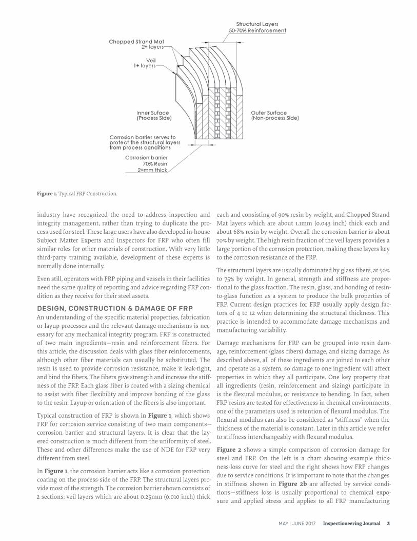
Typical construction of FRP is shown in Figure 1, which shows FRP for corrosion service consisting of two main components—corrosion barrier and structural layers. It is clear that the lay-ered construction is much different from the uniformity of steel. These and other differences make the use of NDE for FRP very different from steel.
In Figure 1, the corrosion barrier acts like a corrosion protection coating on the process-side of the FRP. The structural layers pro-vide most of the strength. The corrosion barrier shown consists of 2 sections; veil layers which are about 0.25mm (0.010 inch) thick
each and consisting of 90% resin by weight, and Chopped Strand Mat layers which are about 1.1mm (0.043 inch) thick each and about 68% resin by weight. Overall the corrosion barrier is about 70% by weight. The high resin fraction of the veil layers provides a large portion of the corrosion protection, making these layers key to the corrosion resistance of the FRP.
The structural layers are usually dominated by glass fibers, at 50% to 75% by weight. In general, strength and stiffness are propor-tional to the glass fraction. The resin, glass, and bonding of resin-to-glass function as a system to produce the bulk properties of FRP. Current design practices for FRP usually apply design fac-tors of 4 to 12 when determining the structural thickness. This practice is intended to accommodate damage mechanisms and manufacturing variability.
Damage mechanisms for FRP can be grouped into resin dam-age, reinforcement (glass fibers) damage, and sizing damage. As described above, all of these ingredients are joined to each other and operate as a system, so damage to one ingredient will affect properties in which they all participate. One key property that all ingredients (resin, reinforcement and sizing) participate in is the flexural modulus, or resistance to bending. In fact, when FRP resins are tested for effectiveness in chemical environments, one of the parameters used is retention of flexural modulus. The flexural modulus can also be considered as “stiffness” when the thickness of the material is constant. Later in this article we refer to stiffness interchangeably with flexural modulus.
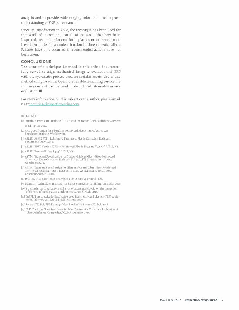
Figure 2 shows a simple comparison of corrosion damage for steel and FRP. On the left is a chart showing example thick-ness-loss curve for steel and the right shows how FRP changes due to service conditions. It is important to note that the changes in stiffness shown in Figure 2b are affected by service condi-tions—stiffness loss is usually proportional to chemical expo-sure and applied stress and applies to all FRP manufacturing
Figure 1. Typical FRP Construction.

4 Inspectioneering Journal MAY | JUNE 2017
methods—hand lay-up, filament winding, and closed molding.
ASSET MANAGEMENT FOR FRP – HISTORICAL APPROACHThe FRP construction method shown in Figure 1 evolved from experience in chemical service to provide corrosion protection to the structural layers from the resin-rich corrosion barrier. In this way, the corrosion barrier acts in similar manner to a coating. This development also expected that inspection and condition monitoring would depend on assessment of the corrosion barrier.
Assessment of the surface of the corrosion barrier deserves some discussion. There are several aspects that must be highlighted. First, the corrosion barrier is only visible from the inside of the process vessel or piping. This means that entry into the space is required, often requiring confined space entry, along with high costs and safety concerns for the personnel who will be entering the vessel. For most piping, this is not possible, so examination of the inner surface may also require destructive sampling and testing—where material is cut from the piping and repairs are required with subsequent hydrotesting.
The second aspect is the criteria for assessing the corrosion bar-rier. Materials Technology Institute (MTI) [9], Swerea KIMAB (KIMAB) [12], TAPPI [11], and Samuelsson [10] have produced docu-ments and training which provide some guidance to help identify features that are used to indicate the condition of the corrosion barrier surface. Although these resources provide useful infor-mation, there remains substantial subjective interpretation about the extent of existing damage and what risk it actually poses to the mechanical integrity of the FRP. In general, conservative approaches are taken with major replacement of the corrosion barrier (re-lining) or asset replacement when corrosion barrier damage is considered to be significant.
Inspection of the corrosion barrier surface involves both the appearance and texture of the surface. The most reliable way to
assess both of these is to contact the surface, so remote visual techniques and photographs are not usually satisfactory. When the Inspector or Subject Matter Expert has reason to believe structural damage has occurred, Acoustic Emission testing [10] may be conducted to detect possible indications of structural damage. Where acoustic emission is not suitable, destructive testing might be completed on material that has been removed.
Visual inspection of FRP has become the standard method for many FRP structures such as storage tanks, piping, process reac-tors, fan blades, and wind turbine blades. In some cases, such as cracks in structural elements, repair or replacement is usually recommended immediately. For asset managers, it is important to relate inspection data to the rate of change of a measurement, and then subsequently determine the remaining service life. There is an absence of published research that relates the visible condition of the corrosion barrier or the results of acoustic emission testing to the mechanical integrity of a FRP asset. These subjective meth-ods have served to prevent failures for many operators, normally by requiring early repair or premature replacement. Currently, there are no consensus standards for inspection or evaluation of fitness-for-service of FRP equipment. There are also no objec-tive codes or standards that identify criteria for determining the remaining life, which can result in widely varying assessments by different inspectors.
If there is any doubt, repairs are often recommended, sometimes costing up to 75% of the asset replacement value. These repairs usually resurface the inner corrosion barrier and do not measur-ably change the mechanical integrity of the FRP. Furthermore, corrosion barrier replacement usually does not provide an “as new” lining, leaving weak links in the FRP system.
NEW NON-DESTRUCTIVE ULTRASONIC ANALYSIS FOR FRP ASSET MANAGEMENTBecause FRP-inspection methods that have been used to date are subjective, operators often may not receive reports that provide
Figure 2. Comparison of Corrosion Damage for Steel & FRP.

MAY | JUNE 2017 Inspectioneering Journal 5
them with quantitative predictions and analyses like they receive for their metallic assets. In my opinion, reports based on corro-sion barrier condition rarely provide long-term guidance for asset replacement or repairs.
As mentioned above, the bending stiffness of FRP will change as a result of both chemical service and stresses. Evaluating reduc-tion in bending stiffness can be extended to provide data that can be used to quantify damage that has occurred. Testing the actual stiffness of FRP that is in-service is both intrusive and destruc-tive; however, new non-destructive, ultrasonic techniques have been developed to provide stiffness information.
When these methods are used on the non-process side (outer) surface of the FRP, information is also provided on the condition and depth of damage to the corrosion barrier, and not only the surface. These systems have already been validated by a number of universities and operators for reproducibility and repeatability.
Figure 3 shows the correlation of stiffness determined from the ultrasonic readings with stiffness determined from destructive tests. Each data point in the figure represents a comparison of non-destructive-to-destructive tests on FRP samples that have come from a number of different service conditions. The dotted line shows the ideal relationship. In the figure, the correlation of the data to the straight line is given by “r”. The value of “r2” is commonly used so that a value greater than 0 is shown. For r2 = 0.88, the correlation is 0.94, which is considered to be very good. The FRP samples ranged in age from new to more than 20 years in service. The values are expressed as percentage of the theoretical stiffness for the FRP that was tested. [13] The results of the test-ing show the total effect from various in-service damage mecha-nisms on the mechanical integrity of the FRP.
Use of the analysis has shown that the results are independent of thickness and the baseline stiffness when new, and can be estab-lished without ultrasonic readings from the new FRP [13]. This
makes it possible to use this new approach on FRP equipment that is currently in service.
The inspection technique uses unique settings and calibration methods with readily available ultrasonic inspection equipment. The procedures and calibration methods are different from com-monly used approaches in ASME (or other) codes and standards, and the technique has been proven as reliable, even when baseline readings from new FRP are unavailable. The technique requires a trained inspector to take ultrasonic readings from the FRP. It is not currently possible for inspectors to determine the results in the field, so the readings and inspection information are then post-processed remotely by Subject Matter Experts to provide the results for the FRP.
Inspection planning is detailed in written procedures to assist inspectors and owners. The inspection process has been designed to accommodate FRP of any age or condition.
External inspection is conducted in parallel following a system-atic approach based on a combination of the guidance in API 510, API 653, API 570 and API 574, along with other items based on extensive experience with FRP damage. In many cases, the results of external inspection can lead to recommendations for immediate repairs to resolve installation defects.
For steel, ultrasonic thickness readings are used to determine corrosion rates so that remaining service life can be calculated based on the rate of change, as illustrated in Figure 2a. Thickness changes directly show changes to the structural capacity of the steel and are used in remaining life calculations. Existing codes and standards provide instructions to determine the minimum allowable thickness, or end of life criteria.
For FRP, Figure 2b shows it can be expected that FRP will expe-rience stiffness loss from service conditions. In some services, thickness loss can also occur. Both of these serve to reduce the structural capacity of the FRP so that remaining service life can
Figure 3. Correlation of Stiffness as Determined by Non-destructive and Destructive Testing.

6 Inspectioneering Journal MAY | JUNE 2017
be calculated in a similar manner to steel, although the thickness does not change in most cases. In effect, structural capacity is normally taken as the product of current thickness as fraction of original thickness and current stiffness as percentage of the design stiffness.
Existing codes and standards do not provide any instructions to determine end of life criteria. To determine the minimum allow-able value for structural capacity, this method uses the approach that mechanical integrity is the required result, rather than only corrosion barrier condition. Even if the corrosion barrier is compromised, most FRP has capacity to survive for some time. Furthermore, since a corrosion barrier replacement can cost a fraction of replacement, it is proposed that cost benefits will nor-mally accrue when FRP vessels are replaced when required for structural reasons. Following this approach, it has been found from experience that the equivalent of “t-min” for FRP is a struc-tural capacity of 50% for piping and 40% for vessels. These val-ues have been determined empirically, based on experience with applying the system.
This approach does not discount the value of the corrosion bar-rier because it offers such important protection to the FRP. The approach instead works on the basis of maximizing the lifetime of FRP by using its full structural capacity—similar to the approach used for steel vessels and piping. This method can be applied to FRP of any design, even if a corrosion barrier is absent.
Remaining service life is calculated using structural capacity in a similar manner as thickness in API 570, API 510 and API 653, after readings have been interpreted by Subject Matter Experts fol-lowing systematic procedures. The Subject Matter Experts have received special training and software for analysis of the ultra-sonic readings.
Note from Figure 2b that the change in stiffness is not expected to be linear—this is borne out by records from hundreds of assets
Figure 4. Remaining Service Life Illustration.
that have been inspected in the first 5 years of service. When stiff-ness information is available for FRP within the first 3 to 7 years of life, it is usually appropriate to use a straight line projection starting from the value after 3 to 7 years, similar to the Short Term (ST) methods described in API 570. This result will produce real-istic remaining life predictions. This provides a shallower slope of the Remaining Service Life curve than the Long Term (LT) method which starts at 0 years, or initial state.
When no stiffness information is available within the first 3 to 7 years, it is not possible to use the shallower slope for the ST method and the LT method must be used until a sufficient his-tory is established. If no previous ultrasonic data is available for the FRP, an “assumed” starting point of 100% has been used successfully.
Figure 4 illustrates the calculation methods.
This technique provides quantified mechanical integrity and conservative remaining service life information that has strong similarity to the methods used for metallic assets. As well, the technique can be used to support disciplined fitness-for-service evaluations. Figure 4 identifies 40% of theoretical stiffness as a value where action is recommended. This is based on experience with the technique since 2008, combined with extensive knowl-edge of FRP design practices.
Inspectors around the world have been trained in the field tech-niques. All readings from the field, along with relevant asset information are transmitted to Subject Matter Experts with spe-cial expertise in this ultrasonic analysis for evaluation and report-ing. Readings are processed remotely because existing ultrasonic equipment is not equipped with any post-processing such as they are for steel defects.
During analysis of the readings, an extensive list of data about the FRP is stored in a database, which now contains extensive infor-mation on several thousand assets. This data is used for further
MAY | JUNE 2017 Inspectioneering Journal 7
analysis and to provide wide ranging information to improve understanding of FRP performance.
Since its introduction in 2008, the technique has been used for thousands of inspections. For all of the assets that have been inspected, recommendations for replacement or remediation have been made for a modest fraction in time to avoid failure. Failures have only occurred if recommended actions have not been taken.
CONCLUSIONSThe ultrasonic technique described in this article has success-fully served to align mechanical integrity evaluation of FRP with the systematic process used for metallic assets. Use of this method can give owner/operators reliable remaining service life information and can be used in disciplined fitness-for-service evaluation. n
For more information on this subject or the author, please email us at [email protected].
REFERENCES
[1] American Petroleum Institute, "Risk Based Inspection," API Publishing Services,
Washington, 2010.
[2] API, "Specification for Fiberglass Reinforced Plastic Tanks," American Petroleum Institute, Washington.
[3] ASME, "ASME RTP-1 Reinforced Thermoset Plastic Corrosion-Resistant Equipment," ASME, NY.
[4] ASME, "BPVC Section X-Fiber-Reinforced Plastic Pressure Vessels," ASME, NY.
[5] ASME, "Process Piping B31.3," ASME, NY.
[6] ASTM, "Standard Specification for Contact-Molded Glass-Fiber-Reinforced Thermoset Resin Corrosion Resistant Tanks," ASTM International, West Conshocken, Pa.
[7] ASTM, "Standard Specification for Filament-Wound Glass-Fiber-Reinforced Thermoset Resin Corrosion-Resistant Tanks," ASTM international, West Conshohocken, PA, 2010.
[8] ISO, "EN 13121 GRP Tanks and Vessels for use above ground," BSI.
[9] Materials Technology Institute, "In-Service Inspection Training," St. Louis, 2016.
[10] J. Samuelsson, C. Ankerfors and P. Utterstrom, Handbook for The inspection of fibre-reinforced plastic, Stockholm: Swerea KIMAB, 2016.
[11] TAPPI, "Best practice for inspecting used fiber-reinforced plastics (FRP) equip-ment. TIP 0402-28," TAPPI PRESS, Atlanta, 2007.
[12] Swerea KIMAB, FRP Damage Atlas, Stockholm: Swerea KIMAB, 2016.
[13] G. E. Clarkson, "Baseline Values for Non-Destructive Structural Evaluation of Glass Reinforced Composites," CAMX, Orlando, 2014.

8 Inspectioneering Journal MAY | JUNE 2017
GEOFF CLARKSON Geoff is the CEO and Founder of UTComp, Inc. His innovative company works globally to
help eliminate uncertainty about the condition of FRP assets during production, delivery and
in-service, allowing their remaining life to be determined. Geoff completed his engineering
degree at the University of Waterloo, Canada in 1982, specializing in Systems Design
Engineering. His decades of experience have helped him lead the way in the successful
establishment of ultrasonic testing and fitness for service engineering for FRP composites.
Geoff is a Member of the Order of Honour of Professional Engineers Ontario and a Fellow of
Engineers Canada.
CONTRIBUTING AUTHOR