november/december 1990 gear technology isone part ofthe magazine that will not change. while we are...
TRANSCRIPT


Bought & SoIJ:* BRIDLES* B CKlES* CLOTHI G* B.ITS* BOOKS
* BELTS* BOLOS* CHAPS* SPURS* SADDlES
HIGH N'OONWestern Collectibles
(213) 202-9010 by appointment (111)'
(213) 202·1340 (fax)
CIRClE .A-5 ON IREADER REPLVCARD
CIRCLE A.o ON READER REPLYCARD
2 'Geonec'hnolog:y
EDITORIAL STAFF
PUBUSHER &EDITOR·IN-CHIEFMichae~ Goldstein
ASSOCIATE PUBLISHER. &:MANAGING EDITORPeg ShortSENIOR EDITORNancy Bartels
ART DlRECI'ORJean SykesADVERTISING SAlES .MANAGERPatricia FLam
SALES COORDINATORMary Michelson
(lRCUlATIONPamela NolanDebbie Donigian
RANDALL PUBLISHING STAFF
PRESIDENTMichael Goldstein
VICE PRESIDENTRichard GoldsWn
VICE PRESIDENT/GEN. MGR.Peg Short
ACCOUNTINGLaura Kinnan.e
ART CONSULTANTMarsha Goldstein.
RAND.ALL PUBLlSHlNC CO., INC.1401 Lunt Avenue
P.O .. Hox 1426Elk Grove, [L 60007
(708) 437-6604
OUR COVER'Sun and Planet" mechanism develop.edby James Watt to modify his steamengine to achieve rotary motion. In thissystem a cog wheel is attached' to theconnecting rod ,and then married toanother, usually smaller, cogwheeljoined to a flywheel. The machineshown was manufactured around 1787by Boulton & Watt. Itis at the ScienceMuseum in Edinburgh:. Scotland'. Ourthanks to Mr. Richard' E Beale ofBrisbane, Australia, for use of thephotos and information Or! this earlysteam engine.

The Journal 01Gear Manufacturing
CONTENTS
FEATURES
.A .REVIEW OF A:CNA, ISO, AND BS GEAR STANDAR~S •.P'ART 1 - PITTINCDoug Wall:on, YUloIIen Shl, Stan Taylor,
University of Binningnam, Birmingham. England
ED.lTORIAL 7
10
THE INVOLUTE HEUOOm AND THE UNIVERSAL GEARLeonard J. Smith. Invincible 'Gear Co., Livonia, M]
18
UMITATION OF WORM AND' WORM CEAR SURFA:CESTO AVOID UNDERCUITING •••Vadim Kill, Purdue University, Hammond, IN
30
VIEWPOINT 9
BACK, TO BAJiICS • " '.,F1JNDAMENTALS OF BEVEL 'GEAR HARD CUTnNG
Yogi, Sharma. Philadelphia Gear Co., King of Prussia. PA36
CLASS[FJEDS 46
NovemberJDecember, 1990_' V_o_I._7_, _N_o_. _6
IN'ovemoer/Decem'ber 199Qi 3

Knowingit's Groundon a
••
BHS-HOFLER ...Unsurpassed in quality and speed- with capability to grind toothmodifications required for today'sand tomorrow's needs.
In a world of ever growing compe-tition and demand for Quality, onlythe best will survive. Thereforemodernize your gear productionnow where you need it most of all- in the gear grinding room.
BHS-HOFLER offers gear grindingmachines in 14 sizes for gearsfrom 1" to 160" in diameter -manual- or CNC-technology.
- For the first time ever:precision pallet loading system.
- Newly developed NC-dressablegrinding wheels.
Call or write for more information:
j}fj!J147.. II
BHS-HOFLER CORP.P. O.Box 127Sky Manor RoadPittstown, NJ 08867
Telephone: 908-996-6922Teletax; 908-996-6977Telex: 380576
* ..• A reference list with more than 500 satis-fied customers world-wide is available for theasking who's who in the gear industry.
CIRClE A-7 ON READER REPLYCARD

Easy and fast changeoveraccommodates varyingllproduction lots.Handl'es gear sizesfrom 3f4" to40~High production capacitywith fast auto loaders ..
Kashifuji KN·150eNe Gear Hobbers.Contad. Kashifuil Product Manager,
Midwest Branch,Cosa Corporation1,680 S. Uvernois,IRochester" M148063Tel. 313--652·7404Fax. 313·652-1450:.
~BS;lhiliujil
The IKashifuji KN 1150CNCGear Hobber. High aocuracyassured through Irigidconstruction.Full 5 axis eNe controls plushob rotation. Exce'ls over a widerange ,of high speedl hobbingapplications. Small foot Iprint.
COSACORPORATION" MACHINETOOLDIVISION17 P,hilips Pal'lkway, Montvale" NJ 07645 Tel. 2011-3911-0700 Fax. 2011-391-4261
C'IRCLE A~e ON IREADER IREPlYCARD

- - rn. 'StartIFro ,-. . _, f' actUring
S'Plen- . ala, nU- p~\&\QI\. • G- e'3' r 'IVI"e.t.\-t '10' , '
TOtal QUallY .Part blank and
gear cutting tools,play .cl'hical lroles ill
'q,lJality contnll.,oller optional solt-
ware packages fur in-specting gear blanks for
circular geometry and g,eercutting tools, such as hobs,
shaperlshaver cutters,and broaches.
Gear Testing using Gener:aUve Metrology tech-niques, is enhanced by computerized aute-
mallon andanalys[s. Ti'ue index, lead,and involute testing are performed
Index
Process control' 'can beimplemented by anal-
yzing data collectedlin gear testing., We
offer SPC software,'to evaluate x-bar, R.
histogram, andtooth surface
topologicalstudles,
31n2-4ac 'Gear A,nalyzer Is,one of a family of our gear
and 'gearClfttlng tool! analyzers.For a free'full·color brochure
describing our Gear analyzers,write or call MI& M IPrecisionSystems, 300 Progress Rd.,Wesl Carrollton, OH 45449\
513f859cS273,fAX 5131859-4452.
M&M PAsc,s"aN_SYSTEMS
AN ACME-CLEVELAND COMPANYCIRCI.!E A.!9 ON REAOE.R REPLY CAiRO

B eginning with our ne.xt issue', som.e of.the pr.omised changes in fo.rmat f.or GearTechnology will begin showing up in these pages. As part of our commitment to pro-
- vide you with important information about the gear and gear products industry,weare expanding our coverage. In addition to continuing to publish some afthe best results,ofgear research and development throughout the world, we will be adding special columnscovering vital aspects of the gearing business.
In our Shop Floorcolumn, several well-known gearing professionals will discuss prac-tical design and manufacturing problems that appear in the work place. We invite you tosubmit your questions to this panel of experts.
Management Maners will cover some of the challenges of running a gear design ormanufacturi ng busl n ssin t he 90s. We willi cover such matters asdoing business overseas,training, employee problems, product liability, marketing for your company, and otheritems of concern to gear shops, both large and small.
Along with these additions to oureditorial line-up, wewilll conlinueto pro-vide several art ides on gear design,manufacturing, and research in everyissue. Thls is one part ofthe magazine thatwill not change. While we are undergoinga facelift, we have not lost sight of the factthat providing the latest information aboutgear rnanufacturtng, research, and devel-opment is our primary goal
Along with these editorial im-provem nts, we shan be making somecosmetic changes to ,Gear 7:echnology.Look for some new 'type faces, headlinestyles, and design elements to appearbeginning with next issue. Our goal withthese changes is to make the magazinemore contemporary, more readable, andmore useful to our readers.
Perhaps the most readily apparentchange 1.0 Gear Technology will be onour cover. W:ith some regret, we havereached the end ofour seriesof gear draw-ings by Leonardod'a Vinci. In the course ornearly seven years of publishing, we haveused most of the artist's gear-relateddrawings, and commissioning new ones is. beyond the power of our editorial and art staff.
Instead, we will be featunngfour-color art on our covers. If you or youlr company havephotos of gea rs, gears in motion, or gear cutti ng that you! hink would rnakea good coverfor Gear Technology, please send them to our art department for consideration. We willcredit you or vour company as the source, and the artwork wil!1be returned to you afterthe magazine is printed.
Our goal inexecuting these changes to Gear r:echnologyis to keep up with the chang-ing needs and interests of you, om readers. As you strive to remain competitive and keepup with the changing business climate, we ~-want to keep in step with you and con- ~ , . ..
~~~r::of~~ :el~~~~~~r::i~s:~r' ;~f:~~:~e .• -~. - - . -~ -
Michael Goldstein, IEditor/Publish
- PART IIIIIT'S YOUR MOVEGIEAR TECHNOLOGY always
wants 10 be responsive to its
readers. Please send us your
reactions to th changes in our
magazine. If you have ideas for
additional or different columns,
cover art, quesuons for our col-
umnists, or just would like the
opportunity to respond to
something you've r ad in our
pages, pleas let us know. A
phone call or I tter to our
ed itorial offices is always
welcome.
We also continue to remain on
the lookout (or articles on all
aspens or gear manufacture and
design. These articles remain rhe
heart of our magazine. PI ase
consider sharing any article you
have writ! n with us. Call or
write for a copy or our editorial
guidelin s.
NovemberjDecem'berl,990 7

Great American Geannakersdeserve World Class finishing
equipment too!That's why we featureCIMA KANZAKI 'Gear Shavers.
Built tough to withstand rigorous gearmakingconditions, C~MA KANZAKI combines heavyduty construction with ground and hardenedslides for maximum system rigidity. Theresult. .. accuracy levels to ± .00004" onworkpieces up to 18" O.D. Additionalstandard features like Vickers hydraulics, aTrahan central lubrication system and a 20gpm coolant system complete the ClMAKANZAKI gear shaver ... designed and built.to deliver years of trouble-free operation.
Combined with the 4, 5 or 6 axis CNCcontrol of your choice, the CIMA KANZAKlIGear finishing system provides unparalleledoperating flexibility, faster set-ups for greaterproductivity and an easy DNC interface forimproved managementinfonnation.
And .... CIMA KANZAKlI models can be equipped withsemi- or tully-automatic tool changers and automated load/unload systems for in line (cell) applications.
CIMA KANZAK~ is proud to serve Great AmericanGearmakers with equipment that REDUCES CYCLETIMES, IMPROVES or MONITORS QUALITY andINCREASES SHOP PROFIT ABILITY. And, we supportequipment with unparalleled spare parts & servicecapability ... if it's ever required.
Ask our sales representative forfurther details or contactCIMA-USA,lDivision of' GDPM Inc., 50] Southlake Blvd.,Richmond, VA 23236. Phone (804) 794-9764,FAX (804) 794-6187. Telex 6844252.
MODEL 'GSF 400eNe,6
Global Technology with a U.S..BaseCIRCLE A-lOON READER REPLYCARD

VIEWPOINT
Dear Editor:
Yourartide on the ]TCs Report to the President onthe condition of the U.S. gear industry (Sept.lOcLissue) was most interesting, I am wondering if thetotal report neglected to mention that some of ourLnability to export gears is due to our reluctance toprovide metric countries with the metric module-basedgears that overseas customers demand,
I also hope your readers are apprised of the factthat those involved in furnishing gears to the U. S.government as contractors will have to providemetric-dimensioned gears after 1992.Sincerely,Valerie AntoineExecutive DirectorU.S. Metric Association, Inc.
EDITOR'S NOTE: The relevent portion of the Omni-bus Trade and Competitiveness Act of 1988 reads asfollows:
"... It is therefore the declared policy of the UnitedStates {l)to designate the metric system of measure-ment as the preferred system of weights and measuresfor U.S. trade and commerce: (2) to require that eachFederal. agency, by a date certain and to the extentecnomically feasible by the end, of the fiscal year 1992,use the metric system of measurement in its procure-ments" grants, and other business-related ,a.ctivilties,except to the extent that such use is impractical or islikely to cause significant inefficiences or loss ofmarkets to U.S. firms ... "
Readers should also note that in a july 30 letter toSecretary of Commerce Robert A. Mosbacher, NASAinformed the secretary that "Effective with the start ofthe new fiscal year, October 1, 1990', aU Requests forProposals for new NASA flight programs will requireuse of the metric system of measurement." A memo .dated July 20, 1990, which sets NASA policy onmetric conversion states: "Ongoing programs maycontinue use of the conventional inch-pound systembaseline for hardware design, but must plan to accom-modate the metric hardware that will result from thistransition. "
Letters for this column should be addressed to Lettersto the Editor, GEAR TECHNOLOGY, P.Q. Box 1426,Elk Grove Vill'age, IL 60009. Letters sent to this col-umn become .the property of GEAR TECHNOLOGY.Names wi1l be withheld upon request, however, noanonymous letters will' be published.
THE LEADER IN
GEARDEBURRING
"ZERO-SETUP'• Radin Modell 24-Universal' gear chamfer-
ing/deburring machine - 2 models.'. Ehminates costly manual machine setup.• C.N.C. controlled - 8 or 10 axis.• Part program storage -1000 pip.• Program loadingl - M.D.I. or Disc.• Single or doubl'ehead machines.
1817 - 18th Ave.Rockford. IlL 611104
8115~39S~1010 IFAX.S15-398-11047DEALERS WELOOME!
CIRCLE A-lION READER REPLYCARD
0,
G~ GRINO FACLIlY· COMPlETE GEI<.RBOxeSLONO RVN PAO!)UCTION • SIIIIGlE GEARS
AMERICAN STANDARD
SI' S, I'R EA CL ,
IIL
B ,E SV TE SL
_ - SPIAAL8- 1IEVElS· HEILWIWORWS· _ GEARS· SEGMENTS
SI'IJIoIES· CWS1'ERS ' _"11
INTERNAL & EXTERNAL
STATE OF THE ART HEAT TREAT FACILITY ON PREMISES
I!M©EXECUT1VE OFFICES
'81'Gr~A"""'"_ POll<. N'twJ • ...,. 074-32
201""",$-2413
MANUFACTURING FA'CILIIlYer.o_ I_nol PalkWourttaln Top, Pannll'Mmia 11707
717-47.-5440
CIRCLIE .A-112ON IREADER'IREPlYCARD
November /Decernbet 1990 9

AGMA, ISO, and B,SGear Stan'dard'sP,artI Pitting Resistance Rati,ngs
Doug Walton, Yuwen Shi, Stan Taylor,Mechanical Engineering Department
University of Birmingham, Birmingham, U.K.
Summary:A study of AGMA 218, the draft ISO standard 6336, and
5S 436: 1986 methods for rating gear tooth strength and sur-face durability for metallic spur and helical gears ispresented. A comparison of the standards mainly focuses onfundamental formulae and influence factors, such as theload distribution factor, geometry factor, and others. No at-tempt is made to qualify or judge the standards other thanto comment on the facilities or lack of them in each standardreviewed. In Part I a comparison of pitting resistance ratingsis made, and in the subsequent issue, Part IIwill deal withbending stress ratings and comparisons of designs.
IntroductionStandard spur and helical gears are usually designed to
specific standards to meet the requirements of proportions,manufacturing accuracy, and load rating. The load rating isthe most important issue discussed in AGMA (AmericanGear Manufacturers Association), ISO (International Stan-dards Organization), DIN Deutsche lndustrie Norrnen) andBSI (British Standards Institution) gear standards. The stan-dards written by these organizations are widely used for geardesign throughout the worJd and also fonn the basis of"minority" gear standards. China, for example, issues a geardesign standard based on ISO. European gear standards arenow becoming very similar. The new BS and the draft ISOstandard share much in common with DIN. This paper con-siders BS 436:1986, the draft ISO standard 6336, and AGMA218.01. Since this review was written, AGMA introducedAGMA.2001-B88, although this new standard is not con-sidered here. However, the trend toward a universal standardcontinues, with AGMA 2001 publishing rating factors, someof which are similar to the draft ISO standard.
This article is intended for designers who will appreciate areview of this complex subject ..Many designers in the USAwill still use AGMA 218 because they are familiar with it, andwill, we suspect, continue to do so for some time ..(This situa-tion also exists in the UK with respect to the old and newBritish Standards on gear ratings.) It will take the authorssome time before they have enough experience in the use ofAGMA 2001 and have been able to validate it against realdesigns and other rating standards. While there are markedsimilarities between the old and new AGMA formulas for pit-t 0 Gear Technology
ting resistance and bending strength ratings, we have main-ly excluded any reference to AGMA 2001.
Although, theoretically, any standard will produce a gearpair which is satisfactory, it is no longer enough to accept anystandard when other procedures might produce more com-petitive designs. On the other hand, if the design calls forspecial operating conditions, such as shock loads or flexibledrives, it may be advantageous for the designer to address astandard which deals more closely with these conditions, Inaddition, the customer may specify the code to be used. Aworking knowledge of more than one standard is desirable,particularly if the product is aimed atinternational markets.An understanding of the differences between gear standardsis, therefore, important. It should be pointed out, however,that in a review of gear standards it is impossible to coverevery aspect of each code. ISO 6336 Parts 1 to 4, for exam-ple, contain over 90 figures and over 20 tables.
Standards for Spur and Helical GearsThe old British Standard, BS 436:1940, (I} in use for nearly
fifty years, was a revision of the original Specification forMachine Cut Gears first issued in 1932. During its long ex-istence, the rating method remained the same with only minorrevisions. Though obsolescent, it is still used extensivelythroughout Britain and elsewhere, mainly because it is easyto use. The standard rates gears on the basis of bendingstrength and contact stresses, which are referred to as wear(meaning non-abrasive wear). The tooth root bendingstrength is based on the Lewis equation, (2) considering bothtangential and radial loads. The effect of stress concentrationsat the root is not taken into account directly, but allowancesare made in the use of the allowable bending strength of thegear material, values for which are supplied in the standard.The bending strength is also factored for running speed andlife. Contact stresses are based on a modified Hertz equationwith allowances for speed, running time, and geometry. Thelatter item is taken into consideration by a zone factor, whichaccounts for the influence on the Hertzian stress of tooth flankcurvature at the pitch point, and converts the tangential loadto a normal force. No serious attempt was made to keep thisstandard up to date on newer gear materials and processes topredict the higher performances being achieved in practice.Another serious deficiency is that no account was made forsurface finish or uneven load distribution.

NOMENCLATURECv, Helical overlap factord Operating pitch diameter of pinionF Net facewidth of the narrowest numberI Geometry factor for pitting resistancemN Load sharing rationp Pinion running speedP 1I Diarnetral pitchSac Allowable contact stress number
BS 436:1940d Pitch diameters of pinion and wheelEe Equivalent Young's modulusF Face widthk Constant in Hertz contact stress formulaK Pitch Eactorn, N Pinion and wheel running speedP DiametraJ pitchR Gear ratioRr Relative radius of curvatures Maximum contact stress set in the surface layers of
the gear cylindersSc Surface stress factorT Number of teeth on wheelXc Speed factor for contact. stressZ Zone factorat Transverse pressure angle at reference cylinderatw Transverse pressure angle at pitch cylinderI3b Base helical angle
AGMA218.01C.. Application faetar for pitting resistanceCc Curvature factor at pitch lineCI Surface condition factorCH Hardness ratio factorCL life factor for pitting resistanceem Load distribution factor for pitting resistancec;, Elastic coefficientCR Reliability factor for pitting resistanceC, Size factor for pitting resistanceCT Temperature factor for pitting resistancec,.. Dynamic factor for pitting resistanceCx Contact height factor---
Smith(3) described B5 436 as "an. average experiencemethod, wherebygear manufacturers and users collaborateto provide extremely empirical rules of thumb based onoperating experience. Permissible loads are specified for'typical' manufacturir1g accuracies of a given class with'typical.' loading cycles and corrections for speed, etc."Although the standard did not take into account factorsknown to influence bending and contact stresses, such as ap-plication conditions (i.e., the load fluctuations caused by ex-ternal sources), system dynamics and gear accuracy and thebenefits of surface hardening, the standard served its userswell.
The original AGMA standard was issued in1926, and thefirst draft of AGMA 218.01,(4) used. in this review, wasdrafted in 1973 and approved for publication in 1982. AGMA218 also rates gearson the basis of bending strength and sur-face contact stresses, (referred to as surface durability or pit-ting) but also introduces a. number of other factors in therating equations. For example, influence factors are used totake into account load distribution across the face width,quality ofthebcansmission drive, and transmission accuracyrelating to manufacture, Considerable knowledge and judg-ment is required to determine values for these factors.
Compared to the old British Standard, AGMA 218 is con-siderably mare comprehensive. Ratings for pitting resistanceare based on 'the Hertzian equation for contact pressure be-tw'een curved surfaces, which is modified for the ,effectof loadsharing between adjacent teeth. The Lewis equation has beenmadified to account far ,effects, such as stress concentrations,at the tooth root, compressive stresses resulting from the
Reference diameter of pinionApplication factorTransverse load factor for contact stressFace load factor for contact stressDynamic factorPinion running speedMinimum demanded safety factor on contact stress(BS only material quality factor for contact stress)life factor for contact stressSize factor for contact stressElasticity factor for contact stressZone factor for contact stressLubricant influence. roughness, and speed factor forpittingWork-hardening factor for contact stressContact ratio factor for contact stressHelix angle factorTransverse pressure angle at reference cylinderTransverse pressure angle at pitch cylinderBase helix angleBasic endurance limit for contact stressPermissible contact stress
85436: 1986 and ISO/DIS 6336b Face widthd1KAKHaKH,9
Kvn1
SHmmZMZNZxZEZHZL,ZR,ZV
ZwZ,Zfjat
atw
(3b'O'HlimuHP
radial. component of the gear load, load distribution due tomisalignment between meshing teeth, andload sharing. The'Critical bending stress is assumed to occur at the tooth filletbut, as in the old British Standard, the effect of blankgeometry (e.g., rimand web size and how the relative size ofthese effects stresses at thetooth root) is not considered.
The 150 standard, ISO 6336,<5) was issued in. 1980,though it is sHUa draft. The standard covers a wide range ofdesigns and applications, and is the most detailed documentamong the gear rating standards considered here. It containsa vast amount of collected knowledge and the options tocalculate factors at various levels afcomplexi ty. Itgives pro-cedures for determining gear capacity as limited by pittingand tooth breakage, as in other standards, and also considers
OR. DOUG WAlTON is a Senior Lecturer in the MechanicalEngineering DepartmMt of the University of Binningham. He ho.ldsBreck and PhD degrees in Aeomautical Engineering and is ChAir-rnan of the department's Design Group. He is a Mernber of the In-stitution of Mechanical El1,gineersand the British Gear.Association.
YUWEN SHI is a visting~esearch student from the Harbin Instituteof Technology, People's RepubUc of China. He has a BS degree inMechanical Engineering and is curren tly working in the Area of theCAD of geared drives at the U.niversi~y of Binningh.am.
DR. STAN TAYlOR is a Lecturer in the Mechanical EngineeringDepartment of the University of Binningnam. He holds a PhD inMechAnical' Engineering and is III Member of the Institution ofMechanical Engineers. He luts been ,It pioneer in the use of computersin soioing engineering problems.
NovemberjDec,ember 1990 11
AUTHORS:

scuffing ..The basic equations are modified by applying. in-fluence factors as in A:GMA. These procedures demand arealistic appraisal of all influence factors, particularly thosefor the allowable stress, the probability of failure, and the ap-propriate safety factor. ISO also offers three differentmethods for determining bending and contact stresses andtheir influence factors, depending on the application and ac-curacy required. Since the latest German standard, DIN 3990:1987, (6) is substantially similar to ISO 6336,. a detailed discus-sionof DIN is excluded.
The new British standard, BS 436:1986,(7) is similar toISO / DIS 6336 and is a complete revision of the old standard.It is, however, much more user friendly than [SO. Like theother standards, the new British standard uses modified Lewisand Hertz equations, using correction factors, such as thedynamic factor to account for load fluctuations arising frommanufacturing errors, and a load distribution factor to takeinto account the increase in local load due to non-uniformloading arising from conditions such as shaft stiffness and, inthe case of helical gears, helix error. The correction factors arethe same or are similar to those used. by ISO. Geometry fac-tors in the new BS 436 are similar to those in ISO (method B)willIe other methods in ISO use different approaches forgeometry factors ..The new British standard, however, drawson a considerable amount of previously published researchand uses additional parameters, like materia] quality factors,not allowed for by ISO or AGMA. This standard does notwork on "typical" figures for each rating factor as in the oldstandard, but uses researched data to predict load increasescaused by deflections, alignment tolerances, and helixmodifications. Throughout this review, the term.BS refers tothe new standard, except where stated.
In the stress analysis procedures of BSand ]50, bendingand contact stresses are classified into three groups: 1)Nominal or basic stresses, which <we calculated forgeometrically perfect gears meshing with perfect loaddistribution, 2) Actual stresses, calculated from the nominalstresses, but allowing for manufacturing and mounting er-rors, and 3) Permissible stresses, calculated for the gearmateria] taking into account the required life, gear finish,lubrication, and the minimum specified.factors of safety. TheBS differs significantly from ISO and DIN in the determina-tion of permissible stresses.
Literature SurveyComparisons have been made between AGMA and ISO
covering basic theories and results for applications. Thosecomparisons that were published were mainly based on oldversions of AGMA (A:GMA 215.0'1 and AGMA 225 .01) (8.9)
and the older, approved version of ISO/DP 6336. No de-tailed comparisons have been made between BS 436 and otherstandards. More recently some cornpasisons have been madebetween the latest British and German standards by Hof-mann, (10) who described the theoretical basis of the latest BSand DIN and the differences in determining permissiblestresses.
Imwalle and Labath(ll) made a design survey of differentgear sets for the purpose of comparing AGMA (AGMA 215and AGMA 225) and [SalOP 6336. The results weresummarized for a comparison of dynamic load distributionI 2 Gear Jechnol'ogy
and geometry factors and allowable stress. In the comparisonof geometry factors, aD the factors which are linked withgeartooth geometry were combined to form a "total geometry fac-tor". Comparisons showed that ISO usually gives a higherfactor of safety and higher calculated bending and contactstresses for case-hardened gears compared to AGMA, butlower values for-through-hardened examples. It may be notedthat ISO provides data on the latest and most advanced gearmaterials and treatments ..In another paper{U) by the sameauthors the concept of at basic stress was used, defined as thestress which is calculated if all the modifying factorsare setat unity. The results showed that ISO usually gives a higherbasic bending stress, but a lower basic contact stress com-pared to AGMA. Again, comparisons were made ofgeometry, dynamic load distribution factors, life fact,ors, andallowable stresses.
Mathematical means were provided by Castellani. andCastel1i(1Jf to compute the parameters for calculating thetooth form factor and the stress correction factor (allowingfor stress concentrations at the tooth fillet) which are used inAGMA and ISO. Comparisons made between these two fac-tors in the gear strength ratings gave the following twodifferences:
1) A different choice of reference points on the tooth rootprofile for the tooth fonn and stress correction factors ismade. ISO chooses the same critical point for both tooth formand stress correction factors relating to the point of the filletwhose tangent forms a 30'0 angle with the tooth axis. Thecritical point for the tooth form factor depends on the geartype (spur or helical) and its accuracy. AGMAconJ>iderstheminimum curvature radius for the stress correction factorrelaJing to the point where the .fil1etconnects to the root rude.
2) Both standardsassume that the load application side ofth • th a nk . iti _1 ith . . t t bending f il.. 12'.00. na. IS ·cn.ccu WI . respec 0 !Jcn . _. a ure,AG!V1Atakes this assumption into consider-ation by subtract-ing the radial, compressive stress component from the bend-ing stress, while ISO only considers the tangential bendingstress. ISO compensates for this by making allowances on thevalues-of the stress correction factor.
Comparison of Pitting Resistance RatingsComparing gear standards can present difficulties for the
fonowing reasons:1) There are a number of influence factors included in each
standard, but the number and the numerical values of thesefactors differ ..Taking the power rating formula for pittingresistance as an example, BS 436:1940 has four influence fac-tors, while there are twelve in AG!V1A218, compared withsixteen in both ISO and the BS. These are discussed later.
2) The determination of influence factors usually requiresa knowledge of additional parameters, some of which are notalways readily available. For example, in order to use theanalytical method to calculate the AGMA geometry factorfor pitting resistance, four additional data items (a curvaturefactor at the pitch line to determinethe radius ofcurvatarebetween the two contact surfaces; a.contact height factor toadjust the location of the height of the tooth profile where thestress is caIcuIated;a. helical factor to account for the effect orhelix angle on contact stresses; and a load sharing ratio) haveto be employed .]:0 determine these four factors more infor-

FAX. 203 :271110487 BOX 400' W. JOHNSON AVE. CHESHIRE, CT. 06410
COMPLE,TEWITIH ,A,LLlE,NBRADLlE,V PLeC'ONTRO!l ,A,ND CRT O'PERATOR IINTEIRFACE
Ea'Syto use canned cycles inolude: Variable Hob Speeds"Variable axial a'nd radial feed rates~ Hob, shift inct:ementsand ft:equency. Dwell times, 'Single, dou.ble and r:adiaJ'cutcycles, Axial cycle working' limits, - and muoh' more!Specific p,arameters are fin,e tuned throug,h simple' M.D.!. input.Call or write today..
CIRCLE A-13 ONI READER REPLY CARD

mation is required and some, like generating the tooth layoutto give the necessary geometry data, may be difficult toobtain.
3) Each standard has its own definitions for the influencefactors, but factors bearing the same names do not necessarilyhave the same effects. This makes direct comparisons of in-fluence factors difficult. For example, although AGMA andISO both introduce a service factor, the values cannot becompared directly.
The terms used in each standwdare listed in thenomenclature .
The power rating for contact stressesgiven by BS436: 1940
XcScZFNT
126000KP
Equation 1can be rewritten as
n Fd2 R 0.8 s2____ r_Xe126000 d k Ee
For AGMA 218.01 the transmissible power based on pitting is
n Fd2e ..126000
The as 436:1986 power rating is
b d12n1 u 1
126000 u+1 ZH2 Z~1
and for ISO lOIS 6336 the power is
bdlnl U 1126000 u+I zi Z; z3
1
where
UHP = (O"H1irn ZN). z, ZR Zv Zw z, (7)SHmin
From Equations 2-7 it may be seen that for a given gearratio the transmissible power is proportional to the squareof the pinion pitch circle diameter and permissible contactstresses. Therefore, to increase gear power capacity in termsof surface durabilty, it is more effective to increase the pinionpeD or permissible surface stresses than to increase the gearpair facewidth.
The pitting resistance related factors above may begrouped into common and non-common factors. Commonfactors are those which have the same meanings in all thestandards, (not all these factors appear in the standards) andthei:r values can becompared directly. For example, thedynamic factor whichallows for internally generated geartooth loads induced by non-conjugate meshing action of thegear teeth, appears in all the standardsexcept the old BS, andvalues can be compared directly. Non-common factors,such as the geometry factor,are those which are onlyequivalent to each other in the sense of having the same eE-l'4 Gear feehnology
(1)
fects on the rating results, although specific values cannotbe compared.
Table 1classifies all the contact stress influence factors intoeither common or non-common groups where it can be seenthat the old British Standard had few parameters for com-parison with other standards. The similarity between BSandISO isalso apparent. A comparison between the infl'uencefactors given ineach standard is made in the followingparagraphs.
1) Application factors. An application factor is used inAGMA, ISO,. and BS to evaluate external influences tendingto apply a greater load to the gear teeth than that based onsteady running conditions. Typical external influences arethe drive characteristics (e..g., smoothness and load fluctua-tions) of the prime mover and of the driven machine ..Valuessuggested in ISO correspond to those for the overload fac-tor in AGMA 215. While no data appears in.AGMA 218,these factors may be found in related AGMA applicationstandards. BS gives more detailed conditions than ISO,although values are similar.
2) Dynamic factors. As discussed above, the applicationfactor is used to handle dynamic loads unrelated to tooth ac-curacy. The effect of dynamic load related gear tooth ac-curacy is then evaluated by the Inclusion of a dynamic fac-tor which accounts for effects ·of gear set mass elastic effectsand transmission errors. AGMA modified the experimentalwork of Wellauer(14l to obtain dynamic factors as a functionof transmission error. These accuracy levels can under cer-tain manufacturing conditions be the same as the gear qualitynumbers given in AGMA 390. (15)
ISO dynamic factors are based on Buckingham's incremen-talload methodU6J and work by Weber and Banaschek.(l7JISO (analytical) method B presents a calculation procedurefor the main resonance speed and divides the running speedinto three sectors. The dynamic factor corresponds to eachof these speed sectors and may help designers to adjust theoperating speed or alter the design to avoid critical speeds ..ISO method C is only applicable to gears with accuracynumbers of 3 to 10 and cannot be used for gears operating ator near the main. resonance speed. The dynamic factor in theBS is very dose to [SO method C. In the old BS, dynamic ef-£ects were not considered. The speed factor used in the old BSis not to be confused with dynamic loads, but was intendedto allow f·or load reversals and their eHed on fatigue duringthe life of the gear.
It has been customary fer AGMA to put the dynamic fac-tor in the denominator of the rating formula, whereas ISOand BS apply it to the numerator. Nevertheless, the dynamicfactor is defined as a multiplier of the transmitted load in allthe standards, although some believe that the effect shouldbe additive. (18)
3) Load distribution factors. A load distribution factor isused in the rating equations to reflect the non-uniform loaddistribution along the contact lines caused by deflections,alignment, and helix modifications (including crowning andend relief), and profile and pitch deviations ..The evaluationprocedure for this factor is rather complex, siace manyvariables are involved, and some of them, such as the com-ponent of the gear system alignment and manufacturingerrors, are difficult to determine.
(2)
(3)

TABLE 1 COMPARISON OF PITTING RESISTANCE INFLUENCE FACTORS
BS436:1940 AGMA21B BS 436:1986 150/0[56336Geometry R~·8
I u 1 u 1Factors- - -- --- --
d u + 1 Z"; Z2 u+1 Z].Z2 Z2• H , Ii
Elasticity (k~}O.5 Cp ZE ZEFactors"
Size Cs1 1
Factors" - - -Z2 Z;~Lubrication 1 ]
Film - C~·5CT ZLZVZR ZtZVZRFactors"
Application - Ca KA KAFactors]
Dynamic Cv1 1
Factors] - - -Kv Ky
Load 1 1Distribution - Cm
KHaKHIl' KH ..KHIlFactorst
WorkHardening - CH Zw ZwEactors]
Life CL ZN ZNFactorst -
Reliability - CR SHlim SHminFactors]
MaterialQuality - - ZM -Factor]
Speed Xc - - -Factor]
t denotes common and .. non-common factors'""--
In AGMA the load distributi.on factor is the product of theface and 'transverse load distnbution ~fa.ctors.The face orIongituilinaJ (as described in the ISO and BS) load distribu-tion factor accounts for the non-uniform load across the faceof the gear. while the transverse load factor reflects the effectof non-uniform distribution of load down the tooth flank dueto profile, pitch deviations. and tooth modifications.Although AGlv1Auses this factor to allow for the effect of thenon-unilorm distribution of load among the teeth.which sharethe t.otalload, no specific wonnanon is given in the standard.The AGMA standard assumes that if the gears are accuratelymanufactured, the value of the transverse load distributionfactor can be 'taken as unity. AGMA provides both empiricaland analytical methods to.determine the face load distribu-tion factor ..The empirical method is recommended for nor-ma1,relatively stiff gear .a.ssemblies,and only a minimumamount of information is required. The second method isbased. on elastic and non-elastic lead mismatch and needs in-formation about design. manufacture. and mounting and is.theoretically, suitable tor any ge.ar design ..
The ISO load distribution factor is also the product of thetransverseand longitudina] load factors. Three differentap-preaches have been made by ISO to detennine thelongitudinal load factor ..Method B is a final proof ratingcalculation method based on known manufacturingerrors.Method C is a preliminary rating method and uses assumedvalues of manufacturing errors within limits of prescribedtolerances. Method 0 is even more simplified than methodC. The transverse load factor is a function of longitudinal loadfactor, contact ratio, pitch tolerance, and mean load inten-sity. Procedures for calculating the load distribution factorsin ISO are the most complex and are still under revision . Loaddistribution factors in the BSemploy virtually the same pro-cedure as method C in 150,. except for a diffef'ence in deter-mining total misalignment. ISO gives .five approximationmethods for this. while the BS only gives one.
4) Life factors. Life factors take into. account the effects otincrements in permissible stresses if a limited number of loadcycles is demanded, Among AGMA, ISO,. and BS,.the mostdistinct diHel'ence lies in the definition. of endurance limits.
November/December 1990 1.5

AGMA 218 sets 107 load cycles as the endurance limit forhoth bending and pitting, while ISO and BS define limits of2x10P, 5x10⁷, and l09cyc1es for contact stresses ..Althoughthere is no life factor in the old BS, a procedure to calculatevariable duty cycles by determming an equivalent runningtime was provided. BS 436:1986 also has a procedure to dealwith variable duty cycles, while this aspect of gear runningis not considered by ISO.
5) Material quality factor. Among the four standards, onlythe BS introduces material facto.rs in its bending and contactstress ratings in an attempt to allow for the higher permissi-ble stresses to be obtained from using higher quality materials.
6) Size factors ..Size factors are used in all. except 'the oldBS, to take into account the influence of tooth size on surfacefatigue strength . Values are usually taken as unity because nofurther information is provided in any of the standards.
7) Work-hardening factors. When the pinion material issubstantially harder than the wheel, the effects of cold workhardening and internal stress changes in the softer wheelmaterial may occur, in which case the surface contact stresseswill be reduced. These effects have been considered byAGMA, ISO., and BS by introducing a hardness ratio orwork-hardening factor, In AGMA, the hardness ratio factoris a function of the gear ratio and pinion and wheel hardness,but AGMA only applies this factor to the wheel rating. Aguidance diagram is given by BS for determining the work-hardening factor, based on surf ace roughness and haJdness,The ISO work-hardening factor is only related to wheelhardness ..
.8) Permissible stresses. Permissible bending and contactstresses are given in the old BS for a limited number ofmaterials listed in. the standard. It is usually agreed that thevalues are generally too pessimistic for snrface-hardenedgears. Allowable bending and contact stresses, based onlaboratory and field experience for each material and heattreatment condition, are provided inAGMA. For most of thesteels the allowable bending and contact stress numbers arefunctions only of material hardness ..
In both BS and ISO the pennissible bending / contact stress'is based. on the bending/surface fatigue endurance limit forthe material, taking into account the required life and runningconditions. According to the BS, for most gear materials thebending/contact endurance limit depends only on hardnesswithout differentiating between materials and heattreatments. In ISO,. bending/ contactendurance limit is deter-mined either based on experimental data for test gears of thesame material or on prepared, polished specimens. Values areprovided in the ISO standard for a wide range of steels andheat treatments.
For surface-hardened gears, the BS bending endurancelimit is based on residual stresses and the ultimate tensilestrength of the gear material. Detennining the residual stressesand tensile strength of surface-hardened gears is, however,difficult casting some doubt as to the ease with which thismethod can be used.
9) Factors of safety and reliability. So far there is no ac-cepted method of relating gear reliability to safety factors con-sidering the effect of material quality and gear accuracy. TheAGMA reliability factor accounts for the effect of the normalstatistical distribution of failures from the allowable stresses16 GearTechnology
and can be chosen according to the reliability required. BSand ISO leave the user to specify a value for this factor.Minimum demanded safety factors for bending strength andcontact stress are recommended by both ISO and BS to reflectthe confidence in the actual operating conditions and materialproperties, but the values for these factors are different. Thesafety factor for bending strength in the old BS is defined asthe ratio of ultimate tensile strength to the product of thespeed factor and bending stress factor.
10) Non-common geometry factors. Geometry factors ac-count for the influence of the helix angle, contact ratio, andtooth flank curvature at the pitch point on gear load capacity.Ignoring the experimental exponent of 0.8, the geometry fac-tor for the old BS can be written
R cosat cosatw
R+l 2coS~b
For the BS and ISO the geometry factor is
(·8)
1 casal smatw
2 cost3b cosatw
(9)--=
The similarity between Equations 8 and 9 is not apparentwhen expressed in the way given in the standards. (SeeGeometry Factors, Table 1.)
The AGMA geometry Iactor.T, for contact stress is
ccCxqmN
(10)
where C, is the curvature factor at the pitch line and is afunction of the gear ratio and pressure angle, <=x is a contactheight factor adjusting the location of the tooth profile whe.rethe stress is calculated. The helical factor C", accounts forthe helical effect in low contact ratio helical gears, and mN
is the load sharing ratio which depends on the transverse andface contact ratios. Similarly, ISO uses a helix angle factorto account for the helix effect on contact stresses. Both ISOand BS include a contact ratio factor to allow for the in-fluenee of transverse contact ratio and overlap ratio on con-tact stress based ratings ..
11) Non-common elasticity factors ..Elasticity factors ae-count for the influence of material mechanical properties onthe Hertzian stress. Those used in AGMA,. ISO, and BS areidentical. The only difference between the old BS and theothers is that the equation for calculating this factor has beensimplified by assuming that Poisson's ratios for the pinionand wheel are the same ..
12) Non-common lubrication HIm factors. BS and [SO ac-count for minimal. film thickness between contacting teethon surface load capacity. In their rating procedures, oilviscosity, surface hardness, and pitch line velOCity are con-sidered to be the main factors influencing film thickness.There are some differences between the calculation methodsused by BSand ISO, BS gives two diagrams: one forroughness and the other for the product of a lubricant andspeed factor ..ISO provides three equations and correspond-
I ing diagrams to determine these factors. Although AGMA

218 does not consider lubrication, it does take tooth surfaceroughness and temperature effects into account by introduc-ing a surface condition and a temperature factor. In the oldBS, lubrication was ignored aJtogether. Tooth scuffing.which is covered by ISOand DIN in separa.te parts, attemptsto predict the t'emperatuN at which scuffing will occur, Thisis not dealt with by any of the other standards and,therefore, no comparisons can be made, although scuffingdoes appear in the new AGMA standard.ReferentleS:
1. BR111SH STANDARDS INSTITUTION. "Spedlication for 'MaChine Cut Gears. A. Helical and Straight Spur." BS436;1:940. London, 1973.
2. LEWIS. W. EngineeisOubofPhiladeJ.phla. Proceedin8$ Vol.X,1893.
3. SMfJ11, ~.D. Gears and Their Vibrations. The MaanillanPress Ltd, London, 1983.
4. MLERICAN GEAR MANUFACTIJRERS ASSOClATION.-A:GMA Standard For Rating the Pitting Resistance and Bend-ing Strength of Spur and Helical Involute Gear Teeth."AG1vfA218.01, 1982.
5. ORGANIZATION FOR INTERNATIONAL STAND'AR-DIZAnON. "Calculation of Load Capacity of Spur andHelical Gears .."ISO/DlS 6336:1983, Part H, Belgium, 1983.
6. DEUTSCHE lNDUSTRlE NOR1Vl:EN. "Grundlagen fur dieTragfahigkeitsberechnung von Gerad - uad Sdtragslim-radem," DIN 3990': Part 1-5,1986.
7. BRITISH STANDARDS rNSTITUTION. "Spur and H.elicalGears. Pt. 3. Method for Calculation .of Contact and RootBending Stress limitations for Metallic Invelute Gear." B5 436:1986. London, 1986.
UII5,-- ecify GI 'I/FH:USAC.JlJide, Ski¥i'ng hobs.Meeting pr,ecise AGMlAto'lerances quickly and,eonsistenUy lis probably what determines yourbonorn Iline" tool GMI-FHUSA ,carbide skivingl ho'bstake ~hehassle out of minishing operat,ions with:
• Predictab'le pelitormance• Long servioe Ilife'• Off-the -Shelf delivery of standard sizes• Competitive, pricing
As'K your GMI·FHUSA re,presentative for a Q,uotationandl copies ot our ,quality documentation.
8. M1ERICAN GEAR J\.IfANUFAcruRERS ASSOCIATION."1nfonnation Sheet for Surface Durability (Pitting) of Spur,Helical, Heningbone, and Bevel Gear Teeth." AGMA215.m,1966.
9. AMERICAN GEAR MANUFACTIJRERS ASSOCilA110N."Information Sheet .forStrength of Spur, Helica], Herringbone,and Bevel Gear Teeth." AGMA22S.01. 1967.
10, HOFMANN, D.A. 'The Imporlance .of1111 New Standards BS436 (1986) and DIN 3990 (1986) f,orGear Design in the UK."Marine Gearing and Revision of Bririsfl Standards. The ~stitute of Marine ElIgineers. Marine Management (Holdings)Ltd,1987.
11. RvlWALLE,D'.E.,O.A. LABATHandN. HUr'otINSON. ~AReview of Riec~nt Cear Ratiqg Dev lopmenl ,]501 AGMAComparison Study." ASME Paper ao.C2/DET~25. 1980.
iz. tMWAlLE, D.E., O.A. LABATH. "Differences BetweenAGMA.and[s()RatingSystem.M AG1vfAP per219.lS,l981.
13. CASTELLANI, G. and V.P. CAS:rELU. "Rating GearStrength." ASME Paper8(}Q/DET-88, 1981.
14. WiELLAUER.,E.J. "Ana1ys:isof FactorsUsecHorRaIing HelicalGears." ASME PaperS9-A-Ul, 1959.
15. GEA.R HANDBOOK. Vol 1. Gear Classification, Material,and Measuring Methods for Unassernb.led Gears. AGMA.390',Washington D.C.
16. BUCKINGHAM,E. "Dyn~ic Load on Gear 'Jeeth." ASMEResearch Publications. New York, 1931, also in AnalyticalMechanics of Gears, PI' 426-452, Dover, 1963.
17. WEBER C. and K.. BANASOfiEK."F.ormanderung und Pl'o~fiIrucknahme bel Gerad-undScheagveeaahnten." Radem,Schriftenreihe Anl:riebstechnik, No. 11, 1955.
lB. DUDLEY, D.W.. Handbook of Practical Gear Des.ign.McGraw-HiIlBook Company, New York, 1984,
AGMA 12
+
'0011,(708) '986~'1858 Fax ,(1,08)~986~0756
CIRCLE A.-14 ON READER REPlY CAIRO

Applying a taper to cylindrical spurinvolute gears provides an additionaldegree of freedom and results in a com-plex, involute helicoid surface on thetooth flanks. Opposite flanks will haveequal, but opposite hands of helix. anda common lead. (See Fig. 6.) The 'cylinw
drical spur gear thus may be oonsidereda. special case of the involute helicoidwith zero taper. just as the cylindricalspur gear may be considered a specialcase of the involute helicoid with zerohelix; i.e., infinite Iead,
Applying a taper to a cylindrical hel-ical gear also provides an additionaldegree of freedom to a gear which is In-itiaUya simple involute helicoid withequal and parallel helices of the samehand and common lead, and results ina. complex involute helicoid of com-pound structure.
The helix resultant of the taper is add-itive to the original helix. on one flankand is reductive to the helix on the op-posite flank. There are: thus two, ,entirelydifferent helix angles and differing leadson opposite flanks. Relative magnitudesof helix andtaper determine whether
The Involute Helicoidand
The Universal Gear
lntroductionA universal gear is one generated. by
a common ra.ck on a cylindrical, con-ical, or planar surface, and whose teethcan be oriented parallel or skewed.centered. or offset with r1!Speet to itsaxes. Mating gear axes can he parallel orcrossed. non-intersecting or i.ntersect-in.g, skewed or parallel. and can haveany angular orientation .. (See fig. 1.)The tape!!'gear is a universal gear. It pro-vides unique geometric properties anda range of applications unmatched byany other motion transmission element.(See Fig. 2.) The tapergearcan be pro-duced by any rack-type too] generatoror hobbing machine which has a meansof tilting the cutter or work axis and Iorc~rdinating simultaneous traverse andinfeed motions.
Traditionally this has entailed the U~
of proprietary or special machines -however, with the advent of numericalcontrol for axis synchronization, con-ventional machines can be employed,These are the same machines used torspur and helical gear generation.
The taper gear provides features notattainable with any other type of gear.It raeritseensideration for what it cando, and it may well be the answer to aproblem which heretofore has eludedsatisfactory resolution. .
ApplicationThe tapa-gear has many familiar ap-
plications; for example, the gear shapercutter. where the taper is employed toprovide a relieved cutting edge. (See Fig3.) Another familiar application is therack-and-pinion automotive steeringmechanism where a taper is used to1B Gear Technology
Leonard J. Smithtnvincible Gear Co., Livonia, MI.
eliminate backlash by axial adjustment.In marine engine prop drives a taperedgear is meshed witha. cylindrical spur orhelical pinion to provide an angulartakeoff and/or to enable an optimumplacement for the engine . The taper gearalso allows several unusual gear meshesinthe mechanism of a well-known air-craft gun and provides a lightweightreliable design in a minimum envelope.
Taper gears have found. a niche inmany commercial, and military applic.a-tions, but have not been widely em-braced by the general gear industry,because of a requirement for specialmachines, and because of lack of infor-mation inthe literature.
The taper gear concept providesapowerful tool to the geometer. and it ishoped this article will encourage the ex-pansion of fundamental gear theory to,include this versatile machineelement in.the basic gearing literature for wide-spreadevaluaticn,
The lnvolute HeliooidThe involute helicoid which is con-
jugate to a straight-sided rack, whenconverted Ito a complex involute heli-coid by the addition of a.taper, providesthe basis of a universal gear system.
The spur gear is the simplest formembodying involute tooth surfaces.(See Fig. 4.) The helical gear adds ill hel-ical twist to the surface which results ina simple involute helicoid ..(See Fig. 5.)
The involute helicoid has three majorcharacteristics: the involute in anytransverse section,a helix in any cylin-drical section, and anaxvolute in anyaxial section.
AUTHOR:
lEONARD J. SMITH is 'Vic~president ofthe lrJ'oindble Gear Co. With over a half-century 0/ experience in precisionmetrology and metalworking, he haspioneered developments il1 mach ine design,numerical control, adaptive control, ser-vomechanisms, electricaI dischargemachining, abrasive machining, engineer.ing reprographics and archiving, and com·puter integratio1'!. He .Ms been active inAGMA, ASME, SME, ASME-GRI, andother t.echnica.lassociations.

PARALLELSpur-Hel ilealTaper
INITERSECTINGBevelT,apeol'
NON-~NTE:RSECTINGHVpoidWormTaper
..,..,'" I ,/ I ,
I I \I \I
Fig . .}- Shaper Cutter
Fig. 1-Axes Orientation
F"1I.2- Taper Gear Tooth
Fig. 4 - Spur Gear Toath - Zero Hel ieoid
fig. 5 - Helical Gear Tooth - Simple Helicoid
AXVOLUTE
INVOLUTE
:Fig.6-SpurTaperGearTOOlh - Compi x Helicold
Novem'berjDecem'berl,990 19

the flank hands are the same or oppo-sUe.
Myriad possibilities are available forunlike profiles and leads for each flank,including providing a spur flank on oneside and a helix on the other. Buttressprofiles and one way ratcheting as wellas back stopping are possible.
The axvolute is the key to the univer~sality of the taper gear, since it providesa three-dimensional cam or crownedsurface allowing complete freedom ofmesh conditions.
ComparisonThe superficial resemblanceof the
taper gear toa bevel gear is misleading.They are two distinct entities.
BEVEL GEAR. The bevel gear isgen-erated from a conical surface. Its toothsurfaces converge to a common .apex.Each transverse section represents ageometric reduction in a. progressionfrom back to front. Each section repre-sents a diHe.rent diametral pitCh, and bycustom is referenced at the back cone.(See Fig. 7 ..)The face 'Width is restrictedby the parameters of number of teethand cone angie •.since the width ,of therutting tool tip at IthefrQnt face becomesa limit factor .. Conjugate bevel gearsmust have the same diametral pitch attheir back cones, must be flushmatched, have complementaryconeangles equal to the sum of the :shaftangle, and have a common apex. Toothelements in all sections have a commonangclardimension. (See .Fig..8.)
TAPER GEAR. The taper gear isgenerated from a.cylindrical surface, thebase cylinder. All straight line gener~atrices converge to a oommon origin ona base plane tangent to this cylinder.(See Fig. 9.)1 Angular symmetry of thetooth does not exist, as each cross see-Han is a different angular value. sinceeach tooth section is smallerthaa itspredecessor, and its tooth space is cor-respondingly larger. The taper ge.ar iscontrolled by a tool traveling a constantpath parallel. tothe cone and producesa. pitch. point at the center of equalvelocity which corresponds to the pitchof the cutting teol, This is generallyreferenced at the center of the facewidth. (See Fig. 101.)
like all involute gears, the pitch andpressure angle vary according to the di-ameter ratio to the base circle. Eachcr'QSS section may be considered as aprome shift or addendu~ correction,201 Gear Technology
rig. 7 - BaseCone
Fig. 8-Complementary Cones
fig. 9-Base Cylinder
fig. 10- Independent Cones

Substantial depth and ,extrahardeninga.t pi!tchline
IHigh hardness and residualcompressive stress
Anoltlhe'r TOICCIO advantage":
Gra ien rofile Har _-ning,(,alnadvanllceld IPlroce'ss for ge,ar h,ardening)
Cool Tips
Cold Core
Pliog~almmedlPreheat (AF)
At last, .. there's a 'gear hardenlngprccess thatprovides extra hardness/strengtih at the pitchline. and,optimum strength gradient at the root linet - withoutexcessive hardening and brittleness at the tooth tip.'Gradient Profile Hardening, a new, hig!hly automated andfield proven process devel'o,ped by TOCCO. merges 3distinctive technologies: Programmed Preheat (AF -lowfrequency), High Iintensity (RF - high frequency] andIincremental Hardening. This combination also results inhigh residual compressive stress at the root fillet forimprevad tooth bendingl fatigue strength. Finally. aninduction temperingl operation assures proper level's ofhardness and toughness. All can be comprised lin a single,compact, totalliy integrated manufacturing cell.
_ ..........-nau:I U!iN.OJIi UI---'AII,."" ~
IftMI!IlJOO"TW '",",'T .~nI,1I.IIiD,...,..yo 1ITI'IR'Qi, IJItADlDn'
.......- -~~~ .., -." .
Gradlen,t Plioflle Halidening IPaUelin
The proprtstary TOCCO GPHI process employs reasonablysized 200-300 IKW power supplies (AF & RF),1m'thisadvanced process. So'. you don't need to install an ,expen-sive substat,ion. as r,equired by older ,d'esign contourhardening systems.GIPH also, Iprovides:
• Consistent reduced distortion• Improved Metallurgy• Higher Quali,ty• Lower instaJl'alion costs• R.educed operatingl costs per part
Tables shown indicate tooth" root and pitch line shearstr,engths with the 'GPHllprocess ..Wouldn't you'd likie'to seethese mechanicals for your gears?Contact your TOCCO representative for detailed informa-tion on 'GPH ... the most advanced, select!ive or surfacegear hardening/temperingl system availa'b'le ... anywhere ..TOCCO, lne., Sales, Service and T,ec'hnology Center,30100 Stephenson Highway, Madison Hts. IMI48071.Phone 1-800-488-4932. In IMjchig~an313-399-8601. IFAX31i3-399-.8603
CIRCLE A-21 ON READER REPLYCARD
since each section employs a differentportion of the same involute.
.As in all involute gears, this providesthe relationship of a. whole family ofracks capable of generating the profileor of operational mesh at any diameter.
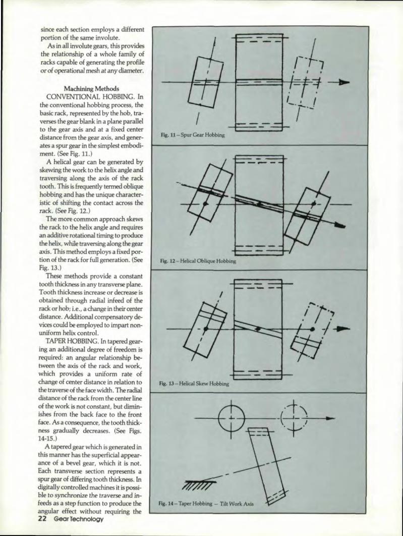
Machining MethodsCONVENTIONAL HOBBING. In
the conventional hobbing process, thebasic rack, represented by the hob, tra-verses the gear blank in a plane parallelto the gear axis and at a fixed centerdistance from the gear axis, and gener-ates a spur gear in the simplest embodi-ment. (See Fi~. 11.)
A helical gear can be generated byskewing 'the ~o.rlto. the helix angle andtraversing along the axis of the racktooth. This is frequently 'termed obliquehobbing and has the unique character-istic of shifting the contact across therack. (See Fig. 12.)
The more common approach skewsthe rack to the helix angle and requiresan additive rotational timing to producethe helix, while traversing along the gearaxis. This method employs at fixed por-tion of the rack for full generation. (Seefig. 13.)
These methods provide a constanttooth thickness in any transverse plane,Tooth thickness increase or decrease isobtained through radial. infeed of therack or hob; i.e., a change in. their centerdistance. Additional compensatory de-vices could be employed to impart non-uniform helix control ..
TAPER HOBBING. In tapered gear-ing an. additional degree of freedom isrequired: an angular relationship be-tween the axis of the rack and work,which provides a uniform rate ofchange of center distance in relation to.the 'traverse of the face width. The radialdistance of the raek from the center lineof the work .is not constant, out dlmin-ishes from the back face to the frontface. As aeonsequence, the tooth thick-ness gradually decreases, (See Figs.14-15.)
A tapered gear which is generated inthis manner has the superficialappear-ance of a bevel gear, which it is not.Each 'transverse section represents aspur gearo] differing tooth thickness. Indigitally controlled machines it is possi-ble to synchronize the traverse and in-feeds as a step function to produce theangular effect without requiring the22 GearTeennolOQV
r-tl--~~-f-~~hF*~ ~
I
I.
Fig. 11- Spur Gear Hobblng
Fig. U - Helical Oblique Hobbing
Fig. 13 - Helical Skew Hobbing
Fig. 14 - Taper Hobbing - Till Work Axis

>>>>> -
Pig. 15 - Taper Hobbing -Till Cutter Axis
Hg. 16-Spur Taper Gear
Fia. 18 - Umil Geometry
Fig. 17 - Helical Taper Gear
added degree of freedom in the macmn ~tool. The helix may be obtained byobli-que orientation or by supplementaltiming.
TAPER SHAPING. By employing acircular gear type cutter in place of therack for generation, the sam require-ments and relations as in habbing ap-ply. However, the resultant taper gearwiU be substantially, but nctexactlv,the same as its hobbed equjvalent.
Taper Gear GeometryBASK (SPUR) GEOMETRY. The
basic geometry of the spur taper gearresults ina complex involut,e helic~i.d.The tilt of the cutting tool path.producesa reduced transverse pressu~ anglesymmetrical on both sides of the toothand a symmetrical base circle for bothflanks. The tool traverse providesreduced tooth thickness in each crosssection.
This uniform reduction is along aconstant helix and resullts in a constantlead of the helicoid surface. It is evi-dent that equal and opposite hand helixangles are produced. (See fig. 16.)
BASIC (HELICAL) GEOMETRY.The basic geometry of the helical tapergear results ina. compound involute hel-icoid. The tilt of the cutting tool path inaddition to the helix generation pro-duces non-symmetricali Hanks 'on theteeth and results in different base circlesfor each side.
The opposing geometric influenoes.,the conventional helix generation withsymmelricaJ parallel flanks and parallelleads, and the action resu,lting from thetaper produces non~symmetry, the re-sult of which is the compound helicoid,
On one flank the action of th taperproduces an increased he1Jxangle andreduced lead, and on the other fI~_k itdecreases the hel:ix..angle and increaseslne lead. (See Fig. 17.)'
UMIT ,GEOMETRY. The limit of ataper gear is identical to ,that of any in-volute of a circle constrained by an op-posing involute ofopposi~e directionaJorientation. The involute becomespointed where the profile paths cross ..(See Fig. IS,)'
for the spur taper gear this crossoveris ,equiangular from. the center line of thetooth, In. the case 'ofa helical taper gear,.there is no tooth symmetry, and thecenter of the tooth apex is the intersec-tion of two opposing involutes struck
November/December 1990 2'.3

from. two different base circles. The in- It would not take a great deal of im-volute angles are obviously different foraginationto' envision automatic meanseach flank. of takeup from thermaJ variations or
The other limit occurs at the base cir- even adjustment based en the loadde of the gear where generatien origi-nates. If the generating too] operates inat zone not defined by the involute, itproduces a degeneration of the desiredprofile. This is the familiar undercut ofinvolute gears with low tooth numberand standard tooth proportions,
TAPER ANGLE. For intersectingdrives, the taper angle mayor may notbe related to the ratio of the mesh ..They operateas lapelled cylindricalgears and are independent of coneangles. (See Fig. 19.)
For example, a 2:1 ratio set couldconsist of both gears with 45" coneangles, or one could be 30Qand its mate,60,0, or any other combination deemedsuitable. There are, of course, somepreferred approaches, but anything ispossible. There is no requirement thatcone angles intersect at a common apex.This allows multiple takeoffs from acommon gear at various angles. (SeeFig. 20.)'
Taper gears operate on pitchcylinders not pitch cones ..It is obviousthat as cone angles. increase, the relativeface width usable must decrease for agiven number of teeth, since the limitconditions of apex and undercut are metata faster rateof change.
HELIX ANGLE. Infinite selection ofhelix. angles is also permissible in crossaxes ,orientation so long as the sum iscorrect. For parallel axis operation thetaper provides a third variable for max-imizing contact ratio and allows reduc-tion in face width for equivalent loadingtoa conventional helical gear.
The combinafion of high cone angleand high helix angle provides a uniquedesign opportunity, since the high helixincreases the virtual number of teethand allows increased cone angle with-out exceeding limits of apex andundercut.
CENTER DISTANCE MATCH. Theta.per gear has the conventional advan-tage of ,employing slight changes in helixangles to provide a given.center distancewhile employing standard tools andtooth proportions.
Taper gears provide even greater ad-vantage by allowing ax,ial change ofposition to accomodate variations incenter' distance or for adiustmeru ofbacklash in over- or undersize centers.24 Gear Technology
envil'onment.The minimum secondary benefit of
the taper gear is that it provides formanufacturing variation without com-promising the mesh or, conversely,allows greater latitude in tolerancingboth gears and housings.
CONTACT. Each spur section of thetaper gear is conjugate to the generatingrack. and contacts the rack continuouslyduring its rotation. Henoe, the tapertooth is conjugate to the generatingrack. Contact between the taper geartooth and the basic rack occurs along astraight line common to the rack andthe taper tooth, and this contact line isinclined. against the pitch plane of therack. (See Figs. 21-22.)
If two taper gears are meshed at a.shaft angle equal to. the sum of thegenerating angles, a hypothetical racksurface .of zero thickness may be as-sumedas existing between the meshinggears. This hypothetieal rack surfacemeshes with both component partswhich are contacted along two strnight,non-parellel lirtes on opposite sides ofthe rack surface. At the point of inter-section of the two contact lines, simul-taneous contact exists between eachtaper gear and the rack. and, therefor~,also' between the two taper gears.
If the rack surfaceis ignored, it maybe concluded that mating gears of thischaracter which mesh at non-parallelaxes are conjugate to each other, butcontact only at a point which travels, asthe gears rotate, on the tooth surfacesand through space. If thecone angle issmall, the tapered gears approach spurgears,a~dthe contact approaches linecontact. (See Fig..23.)
Contact may range from line contactwith a rack or parallel axis mounting to,point contact on cross axes similar to so-called spiral gears ..Separation of pitchplanes is possible, providing all the lee-way for matching centers and ratios in-herent in those gears, with theaddi-tional feature of backlash takeup,
CROWNING. lneommen with ellinvolute heliceids, the line of contact isinclined across the face of the rack. Fullface contact is obtained by parallelmounting in an anti-backlash mode.Angular mesh provides a meshing angleequal to the sum of the taper angles, and
the contact lines are indined to eachother .. These linesare straight lineelements representing contact with therack, but provide theoretical limitedcontact at their intersection ..IneHect thetooth profile is crowned in both the pro--file and lead directions.
Judicious use of mismatch in crown-ing can provide all the desirablecharacteristics of controlled crowningfor dellection, mismatch, or load com-pensation, enabling smooth transitionfrom no-load to load and avoiding 'theharmful effects of heavy end bearing.
Taper Gear featuresCOrvtMONAUTY. All gears gener-
ated hom the same basic rack have acommon normal base pitch and are,therefore, conjugate to each other nomatter what the 'taper inclinalion orhelix angle of an. individual gear.
UNIVERSAUTY. With unlimitedangIe selection for prOViding motioncontrol between any two places in spaceat any ratio, these gears have the mostuniversal application of any motion'transmission device extant. In. parallelapplications optimized involute lengthand helical overlap provide E·oI' max-imized power in a given face width.
lNTERCHANGEABIUTY. Tapergears are interchangeablewithout re-quirement for matching or provision forpairs or sets. Because of variation insen-sitivity, the only moults of mismatch areslight bacldash differences whi.ch can. becompensated for by axial shift ..Off-the-shelf gear replacement is possible evenin the most demanding application.
Taper gears are subject to the same in-spection procedures used for spur andhelical gears. They can be inspected forall elements, such as involute, lead,spacing, runout, and pitch, as weD asfor composite operation with single ordouble flank inspection ..
NOISE REDUCIBIliTY. In parallelgears all the parameters for successfulreduction of dynamic variations areavailable for optimizing. High profilecontact ratio, helical overlap, andvariable addendum with progressionfrom all-recess to all-approach action,pmvide the tools from pursuing mini-mum noise design. Cross-axis .applica-tion tends to be naturally quieter as aconsequence of less dynamic variationdue to the natura] crowning effect.
MESH lNSENSlTIVITY. The three-dimensional curvature of the taper gear

Hg.l'9-Cone/Taper Independence
fig. 2O-Angle Independence
Fig. 21-line of Contact - Spur/Helical
Fig. 22 - Line of Contact - Taper Gear
Fig. 23 - Line of Contact - Non-parallel Axes
November/December 1990 25

Al<vgjute
Fig. 24- Angular Insensitivity - Axvolute Mesh
Fig. 25 - Position Insensitivity
I
•• U u;a''," .020'r .,. n u2i1
.,. 25,·'/
.\t r'\.ec
...... ,
t-,;]-.,. t....'I': 1"'-
~Q
r
Fig. 26 - Backlash Insensitivity
.000 001 002 QCli .CIOIi DQI. OCIIII dOf 001 .DOI 010
I ""~ ~III, It"l r '.i I'''' t '. 1.1Jt.i llUt !:tII1 I ;r'"
Hg.17-Rack
Fig. 28 - Parallel
26 Gear Techno,logy
Fig. 29- Spur
Fig. 3D-Helical
Fig. 31- Multiple

Fig. 32-Skew
Fig. 33- Taper Wonn
Fig. 34-Worm
Fig. JS - Differential Zero Backlash
tooth results in a remarkable ability Itoresolve angular misalignment, axisskew, deflection, twist, and positionalmismatch without affecting conjugateaction. The only requirement for meshis a common base pitch. (See Fig. 24.)
Positional mismatch is limited onlyby the tight mesh condition, which canbe relieved bya simple axial shift ofeither member. (See Fig. 25).
BACKLASH CONTROL. An out-standing feature of taper gears is theirability to be set for minimum. backlashmany mode by axial adjustment of onemember to take up play, without affect-ingcenter distance or mesh integrity.For parellel-axis mode, the taper anglecan be selected to provide any d~ ofsensitivity ..(See Fig. 26.)
Precision differentials have been con-strueted to pr,ovide zero backlash andessentially zero lost motion transfer be-tween input and output shafts. (See Fig.34.)
UNUMJTED ORlENTAHON. Ta~per gears can be employed on intersect-ing or non-intersecting axes, parallel ornon-parallel, and any ,angle of orienta-tion. (See figs ..27-35.)
Conclusi.onGiven 'the remarkable geometric pro-
perties accruing from this simple con-ceptual change in basic gearing fun-damentals/combined with theavailability of axis-synchronizedmachine tools, the taper gear providesa new tool to the general gearingindustry.
Note: Taper gears are generally referred to as"Beveloids" in the literature, however. ,this ar gistered trademark of Invincible Gear.
Re1erences:1. BEAM, A.S."Beveloid Gearing."
Machine Design, Dec. 1954.2. MAY, l.I, Gear Des.ign for Tapered
Inuolute and RaCKand Pinion Steer~ing Gears, Ford Motor Co., 1982.
3. MERRITT, H.E. Gears, 3rd edit.,Isaac Pitman and Sons, Ltd., 1954.
4. VOGEL W.F. - IntJolutometry QndTrigonometry, Michigan Tool Co.,1945 ..
Acknowledgements: Printed with permissiO'l ofthe copyright holder. the American GearMal1ufactuiw5 Association. The opinions,statements Il1'Idconclusion presented intire paperare those of the Au thor aJld In 11.0way rep.resent,the position or opinion .of the AMERlCANGEAR MANUFACTURERS ASSOC1ATION.
Our thanks to MR. WlLUAM L. JANNlNC1( for'l55istll1'l£:e wilh' the technical editing .of this article.
NovemberIDecember 199027

Put:s ilt all toget:herwi'tlh excitingl" newproducts to keepyOlu competitive,!
Gearrnakers worldwide face customer demands for highest quality and on-time delivery at fiercely competitive prices. Meeting these demands requiresgreater flexibility, productivity and the ability to integrate new technology.Recognizing your ultimate goals - customer satisfaction and pmfitabHity -IKHngelnberg'global! technology is ready with the most advanced CNC SpilrallBevell Gear Generators and Grinders, and the most complete line of CNCGear Checkers avahable ... anywhere.
We've ,put it all together:Spiral Bevel Gear Appliicat,ions• KNC 40/60 fully GNG controlled Generators• AMK Large Gear Generators• W800CNC (Wiener System) Grinder• CNC Inspection Equipment• Quench PressesWorm and Rotor 'Grinding AppHcaUons• HNC Series of GNG controlled Grinders• GNG lnspection Systems
Parall'el A.xisGear Applications• GNG controlled gear Inspection Systems• SNC Series of CNG Hob Sharpeners• Gear Gutting Tool Inspection Systems• Hurth Product Line: GNG Shavers, Hard
&. Fine Finishers, Shavinq Gutter G,rindersand Deburring/Chamferilngl Equipment.

The KNC-4D/60 Gear GeneratorsThese new, fully CNIC, B axis gear generators produceSpilral Bevell Gears up to 24" 0.0. Pertect for smallbatch or lintermediate I'evel production runs, the KINCSeries 'generates Spiral Beve,I'Gear:s of any geometryby continuous or single ilndexing operaucn. Its programstorage capaci~y for 250 different workpieces andunlimited storage ,capacity with a ONC intertace, makesit the most flexible, gear g:ener,ator you esn buy.
The WaDDCNC Gea.r Grinder (Wiener System)With leading edge technology, the WBOOCINC becomesthe uni,versall Spiral !Beve:1a-ear 'grinder #or any 'geargeometry. Perlect for ,ground: g:ear quality applicationsup to 315" 0.0 .•the 'grinder offers gr,eat versatility,short set-ups and superior accuracy.
The PNC Seilies Gear Check.elscempaet new CNC ,ccOntroliedgear checkers providefully automatic measuring ,of gears up to BO" O.ID... Eastoperation, high accuracy, e'xceillent documentancn anda wide' vari:ety 'of software modules, term the perlect.,gear checking package.
For the latest information on Klingelnberg systems thatsatisfy customer demands, fm tncreased productivityand profitability. contact our representative. Or. wrHe toKlingelnbergl Gear Technology tne.,15200 IFoltz Industrial Parkway. StrongsvBle, OH 44136.Phone: 2116/572-2100: FAX: .2116/572-09B5.
@ KLI~GELN~ERG- rouPuts It ,all tog,ethe.r~
CU~CLE A-116 ON IREADER'IREPlY CARD

in Order to Avoid Undercutting
Dr. Vadim KinPurdue University
Hammond, IN
Abstract:The dimensions of the worm and worm gear tooth surfaces
and some of the worm gear drive parameters must be limitedinorder to avoid gear undel'cutting and the appearance of theenvelope of lines of contact on the worm surface, The authorproposes a method for the solution of this problem. The rela-tionsbetween the developed concept and Wildhabers con-cept of the limit contact normal are investigated, The resultsof computations are illustrated with computer graphics ..
Basic Kinematic EquationsInvestigat.ion of Undercutting of Spatial Gears. The in-vestigation is based on the .following equations and theoremsthat have been. proposed by Litvin.(1.2)
v (I) + vfU) = n_r __ ~
d (. , . (ull _ d [f( .n .i.)] - f du + f dO + f d¢ - 0- 1): Jl - - U,U, 'i' - u- F ..~- - .~ ili ~ ~ ~
where: 2:r(l) is the velocity of motion of the contact pointover the worm surface, ,Y(U) is the sliding velocity, n is theworm surface unit normal, u and (JaJle the worm-surfacecurvilinear coordinates, and ¢ is the generalized para-meter of motion. Equations 1 and .2 yield the followingequations30 'Gear Teehnoloa,r
(1)
(2)
OXl OXI V (12)Xl
au ao'
arl oy! V (12)Yl
au ae
af of ilf-wau ao o'¢
=
aXl aXl v(2)__ "1
au ae
aZI ihl V!~2)
au ao
of Dfaf--wau aoa¢
,(jYl (}Y'l v(U)__ Yl
au 00'
aZI aZl vg2)
au 8()
a.f af of--wau ao a¢
=0' (3)
Here:..[1 (u,O) = Xl (u, ()) il+ Yl (u, fJ) jl + ZI (u,O) lsI (4)
are the equations of the too] surface El and (u.lI) are the

Contact Lines
Fig. I
Envelope of Contact Lines on the Worm Surface. Theenvelope of lines of contacton surface E], if it exists, isdetermined by the following equations:
(5).£1= f1 (u (J) n : V(12) = f(u 8 .J". ) = 0
- I '.-..;: _ ' .'I!'
eurvilineae surface I:}coordinates. Surface E1 is a regularsurface, and
n . ;y(12) = £(u,O,I/» = 0
is the equation of meshing with </)as the generalized
parameter of motion. (One may chose that</) == </)1and d</)dt
== w(l) where 4>1 is the angle of rotation of the tool.) Thesliding velocity ill) is represented by
where se(12) - !:d(1) - !:d(2); Lis the position vector of theinstantaneous contact point M that is drawn from the lineof action of the' sliding vector !t!(1) to M; ,B is the positionvector that is drawn from the origin of L to any point of thesliding vector !t!. (2)
Equations 3 yield the relation
F(u,(J, </) = 0
Equations S, 6, 4, and 7 determine a line L on surface E1that generates singular points on surfaceE2• We call L thelimiting line because if El is limited with L, singular pointsonE2 do not appear.
,afq (u, (J, </) = .- (u, 8, </) = 0
fJ4>(8)
Fig. 1 shows an envelope of contact lines on the surfaceof an. involute worm. The existence of an envelope on I;l isnot desirable because a part of 'the worm surface withoutcontact lines is without meshing, and the conditions of heattransfer and lubrication in the area dose to the envelope atI'e
not favorable. For these reasons, the existence of theenvelope of contact lines must beavolded. This can be doneby choosing the appropriate design parameters for the geardrive.
Instead of the envelope E on surface El, an enveJopeofcontact lines on the plane P of surface curvilinear coor-dinates (u, tJ) might be considered (Fig..2). Both envelopes,
(7)AUTHOR:
DR. VADIM iaN completed his graduate studies in mechll11icalengineering at the Urliuersity of lI/inois at Chicago in the summerof this year. He is presently a lecturer a! the Purdue University -Hammond, IN, campus.
November/December 1,990 31

A PATH TO WMW:NILESGENERATINGGEAR
WMW:NILESZSTZ O8IEG-ONC
WMW:NILES G.ear Generating Grinders arein demand ,everywhere! TM world's mosttechnologically advanced nations look toWMW:NIUES for thls equipment-and for goodreason.
-Tile NILES GeaJ"Generating Process is thefastest. and most cost effective method forgrinding smalland medium production funs.
• NILES meets your requlrements with a fullline of automatic grinders with gear diametercapacities from 1/2:' to 158" .
• AL.L NIWES gear grinders l1aveaccuracies toAGMA 12/14. -
Customiz.ed mac~hinescan be ordered with evenhigher guaranteed accuracies.
~u won't find a better Gear Generating Grinderanywhere. Thars why companies like yours have.bought over 4600 of them, making WMW:NlLESGrinders most p19ferredthroughOut the world.
PA:RTIAL. USAGE. SURVEY (as of 1988)COUNTRY *' OF MACHINES
Federa'i Republic of Germany 350Japan .287Italy 175FranceGreat IBritain 1'01North Americ-a 411Switze~I'and 15
Comp'ete Infonnatl'on lis, available on IreqUest
'WMW Mach'inery; Inc.570 Bradley Hm Road
Blauvell, New York 10913Phgne (914) 358·3330
Fax (914) 358·2378Telex 4756017
QIRCLtEA-lI7 ON IREAOER' IRE:PLY CARO

if they exist, appear simultaneously en 1::1 and on P. It is !h = I =N-11-1'~1 = iJa"'",uf,I X a,a:]easy to verify that at the point of the envelope, the direction _ I)'
of the velocity of contact point in its relative motion oversurface 1::1, ~r(]) cannot differ from the tangent to the that yieldenvelope. This means that ~r(1) is equal to. zero in any direc-tion that differs from the common tangent to. the contact line III = sinAbsinO Jl - sinAbcosO jl +COSAb lsI (10)and the envelope"
•
BDnlope
fig. 2
Applica'lionsto tlle Involute Worm G'ea:rDriveThe proposed approach is applied to the case of an involute
worm gear drive. The goal is to. determine the design,parameters with wtdch the appearance of the envelope ofcontact lines on the worm surfaceE]. and the appearance ofsingular points on 1::2 can be avoided. Worm tooth surfaceEl is a screw involute surface represented in coordinatesystem 51 rigidly connected to the worm by the following,equationsPJ
p8 - us~
f"COsO + uco~in8
rt,SinO - ucos)q,cos8
where u and ()ar-ethe surface curvilinear coordinates, tb and}.q, are the base cylinder radius and, the lead angle on thiscylinder. The screw parameter (p>O for a right-hand thread)is p = rbtaMb. Equation 9 works for both side surfaces if u isconsideredas an algebraic value. The surface El unit normalis represented by the equations -
8
J'i
Fig.J
Equation of Meshing for Worm Gear Surfaces. A hob thatis identical to the worm generates the worm gear tooth sur-face. The meshing by cutting of the hob with the to-begenerated worm gear simulates the meshing w:ith the wormgear in the drive. Coordinate systems 51< 52' and S, arerigidly connected to the worm, the worm gear, and theframe, respectively. (Fig. 3) The equation of meshing isrepresented as fol1ows:
(9) _ (p 1 - m21cosA _ E) COSAbm.21smy sin (8+cpl)
where cp is the angle of rotation of the worm, l' is the twist
w(ZIangle of the worm gear axes (Fig..3), and mt2 = - is the
wmgear ratio. The worm gear tooth surface is represented by
(11)
[r2] = [M211 [rl], f(u,O,¢1)=0 (12)November/December 1990 .33

where the 4x4 matrix [Mzll describes the coordinatetransformation in transition from 51 to S2'Envelope of Contact Lines on E1. The envelope of contactlines onEl is determined by the equations
af.1'1 (u, 0), f(u,O,¢l) = 0, - = °
a¢l
The envelope of contact lines on the plane of parameters(u,O) is represented by the equations
aff(u,8'¢1) = 0, --- = °
a¢l
that yield
«() +-A.) _ rb + E cot')' taMbcos· '1'1 - -------'----
1- m2lcos/,p . - - E
m21sin/,
It is easy to verify that the envelope exists if I cos «() + cP1) I~ 1.The appearance of an envelope of contact lines may beavoided by appropriately chosen design parameters. For aone-thread worm the parameter is the twist angle 'Y, and foran orthogonal ('Y = 90°) worm gear drive it is the number ofthreads, i.e., the lead angle Ab'Fig. 4. shows that the contactlines on El do not have an envelope in the working space inthe case of a two-thread worm. with the lead angleAb=21.68°, "(=90°. We emphasize that the pattern of con-tact lines favors the conditions of lubrication and efficiencyof the worm gear drive.Singular Points on Ez. The investigation of the singularityof E2 is based on application of Equations 3. Fig ..5 showsthe limiting line L on the plane of parameters (u,8). Theworking space of the worm must be limited with L(u,8) toavoid the appearance of singular points on E2•
In the case of the worm gear drive, the envelope of con-tact lines and the limiting line usually do not appearsimultaneously. However, in some particular cases thesetwo lines may have a common point as shown in Fig, 6, Thecomputationsand drawings correspond to the case of athree-threaded worm gear drive with the followingparameters:
m21 = ~, "{= ~,E = 150, rb = 40.29, hb = 16.59°25 2
The common point of both lines appears in the non-workingspace of the discussed example.
Relations Between Concepts of Line Contact Envelope,Singularity of I:11 and
Wildhaber's Concept of Limit Pressure AngleWildhaber's concept of the limit pressure angle has been
developed on the basis of scientific conditions of forcetransmission by gear tooth surfaces. (4.5,6) However,Wildhaber's equations may be and should be interpretedgeometrically ,and this can be done on the basis of the con-cept of the envelope of contact lines and the concept of34 Gear Technology
(13)
(14) Fig. 4
Fig. 5
! U
L
Envelope eFig. 6

singularity of generated surface E2• Consider the equationof meshing that is represented by
..B' yll2l= B' (J,t}(12) X r. - .8 X ~(21) - 0 (15)
The equation of meshcr.g is observed in the neighborhoodof the contact point, and, therefore, we have
Let us differentiate Equat ion IS,assuming first that 1:r (2) =0and singular points onE], appear, and then 1:.(1)=0, and an.envelope of contact lines exists. We assume by differentia-tion that vectors .8, ~(l), JIP1, and !eml = 5!}(Il- 5!}11,1areconstant. Generally, the differentiation of Equation 15 yieldsthe following equation:
( n (i) + n (i»), •. v(12) + EO). ( ,.,(12' X ( V (i) + v (;»)1 = 0_r _ tr _ ;c _f _Ir
Here:
n (j) = (.,(0 X EO) v(2) = v C1I- V. (21 and_tr "iC' - , _ -..b" .......tr'
is the common contact normal. Considering the particularcases where :t.P·)=O and singular points on 1:2 appear;J!.r(II=0,. and an envelope of contact lines exists, we receivefrom Equation 17 that
In addition,we have to, c~nsider that the contact pointsatisfies the equation 'of meshing (15). Equations 18 and 15,H ",,·_ced·1 r vid .";- eonditi ." h 'r' .'if.-- singul arities5au:.u _,p_ 0 __e lilt: _ .ons w. en ""'2 ~'!4:> _ _ .. __
or the envelope of contact lines on 1:1 exists, or bothsingularities on E2 and the envelope on E] existsimultaneously ..The disadvantage of application of Equation18 is that it is impossible to recognizewtuch of the three abovementioned eases tis observed. The direction of the contact nor-mal .n depends on two design parameters - 'the helix angleon the worm. and the pressure angle. The application of Equa-tions 18 and 15 may provide information about the limitpressure angle if the helix angle is considered as given.
ConclusionMethods for detennination of an.envelope of contact lines
on the generating surtfaceand si.nguI...ar points on Ithegeneratedsurface have been developed and appli.ed to the case ofin-volute worm ..gear drives. A bridge between the developedtheory and Wil:dhaber's concept of the limit ,contact nonnalhas been. established.
Admowled,geme..nt: Reprinted' wiln permissfol1of the Americlin GearMlmuf4idureT5 Association. The opinions. statements. and condusionspres.eflted in this pllper are those of the Aulhor and in no way representrite position or opinion of the AMERICAN GEAR MAMUFA CTURERSA.S50ClA.TION.
(16)
Referenoes:1. LITVIN, F.L. Theory of Gearing. 2nd Edition, Nauka,
Moscow. 1968. (in Russian). The English version is publish-ed by NASA, References Publica.tio.1I 1212, AVSCOMTechnical Reporl88-C-035.
2. LITVIN. r.t.. RAHMAN.. P .. GOLDRICK R.N."Mathematical Models for ItheSynthesis and Optimization ofSpiral Bevel Gear Tooth Surfaces", NASA Contractor Report3553,1982 ..
3,. LITVIN, F.L "An Analysis of Undercut Conditions and of A~pearance of Contact Lines. Envelope Conditions o'f Cears",ASME Transactions, Journal of Mechanical Design. July,1978, pp, 423-432.
4. WILDHABER, ERNEST, NBasic rtela.tio.llship of HypoidGears", America'n Macllinist. Vol. 90. No.4. February 14,1946.
5. VVlLDHABER, ERNEST. "Bask Relationship of Hypoid Gears-jr. American Machinist. Vol. 90, NO'.5, F-ebruary.28, 1946.
6. VVlLDHA.BER, ERNEST. "Basic Relationship of Hypoid Gears- IV", American Machinist, VoL 90, No.6, March14,1946.
T,HE'GEAR D'EB,UR'R',IN"G
S,Y,ST,EM----~--
The James Engineering Systems approach.through modular components, can build uponthe standard unit Ipicturedl' to create a customt3ilored paCkageto meet each customer's needswith speed. flexibility and predston never beforeavailable. Optional packages inolude:
• CNC Controls '. Up to• Auto Load/Unload 4 Operations• Dust Collector per Cycle
JAMES ENGIIN,EERING11707 McBean !Dllve. EI Monte. Califomia
8~8 44.2-,2898 .' FAX 818 442.03:74
CIRCLE A-UJ ON IREADER' IREPlY CARDNovemberIOecemberl990 35,

cs
IntroductionSome years back, most spiral bevel
gear sets were produced as cut, casehardened, and lapped. The case harden-ing process most frequently used wasand is case carburizing, Many largegears were flame hardened, nitrided, orthrough hardened (hardness around 300BHN) using medium carbon alloysteels, such as 4140, to avoid higherdistortions related to the carhurizingand hardening process.
The use of a quench press can con-trol, but not eliminate distortions .. Alapping operation cannot remove run-out, pitch error, profile error, and othererrors caused by heat treatment dis-tortions. It can only improve activetooth profile finish and tooth contactlocation, provided that gears did nothave excessive errors during soft cuttingor high distortions in heat treatment.As a matter of fact, overlapping some-times does more harm than good on abevel set,
Bevel tooth grinding was very limiteddue to cost and size.
Advancement in bevel generators,carbide technology, and many otherfactors allowed introduction of hard36 Gear Tecnnology
Yogi Sharma,Philadelphia Gear Corporation
King of Prussia, PA
cutting inbevel gears. Initially, the pro-cess was limited to special requirementsbecause oflowcarbide tool life, the needfor frequent sharpening, and limited ex-perience. But the picture changed dra-matically after some time. The ex-perience gained and the development ofthe CBN (Cubic Boron Nitride) toolmade bevel gear hard cutting very efiec-tive from cost and quality viewpoints.
As with any PIlOCe5S, hard cutting hasits limitations and problems. A properlycontrolled process, starting from thedesign concept, good bevel generators,hard cutting tools, including sharpeningfixtures, special machines, and trainedwork force, are a must for successfulbevel hard cutting.
This article describes the process andsteps required for spiral bevel hard cut-ting on small batches or in a jobbingatmosphere.
Process DescriptionBevel hard cutting can be defined as
an operation in which gear teeth flanksare finished by removing the stockallowance left during the soft or roughteeth cutting. The process is similar to
gear grinding, with almost all the opera-tions remaining the same, with the ex-ception of tooth grinding, which is re-placed by hard cutting.
A simplified manufacturing processsheet for a hard cut bevel gear will con-tain the following:• Complete machining of gear blanks
for teeth cutting - including variousoperations, such as turning, milling,drilling and tapping, etc.
• Bevel teeth cutting - consisting ofteeth cutting, testing, and any toothcontact development with master ormate, teeth deburring, etc.
• Heat treatment- mostly case car-burizing and hardening (nitriding,flame hardening, and inductionhardening are rarely used for hard cutbevel gears).
• Finish machining - all machiningoperations required before teeth hardcutting, such as turning O.D.ll.o..grinding, special machining, etc.
• Hard cutting - bevel gear arrives athard cutting with most or all opera-tions done. It is important that themating part or master is available fortesting purposes. Normally, the gear(member with higher number of

teeth) is finished first and pinion teethare modified to get correct tooth con-tact along profile and length of tooth.The modification for length of contactis nonnally made by change of radiusof curvature of the cutting blades. Thelocation of tooth contact along thelength is usually controlled bymachine settings. The profile correc-tion or modification can be made bydifferent means depending on thetype ·ofmachine or system used to cutbevel gears, size of gears, and pitch.On fine pitch gears, high pitch linehearing can be obtained by using cut-ter blades wi th modified profiles ..Oncoarse pitch gears, profile modifiea-tion 'can be made using taper shims.Once the tooth contact requirementsare met, the gear teeth are finallychecked for spacing and mounted ona gear checker.
• Final inspection - includes dimen-sional checks, magnaflux, and a-"yother specialrequirements.
Ad.v.antages ,ofHard. Cutting• Higher power transmission by
spiral bevel gears, as both members arecase carburized and hardened andfinished by hard cutting.
• Higher and predictable qualitylevels in gear teeth.
• A surface finish of 16 Rl\1S orbetter.
'. Lower noise level lower internaldynamic forces due to higher geometricaccuracy, and better load distribution.A hard cut bevel set signifkantlyreduces the gear box vibration problemcaused by higher intemal dynamicforces due to poor quality gear teeth,which can cause premature gear boxfailure,
On the other hand the gear grindingoperation is always very sensitive tomany factors, such as rate of material.removal, grinding wheel, coolant, 'etc.Any compromise or loose control cancause surface t.emperingor cracks orboth ..Surface temperingor cracks are
practically unknown problems in hardcutting .
•' Hard cutting is performed on thesame 'type of machines as soft-cutting,making the process much moreeconomical ..Of course, special toolingis required.
• The same person or group ofper-sons are involved in soft and hard cut-t:ing. It has been found that control inroughing operation (soft cutting inbevelgears) is quite important fora successfulfinishing operation. Proper stock allow-ance, tooth depth, tooth contactretc.are necessary for bevel hard cutting.Too much stock. allowance can causeloss of case depth and longer cuttingtimes, while too Iittle stock allowancealso can cause a variety of problems.Hard cutting time cycles can be reducedby making some adiustrnents at softcutting for heat treatment distortions,and it can be done very simply, as bothoperations are performed by the sameperson or group of persons.
• Consistency in bevel hard cuttingcan eliminate the need for matchedbevel sets by careful. planning. Some ofthe requirements for elimination ofmatched sets are as follows:- Manufacturing and storing of casehardened and hard cut master gearandpinion for checking the gears and pi-nions in all future setups.- Optimization of design and cuttingdata so that it does not have to changefor the period unmatched sets arerequired.- Tighter control of critical dimen-sions on gear Ipinion blanks. Hard cutunmatched sets are not only useful. inassemblies, but they can eliminatemany production problems, as eachmember can be processed independentof others. The unmatched set approachmust be used very selectively, as it needscareful planning, customized fixtures,optimized design, cutting summaries,and long term commitment. The un-matched set approach combined withstandardized bevel sets can cut down
delivery times and cost very effectivelyin spiral bevel gear boxes,
PreparationFollowing are some items which
should be considered in detail for suc-cessful and economical bevel hardcutting.
Practical Tooth Design. A balancedtooth geometry is a must fora goodhard cut set. All new tooth geometrymust be reviewed carefully from amanufacturing point of view. In a job-bing or low batch environment, the newtooth geometry should try to use ex-isting tools, as new tool requirementscan cause cost and delivery problems.Even in high batch production wheretools can be designed around gears,poor tooth geometry can cause multipleproblems, such as low too] life, smallerfillet radius, etc.
Gear Blank Design. Fig. 1 to Fig. 4show a bored pinion, a stem spiral bevelpinion, iii solid gear, and a ring typegear. As shown in F.ig. 2, the bevel pin-ion can be indicated in both planes bymeans of an extra extension in front ofthe teeth. Both gears show prool bandsfor indicating the gear blank at hard cut-ting. Special attention must be paid inblank design so that revalidated proofsurfaces at final machining can be usedfor indication purposes at hard cutting.In high batch production, blanks, tru-ing, and use of proof surfaces are not re-quiredbecause of special customizedfixtures. Still, it is good practice to createproof bands at final machi,ning for in-spection or assembly purposes. In the
AUfHOR:
YOCI SHARMA is employed in gearmanufacturing .and design at PhiladelphiaGetlr Corp. He holds an M.S. degr:ee ,inmechanical engineering from ViIlanovaUniversity and one in jndustrial.engineeringfrom Perm State. Mr. 5hatmais a .licensedmechanical engineer .in tne state .of Penn-syivaniJ:! and' a-senior member of SME.
November/December 1990 37

-
Fig. 2
38 'GeoT Technology

, r CC 1. H
M~ i~~ E;:z =; :a
R~ i:~ ~
311 511
UA'I( 015 ... 1.DUA..:f 1)0 _00:.1:1 I[ lDIJi'O t&l""J[Ji! ~IB!ING"'liD IiJ"DI( HAQ!!tJiHII«.
Fig. J------ - - --- -
- ---- -
:F!g.4
.. '
November/December 1,990 39'

case of a bored pinion/gear, thesubassembly with shaft should be donewherever possible to avoid concentric-ity and squareness problems (Fig. 5).Fig. 6 shows the subassembly of a ringgear and spider. In pinions, the one-piece design does offer some manufac-turing advantages over the two-piecedesign. Also, small to medium size gearsshould be investigated for one-piecedesign, as there are some manufacturingadvantages in the one-piececonfiguration.
Previously, gears were mostly de-signed as bored rings so that they couldbe die quenched, but hard cutting haschanged the picture somewhat. Distor-tions in free quenching of small tomedium size solid gears can. be kept lowwith proper control. Hard cutting willremove the distortion from teeth. Cau-tion must be used for any switch ove.rfrom two-piece design to one-piece.There are many factors which affectdistortions in heat treatment, such asmaterial blank configuration, rixturingin heat treatment, etc. Vl/herever possi-ble, some experimental pieces should bemanufactured to evaluate the situationbefore making the final decision, as ex-cessive distortion is highly undesirableand can cause various problems at hardcutting.40 Gear lechnoloov
Soft and Hard Cutting Summaries. Atooth cutting summary for a beveJgenerator provides machine set up data,cutter data, tooth measurements, andother tooth geometry informationrelated to a specific spiral bevel set.Bevel hard cutting blades are very sen-sitive to proper feed and speed. Selec-tion of correct amount of crowningstock allowance affects the overallqual.ity and cutting times. Normally, inhigh batch production, a sample set ordummy set is always useful to fine tunethe summary ..In a jobbing or low batchatmosphere, a dummy set or experi-mental set mayor may not be possiblefor various reasons; therefore, a jobbingatmosphere requires initial selection ofall variables affecting tooth contact.The length and location of tooth contactshould be based on factors, such asassembly conditions (overhung orstraddle mounted members), tooth stif-feners, and loading, application,andpast experience. Wherever possible, finetuning of tooth contact can be achievedthrough load testing of bevel gears.
Heat Treatment Process ControL Ex-cessive heattreatment distortions arehighly undesirable for hard cutting ofbevel gears for a variety of reasons, suchas loss of case thickness, longer cuttingtimes, tooth thickness problems, and
mounting distance problems. Ringgears must be die quenched' utilizingproper quenching dies. Fig. 7 shows a.quench press. A pre-quench and temperoperation of rough-turned blanks forlarge gears and pinions can assist instabilizing the pieces during heat treat-ment. In the jobbing atmosphere, gearsand pinions should be checked. fordistortion belore releasing for finalmachining.
Finish Machining Operation. Thefinish machining of gears and pinionsfor hard cut bevel. gears is very im.por-tant. The runout and squal'eness and aliother geometric tolerances of beari:ngdiameters, proof diameters, etc. must bekept to less than 40 % of the valuesallowed on the gear teeth. Any loosecontrol in finish machining operationscan add to distortion, leading 'to longercutting cycles and various problems. Itis vita] that proof surfaces in both p1anesare indicated within specified valuesbefore proceedingwi.th final machining.The big difference in the fina1 machin-ing of a lapped and a hard cut gear isthat, in the event of a lapped set, theback face or mounting face is usuallyleft as it is, while in hard cutting, it isground or turned square to bore. In ad-dition, it is critical 'that som extramaterial is left in the back of a hard cut

.fbI' Y01ur tougllestg ~.._~rcutt.--ng Jobs,
,tile lIardest ,ste,el JS,the easl ~'.-t clJQ -'ce
For hobs, shaper cutters and other gear cuttingtools. that are more than a cut above the rest, specifyGrucible CPM REX~ 76. With 33% total alloy con-tent and an attainable hardness ot HiRC68-70, thishliglh speed steel provides. the highest availableco-mbination of red hardiness, wear resistance andtoughness, either coated or uncoated,
A 9ig- Three US. auto maker mcenUy realized a300% -improvement in gear cutting tooll life byswitchingl from 1M3 HSS to CPM REX 716. Withgr,ealer too~lllifeand excellent grindability, CPM REX76 means less downtime because resharpening iseasier and less frequent -
Ill/iii?!_____ 11
• I•• CPMREX'76CPM REX 76 is just one of 10 high speer! steels
produced by the Crucible Particle Metallurgy pro-cess. With the industry's widest material selection,Crucible can meet your specific needs at any pro-ductivity level. You can selectively upgrad:e to thebest CPM material for the right eppllcaton.
On your next order, specify a high speed steelthat's hard to beat ... CPM REX. 76 or another rnem-ber of the CPM REX family. To learn mare, contactyour nearest Grucible service center or call to'll free:
11..800~PAR;"XC;EL(1~800-7.27-9235)
A Division of Crucible Matenals Corporation
CiReLli A-19 ON REAIDERIREPlY CARD

'[xPAIIDIr«; DIEZ tLAHP ING :DI[
L_ CONE
fig. 7
__ -- StTTCUT
IlARDCUT BASICI'IiESSUR£ ,ANGLE
TOOTH TIP
,..__ ~C!i_I DIAMETERI,
IJI
JI,
IJ,
R[]lJT rlLLH
Bg.B
rl NI SHED PROf ILEBY HAROCUTT I NGBLAOC
DEEPER RDOT PRODUCE D .BYHIOlli.t BL~DE
Fig. 9
42 Gearlechnology
,",
gear at blank turning, which will thenbe removed at final machining .. Thiswill reduce the variations in mountingdistances .. In multiple pieces, consis-tency of the crown to back dimension isimportant for hard cutting cycles,Variation will cause adjustments forevery piece on 'the machine, resulting inlonger cutting cycles. Proper proofbands and surfaces must be created atfinal machining, with concern given totheir location as well, so that they can beeasitly used for indication purposes athard cutting ..
Soft Cutting Blades. Fig. 8 depicts ablade with protuberance.Where everpossible, protuberance blades should beused ..They will cut down hard cuttingtime, extend too] life, and reduce thepossibility of steps in fillet. The use ofcustomized protuberance blades is noproblem in high batch production, butin jobbing or low batch production thepicture is quite opposite. Amount andheight of protuberance selection be-comes difficult as blades are stretched tocover maximum range. Blades can stillbe obtained with protuberance selectedvery carefully, which 'Will help hard cut-ting. Setting middle blades slightlydeeper than side blades also helps inhard cutting and is a common practicein bevel cutting. Fig. 9 shows a filletcreated witha deeper middle blade. Fig.10 shows a blade for soft cutting.
Hard Cutting Blades. Bevel hard cut-ting began with the use of carbideinserts. Carbide inserts are damped tosteel bodies for coarse pitches andbrazed for medium to fine pitch gears.In the beginning, low tool life with car-bide inserts, frequent tool sharpening,insufficient experience, high cost. andmany other Factorskept hard cutting'suse quite low. As hard cut bevel gearsreached into the field, their performancein all aspects was the single most reasonto increase the use ofbevell hard cutting.
In the meantime, CBN inserts wereintroduced for hard cutting, The BZN(BZN is a trade mark of General ElectricCompany) compact blank isa combin-ation of a layer of Borozon CBN (Cubic

'Gear Tooll S;peela:lIsls3601 WEST T'OUHY AVENUE
UNC'OLNWOOD" 11'lILlNOIS 606451'08-6,75-2100
1-·800k628-2220 In IlL '·8'00'-628·2221
GEAR TRAINING PROGRAM1. BASIC FUNDAMENTALS
1. a..r HImIryA. Cyefotdal TeethB. Involute TeethC. Gear Cutting MachinesD. Gear Cutting Tools
2. a..rTypeeA. Par811e1AxisB. Intersecting AxisC. Skew Axis
3. OHr Aattoa4. Involut. Gear o.om.try
A. NomenclaturaB. Involutomelry - Contract Ratio, etc,C. Helical Gearw - Lead - Helical Overlap
5. Gear Tooth BystemeA. Full DepthB. Full AlletC. Stub Depth
I. a.n.r.I Formu_7. M8them8tIca - (I.T.W. Trig Book)
2. HI SPEED STEELSA. Common TypesB. Special TypesC. Heat Treatment - M8IaIlurgyD. ControlsE. Sur1lK:e TreatmentsF.Special C_
3. CUTTING THE GEAR1. FonnIng
A. MillingB. BroachingC. Shear Cutting
2. o....,.ungA.She
~lCircu'!'~ypec) Machine Types and Manufacturers
d) Schematic - Principlesa) Speeds - FeedsII Machine Cutting Conditions
B. Hobbinga! The Mobbing Machinab Types and Manufacturersc Schematic - Differential and
Non-Differentialdl Sl*KIs - Feedsa Climb CuI - Conventional CUiII Shifting - Types
3. The Hob ... Cutting ToolA. How It CutsB. Tolerances and ClassesC. Multiple ThreadsD. Hob Sharpening and ControlE. The Effect of Hob and Mounting Errors
on lhe Gear4. The Shaper CUtt..... a Cutting Tool
A. Know Your Shape! CuttersB. Design LlmltallonsC. SharpeningD. The Effect of Cutter Mounting and
Errors on the GearE. Manufacturing Methods
5. Tool Tolet'ance Va. GHr Toter.nc:eA. Machining TolerancesB. Gear Blank Accuracy and Design
Umitations
... FINISHING THE GEAR1, Gear F1nl8tMng - BatON Hardening
A. ShaVInga) The Shaving Cutterb) Types of Shaving - Conventional.
Underpass. Diagonalc! Crown ShaVingd Shaving Cutler Modificationse Co-ordinatlng Tool Design-
The Shaver and Pre-Shave ToolII Re-Sharpeningg) Machines
B. Rolling2. a..r F1rHehlngaft ... HMt: TfNl
A. HoningB. LappingC. Grinding
a) Methods - Formed Wheel·Generating - Threaded Wheel
b) Machine Typas
5. GEAR INSPECTION1. Functional
A. Gear RollersB. Gear Charters
a) Reading the Chartb) Tooth-to-Tooth Composite Errorc) Total Composite Error
C. Master Gears~!=~~i"c Special Types2.~1
A. Size - Tooth ThlcknenB. RunoulC. SpacIngD. LeadE. Involute
3. Automatic: and SamI-AutCMMtk:A. How They WorkB. What Can Be CheckedC. How Fast
4. ChIIr1I~ - An8IytIcIII and FunctionalA. Reading the ChartaB. Which Errors Affect Other ElementsC. How to COI'rectthe Error the Chart Shows
6. INDIVIDUAL INSTRUCTIONAND SPECIFIC PROBLEMSOR PLANT TOURThis Program is IleKlble and chenged 10 meet !heneeds of each group.
The 4-day program consIIts of a coordinated aeries of lectures given by the Engineering,Production and lnapection ata1'l8 of Illinois Tool Works Inc. They represent ovar sixty years ofexperience In gear and tOOlspecialization.
The .... ion. are conducted with a technique and approach that leads to Interningdiscussion and participation. Staning with the basic fundamentale, the program I. directedinto those areas of g.... test interest and value to the people attending the particular session.The groups are kept .maIllO that this object is readily accomplished.
All mentioned, the planned program IU18 tour days. One-half of the fourth day I. for In-dividual dlscunion of apeclflc problems In a detailed manner with members of the illinoisTOOlWorks' ataff.
More than 4,000 Individual. from hundreds of companies repreeenting manufacturing,engineering, Inspection and management, have come to Chicago for these programs. Theyhaw been conducted on a monthly basis .Inea 1958. CI.... have also been conducted InEurope. We are c.rtaln that this well rounded program has helped all of them to a better Joband a110 given them a better underltandlng of engineering, manufacturing and Inspection.
All thole attending are aaaIgned to the same hotel. This promote. friendly contact anddiacuaalon of mutual problems and Interesta. Tuition for the course Includes transportationfrom the hot.' to ITW and back, one group dlnn.r, ali continental breakfasts and all lunche •.
We hope we may Include your company in one of our Training Program •.CIRCLE A-20 ON READER REPlY CARD
ITW ILLINOIS TOOLSA Division of IIIInoI8 Toot8 Wofka Inc.
1991 GEAR TRAINING PROGRAMFour Day Seminara
JanuaryFebrualyMarch .Aprj ""
''''7"."11·"15-1e
MayJuneJulyAugua1
13-1e10-1315-1812·15
,e-li'417"·:4
2·5
TUITION FEE: II1II8.00
NOTEI Additional siudenla, aame CCIInPMy, __ ct.. teeo.OO
Includes ,he ,r8l18pO!1abon from !he hotei to ITW and bKk. one group dIM«.hoepI!aI1\y meeting. conllnantai br~. and aIIl~
Ths 5ocI8Iy 01 Manufaclurlflg Englneera ISM E.) has IIPP"\MId m,. School lorPr01888iona1 Cred<18 10Ward !he S.M E. Recer\IIIca1oo Program Creda are ......m.d
on !he baN 01 ont creel' per c:ontenl hOurFor addII#oMI ~ aonIICt;
ROBERT H. MOOiAOWManager. TI'1Ii'*'II708-675-2100
l.aoo.e21-2Z!OIn IL CIlI: l.aoo.e21-2221

Fig. 10 - Courtesy of Klingelnberg Corp.
Boron Nitride) and a cemented tungstencarbide substrate produced as anin-tegral blank using an advanced highpressure, high temperature process. Theuse of CBN inserts increased the tool lifemany times. Cutting times decrease aJFpreciably as less sharpening isrequ.ired.From a performance standpoint, 'theCBN mserts excelled considerably overtheecarbide inserts in every asped , eventhough the price of the CBN insert is. ':1;.. k;~k . hh . f th .bid .mUUI rugner t...<ill that 0 iecar 1 te1Il~sert, tool price per gear did not risebecause of improved tool life.
The CBNtools need. much morecareful sharpening, including the use ofspeciaJ machines, special fixtures, anddiamond grinding wheels. The bladesare sharpened on the cutting face. Extracare should be taken in storing, hand-ling, and the use of CBN inserts. Thecorrect feed, speed, and depth of cut isalso very critical in the usage of CBNinserts.
LimJtation of Bevel Hard. Cutting• Machine Accuracy. Bevel hard cut-
Hog and soft or rough teeth ,cutting areperfonned on the same or similar typesof machines. The accuracy of the bevelgenerator .reflects directly on rhe qual-ity of gear teeth. Where more than onesimilar machine is available, it may bebeneficial in the long run to use the bet-44 Gear Technology
ter machine for hard cutting all the time.• Single Indexing Versus Continuous
Indexing System ..Bevelgenerators withsingle indexing directly affect toothspacing; whereas, continuous indexingoffers significant accuracy:in tooth spac-ingdue to the natural hunting actionbetween gear teeth and cutter blades.
• Multi-Start Cutter System. In rut-ting systems which utilize multi-startcutter heads, attention must be paid, sothat the number of teeth is not divisibleby the number of starts in the cutterhead . Otherwise, the cutter head bladespacing can aHect tooth spacing in hardcutting. Inhigh batch production, thisis never aconstrainr, as special cutterheads can. be obtained for a set, but itcan become a limiting factor in. jobbing,where the exact ratio is a necessity. Amulti-start cutter head can also be usedas a single start cutter head, which willeliminate this problem; however, cut-ting times will increase.
• Fillet Finishing. in bevel grinding,the tooth fillets are completely ground,and the desired fiUet radius is obtainedby dressingthe grinding wheel. In. thebevel hard cutting process, the filletsarenormally finished at soft cutting. Some-times step problems may appear at hardcutting due to low or no protuberance,higher distortions, etc ..The hard cuttingblades are manufactured with a certain
blades are manufactnred with a certainfillet radius, which should closely matchwith the roughing blade radius. Duringhard cuttiflg, the fillet comers can beslighHy skimmed with hard cuttingblades, but any excessive fillet materialremoval compromises the tool life.
SummaryThe hard cut bevel gears have per-
formed very well in all applications.Hard cutting has improved load carry-ing capacity and has made quality bevel.gears available Ito the industry atjustifiable costs.
The improvement in large gears iseven more noticeable as tooth grindingwas not possible because of size. The in-troduction of CBN tooling has broughtthe toolingcest and cutting times toreasonable and economical values. Fur-thermore, consistency of hard cuttinghas made unmatched sets a realityunder a controlled atmosphere and forcertain applications. Hard cutting alsoprovides. gear teeth with the quality andsurface finish of grinding without anypossibility of any metallurgical damage .FinaJ]y, the utilization of CBN tools forhard cutting is being applied more fre-quently to parallel axis gears usingshaper type machines.
Acknowledge:me:nl: Reprinted with permissionof the American Gear Milnufllc!u rers AssociR-tion. The opinions, statementsand conclusionspresentedin this pt:lper t:lre those of the A utharand in no wily represent the position or opinionof the AMERICAN GEAR MANUFAC-TURERS ASSOClA TrON,
References:
1. TRAPP. 'Quality Achievements 111Spiral Bevel Gears By The HPG-Method", AGMA Semi-AnnualMeeting, OctO~I, 1981.
2, lOFFELMANN, E. "Hard FinishingOf Spiral Blroel and' Hypoid GearsUsing BZN Cutting Toots", AGMAMeeting Fall, 1985.
3. WIEGAND. R. "Finish MachiningC~e-Hardened Spiral Bevel Gears ToThe Klingelflberg HPG-S Method,"


SERVICE
i I~ ~ L ~
CIRCLE A-25 ON READ.ERREPLYCARD CH~CLE A-.26 ON REAIDERREPLYCARD CIRCLE A-27 ON READER REPLYCAJ~c)
GEAR TESTINGI ANIDDESIGNI FACilLITllES
• 'GEAR DESIGN (NOISE - STiRENGTH).• ROTATING GEAR (TORQUE - SPEED
CONTROL) TEST MACHINES.• SINGLE TOOTH iBENDING FATIGUE
TESTING.• STATISTICAL P,LANNING- ANALYSIS.• WROUu,HT STEELS, SINTERED
METALS, NON-METALLIC MArLS.'. CAD FACILITIES FOR. LOW COST
SET-UP.• CUSTOM rssr M_ACHINEIDESIGN.• EXPERIENCED PERSONNEL,
PACKER ENGIINEERING708/505-5722, ext. 214
iBOX.353, NAPERVilLE, IL 60566
FELLOWS MOOEL GEAR.MEASURING INST,RUMENTS
• Facto~y Rebuilding• Retrofits/Design Updates
.. Engineering/Technical SupportAlso Servicing Gear Shapers
I
Quality Performance TeamIExperienood and Accommodating
'0 F I~~EEAI""t;'(.Cl. ~(o' ~ tc"
'"' (>
100 RIVER STREETSPRINGFIELD, VERMONT 05156
802-88&-9176
CIRCLE A-23 ON READER IREPLYCARD,
GEAR TOOTHIIGRINDINGISERVI:CES,
.' Production and Prototype !Quantities• Specialists in Gear Tooth Grinding.. Able to matdh delivery W your needs• Gear Tooth Grtnding Capacity to 27.S
inch pitch diameters• All services to AGMA standards
GERT1FIEO GEAR INSPECTION
PRO-GEAR COMPANY, IINC.23 Dick Road
Depew, NY 14043IPhone (716,)684-3811!
IFax (716),1684-7717Sales 'Reps, Wanted
IRates: Line Classified - per lnoh • $190Classified Display - per inch ( 3" min.)1X-$150, 3X·$140, 6X-$130. Type will be!!el to advertiser's layout or GearTechnology will set type at no extracharge.
46 'Gear Teclhnology
IBeliaire Tooll Company727 E. Cayuga
Beiliaire, MI4961156,16/533-606,1
P;Fi'ECI!SIONCLASS,MASTE,RGEAiRS
For your mastergear needs.
Send us yourrequirements.
Payment: 'Full payment must accompanyclassified ads. Send check or Visa/Master·card number and expirlitlon date to: ...Gear Technology, P.O'. Box 1426,Elk Grove Viillage, II. 60009',Agency Oomml .. lon: No agency comml-sian ,on classlfleds. .
GEAR TOO1.5GEAR HOeS, CUTIERS
GEAR MACHINESHobs and Gear Shaper Cutters in st.ock!
GEAB MACHINESat LOWEST PRICES EVERI
2 ··5 MO;DU!LE, 3 -116 DPGEAR Sr<AI'ECH u. TTElh
4 - 24 DP I
! ! ! SPECIAL! ! !NEW GEAR HOBBER
20·' DIAMETER x 9,5" FACE
$18,995.00
CALL NOW FOR MORE DETAILSPHONE (213),933-7191 f:AX (213) 933-7487
fo-_rINLN7"~' fNlHln",L_'- _.' P.o. BOX Je276, LOS M!crELES, c ...._
CIRCl:E A-30 ON READER REPLYCARD
I HEAT TREATINGContour Ind'uclio,n .
Ha,rde~ningSpeciia listsSpur, lIelicaJand be'tel gears
Ourgear hardening equipmentIncludes 4 NATCO submergedprocess machines and 3AJAXCNC-controlled gear scanningmachines. We· can also tool tomeet any production need_ Writefor a free brochure.
American MelalTreaUng Company1043 East 62nd StreetCleveland, OB 441 03
(21:6)431-4492Fax: (2.16)431-1508
Materials IDeadllne: Ads must be receivedby the 25th of the month" two monthsprior to publication .. ACc8iltance:Publisher reserves the right to accept orreject classified advertisements at hisdisc~etion,

COMPUTER AIDS HELP WANTEDDESIGN ENGINEER: .$47.000, "H'ands-on" ,Enclosed Helical. Spur Transmission CustomGears, Some' Planetary,QUALITV CONTROL MANAGER: $45,000.Gearing, Heal. Treating, PI81Ing ..Supervise 12.MANUFACTURING ENGINEERS: $55,000.Precision Machining,PRODUCT IENGlN~R: 540,000, PlanetaryDrives, Concept 'through production, GearDasign. Hydraulic/Mechanical Application,~A"tAGER OF IMANUFACTURING ENGI-NEERING: $50,000 'range,. Low volume Jobshop. CNe Turning, Metal Cutting, Gearexperience.GENERAL IMAN'A.GER:S80,OOO. Full P & LShafts, TransmiSSion Gears. 'S8MM operation.Contact: Ann HunSucker. Excel Associales.p,O, Box 520, Cordova, TN 38018 or ,call (901)757·9600 or FAX (901) 754,,2896.
GEAR ESfIMATINGPROCFSS PlANNINGOPERATION smmrsFree Injormatron on the
Wmfd~ /Jest c:nUin . ,0 I ... · tems _ _ ""'L _~J}'S .
H,ELP WANITIE'DIEXPERIENCED GEAR CUTIiER TO H~NDLEA;LL FACETS OF SMALL JOB, SHOP, OLDERMODEL EaUIP., QUALITY EXP. ONLY. APPLYFL ORNE & GEAR. RESUME WITH IREf. REO.4717 N.W. SHORE BLVD" TPA, FL33614,
MANUFACTURERS TlECHNOlOGIES, INC.59 INiliERSTATE DRIVE
WEST SPRJNGFIEU)I. M'A 01009(413)733-'1972
FAX (413) J:B.92!il
CH~CIJEA-2B ON READERREPtY CARD
II's true, our Consumer lnlormaticn Catalog is tilled with booklets thatcan answer the questions American consumers ask most.
To satisfy ,everyappetite, the Consumer Information center puts togetherthis helpful Catalog quarterly containing more than 200 federal -publications you can order. II's free, and so are almost half of 'thebooklets il Lists.Subjects like nutrition, money management, healthandfederal benefus help you make the r.ight choices and decisions,
So get a slice of American opportunity. Write 'today for your free Catalog:
Consumer Information CenterDepartm.ent AP'Pueblo, Colorado 81009
1\ rubllC. vr ...lIlor OIlhls pubJK~uan and 1MCOnSl.!:mC'llnl\'lf~'lnn Cf"nler (111Mu 5 G(-nr,,,1 Stfvl~n Admrnl~r.rton
M· ·f~ ct '..,aqu ,a._ unngEngineerOur client ls a progressive,medium-to-high volume man-ufacturer, currently seeking a.seasoned professional at ourMidwest facility.
Qualified candidates will havea Bachelor's degree, inMechanical Engineering orthe eqUivalent with Spur andHelical Gear Manufacturing,experience. Extensive lexperi-ence in blank/ttansmlsslonshaft preparation throughgear generating and heattteattnent requked. You willbe machined on CNC andconventional! equipment.
Interested and qualified candi-dates, send your resume andsalary history, in oonfidenceto:BoxKT.Gear TeChnology,P.o...Box 1426Elk Grove,lL ,60009
, An Eq~ OpportunIty Elnf>t. _ I
I I
To advertise inGEAR
TECHNOLOGYcall
(708) 437-6604
Novem'ber/Dee-ember 1990 47

DIAMONDI DIIIINGi moLSFor IGear G"nlUng Mamies
• Reishauer/Fellows Dressing Tools• All Natural Diamond• Diamond lengths 2.5mm - 8.0mm• Diamond Shape: Flat - Radius - Convex• Stock Common Tools, Build to print specials.5-48D.P.• Complete Resetting & Relspping services
lOWESTWICIIIN TDOLS~, IINC,.[016 S. DUNTON - ARLINGTON HEIGHTS, lL 60005
708-506-1958FAX 708-506-U25
crRC~ A-33 ON READER REPLYCA'RD
CIRCLE A-22 ON READER REPLYCARD48 Gear Technology
CALENDAR
NOVEMBER 14-15.. SME Automat,ed.Debarring Systems Clinic. Holiday funCrowne Plaza, Lisle, (Chicago) .WL.De-signed for those considering -automatingtheir present debarring process or thosewith questions about these systems. Papers,panel discussions, information exchangesessions. Contact Mike Traicoff, SME,One SME Drive, P.O. Box 930, Dearborn,M] 48121. PH: (313) 271-1500. FAX: (313)271-2861. TELEX: 2977412 SME UR.
NOVEMBER 28-30., 1990.. Fundamentals ·ofGear Design. University of Wisconsin atMilwaukee ..Mini-course covering basic gearsystems for designers, users, purchasingagents, maintenance and process engineers.For more information, contact Richard C.Albers, Center for Continuing EngineeringEducation, University of Wisconsin-Mil~waukee, 929 N. Sixth St., Milwaukee, WI53202. (414) 227-3125.
OCTOBER 21-23,1991. AGMAs Gear Ex-po '91. The Wodd of Gearing. Biennialtrade show devoted exclusively to gear andgearing products. Cobo Conference and Ex-hibition- Center, Detroit, ML
AGMA F.aUTechnical Meeting .. Held inconjunction with Gear Expo '91, the con-ference will feature gear experts fromaround the world presenting technicalpapers ona wide range of gear-related sub-jects. For more information on the showand conference, contact: AGMA, 1500 KingSt., Suite 201,. Alexandria, VA 22314 ...PH:(703) 684-0211.
NOVEMBER 24-26, 1991. InternationalConfereneeon Motion and. Power Trans-missions ..HWoshima, Japan. The conferencecovers all aspects of the theory and applica-tion of motion and power transmissionsystems. For more information, contact:Prof. Aizoh Kubo, Dept. of Precision Me-chanics, Kyoto University, Kyoto 606Japan. FAX: (Japan) 75-771-7286. TELEX:5423115 ENG KU J.

DURABLETotally sealed and airpurged, the FOR MASTERis well suited to productionenvironments.
Made in U.S.A. Patent No. 4.s~9.919
Straightforward two axisprogramming can belearned quickly byproduction personnel. P.C.software is also availablefor generating involutegear profile programs.
Nonnac.1ncorporatcd ~ Nonnac. IncorporatedP.O. Boll. 69· Arden. NC 28704 ~ P.O. Box 2f17. Northville. M148167
Phone (704) 684-1002· Fu (704) 684-1384 NORMAe. INC. Phone (313) 349-2644· Fax (313) 349-1440
CII~C'I.EA-2 ON READlR RlPLV CARD

M,et b e he,__ I =su r • liS -1Shapes the World of Gears ...What can Mjtsubishi do for you?' Mitsubishi can supportyou in all fields of gear manufacturing technology.Mitsubishi builds gear hobbers, gear shapers and gearshavers. AIl CNC conteolled, Mitsubishi not only buildsgear machinery but. also manufactures various kinds ofcutting tools. TiN coated gear hobs, shaping cutters andshaving cutters, etc. Wilh Mitsubishi, you can .get a
I
single source hardware supply, engineering supportand responsibility. Look forMitsubishi, the world leader of gearmanufacturing technology.For more information, call.(312) 86()4220, NOW!
eNC L"El"Hts Cylin;J!i'Ic.aj
G!!!'!!deirISpecl"i-Pui'poH Gi-M Millung PrIIcIa.gnMiCh ..... '10011 IMilCti!!1!I: 10015 CuUlng ~:I
Hnvy DutyMachine Toor:!l
Fr.lS
MitsubishJ Hea,vy Iindusat- - America, line.1500 Michael Drive, Wood IDale, IL 50'191 Phone: (708)·860-4220'
Mitsubishi Ilnternational COrporation1500 Michael Drive, Wood Dale, IL 60191 Pllane: (70B)860-4222
CIRCLE A-11 ON READER REPLY CARD
J.. !!!JI!DYS~.!.tI!5-1, Marunouchl 2-chome, Chlyoda-ku, Tokyo, Japan
Gable Address: HJSHIJU TOKYO