novus nv-dvr5009 5016 io 1.0 eng - masco.hu rendszer--cctv system/novus...the producer reserves the...
TRANSCRIPT
NV-DVR5009
NV-DVR5016
User’s manual
NV-DVR5009 / NV-DVR5016 1.0 version - User’s manual
All rights reserved © NOVUS Security Sp. z o.o.
2
COMMENTS AND WARNINGS
ATTENTION!
THE KNOWLEDGE OF THIS MANUAL IS AN INDISPESABLE
REQUIREMENT FOR A PROPER RECORDER’S OPERATING.
YOU ARE ASKED TO FAMILIARISE YOURSELF WITH THE MANUAL
BEFORE OPERATING THE MULITPLEXER.
THE MANUAL SHOULD BE RETAINED SO THAT IT CAN BE USED IN THE FUTURE.
WARNING !
IN ORDER TO PROTECT YOURSELF AGAINST THE RISK OF FIRE OR ELECTRIC SHOCK
YOU NEED TO AVOID PLACING THE DEVICE IN HUMID AND DUSTY PLACES.
CAUTION!
THE COVER MUSTN’T BE TAKEN OFF ANY SELF-REPAIRS MUSTN’T BE
EXECUTED.
ALL REPAIRS CAN BE EXECUTED ONLY BY QUALIFIED STAFF OF THE
AUTHORISED NOVUS SERVICE.
CAUTION!
THE RECORDER IS SENSITVE TO STATIC CHARGES, THAT IS WHY IT HAS TO BE USED
ACCORDING TO DEVICE OPERATION RULES BASED ON CMOS/MOSFET SYSTEMS.
INFORMATION
All the data included in this manual are up to date at the moment of printing this manual. Novus
Security Sp. z o.o. reserves the right to amend this manual. The producer reserves the right to modify
recoreder’s parameters and change its design without notice.
This product is manufactured to comply with requirements of following directives and
national regulations implementing the directives:
• Electromagnetic compatibility EMC 89/336/EEC with amendments
• Low voltage LVD 73/23/EEC with amendment, in case of electrical equipment designed for use
with a voltage rating of between 50VAC and 1000VAC as well as 75VDC and 1500VDC.
Information on Disposal for Users of Waste Electrical and Electronic Equipment
This appliance is marked according to the European Directive on Waste Electrical and
Electronic Equipment (2002/96/EC).
By ensuring this product is disposed of correctly, you will help to prevent potential negative
consequences for the environment and human health, which could otherwise be caused by
inappropriate waste handling of this product.
The symbol on the product, or the documents accompanying the product, indicates that this appliance
may not be treated as household waste. It shall be handed over to the applicable collection point for the
waste electrical and electronic equipment for recycling purpose. For more information about recycling
of this product, please contact your local authorities, your household waste disposal service or the shop
where you purchased the product.
NV-DVR5009 / NV-DVR5016 1.0 version - User’s manual
All rights reserved © NOVUS Security Sp. z o.o.
3
SAFETY REQUIREMENTS
1. The installation of NV-DVR5009 or NV-DVR5016 should be made by a qualified service person or
a professional safety system installer.
2. Recorders mustn’t be placed in places where ventilating holes are partially or fully covered.
3. User’s interference inside the device is not allowed and is unnecessary as it does not have any
systems which require adjusting or which are suitable for self-repair. You mustn’t dismantle the
recorder or remove any single fastening screws. If any repairs are necessary contact the service.
The device must be take care of and protected against any mechanical damage.
4. The recorder has to be protected against humidity and dust. In case the recorder had a contact with
water react immediately: switch off the power supply and contact the authorised Novus service. If
the device gets dirty it might get damaged or electrocute someone.
5. The device can only be cleaned with a damp cloth after the power supply has been switched off.
Avoid strong detergents (liquids and sprays). Mild detergents can be used if the recorder becomes
very dirty.
6. Power supply unit cords and signal cords should be laid in a way that eliminates the risk of
mechanical damage; special attention should be paid to the plug. Be careful not to overload sockets
and extension cords so that there is no fire.
7. To avoid recorder’s damage vision and control signals should be equipped with systems protecting
against disturbances, over voltage and atmospheric discharge that are in compliance with Polish
regulations. It is also advised to use ground loop isolators.
8. The device mustn’t be used in conditions which do not fulfil operating requirements as far as power
supply, relative humidity or air temperature are concerned.
9. You cannot allow any metal objects get inside the recorder. It might cause serious damage. If a
metal object gets inside the device contact the authorised Novus service immediately.
NV-DVR5009 / NV-DVR5016 1.0 version - User’s manual
All rights reserved © NOVUS Security Sp. z o.o.
4
1. FOREWORD INFORMATION ............................................................................................. ..6
1.1 Main Characteristics............................................................................................................ 6
1.2 Recorder’s technical data ................................................................................................. ...7
2. STARTING THE DEVICE....................................................................................................... 8
2.1 Getting the device ready to work ....................................................................................... 8
2.2 Electrical connection and other back panel elements ....................................................... 9
2.3 Connecting of peripheral equipment............................................................................... 12
2.4 Front panel description ................................................................................................... 13
3. RECORDER’S MENU ............................................................................................................ 17
3.1 System Menu .................................................................................................................. 18
3.1.1 Information ............................................................................................................. 18
3.1.1.1 System log................................................................................................... 19
3.1.1.2 System status............................................................................................... 20
3.1.1.3 Recording range .......................................................................................... 21
3.1.2 Date /time ............................................................................................................... 21
3.1.3 Disks....................................................................................................................... 22
3.1.4 Users....................................................................................................................... 25
3.1.5 System shutdown.................................................................................................... 27
3.1.6 User logout ............................................................................................................ 27
3.2 Network ........................................................................................................................... 28
3.2.1.1 Network....................................................................................................... 28
3.2.1.2 LAN ............................................................................................................ 29
3.2.1.3 Modem ........................................................................................................ 30
3.2.1.4 DVRNS ....................................................................................................... 30
3.2.2 Notifying ................................................................................................................ 31
3.2.2.1 E-mail.......................................................................................................... 31
3.2.2.2 Call-back connection................................................................................... 31
3.3 Devices .......................................................................... ........................................... .......32
3.3.1 Cameras .................................................................................................................. 32
3.3.2 Audio ...................................................................................................................... 34
3.3.3 Alarm-out ............................................................................................................... 34
3.3.4 Display.................................................................................................................... 36
3.3.5 Keyboard ................................................................................................................ 38
3.4 Recording......................................................................................................................... 39
3.4.1.Record.................................................................................................................... 39
3.4.2 Schedule................................................................................................................. 40
3.4.3. Pre-event ............................................................................................................... 42
3.4.4. Archive.................................................................................................................. 43
3.5 Event ................................................................................................................................ 44
3.5.1. Alarm-in................................................................................................................ 44
3.5.2. Motion detection ................................................................................................... 46
3.5.3. Video loss…………………………………………………………………………47
3.5.4. System event ......................................................................................................... 48
4. RECORDER’S OPERATION ............................................................................................... 50
4.1 Live monitoring ............................................................................................................... 50
4.2 Active cameo mode ........................................................................................................ 51
4.3 PIP mode.......................................................................................................................... 51
4.4 ZOOM mode.................................................................................................................... 51
4.5 PTZ mode ........................................................................................................................ 51
TABLE OF CONTENTS
NV-DVR5009 / NV-DVR5016 1.0 version - User’s manual
All rights reserved © NOVUS Security Sp. z o.o.
5
4.6 Image adjustment ............................................................................................................ 52
4.7 Event monitoring ............................................................................................................. 53
4.8 Covert cameras ................................................................................................................ 53
4.9 Spot monitors................................................................................................................... 53
4.10 Using a mouse ............................................................................................................... 53
4.11 Recording video............................................................................................................. 55
4.12 Recording audio............................................................................................................. 55
4.13 Playing recorded video .................................................................................................. 55
4.14 Searching video ............................................................................................................. 56
4.14.1 Go to the date/time ................................................................................................. 57
4.14.2 Calendar search ...................................................................................................... 57
4.14.3 Event log search .................................................................................................... 58
4.14.4 Motion search......................................................................................................... 60
4.15 Clip copy........................................................................................................................ 61
4.16 Print screen .................................................................................................................... 62
4.17 Playback......................................................................................................................... 63
Appendix 1 PTZ CAMERAS CONTROL AND CONNECTION ............................................. 66
Appendix 2 CONNECTING DEVICES TO ALARM INPUTS AND OUTPUTS ..................... 67
Appendix 3 RECORDER’S OPERATING FROM THE LEVEL OF NV-KBD60 SYTEM
KEYBOARD .......................................................................................................... 68
Appendix 4 DISPLAYING TEXT ON THE IMAGE ................................................................. 69
TABLE OF CONTENTS
NV-DVR5009 / NV-DVR5016 1.0 version - User’s manual
All rights reserved © NOVUS Security Sp. z o.o.
6
1. FOREWORD INFORMATION
NV-DVR5009 (9-channel) and NV-DVR5016 (16-channel) recorders were designed especially for
CCTV systems. A very efficient MPEG4 compression is used in this device that guarantees high
quality, detailed images. The device allows high quality recording for a long period of time. It also
allows to flexibly adjust recording parameters depending on system requirements. A built-in CD-RW
recorder is a standard feature.
Thanks to the possibility of connecting external devices, disk arrays including, recorders enable to
copy recordings and increase functionality of CCTV systems.
1.1. Main characteristics
• 9 or 16 (depending on the model) arterial BNC inputs,
• Compatible with color (NTSC, PAL) and black-and-white (CCIR, EIA-170) Video Sources,
• Auto detection for NTSC and PAL ,
• Multiple monitor connectors: 1 BNC Video Out, 1 SVHS, 4 Spot, 1 VGA
• Multiple search modes (Date/Time, Calendar, Event)
• System menu displayed on the screen (OSD menu),
• Recording speed up to 200 images per second,
• Hard drive overwriting function,
• Archiving of recordings on a chosen disk or disk array,
• 3 USB 2.0 ports,
• Independent recording, playback, live monitoring feature, archiving and network connections,
• User friendly graphic interface,
• 4-Channel Audio Recording ,
• Speaker output,
• Built-in text input for ATM and POS,
• Alarm Connections Include: Input, Output and Reset Input
• Remote access to Live Monitoring Feature, recordings, menu settings, system diagnostics and
camera control via TCP/IP network or modem connection,
• Time check with a server or a given recorder,
• Built-in CD-RW drive,
• Self-diagnostics with an automatic notification,
• Infrared remote control,
• Multi-level system of user powers and password protections,
• MPEG4 compression with image quality parameter configuration,
• RS-485 port for remote control from the level of NV-KBD60 system keyboard ,
• Possibility of copying files onto USB drive and CD.
FOREWORD INFORMATION
NV-DVR5009 / NV-DVR5016 1.0 version - User’s manual
All rights reserved © NOVUS Security Sp. z o.o.
7
1.2. RECORDER’S TECHNICAL DATA
Work mode: Pentaplex (simultaneous recording, live monitoring, playback, network connection and
archiving)
Operating system: Linux
PTZ functions: Possibility of PTZ camera controlling (48 protocols NOVUS-C among others) from the level of recorders without the necessity to use an additional keyboard, and through the computer
network with the help of RAS software
Video inputs: 16 x BNC (loop-out), 1Vp-p, 75 Ω, (9 x BNC for NV-DVR5009)
Video outputs: 1 x BNC –main monitor
1 x S-video - main monitor
1 x VGA - main monitor
4 x BNC - backup monitor
Resolution: 720 x 288, 360 x 288 (PAL)
Display formats: 1, 4, 9, 16 (for NV-DVR5016), freely defined by users, PiP, full-screen sequence, split sequence or CAMEO system (split sequence takes place in the lower, left split window), digital zoom of
a chosen piece of image x2, x3, x4
Compression: MPEG4 (4 levels)
Recording speed: from 1 image/ 10s to 200 images/s
Display speed: from 25 images per second per channel to 400 images per second for the 16 split
Recording mode: continuous, according to schedule, started by an event
Archive search: by date/time, graphic calendar or events
Motion detection: 16x16 grid, with adjustable sensitivity (independent for each camera)
Event register: up to 10 000 events (loss of video signal, power loss, full disk, motion detection)
Alarm inputs: 16 TTL inputs programmed NC or NO (9 TTL inputs programmed NC, NO for NVDVR5009)
Cancelling alarm inputs: 1 TTL input
Alarm outputs: 16 relay TTL outputs - open type collector (5mA@12 V, 30mA@5V), 9 outputs for NVDVR5009
Audio inputs: 4 cinch mono inputs
Audio outputs: 1 cinch mono output
Operating: front panel, remote control IR (included in the set), computer network
Schedule: separate setting for each day of the week, separate setting for each camera, separate setting for specific days (holidays etc.), possibility of combining different recording modes
CD-RW drive: built-in, external connected via USB port
Image copying: onto CDs, onto Flash memory, onto HDD via USB port, via computer network
External ports: 1 x Ethernet - RJ-45 connector , 10Mbit/sek,
3 x USB to connect external memory carriers do
1 x SCSI to connect external disk arrays
1 x RJ45 - to connect speed dome cameras or system keyboard
1 x DB-9 - to connect keyboard , external modem or to control speed dome cameras (otion).
Password authorisation: possibility of creating user accounts with different powers, separate network password
Power supply: 100 ~ 230 VAC, 2 A, 60/50HZ, power consumption 85 W (100W when three disks are installed)
Size: 430 (width.) x 88 (height.) x 405 (length.) mm
Weight: 10,2 kg (without disks), for transport with carton and accessories 12,5 kg
Work temperature: 5°C to +40°C
Humidity: 10-80% of relative humidity (without condensation)
FORWARD INFORMATION
NV-DVR5009 / NV-DVR5016 1.0 version - User’s manual
All rights reserved © NOVUS Security Sp. z o.o.
8
2. STARTING THE DEVICE
2.1. Getting the device ready to work
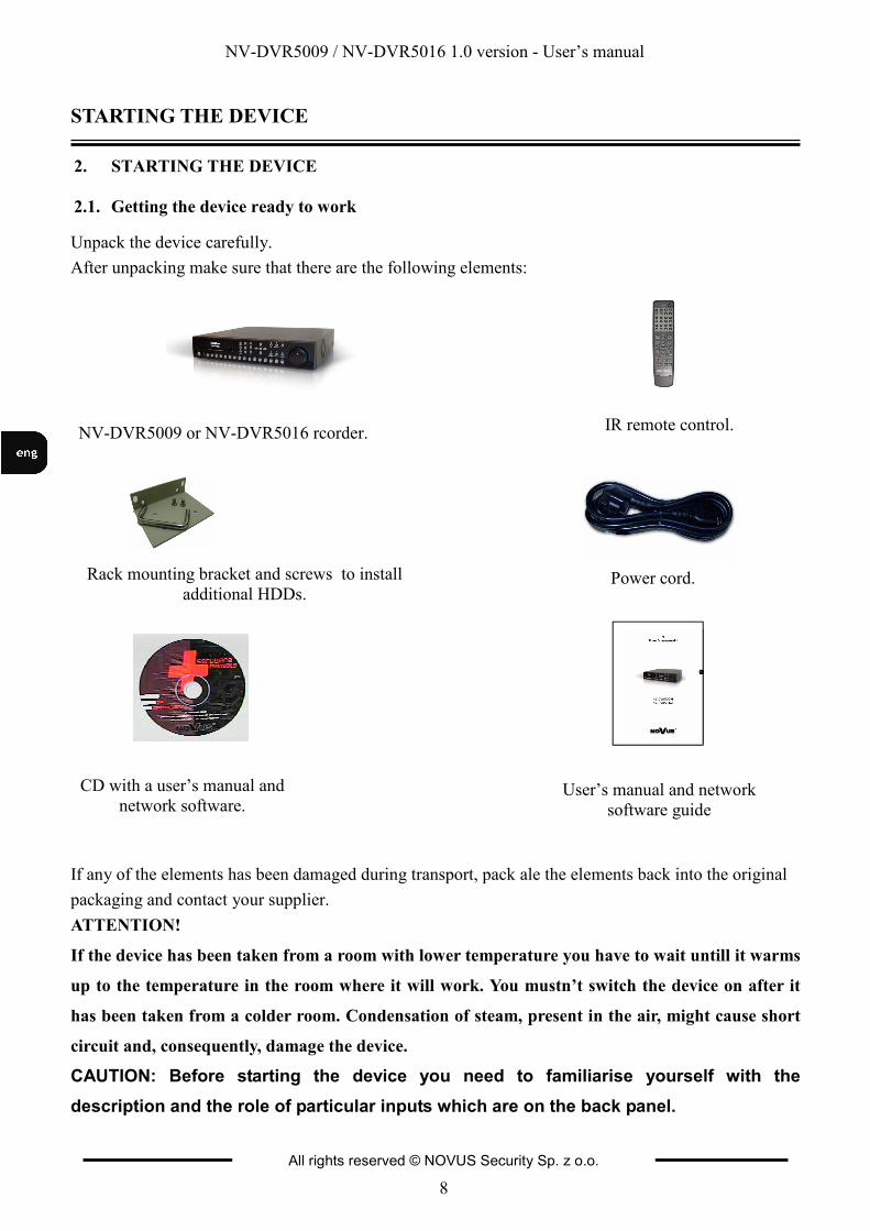
Unpack the device carefully.
After unpacking make sure that there are the following elements:
If any of the elements has been damaged during transport, pack ale the elements back into the original
packaging and contact your supplier.
ATTENTION!
If the device has been taken from a room with lower temperature you have to wait untill it warms
up to the temperature in the room where it will work. You mustn’t switch the device on after it
has been taken from a colder room. Condensation of steam, present in the air, might cause short
circuit and, consequently, damage the device.
CAUTION: Before starting the device you need to familiarise yourself with the
description and the role of particular inputs which are on the back panel.
NV-DVR5009 or NV-DVR5016 rcorder. IR remote control.
Rack mounting bracket and screws to install
additional HDDs. Power cord.
CD with a user’s manual and
network software.
STARTING THE DEVICE
User’s manual and network
software guide
NV-DVR5009 / NV-DVR5016 1.0 version - User’s manual
All rights reserved © NOVUS Security Sp. z o.o.
9
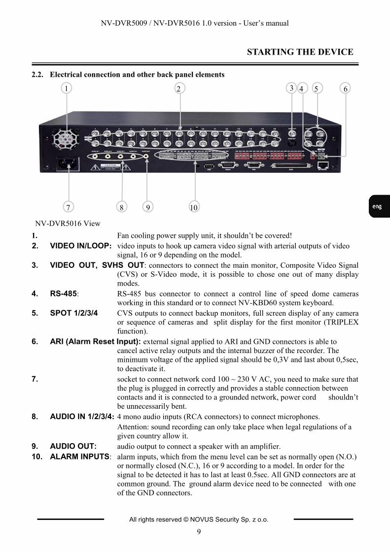
1. Fan cooling power supply unit, it shouldn’t be covered!
2. VIDEO IN/LOOP: video inputs to hook up camera video signal with arterial outputs of video signal, 16 or 9 depending on the model.
3. VIDEO OUT, SVHS OUT: connectors to connect the main monitor, Composite Video Signal (CVS) or S-Video mode, it is possible to chose one out of many display
modes.
4. RS-485: RS-485 bus connector to connect a control line of speed dome cameras
working in this standard or to connect NV-KBD60 system keyboard.
5. SPOT 1/2/3/4 CVS outputs to connect backup monitors, full screen display of any camera
or sequence of cameras and split display for the first monitor (TRIPLEX
function).
6. ARI (Alarm Reset Input): external signal applied to ARI and GND connectors is able to cancel active relay outputs and the internal buzzer of the recorder. The
minimum voltage of the applied signal should be 0,3V and last about 0,5sec,
to deactivate it.
7. socket to connect network cord 100 ~ 230 V AC, you need to make sure that
the plug is plugged in correctly and provides a stable connection between
contacts and it is connected to a grounded network, power cord shouldn’t
be unnecessarily bent.
8. AUDIO IN 1/2/3/4: 4 mono audio inputs (RCA connectors) to connect microphones.
Attention: sound recording can only take place when legal regulations of a
given country allow it.
9. AUDIO OUT: audio output to connect a speaker with an amplifier.
10. ALARM INPUTS: alarm inputs, which from the menu level can be set as normally open (N.O.) or normally closed (N.C.), 16 or 9 according to a model. In order for the
signal to be detected it has to last at least 0.5sec. All GND connectors are at
common ground. The ground alarm device need to be connected with one
of the GND connectors.
2.2. Electrical connection and other back panel elements
NV-DVR5016 View
STARTING THE DEVICE
7
3
5 4 2 1 6
8 9 10

NV-DVR5009 / NV-DVR5016 1.0 version - User’s manual
All rights reserved © NOVUS Security Sp. z o.o.
10
11. USB Port to USB ports of the device (one port in the back panel and two in the front panel) you can connect external HHDs, external CD-RW recorders or Flash
memory for archiving. The cord between a port and the device shouldn't be
longer than 30 cm. Mouse (not included in the set) with USB connector can
be connected to the device and used for navigating recorder’s menu. Post
Script printer can be connected to a chosen USB port. In the playback mode
chosen images can be printed. To this, through a converter, you can
connect devices generating information in the form of ASCII codes (cash
registers, cash machines).
12. RS-232 port : it is to connect external modem for remote preview, to connect external keyboard (optional) or devices generating information in the form of ASCII
codes (cash registers, cash machines).
Attention: Cord used for connecting to RS-232 port is not included with the
set. Make sure that the cord you have is appropriate. (DB9S female
connector).
13. VGA output to connect the main monitor in the VGA mode (computer mode). You need to use signal cord provided with the monitor. In the front panel
press and hold for minimum 5 sec the DISPLAY button, in order to switch
displaying between BNC - S-VHS connectors and VGA connector. During
switching camera images might not be recorded for the period of more or
less 3 sec.
14. ALARM OUTPUTS recorder can activate external devices such as buzzers, halogen lamps, sirens etc. by means of 16 or 9, (depending on the model) outputs - open
collector type. Transmitter’s load capacity is 5mA@12V and 30mA@ 5V.
NV-DVR5016 View
STARTING THE DEVICE
11 12 13 14
NV-DVR5009 / NV-DVR5016 1.0 version - User’s manual
All rights reserved © NOVUS Security Sp. z o.o.
11
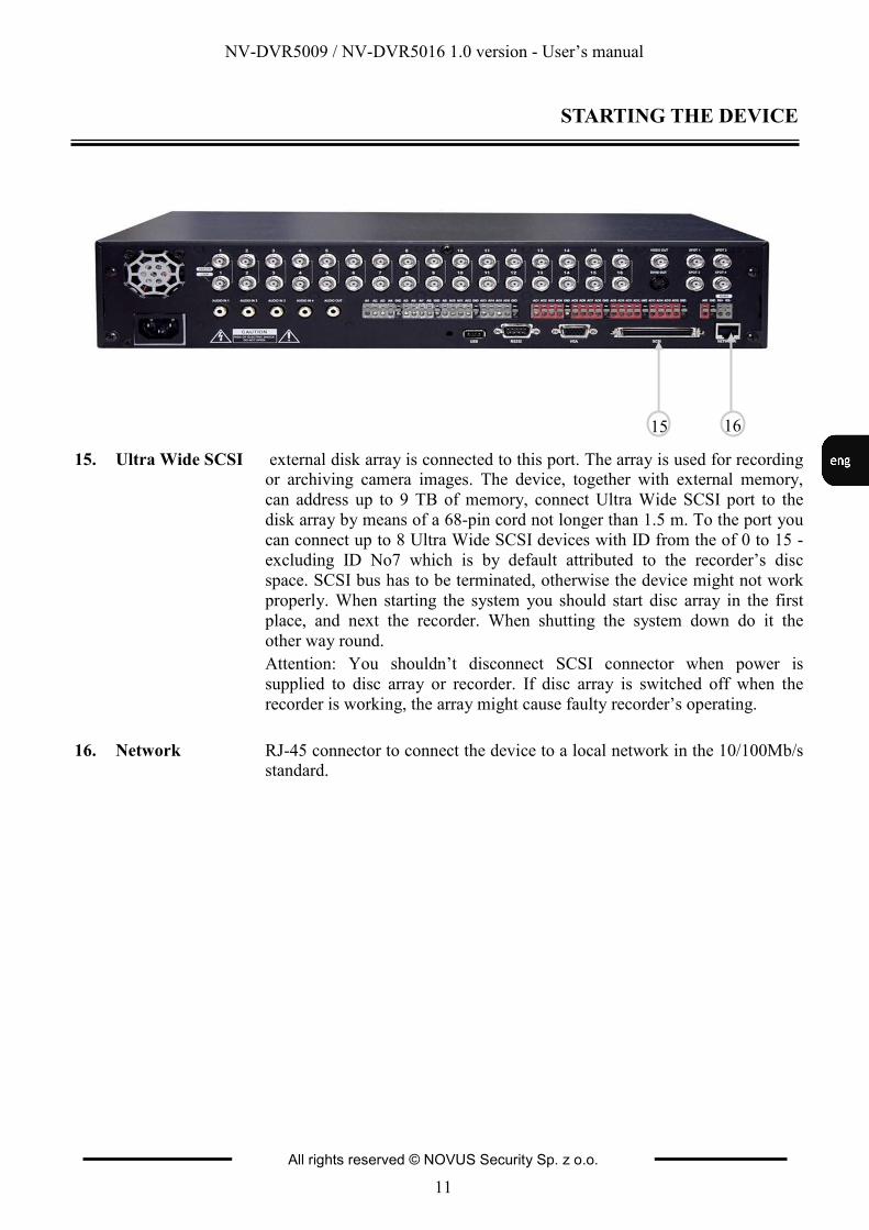
15. Ultra Wide SCSI external disk array is connected to this port. The array is used for recording or archiving camera images. The device, together with external memory,
can address up to 9 TB of memory, connect Ultra Wide SCSI port to the
disk array by means of a 68-pin cord not longer than 1.5 m. To the port you
can connect up to 8 Ultra Wide SCSI devices with ID from the of 0 to 15 -
excluding ID No7 which is by default attributed to the recorder’s disc
space. SCSI bus has to be terminated, otherwise the device might not work
properly. When starting the system you should start disc array in the first
place, and next the recorder. When shutting the system down do it the
other way round.
Attention: You shouldn’t disconnect SCSI connector when power is
supplied to disc array or recorder. If disc array is switched off when the
recorder is working, the array might cause faulty recorder’s operating.
16. Network RJ-45 connector to connect the device to a local network in the 10/100Mb/s standard.
STARTING THE DEVICE
15 16
NV-DVR5009 / NV-DVR5016 1.0 version - User’s manual
All rights reserved © NOVUS Security Sp. z o.o.
12
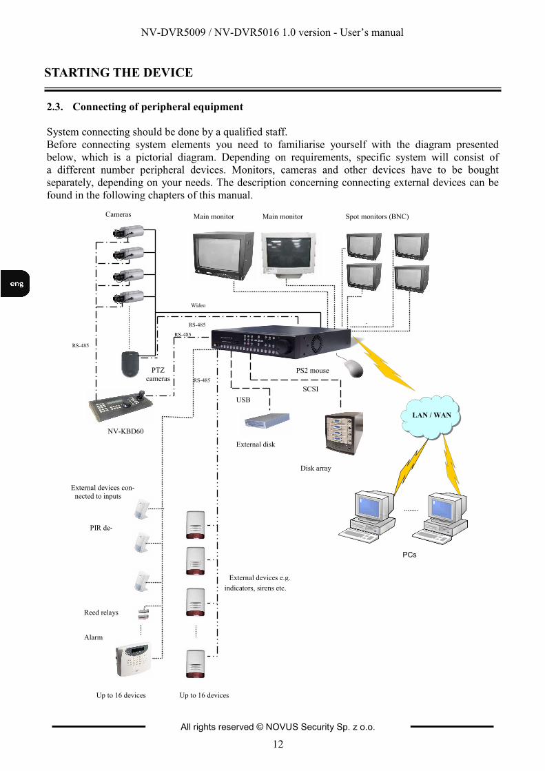
2.3. Connecting of peripheral equipment
System connecting should be done by a qualified staff.
Before connecting system elements you need to familiarise yourself with the diagram presented
below, which is a pictorial diagram. Depending on requirements, specific system will consist of
a different number peripheral devices. Monitors, cameras and other devices have to be bought
separately, depending on your needs. The description concerning connecting external devices can be
found in the following chapters of this manual.
STARTING THE DEVICE
LAN / WAN
Main monitor Spot monitors (BNC) Main monitor
RS-485
Wideo
Cameras
PTZ
cameras
PCs
USB
SCSI
Disk array
RS-485
NV-KBD60
External devices con-
nected to inputs
PIR de-
Reed relays
Alarm
External devices e.g.
podłączone do wyjść alarmowych
indicators, sirens etc.
External disk
PS2 mouse
RS-485
RS-485
Up to 16 devices Up to 16 devices
NV-DVR5009 / NV-DVR5016 1.0 version - User’s manual
All rights reserved © NOVUS Security Sp. z o.o.
13
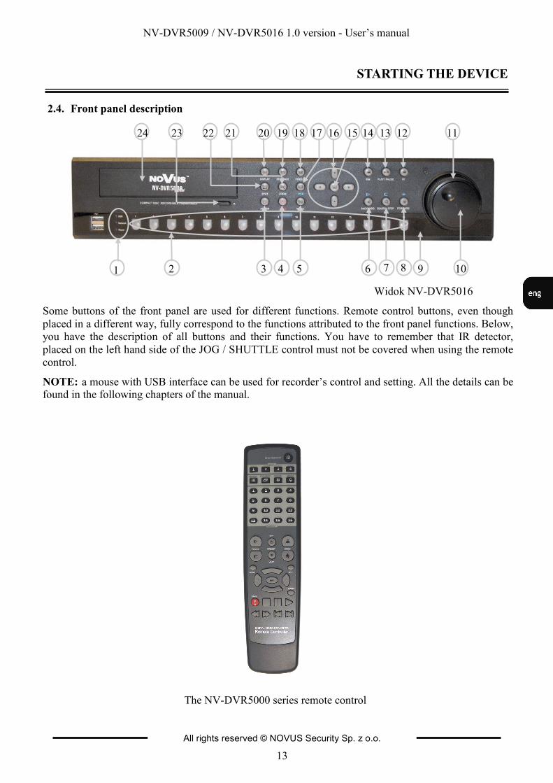
2.4. Front panel description
Widok NV-DVR5016
STARTING THE DEVICE
Some buttons of the front panel are used for different functions. Remote control buttons, even though
placed in a different way, fully correspond to the functions attributed to the front panel functions. Below,
you have the description of all buttons and their functions. You have to remember that IR detector,
placed on the left hand side of the JOG / SHUTTLE control must not be covered when using the remote
control.
NOTE: a mouse with USB interface can be used for recorder’s control and setting. All the details can be found in the following chapters of the manual.
The NV-DVR5000 series remote control
1 2 3 4 5 6 7 8 9 10
11 12 13 14 15 16 17 18 19 20 21 22 23 24

NV-DVR5009 / NV-DVR5016 1.0 version - User’s manual
All rights reserved © NOVUS Security Sp. z o.o.
14
1. LED Flickering of a green HDD LED (light-emitting diode) means that a process of recording or searching / playback is in progress.
Flickering of a green NETWORK LED means that the device is
connected to Ethernet or external modem. Flickering of a green
POWER LED means that the power supply is on.
2. CHANNEL BUTTONS Pressing one of the channel buttons means that an image from a camera connected to a given channel is displayed. It is a full
screen view. Channel buttons are used for setting and putting in
password. Holding any of the channel buttons for 3 seconds allows
you to enter image setting menu (brightness, contrast, saturation,
hue).
3. ALARM Pressing ALARM button causes cancelling of internal buzzer and active relay outputs. By pressing ALARM button in the “live”
mode you enter event register. This function can be protected by
a password.
4. PANIC Pressing the PANIC button starts recoding of all camera channels, and displays on the main screen.
5. MENU Pressing MENU button allows you to enter recorder’s settings. A menu is displayed on the screen. Its description can be found in
the following chapters of this manual.
6. BACKWARD Pressing the BACKWARD button goes to the previous image. The button on the front panel is also used for Near Focus in the PTZ
mode.
7. SEARCH / STOP Pressing the SEARCH/STOP button enters the Search menu. Pressing the button again exits the Search mode. You will need to
log into the system with a qualified user to enter the Search mode
from the Live Monitoring mode. The button is also used for Far
Focus while in the PTZ mode.
8. FORWARD Pressing the FORWARD button goes to the next image. The button on the front panel is also used to load a Preset View in the
PTZ mode.
9. IR DETECTOR IR window receiver. It receives infra-red beams emitted by the remote control. Do not cover.
STARTING THE DEVICE
NV-DVR5009 / NV-DVR5016 1.0 version - User’s manual
All rights reserved © NOVUS Security Sp. z o.o.
15
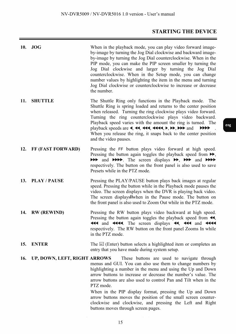
10. JOG When in the playback mode, you can play video forward image- by-image by turning the Jog Dial clockwise and backward image-
by-image by turning the Jog Dial counterclockwise. When in the
PIP mode, you can make the PIP screen smaller by turning the
Jog Dial clockwise and larger by turning the Jog Dial
counterclockwise. When in the Setup mode, you can change
number values by highlighting the item in the menu and turning
Jog Dial clockwise or counterclockwise to increase or decrease
the number.
11. SHUTTLE The Shuttle Ring only functions in the Playback mode. The Shuttle Ring is spring loaded and returns to the center position
when released. Turning the ring clockwise plays video forward.
Turning the ring counterclockwise plays video backward.
Playback speed varies with the amount the ring is turned. The
playback speeds are , , , , , , and .
When you release the ring, it snaps back to the center position
and the video pauses.
12. FF (FAST FORWARD) Pressing the FF button plays video forward at high speed. Pressing the button again toggles the playback speed from ,
and . The screen displays , and
respectively. The button on the front panel is also used to save
Presets while in the PTZ mode.
13. PLAY / PAUSE Pressing the PLAY/PAUSE button plays back images at regular speed. Pressing the button while in the Playback mode pauses the
video. The screen displays when the DVR is playing back video.
The screen displays when in the Pause mode. The button on
the front panel is also used to Zoom Out while in the PTZ mode.
14. RW (REWIND) Pressing the RW button plays video backward at high speed. Pressing the button again toggles the playback speed from ,
and . The screen displays , and
respectively. The RW button on the front panel Zooms In while
in the PTZ mode.
15. ENTER The (Enter) button selects a highlighted item or completes an entry that you have made during system setup.
16. UP, DOWN, LEFT, RIGHT ARROWS These buttons are used to navigate through menus and GUI. You can also use them to change numbers by
highlighting a number in the menu and using the Up and Down
arrow buttons to increase or decrease the number’s value. The
arrow buttons are also used to control Pan and Tilt when in the
PTZ mode.
When in the PIP display format, pressing the Up and Down
arrow buttons moves the position of the small screen counter-
clockwise and clockwise, and pressing the Left and Right
buttons moves through screen pages.
STARTING THE DEVICE

NV-DVR5009 / NV-DVR5016 1.0 version - User’s manual
All rights reserved © NOVUS Security Sp. z o.o.
16
17. PTZ Pressing the PTZ button enters the PTZ (Pan/Tilt/Zoom) mode which allows you to control properly configured cameras.
18. FREEZE Pressing the FREEZE button freezes the current live screen.
19. SEQUENCE When in the live mode, pressing the SEQUENCE button displays live channels sequentially.
20. DISPLAY The DISPLAY button has two functions. First, it toggles between different display formats. The available formats are: full,
4x4, 3x3, 2x2 and PIP. Second, pressing and holding the button
for 3 seconds or longer it will switch the video output between
Video Out (BNC or SVHS Out) and VGA Out.
21. ZOOM Pressing the ZOOM button zooms the current image on the screen. A PIP with a rectangle temporarily displays showing what area of
the screen has been enlarged. You can use the arrow buttons to
move the rectangle to another area. Pressing the (Enter)
button toggles the zoom size between 2x, 3x and 4x.
22. SPOT Pressing the SPOT button allows you to select which cameras will display on the four Spot Monitors. After selecting the
monitor you can opt to have that Spot Monitor displays a single
camera or all cameras sequentially. The infrared remote control
allows you to go directly to the individual Spot Monitor menus.
23. EJECT CD-RW drive eject button.
24. INSERT TAB Tab protecting CD-RW drive.
ID BUTTON ON REMOTE CONTROL
If a DVR System ID is set to 0, the infrared remote control will control that DVR without any
additional operations. (Refer to the System Information setup screen in this chapter for further
information on setting the System ID). If the system ID is 1 to 16, you must to press the ID button on
the remote control and then press the number button (1 to 16) in order to control that DVR. If the
System ID of two or more DVRs is set to 0, those DVRs will all react to the infrared remote control at
the same time.
TURNING ON THE POWER
Connecting the power cord to the DVR turns on the unit. The unit takes approximately 60
seconds to initialize.
STARTING THE DEVICE
NV-DVR5009 / NV-DVR5016 1.0 version - User’s manual
All rights reserved © NOVUS Security Sp. z o.o.
17
RECORDER’S MENU
3. RECORDER’S MENU
NV-DVR5009 and NV-DVR50016 recorders have multilevel menus displayed on the screen.
The menu is multilingual. Depending on the implemented firmware version, it is displayed in English,
German, Spanish, French and Italian, or English, Polish, Russian, Hungarian and Czech.
The only difference between 9– and 16-channel versions is in the amount of channels. There are 9 or
16 vision channels, alarm inputs etc.
Before using your DVR for the first time, you need to establish the initial settings. This includes items
such as time and date, display language, camera, audio, remote control, record mode, network and
password. Your DVR can be set up using various screens and dialog boxes. Throughout the screens you will see . Highlighting the and pressing the button gives you the opportunity to reset that screen to its
default settings.
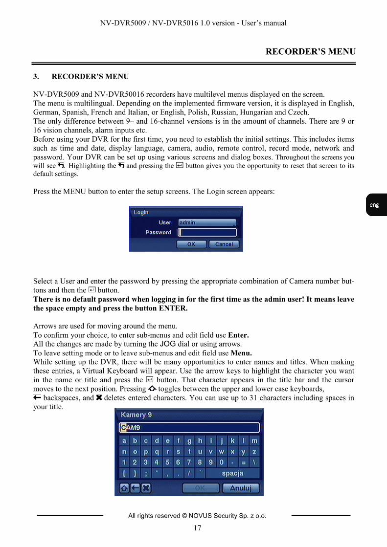
Press the MENU button to enter the setup screens. The Login screen appears:
Select a User and enter the password by pressing the appropriate combination of Camera number but-
tons and then the button.
There is no default password when logging in for the first time as the admin user! It means leave
the space empty and press the button ENTER.
Arrows are used for moving around the menu.
To confirm your choice, to enter sub-menus and edit field use Enter. All the changes are made by turning the JOG dial or using arrows. To leave setting mode or to leave sub-menus and edit field use Menu. While setting up the DVR, there will be many opportunities to enter names and titles. When making
these entries, a Virtual Keyboard will appear. Use the arrow keys to highlight the character you want
in the name or title and press the button. That character appears in the title bar and the cursor
moves to the next position. Pressing toggles between the upper and lower case keyboards,
backspaces, and deletes entered characters. You can use up to 31 characters including spaces in
your title.
NV-DVR5009 / NV-DVR5016 1.0 version - User’s manual
All rights reserved © NOVUS Security Sp. z o.o.
18
3.1. System menu
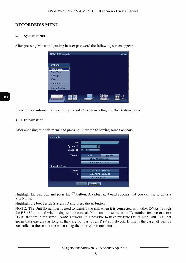
After pressing Menu and putting in user password the following screen appears:
There are six sub-menus concerning recorder’s system settings in the System menu.
3.1.1. Information
After choosing this sub-menu and pressing Enter the following screen appears:
Highlight the Site box and press the button. A virtual keyboard appears that you can use to enter a
Site Name.
Highlight the box beside System ID and press the button.
NOTE: The Unit ID number is used to identify the unit when it is connected with other DVRs through the RS-485 port and when using remote control. You cannot use the same ID number for two or more
DVRs that are in the same RS-485 network. It is possible to have multiple DVRs with Unit ID 0 that
are in the same area as long as they are not part of an RS-485 network. If this is the case, all will be
controlled at the same time when using the infrared remote control.
RECORDER’S MENU

NV-DVR5009 / NV-DVR5016 1.0 version - User’s manual
All rights reserved © NOVUS Security Sp. z o.o.
19
Highlight the box beside Language and press button. A drop-down menu displays the available
languages. Highlight the desired language and press the button.
To upgrade the software, connect a USB device containing upgrade package file to the DVR. Highlight
Upgrade… and press the button. The Upgrade screen appears. The screen displays the upgrade
package file names that are available. The “.rui” indicates that the file is for software upgrades and
“.ofi” indicates that the file is for optical drive’s firmware upgrades. Select the desired file and press
the button. Highlighting the Install button and pressing the button will install the selected software
package. Highlighting the Cancel button and pressing the button will close the window without
upgrading the software. If the upgrade package file is not installed on the DVR properly, you will get
an error message. The system restarts automatically after completing the upgrade.
NOTE: The Upgrade button will be deactivated if the hard disk drive has not been formatted as it requires the space for temporary files when upgrading the system.
CAUTION: The USB device must be FAT16 or FAT32 format.
3.1.1.1. System log
Highlight Show System Log… and press the button to display the System Log
The System Log screen lists system activities (up to 10,000 from the latest) that have occurred along
with the time and date. The icon will be displayed in the last column for system activities of the
remote site. You can scroll through the log pages by using the Up and Down arrows, or you can go
directly to a log page by entering the log page number in the box at the bottom left of the screen.
Highlight Close and press the button to exit the screen.
RECORDER’S MENU
NV-DVR5009 / NV-DVR5016 1.0 version - User’s manual
All rights reserved © NOVUS Security Sp. z o.o.
20
RECORDER’S MENU
3.1.1.2 System status
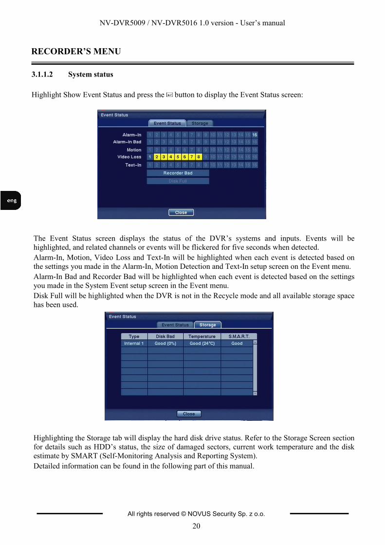
Highlight Show Event Status and press the button to display the Event Status screen:
The Event Status screen displays the status of the DVR’s systems and inputs. Events will be
highlighted, and related channels or events will be flickered for five seconds when detected.
Alarm-In, Motion, Video Loss and Text-In will be highlighted when each event is detected based on
the settings you made in the Alarm-In, Motion Detection and Text-In setup screen on the Event menu.
Alarm-In Bad and Recorder Bad will be highlighted when each event is detected based on the settings
you made in the System Event setup screen in the Event menu.
Disk Full will be highlighted when the DVR is not in the Recycle mode and all available storage space
has been used.
Highlighting the Storage tab will display the hard disk drive status. Refer to the Storage Screen section
for details such as HDD’s status, the size of damaged sectors, current work temperature and the disk
estimate by SMART (Self-Monitoring Analysis and Reporting System).
Detailed information can be found in the following part of this manual.

NV-DVR5009 / NV-DVR5016 1.0 version - User’s manual
All rights reserved © NOVUS Security Sp. z o.o.
21
RECORDER’S MENU
3.1.1.3. Recording range
In the recording range section you can find time frames of the recorded camera images.
Highlighting Clear All Data… and pressing the button will clear all video data.
You will be asked to verify that you wish to clear all data before the DVR erases the video data.
Clear All Data… will not clear the System Log.
3.1.2. Date / time
Highlight Date/Time in the System menu and press the button. The Date/Time setup screen appears.
Highlight the first box beside Date and press the button. The individual sections of the date will
highlight. Use the Up and Down arrow buttons to change the number. Use the Left and Right arrow
buttons to move between month, date and year. Once you have the correct date, press the button.
Highlight the Format box beside Date and press the button. Select from the three available date
formats and press the button to save your selected format.
NOTE: The clock will not start running until you have highlighted Save and pressed the button.
Highlight Use Daylight Saving Time and press the button. Pressing the button toggles between
On and Off.
Highlight the Holiday tab, and the Holiday setup screen appears.
NV-DVR5009 / NV-DVR5016 1.0 version - User’s manual
All rights reserved © NOVUS Security Sp. z o.o.
22
RECORDER’S MENU
NOTE: Holidays that do not fall on the same date each year should be updated once the current year’s holiday has passed.
You can set up holidays by highlighting + and pressing the button. The current date appears.
Highlight the month and day and change them by using the Up and Down arrow buttons. Press the
button to add the date. Dates can be deleted by highlighting the beside the date and pressing the
button.
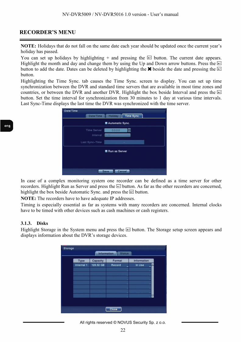
Highlighting the Time Sync. tab causes the Time Sync. screen to display. You can set up time
synchronization between the DVR and standard time servers that are available in most time zones and
countries, or between the DVR and another DVR. Highlight the box beside Interval and press the
button. Set the time interval for synchronization from 30 minutes to 1 day at various time intervals.
Last Sync-Time displays the last time the DVR was synchronized with the time server.
In case of a complex monitoring system one recorder can be defined as a time server for other
recorders. Highlight Run as Server and press the button. As far as the other recorders are concerned,
highlight the box beside Automatic Sync. and press the button.
NOTE: The recorders have to have adequate IP addresses.
Timing is especially essential as far as systems with many recorders are concerned. Internal clocks
have to be timed with other devices such as cash machines or cash registers.
3.1.3. Disks
Highlight Storage in the System menu and press the button. The Storage setup screen appears and
displays information about the DVR’s storage devices.
NV-DVR5009 / NV-DVR5016 1.0 version - User’s manual
All rights reserved © NOVUS Security Sp. z o.o.
23
RECORDER’S MENU
The information in the Type column describes the storage device (internal disk, external disk with
USB interface).
The capacity of the storage device is displayed in the Capacity column.
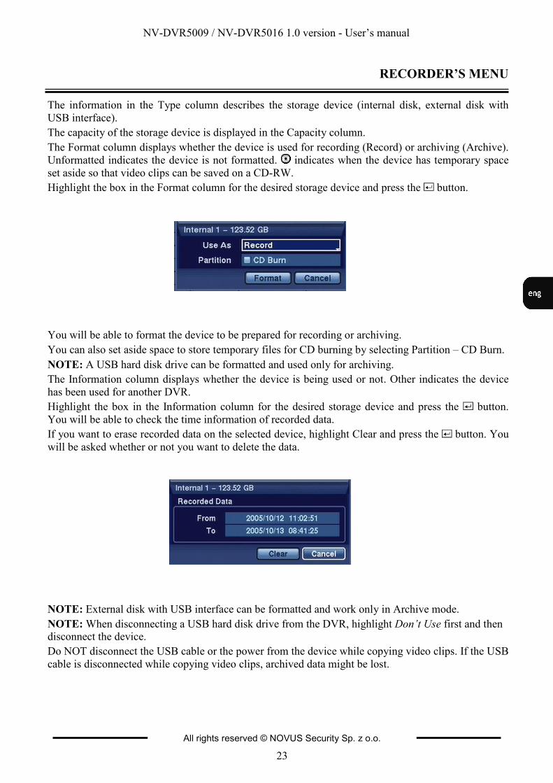
The Format column displays whether the device is used for recording (Record) or archiving (Archive).
Unformatted indicates the device is not formatted. indicates when the device has temporary space
set aside so that video clips can be saved on a CD-RW.
Highlight the box in the Format column for the desired storage device and press the button.
You will be able to format the device to be prepared for recording or archiving.
You can also set aside space to store temporary files for CD burning by selecting Partition – CD Burn.
NOTE: A USB hard disk drive can be formatted and used only for archiving.
The Information column displays whether the device is being used or not. Other indicates the device
has been used for another DVR.
Highlight the box in the Information column for the desired storage device and press the button.
You will be able to check the time information of recorded data.
If you want to erase recorded data on the selected device, highlight Clear and press the button. You
will be asked whether or not you want to delete the data.
NOTE: External disk with USB interface can be formatted and work only in Archive mode.
NOTE: When disconnecting a USB hard disk drive from the DVR, highlight Don’t Use first and then disconnect the device.
Do NOT disconnect the USB cable or the power from the device while copying video clips. If the USB
cable is disconnected while copying video clips, archived data might be lost.
NV-DVR5009 / NV-DVR5016 1.0 version - User’s manual
All rights reserved © NOVUS Security Sp. z o.o.
24
RECORDER’S MENU
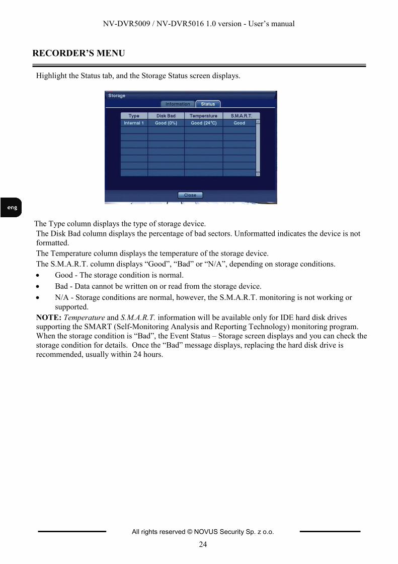
Highlight the Status tab, and the Storage Status screen displays.
The Type column displays the type of storage device.
The Disk Bad column displays the percentage of bad sectors. Unformatted indicates the device is not
formatted.
The Temperature column displays the temperature of the storage device.
The S.M.A.R.T. column displays “Good”, “Bad” or “N/A”, depending on storage conditions.
• Good - The storage condition is normal.
• Bad - Data cannot be written on or read from the storage device.
• N/A - Storage conditions are normal, however, the S.M.A.R.T. monitoring is not working or
supported.
NOTE: Temperature and S.M.A.R.T. information will be available only for IDE hard disk drives supporting the SMART (Self-Monitoring Analysis and Reporting Technology) monitoring program.
When the storage condition is “Bad”, the Event Status – Storage screen displays and you can check the
storage condition for details. Once the “Bad” message displays, replacing the hard disk drive is
recommended, usually within 24 hours.
NV-DVR5009 / NV-DVR5016 1.0 version - User’s manual
All rights reserved © NOVUS Security Sp. z o.o.
25
RECORDER’S MENU
3.1.4. Users
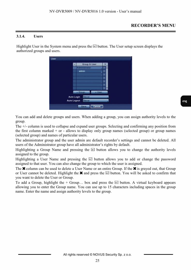
Highlight User in the System menu and press the button. The User setup screen displays the
authorized groups and users.
You can add and delete groups and users. When adding a group, you can assign authority levels to the
group.
The +/- column is used to collapse and expand user groups. Selecting and confirming any position from
the first column marked + or - allows to display only group names (selected group) or group names
(selected group) and names of particular users.
The administrator group and the user admin are default recorder’s settings and cannot be deleted. All
users of the Administrator group have all administrator’s rights by default.
Highlighting a Group Name and pressing the button allows you to change the authority levels
assigned to the group.
Highlighting a User Name and pressing the button allows you to add or change the password
assigned to that user. You can also change the group to which the user is assigned.
The column can be used to delete a User Name or an entire Group. If the is grayed out, that Group
or User cannot be deleted. Highlight the and press the button. You will be asked to confirm that
you want to delete the User or Group.
To add a Group, highlight the + Group… box and press the button. A virtual keyboard appears
allowing you to enter the Group name. You can use up to 15 characters including spaces in the group
name. Enter the name and assign authority levels to the group.
NV-DVR5009 / NV-DVR5016 1.0 version - User’s manual
All rights reserved © NOVUS Security Sp. z o.o.
26
RECORDER’S MENU
A group of users can obtain the following rights:
• Shutdown — The user can shut the system down on a local system.
• Upgrade — The user can upgrade the software on a local system or a PC running RAS
• System Time Change — The user can change the system date and time on a local system or a PC
running RAS.
• Data Clear — The user can clear all video data or format disks on a local system or a PC running
RAS.
• Setup — The user without Setup authority cannot establish any system settings excluding system
shutdown and logout on a local system or a PC running RAS.
• Color Control — The user can control brightness, contrast, hue and saturation for cameras on a
local system or a PC running RAS.
• PTZ Control — The user can control the PTZ camera on a local system or a PC running RAS.
• Alarm-Out Control — The user can reset the DVR’s outputs including the internal buzzer during
an alarm by pressing the ALARM button on a local system or alarm-out control button on a PC
running RAS.
• Covert Camera View — The user can view video from cameras set as Covert while in the Live
Monitoring or Search mode on a local system or a PC running RAS.
• System Check — The user can view the remote system status or check the remote system status
as a batch process on a PC running RAS.
• Record Setup — The user can establish all Record settings on a local system or a PC running
RAS.
• Search — The user can access the Search mode on a local system or a PC running RAS.
• Clip-Copy — The user can copy video clips on a local system or a PC running RAS, and save
video data in an AVI, bitmap or JPEG file format.
Highlighting the box beside Auto Login allows you to select a User to be automatically logged in when
the DVR is powered up.
Highlighting the box beside Auto Logout allows you to select from a list of times that the user will be
automatically logged out. The options are: Never, 1 min., 3 min., 5 min., 10 min., 15 min., 20 min., 25
min., 30 min. and 1 hr.
NV-DVR5009 / NV-DVR5016 1.0 version - User’s manual
All rights reserved © NOVUS Security Sp. z o.o.
27
RECORDER’S MENU
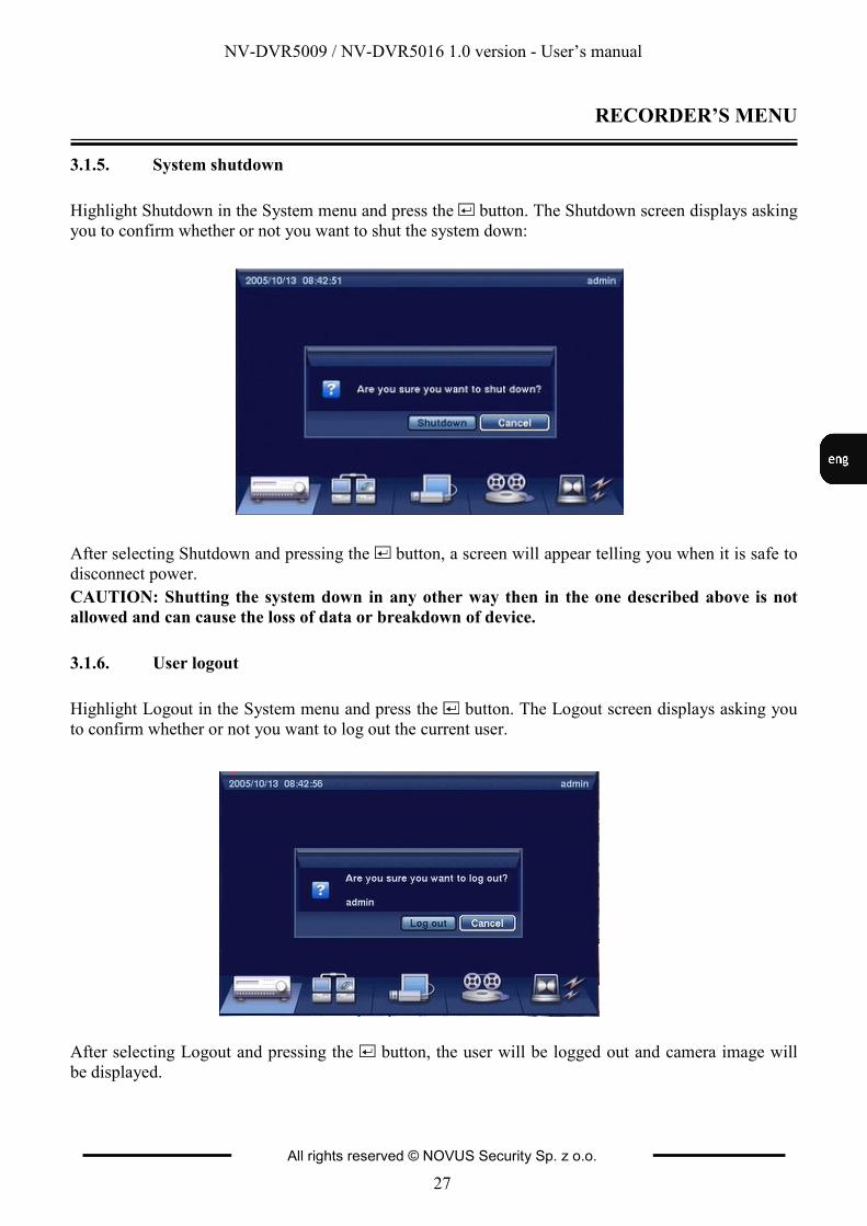
3.1.5. System shutdown
Highlight Shutdown in the System menu and press the button. The Shutdown screen displays asking
you to confirm whether or not you want to shut the system down:
After selecting Shutdown and pressing the button, a screen will appear telling you when it is safe to
disconnect power.
CAUTION: Shutting the system down in any other way then in the one described above is not
allowed and can cause the loss of data or breakdown of device.
3.1.6. User logout
Highlight Logout in the System menu and press the button. The Logout screen displays asking you
to confirm whether or not you want to log out the current user.
After selecting Logout and pressing the button, the user will be logged out and camera image will
be displayed.
NV-DVR5009 / NV-DVR5016 1.0 version - User’s manual
All rights reserved © NOVUS Security Sp. z o.o.
28
RECORDER’S MENU
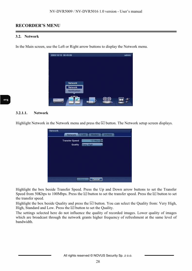
3.2. Network
In the Main screen, use the Left or Right arrow buttons to display the Network menu.
3.2.1.1. Network
Highlight Network in the Network menu and press the button. The Network setup screen displays.
Highlight the box beside Transfer Speed. Press the Up and Down arrow buttons to set the Transfer
Speed from 50Kbps to 100Mbps. Press the button to set the transfer speed. Press the button to set
the transfer speed.
Highlight the box beside Quality and press the button. You can select the Quality from: Very High,
High, Standard and Low. Press the button to set the Quality.
The settings selected here do not influence the quality of recorded images. Lower quality of images
which are broadcast through the network grants higher frequency of refreshment at the same level of
bandwidth.
NV-DVR5009 / NV-DVR5016 1.0 version - User’s manual
All rights reserved © NOVUS Security Sp. z o.o.
29
RECORDER’S MENU
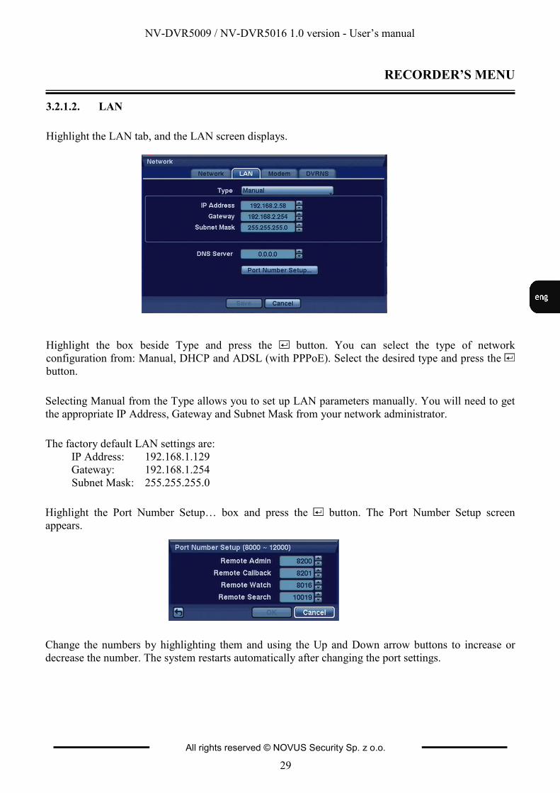
3.2.1.2. LAN
Highlight the LAN tab, and the LAN screen displays.
Highlight the box beside Type and press the button. You can select the type of network
configuration from: Manual, DHCP and ADSL (with PPPoE). Select the desired type and press the
button.
Selecting Manual from the Type allows you to set up LAN parameters manually. You will need to get
the appropriate IP Address, Gateway and Subnet Mask from your network administrator.
The factory default LAN settings are:
IP Address: 192.168.1.129
Gateway: 192.168.1.254
Subnet Mask: 255.255.255.0
Highlight the Port Number Setup… box and press the button. The Port Number Setup screen
appears.
Change the numbers by highlighting them and using the Up and Down arrow buttons to increase or
decrease the number. The system restarts automatically after changing the port settings.
NV-DVR5009 / NV-DVR5016 1.0 version - User’s manual
All rights reserved © NOVUS Security Sp. z o.o.
30
RECORDER’S MENU
The factory default Port settings are:
Remote Admin: 8200
Remote Call-back: 8201
Remote Watch: 8016
Remote Search: 10019
NOTE: Do NOT use the same port number for two different programs, otherwise, the DVR cannot be connected with a PC running RAS.
When changing the port settings, you must change the port settings on the PC running RAS as well.
Refer to the RAS manual for details.
For the ADSL network connection with PPPoE protocol you need to manually configure connection
parameters as far as ID number and passwords are concerned.
NOTE: The ADSL and modem cannot be configured at the same time. If the DVR is configured by modem, the ADSL (with PPPoE) will not be selected.
Entering the ID and Password and highlighting OK reads the current IP address of the DVR configured
by ADSL network. If the DVR is configured by DHCP or ADSL network, the IP address of the DVR
might change whenever the unit is turned on.
3.2.1.3. Modem
When you want to initiate a modem connection please turn to the distributor of the device. The DVR
does not cooperate with the PSTN modems.
3.2.1.4. DVRNS
This option is not activated for the current firmware.
NV-DVR5009 / NV-DVR5016 1.0 version - User’s manual
All rights reserved © NOVUS Security Sp. z o.o.
31
RECORDER’S MENU
3.2.2. Notification
The DVR can be set up to send emails or to contact a computer running RAS (Remote Administration
System) when an event occurs.
3.2.2.1. E-mail
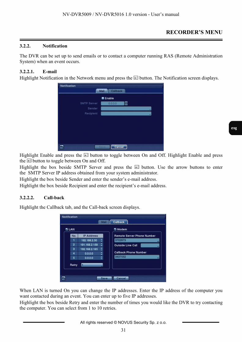
Highlight Notification in the Network menu and press the button. The Notification screen displays.
Highlight Enable and press the button to toggle between On and Off. Highlight Enable and press
the button to toggle between On and Off.
Highlight the box beside SMTP Server and press the button. Use the arrow buttons to enter
the SMTP Server IP address obtained from your system administrator.
Highlight the box beside Sender and enter the sender’s e-mail address.
Highlight the box beside Recipient and enter the recipient’s e-mail address.
3.2.2.2. Call-back
Highlight the Callback tab, and the Call-back screen displays.
When LAN is turned On you can change the IP addresses. Enter the IP address of the computer you
want contacted during an event. You can enter up to five IP addresses.
Highlight the box beside Retry and enter the number of times you would like the DVR to try contacting
the computer. You can select from 1 to 10 retries.
NV-DVR5009 / NV-DVR5016 1.0 version - User’s manual
All rights reserved © NOVUS Security Sp. z o.o.
32
RECORDER’S MENU
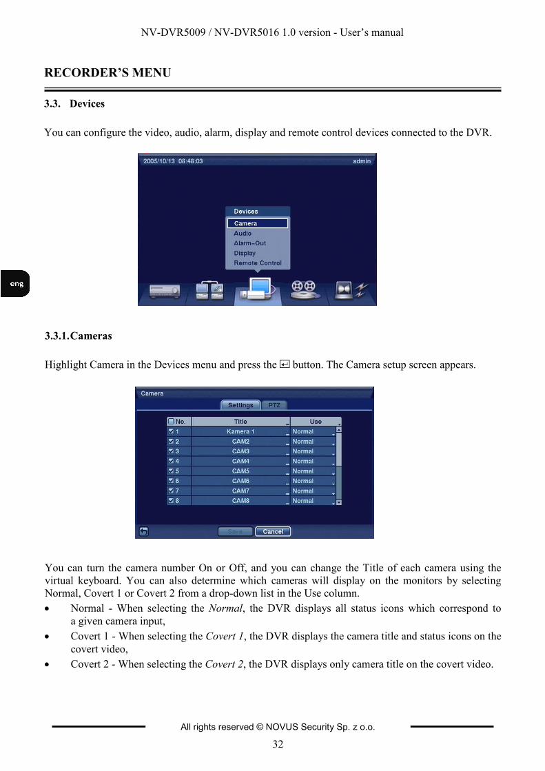
3.3. Devices
You can configure the video, audio, alarm, display and remote control devices connected to the DVR.
3.3.1. Cameras
Highlight Camera in the Devices menu and press the button. The Camera setup screen appears.
You can turn the camera number On or Off, and you can change the Title of each camera using the
virtual keyboard. You can also determine which cameras will display on the monitors by selecting
Normal, Covert 1 or Covert 2 from a drop-down list in the Use column.
• Normal - When selecting the Normal, the DVR displays all status icons which correspond to
a given camera input,
• Covert 1 - When selecting the Covert 1, the DVR displays the camera title and status icons on the
covert video,
• Covert 2 - When selecting the Covert 2, the DVR displays only camera title on the covert video.
NV-DVR5009 / NV-DVR5016 1.0 version - User’s manual
All rights reserved © NOVUS Security Sp. z o.o.
33
RECORDER’S MENU
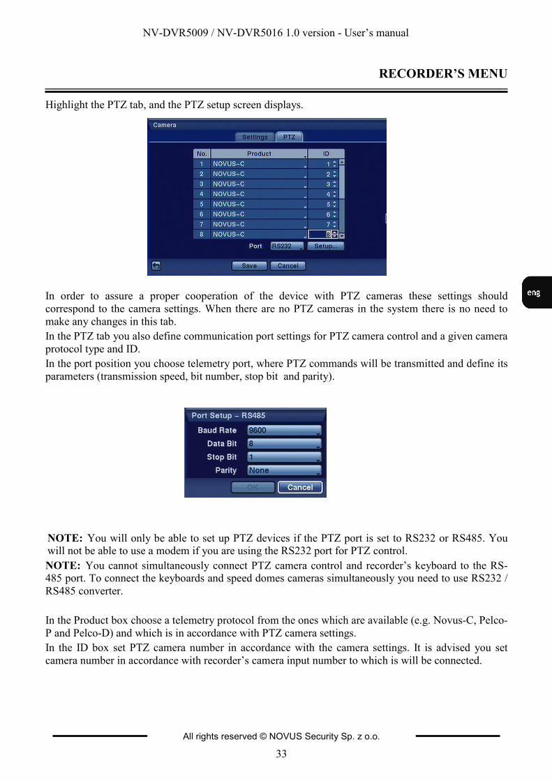
Highlight the PTZ tab, and the PTZ setup screen displays.
In order to assure a proper cooperation of the device with PTZ cameras these settings should
correspond to the camera settings. When there are no PTZ cameras in the system there is no need to
make any changes in this tab.
In the PTZ tab you also define communication port settings for PTZ camera control and a given camera
protocol type and ID.
In the port position you choose telemetry port, where PTZ commands will be transmitted and define its
parameters (transmission speed, bit number, stop bit and parity).
NOTE: You will only be able to set up PTZ devices if the PTZ port is set to RS232 or RS485. You will not be able to use a modem if you are using the RS232 port for PTZ control.
NOTE: You cannot simultaneously connect PTZ camera control and recorder’s keyboard to the RS-485 port. To connect the keyboards and speed domes cameras simultaneously you need to use RS232 /
RS485 converter.
In the Product box choose a telemetry protocol from the ones which are available (e.g. Novus-C, Pelco-
P and Pelco-D) and which is in accordance with PTZ camera settings.
In the ID box set PTZ camera number in accordance with the camera settings. It is advised you set
camera number in accordance with recorder’s camera input number to which is will be connected.
NV-DVR5009 / NV-DVR5016 1.0 version - User’s manual
All rights reserved © NOVUS Security Sp. z o.o.
34
RECORDER’S MENU
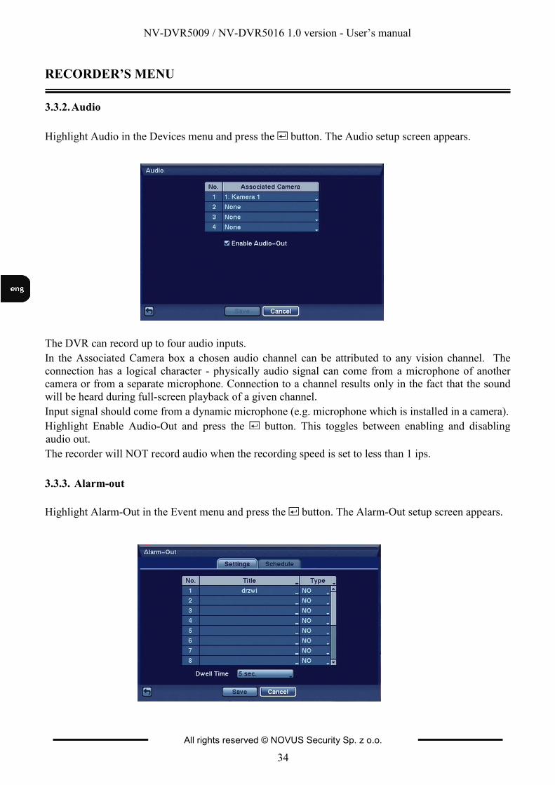
3.3.2. Audio
Highlight Audio in the Devices menu and press the button. The Audio setup screen appears.
The DVR can record up to four audio inputs.
In the Associated Camera box a chosen audio channel can be attributed to any vision channel. The
connection has a logical character - physically audio signal can come from a microphone of another
camera or from a separate microphone. Connection to a channel results only in the fact that the sound
will be heard during full-screen playback of a given channel.
Input signal should come from a dynamic microphone (e.g. microphone which is installed in a camera).
Highlight Enable Audio-Out and press the button. This toggles between enabling and disabling
audio out.
The recorder will NOT record audio when the recording speed is set to less than 1 ips.
3.3.3. Alarm-out
Highlight Alarm-Out in the Event menu and press the button. The Alarm-Out setup screen appears.
NV-DVR5009 / NV-DVR5016 1.0 version - User’s manual
All rights reserved © NOVUS Security Sp. z o.o.
35
RECORDER’S MENU
Each alarm output can be given its own title by highlighting the box under the Title heading and
pressing the button. A virtual keyboard appears allowing you to enter the title.
Highlighting the boxes under the Type heading allows to set the alarm output for NO or NC (normally
open or normally closed).
Highlighting the box beside Dwell Time and pressing the button allows you to set the dwell time of
the alarm output. Dwell times rang from 5 seconds to 15 minutes .
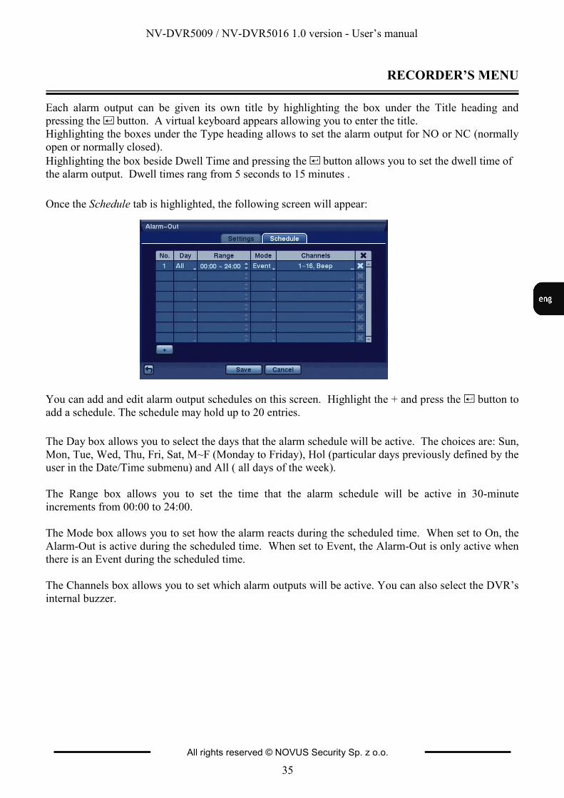
Once the Schedule tab is highlighted, the following screen will appear:
You can add and edit alarm output schedules on this screen. Highlight the + and press the button to
add a schedule. The schedule may hold up to 20 entries.
The Day box allows you to select the days that the alarm schedule will be active. The choices are: Sun,
Mon, Tue, Wed, Thu, Fri, Sat, M~F (Monday to Friday), Hol (particular days previously defined by the
user in the Date/Time submenu) and All ( all days of the week).
The Range box allows you to set the time that the alarm schedule will be active in 30-minute
increments from 00:00 to 24:00.
The Mode box allows you to set how the alarm reacts during the scheduled time. When set to On, the
Alarm-Out is active during the scheduled time. When set to Event, the Alarm-Out is only active when
there is an Event during the scheduled time.
The Channels box allows you to set which alarm outputs will be active. You can also select the DVR’s
internal buzzer.
NV-DVR5009 / NV-DVR5016 1.0 version - User’s manual
All rights reserved © NOVUS Security Sp. z o.o.
36
RECORDER’S MENU
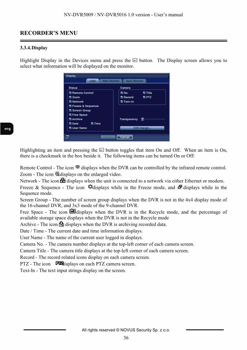
3.3.4. Display
Highlight Display in the Devices menu and press the button. The Display screen allows you to
select what information will be displayed on the monitor.
Highlighting an item and pressing the button toggles that item On and Off. When an item is On,
there is a checkmark in the box beside it. The following items can be turned On or Off:
Remote Control - The icon displays when the DVR can be controlled by the infrared remote control.
Zoom - The icon displays on the enlarged video.
Network - The icon displays when the unit is connected to a network via either Ethernet or modem.
Freeze & Sequence - The icon displays while in the Freeze mode, and displays while in the
Sequence mode.
Screen Group - The number of screen group displays when the DVR is not in the 4x4 display mode of
the 16-channel DVR, and 3x3 mode of the 9-channel DVR.
Free Space - The icon displays when the DVR is in the Recycle mode, and the percentage of
available storage space displays when the DVR is not in the Recycle mode
Archive - The icon displays when the DVR is archiving recorded data.
Date / Time - The current date and time information displays.
User Name - The name of the current user logged in displays.
Camera No. - The camera number displays at the top-left corner of each camera screen.
Camera Title - The camera title displays at the top-left corner of each camera screen.
Record - The record related icons display on each camera screen.
PTZ - The icon displays on each PTZ camera screen.
Text-In - The text input strings display on the screen.
NV-DVR5009 / NV-DVR5016 1.0 version - User’s manual
All rights reserved © NOVUS Security Sp. z o.o.
37
RECORDER’S MENU
You can adjust the transparency of the setup screens by highlighting Transparency and using the Left
and Right arrow buttons.
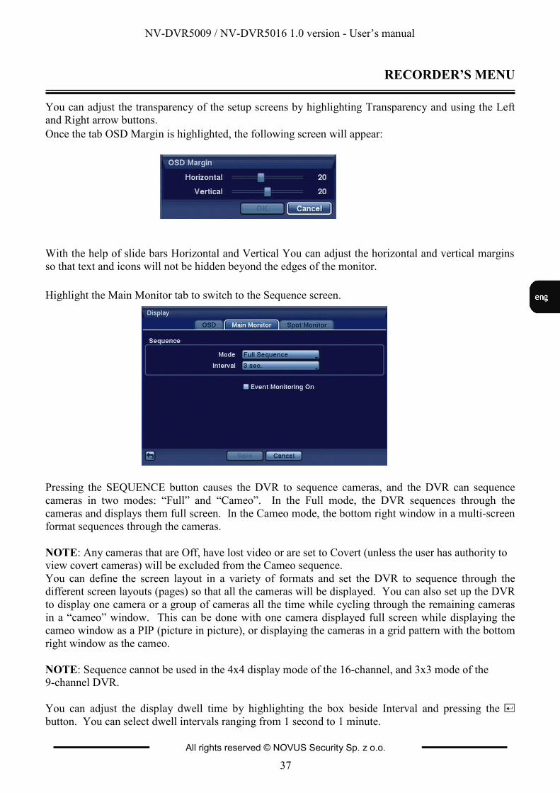
Once the tab OSD Margin is highlighted, the following screen will appear:
With the help of slide bars Horizontal and Vertical You can adjust the horizontal and vertical margins
so that text and icons will not be hidden beyond the edges of the monitor.
Highlight the Main Monitor tab to switch to the Sequence screen.
Pressing the SEQUENCE button causes the DVR to sequence cameras, and the DVR can sequence
cameras in two modes: “Full” and “Cameo”. In the Full mode, the DVR sequences through the
cameras and displays them full screen. In the Cameo mode, the bottom right window in a multi-screen
format sequences through the cameras.
NOTE: Any cameras that are Off, have lost video or are set to Covert (unless the user has authority to view covert cameras) will be excluded from the Cameo sequence.
You can define the screen layout in a variety of formats and set the DVR to sequence through the
different screen layouts (pages) so that all the cameras will be displayed. You can also set up the DVR
to display one camera or a group of cameras all the time while cycling through the remaining cameras
in a “cameo” window. This can be done with one camera displayed full screen while displaying the
cameo window as a PIP (picture in picture), or displaying the cameras in a grid pattern with the bottom
right window as the cameo.
NOTE: Sequence cannot be used in the 4x4 display mode of the 16-channel, and 3x3 mode of the 9-channel DVR.
You can adjust the display dwell time by highlighting the box beside Interval and pressing the
button. You can select dwell intervals ranging from 1 second to 1 minute.
NV-DVR5009 / NV-DVR5016 1.0 version - User’s manual
All rights reserved © NOVUS Security Sp. z o.o.
38
RECORDER’S MENU
Widok dla NV-DVR1600
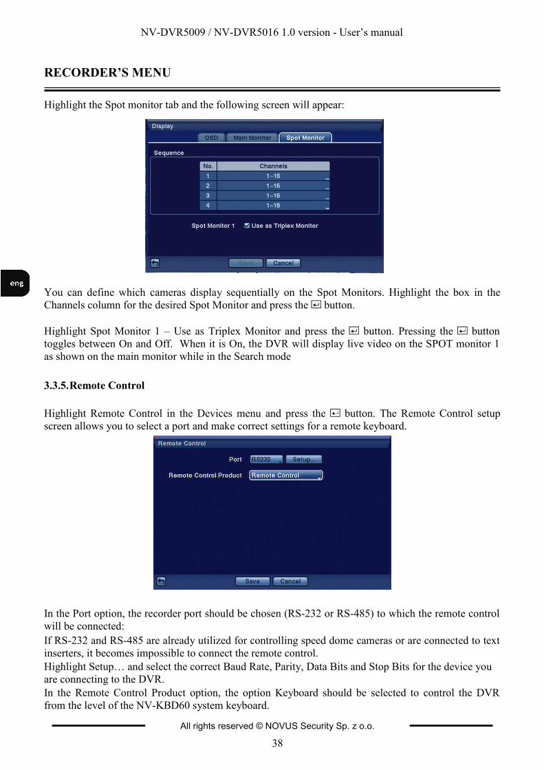
Highlight the Spot monitor tab and the following screen will appear:
You can define which cameras display sequentially on the Spot Monitors. Highlight the box in the
Channels column for the desired Spot Monitor and press the button.
Highlight Spot Monitor 1 – Use as Triplex Monitor and press the button. Pressing the button
toggles between On and Off. When it is On, the DVR will display live video on the SPOT monitor 1
as shown on the main monitor while in the Search mode
3.3.5. Remote Control
Highlight Remote Control in the Devices menu and press the button. The Remote Control setup
screen allows you to select a port and make correct settings for a remote keyboard.
In the Port option, the recorder port should be chosen (RS-232 or RS-485) to which the remote control
will be connected:
If RS-232 and RS-485 are already utilized for controlling speed dome cameras or are connected to text
inserters, it becomes impossible to connect the remote control.
Highlight Setup… and select the correct Baud Rate, Parity, Data Bits and Stop Bits for the device you
are connecting to the DVR.
In the Remote Control Product option, the option Keyboard should be selected to control the DVR
from the level of the NV-KBD60 system keyboard.
NV-DVR5009 / NV-DVR5016 1.0 version - User’s manual
All rights reserved © NOVUS Security Sp. z o.o.
39
RECORDER’S MENU
Widok dla NV-DVR1600
3.4. Recording
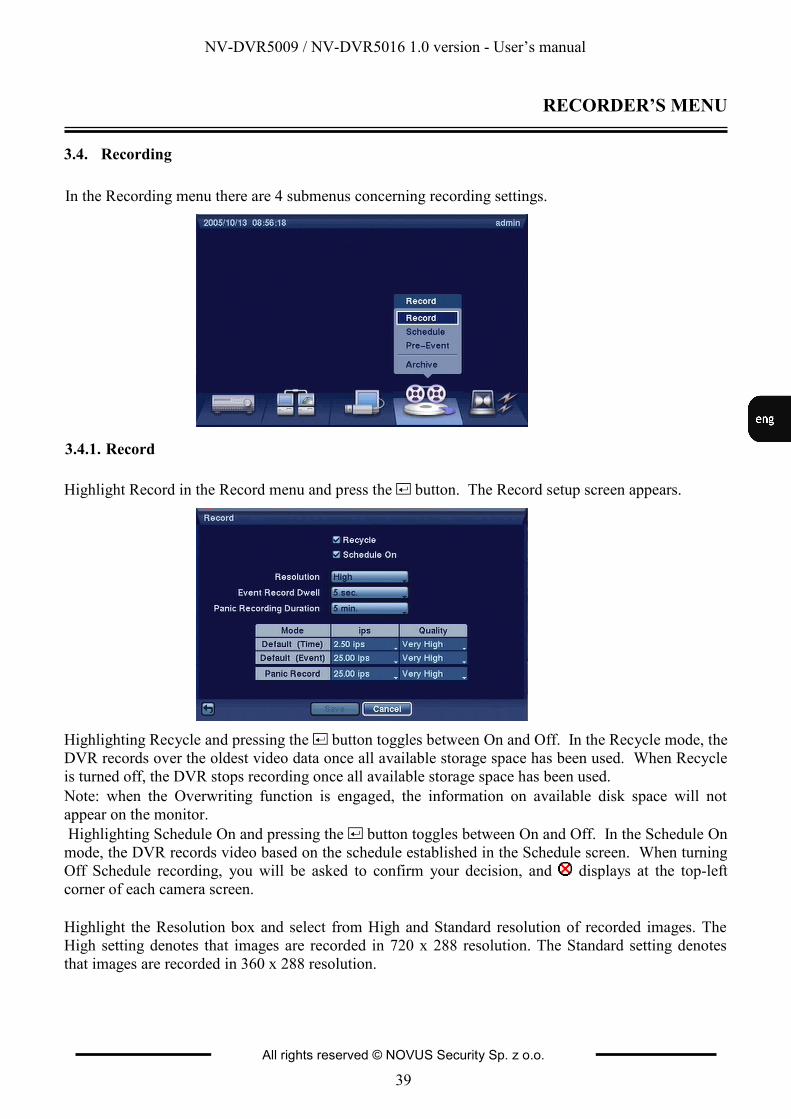
In the Recording menu there are 4 submenus concerning recording settings.
3.4.1. Record
Highlight Record in the Record menu and press the button. The Record setup screen appears.
Highlighting Recycle and pressing the button toggles between On and Off. In the Recycle mode, the
DVR records over the oldest video data once all available storage space has been used. When Recycle
is turned off, the DVR stops recording once all available storage space has been used.
Note: when the Overwriting function is engaged, the information on available disk space will not
appear on the monitor.
Highlighting Schedule On and pressing the button toggles between On and Off. In the Schedule On
mode, the DVR records video based on the schedule established in the Schedule screen. When turning
Off Schedule recording, you will be asked to confirm your decision, and displays at the top-left
corner of each camera screen.
Highlight the Resolution box and select from High and Standard resolution of recorded images. The
High setting denotes that images are recorded in 720 x 288 resolution. The Standard setting denotes
that images are recorded in 360 x 288 resolution.
NV-DVR5009 / NV-DVR5016 1.0 version - User’s manual
All rights reserved © NOVUS Security Sp. z o.o.
40
RECORDER’S MENU
Widok dla NV-DVR1600
Resolution settings are defined globally for the complete system.
NOTE: Recording speed decreases by half when resolution is increased from standard 360 x 288 to 720 x 288 .
Highlight the Event Record Dwell box and set the length of time you would like to record for the
associated event. You can set the dwell from 5 seconds to 15 minutes. Refer to Event Actions screen
in this chapter for the information of event recording.
Highlight the Panic Recording Duration box and set the duration of panic recording. The panic
recording will be stopped automatically according to the preset duration as long as the PANIC button is
not pressed to stop the panic recording. You can set the dwell from 5 minutes to 1 hour. Select No
Limit if you want to stop panic recording manually.
NOTE: Activating hold-up recording is only possible when the user is logged-in to the device.
Highlighting boxes under Ips and pressing the button allows you to set the images per second for
Time, Event and Panic recording. You can select from 0.10 to 25.0 images per second.
NV-DVR5009 / NV-DVR5016 1.0 version - User’s manual
All rights reserved © NOVUS Security Sp. z o.o.
41
RECORDER’S MENU
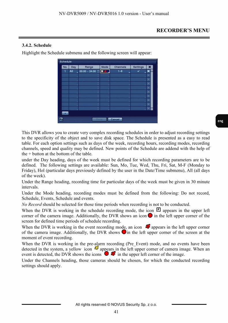
3.4.2. Schedule
Highlight the Schedule submenu and the following screen will appear:
This DVR allows you to create very complex recording schedules in order to adjust recording settings
to the specificity of the object and to save disk space. The Schedule is presented as a easy to read
table. For each option settings such as days of the week, recording hours, recording modes, recording
channels, speed and quality may be defined. New points of the Schedule are addend with the help of
the + button at the bottom of the table.
under the Day heading, days of the week must be defined for which recording parameters are to be
defined. The following settings are available: Sun, Mo, Tue, Wed, Thu, Fri, Sat, M-F (Monday to
Friday), Hol (particular days previously defined by the user in the Date/Time submenu), All (all days
of the week).
Under the Range heading, recording time for particular days of the week must be given in 30 minute
intervals.
Under the Mode heading, recording modes must be defined from the following: Do not record,
Schedule, Events, Schedule and events.
No Record should be selected for those time periods when recording is not to be conducted.
When the DVR is working in the schedule recording mode, the icon appears in the upper left
corner of the camera image. Additionally, the DVR shows an icon in the left upper corner of the
screen for defined time periods of schedule recording.
When the DVR is working in the event recording mode, an icon appears in the left upper corner
of the camera image. Additionally, the DVR shows in the left upper corner of the screen at the
moment of event recording.
When the DVR is working in the pre-alarm recording (Pre_Event) mode, and no events have been
detected in the system, a yellow icon appears in the left upper corner of camera image. When an
event is detected, the DVR shows the icons in the upper left corner of the image.
Under the Channels heading, those cameras should be chosen, for which the conducted recording
settings should apply.
NV-DVR5009 / NV-DVR5016 1.0 version - User’s manual
All rights reserved © NOVUS Security Sp. z o.o.
42
RECORDER’S MENU
Widok dla NV-DVR1600
Under the Settings heading, recording speed should be defined in the range between 0.1 to 25 frames
per second, as well as recording quality: Highest, High, Standard and Low. By choosing the X option,
a selected point of the Schedule may be erased.
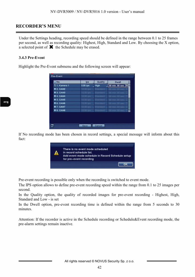
3.4.3 Pre-Event
Highlight the Pre-Event submenu and the following screen will appear:
If No recording mode has been chosen in record settings, a special message will inform about this
fact:
Pre-event recording is possible only when the recording is switched to event mode.
The IPS option allows to define pre-event recording speed within the range from 0.1 to 25 images per
second.
In the Quality option, the quality of recorded images for pre-event recording - Highest, High,
Standard and Low - is set
In the Dwell option, pre-event recording time is defined within the range from 5 seconds to 30
minutes.
Attention: If the recorder is active in the Schedule recording or Schedule&Event recording mode, the
pre-alarm settings remain inactive.
NV-DVR5009 / NV-DVR5016 1.0 version - User’s manual
All rights reserved © NOVUS Security Sp. z o.o.
43
RECORDER’S MENU
Widok dla NV-DVR1600
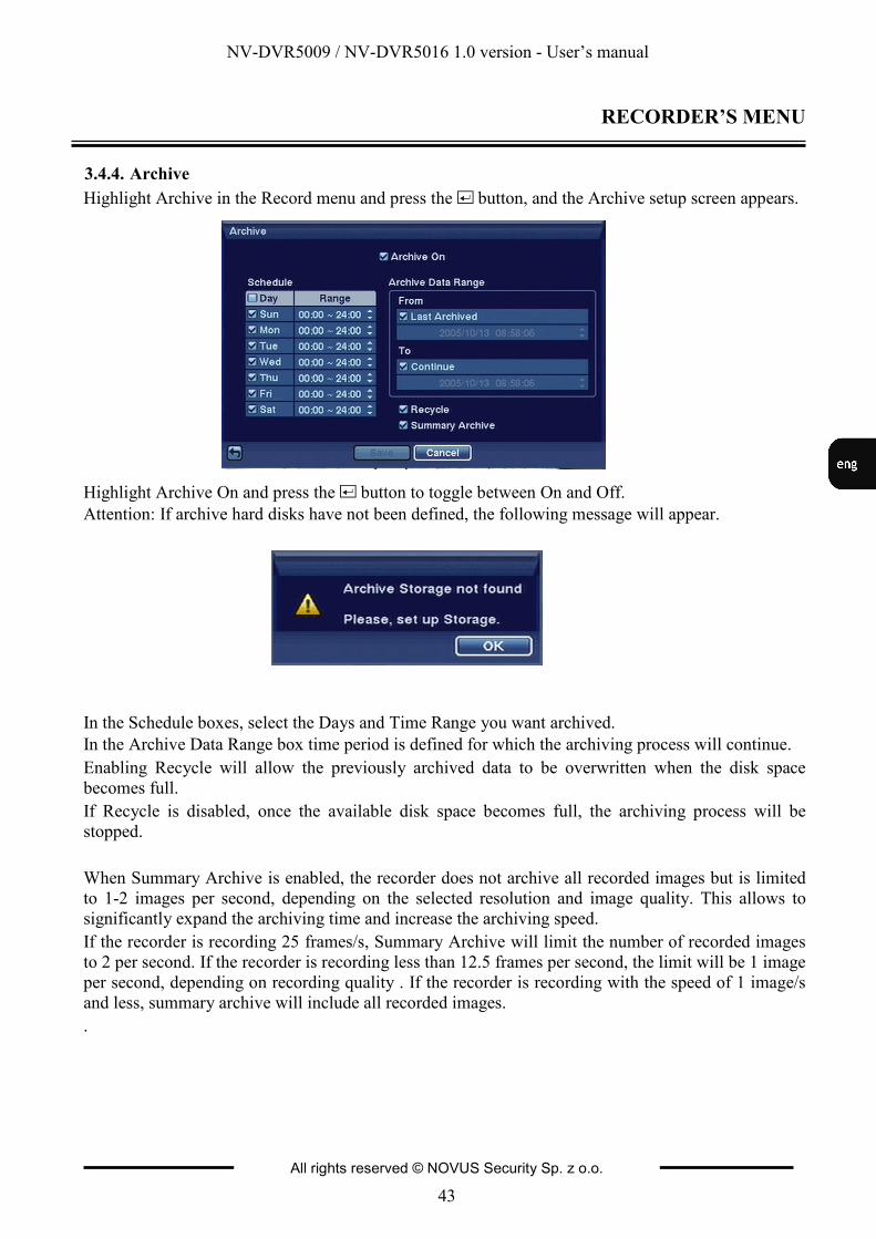
3.4.4. Archive
Highlight Archive in the Record menu and press the button, and the Archive setup screen appears.
Highlight Archive On and press the button to toggle between On and Off.
Attention: If archive hard disks have not been defined, the following message will appear.
In the Schedule boxes, select the Days and Time Range you want archived.
In the Archive Data Range box time period is defined for which the archiving process will continue.
Enabling Recycle will allow the previously archived data to be overwritten when the disk space
becomes full.
If Recycle is disabled, once the available disk space becomes full, the archiving process will be
stopped.
When Summary Archive is enabled, the recorder does not archive all recorded images but is limited
to 1-2 images per second, depending on the selected resolution and image quality. This allows to
significantly expand the archiving time and increase the archiving speed.
If the recorder is recording 25 frames/s, Summary Archive will limit the number of recorded images
to 2 per second. If the recorder is recording less than 12.5 frames per second, the limit will be 1 image
per second, depending on recording quality . If the recorder is recording with the speed of 1 image/s
and less, summary archive will include all recorded images.
.
NV-DVR5009 / NV-DVR5016 1.0 version - User’s manual
All rights reserved © NOVUS Security Sp. z o.o.
44
RECORDER’S MENU
Widok dla NV-DVR1600
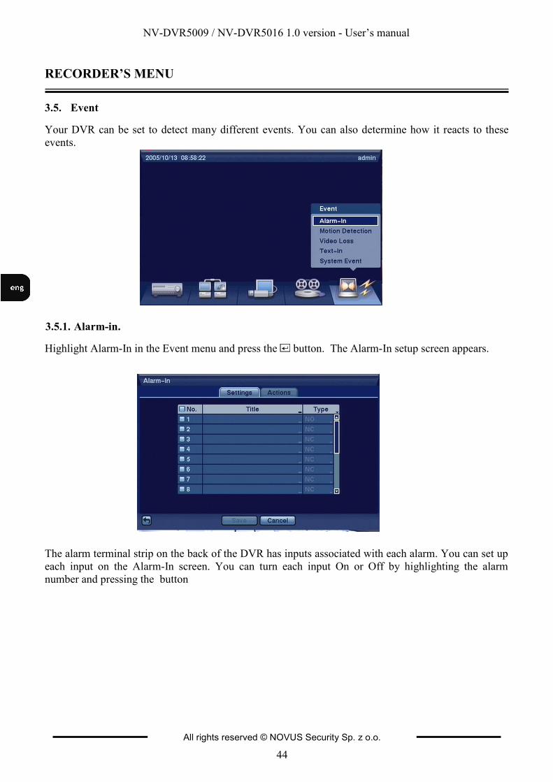
3.5. Event
Your DVR can be set to detect many different events. You can also determine how it reacts to these
events.
3.5.1. Alarm-in.
Highlight Alarm-In in the Event menu and press the button. The Alarm-In setup screen appears.
The alarm terminal strip on the back of the DVR has inputs associated with each alarm. You can set up
each input on the Alarm-In screen. You can turn each input On or Off by highlighting the alarm
number and pressing the button
NV-DVR5009 / NV-DVR5016 1.0 version - User’s manual
All rights reserved © NOVUS Security Sp. z o.o.
45
RECORDER’S MENU
Widok dla NV-DVR1600
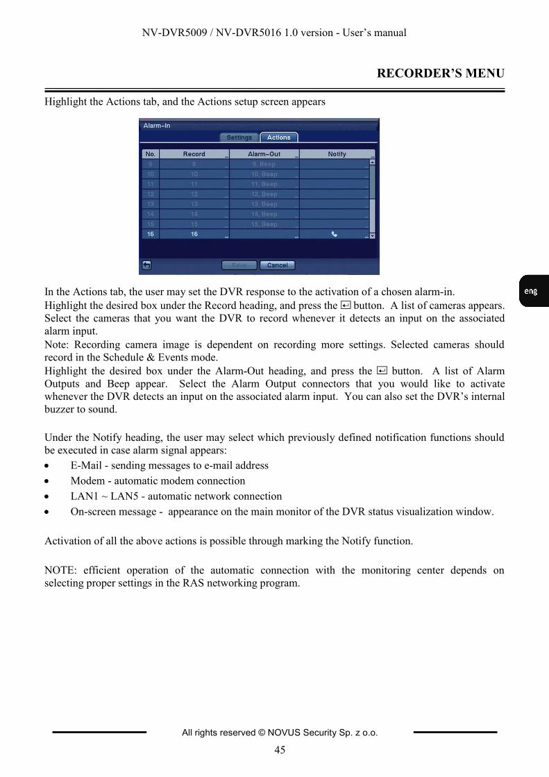
Highlight the Actions tab, and the Actions setup screen appears
In the Actions tab, the user may set the DVR response to the activation of a chosen alarm-in.
Highlight the desired box under the Record heading, and press the button. A list of cameras appears.
Select the cameras that you want the DVR to record whenever it detects an input on the associated
alarm input.
Note: Recording camera image is dependent on recording more settings. Selected cameras should
record in the Schedule & Events mode.
Highlight the desired box under the Alarm-Out heading, and press the button. A list of Alarm
Outputs and Beep appear. Select the Alarm Output connectors that you would like to activate
whenever the DVR detects an input on the associated alarm input. You can also set the DVR’s internal
buzzer to sound.
Under the Notify heading, the user may select which previously defined notification functions should
be executed in case alarm signal appears:
• E-Mail - sending messages to e-mail address
• Modem - automatic modem connection
• LAN1 ~ LAN5 - automatic network connection
• On-screen message - appearance on the main monitor of the DVR status visualization window.
Activation of all the above actions is possible through marking the Notify function.
NOTE: efficient operation of the automatic connection with the monitoring center depends on
selecting proper settings in the RAS networking program.
NV-DVR5009 / NV-DVR5016 1.0 version - User’s manual
All rights reserved © NOVUS Security Sp. z o.o.
46
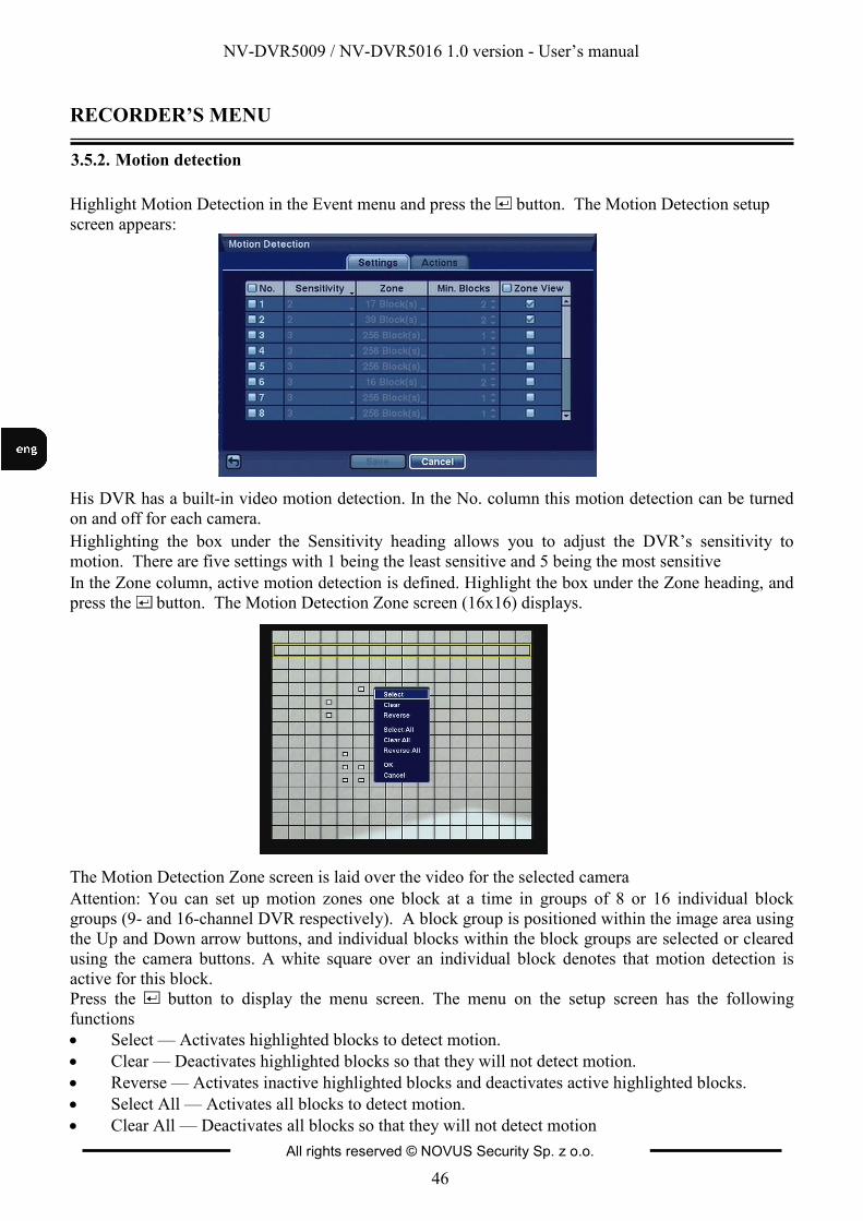
RECORDER’S MENU
3.5.2. Motion detection
Highlight Motion Detection in the Event menu and press the button. The Motion Detection setup
screen appears:
His DVR has a built-in video motion detection. In the No. column this motion detection can be turned
on and off for each camera.
Highlighting the box under the Sensitivity heading allows you to adjust the DVR’s sensitivity to
motion. There are five settings with 1 being the least sensitive and 5 being the most sensitive
In the Zone column, active motion detection is defined. Highlight the box under the Zone heading, and
press the button. The Motion Detection Zone screen (16x16) displays.
The Motion Detection Zone screen is laid over the video for the selected camera
Attention: You can set up motion zones one block at a time in groups of 8 or 16 individual block
groups (9- and 16-channel DVR respectively). A block group is positioned within the image area using
the Up and Down arrow buttons, and individual blocks within the block groups are selected or cleared
using the camera buttons. A white square over an individual block denotes that motion detection is
active for this block.
Press the button to display the menu screen. The menu on the setup screen has the following
functions
• Select — Activates highlighted blocks to detect motion.
• Clear — Deactivates highlighted blocks so that they will not detect motion.
• Reverse — Activates inactive highlighted blocks and deactivates active highlighted blocks.
• Select All — Activates all blocks to detect motion.
• Clear All — Deactivates all blocks so that they will not detect motion
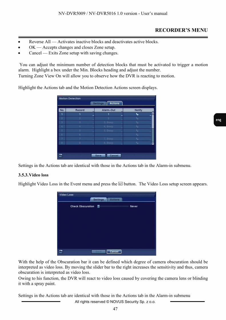
NV-DVR5009 / NV-DVR5016 1.0 version - User’s manual
All rights reserved © NOVUS Security Sp. z o.o.
47
RECORDER’S MENU
Widok dla NV-DVR1600
• Reverse All — Activates inactive blocks and deactivates active blocks.
• OK — Accepts changes and closes Zone setup.
• Cancel — Exits Zone setup with saving changes.
You can adjust the minimum number of detection blocks that must be activated to trigger a motion
alarm. Highlight a box under the Min. Blocks heading and adjust the number.
Turning Zone View On will allow you to observe how the DVR is reacting to motion.
Highlight the Actions tab and the Motion Detection Actions screen displays.
Settings in the Actions tab are identical with those in the Actions tab in the Alarm-in submenu.
3.5.3. Video loss
Highlight Video Loss in the Event menu and press the button. The Video Loss setup screen appears.
With the help of the Obscuration bar it can be defined which degree of camera obscuration should be
interpreted as video loss. By moving the slider bar to the right increases the sensitivity and thus, camera
obscuration is interpreted as video loss.
Owing to his function, the DVR will react to video loss caused by covering the camera lens or blinding
it with a spray paint.
Settings in the Actions tab are identical with those in the Actions tab in the Alarm-in submenu
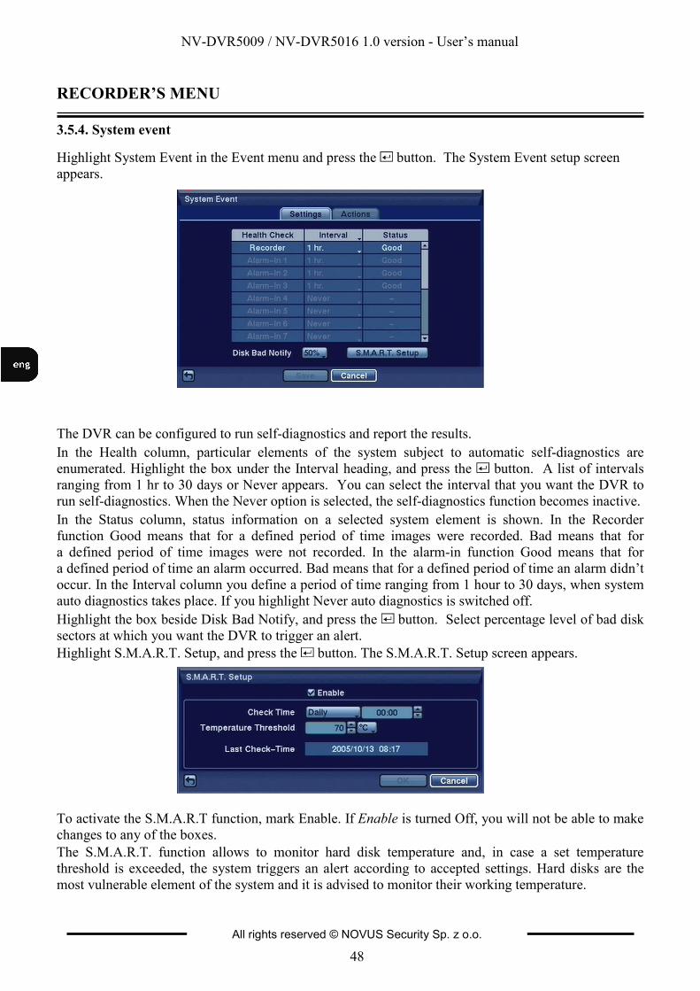
NV-DVR5009 / NV-DVR5016 1.0 version - User’s manual
All rights reserved © NOVUS Security Sp. z o.o.
48
RECORDER’S MENU
Widok dla NV-DVR1600
3.5.4. System event
Highlight System Event in the Event menu and press the button. The System Event setup screen
appears.
The DVR can be configured to run self-diagnostics and report the results.
In the Health column, particular elements of the system subject to automatic self-diagnostics are
enumerated. Highlight the box under the Interval heading, and press the button. A list of intervals
ranging from 1 hr to 30 days or Never appears. You can select the interval that you want the DVR to
run self-diagnostics. When the Never option is selected, the self-diagnostics function becomes inactive.
In the Status column, status information on a selected system element is shown. In the Recorder
function Good means that for a defined period of time images were recorded. Bad means that for
a defined period of time images were not recorded. In the alarm-in function Good means that for
a defined period of time an alarm occurred. Bad means that for a defined period of time an alarm didn’t
occur. In the Interval column you define a period of time ranging from 1 hour to 30 days, when system
auto diagnostics takes place. If you highlight Never auto diagnostics is switched off.
Highlight the box beside Disk Bad Notify, and press the button. Select percentage level of bad disk
sectors at which you want the DVR to trigger an alert.
Highlight S.M.A.R.T. Setup, and press the button. The S.M.A.R.T. Setup screen appears.
To activate the S.M.A.R.T function, mark Enable. If Enable is turned Off, you will not be able to make
changes to any of the boxes.
The S.M.A.R.T. function allows to monitor hard disk temperature and, in case a set temperature
threshold is exceeded, the system triggers an alert according to accepted settings. Hard disks are the
most vulnerable element of the system and it is advised to monitor their working temperature.
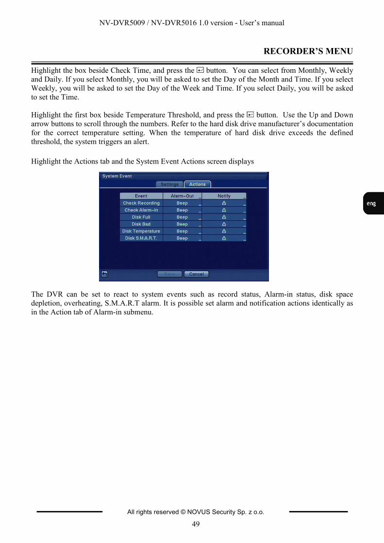
NV-DVR5009 / NV-DVR5016 1.0 version - User’s manual
All rights reserved © NOVUS Security Sp. z o.o.
49
RECORDER’S MENU
Highlight the box beside Check Time, and press the button. You can select from Monthly, Weekly
and Daily. If you select Monthly, you will be asked to set the Day of the Month and Time. If you select
Weekly, you will be asked to set the Day of the Week and Time. If you select Daily, you will be asked
to set the Time.
Highlight the first box beside Temperature Threshold, and press the button. Use the Up and Down
arrow buttons to scroll through the numbers. Refer to the hard disk drive manufacturer’s documentation
for the correct temperature setting. When the temperature of hard disk drive exceeds the defined
threshold, the system triggers an alert.
Highlight the Actions tab and the System Event Actions screen displays
The DVR can be set to react to system events such as record status, Alarm-in status, disk space
depletion, overheating, S.M.A.R.T alarm. It is possible set alarm and notification actions identically as
in the Action tab of Alarm-in submenu.
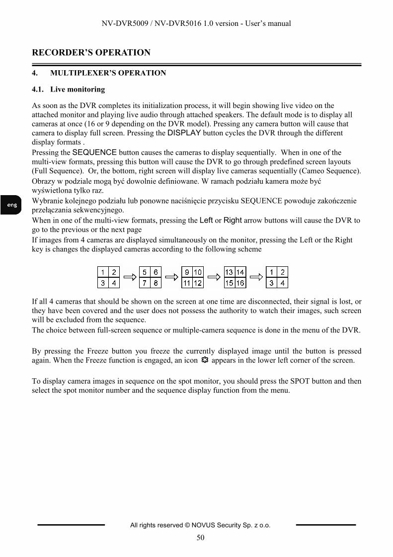
NV-DVR5009 / NV-DVR5016 1.0 version - User’s manual
All rights reserved © NOVUS Security Sp. z o.o.
50
RECORDER’S OPERATION
Widok dla NV-DVR1600
4. MULTIPLEXER’S OPERATION
4.1. Live monitoring
As soon as the DVR completes its initialization process, it will begin showing live video on the
attached monitor and playing live audio through attached speakers. The default mode is to display all
cameras at once (16 or 9 depending on the DVR model). Pressing any camera button will cause that
camera to display full screen. Pressing the DISPLAY button cycles the DVR through the different display formats .
Pressing the SEQUENCE button causes the cameras to display sequentially. When in one of the
multi-view formats, pressing this button will cause the DVR to go through predefined screen layouts
(Full Sequence). Or, the bottom, right screen will display live cameras sequentially (Cameo Sequence).
Obrazy w podziale mogą być dowolnie definiowane. W ramach podziału kamera może być
wyświetlona tylko raz.
Wybranie kolejnego podziału lub ponowne naciśnięcie przycisku SEQUENCE powoduje zakończenie
przełączania sekwencyjnego.
When in one of the multi-view formats, pressing the Left or Right arrow buttons will cause the DVR to go to the previous or the next page
If images from 4 cameras are displayed simultaneously on the monitor, pressing the Left or the Right
key is changes the displayed cameras according to the following scheme
If all 4 cameras that should be shown on the screen at one time are disconnected, their signal is lost, or
they have been covered and the user does not possess the authority to watch their images, such screen
will be excluded from the sequence.
The choice between full-screen sequence or multiple-camera sequence is done in the menu of the DVR.
By pressing the Freeze button you freeze the currently displayed image until the button is pressed
again. When the Freeze function is engaged, an icon appears in the lower left corner of the screen.
To display camera images in sequence on the spot monitor, you should press the SPOT button and then
select the spot monitor number and the sequence display function from the menu.
NV-DVR5009 / NV-DVR5016 1.0 version - User’s manual
All rights reserved © NOVUS Security Sp. z o.o.
51
RECORDER’S OPERATION
Widok dla NV-DVR1600
4.2. Active Cameo Mode
You can enter the Active Cameo mode by pressing the button in any multi-view format. The yellow
outline surrounding the video indicates the active cameo, and pressing the arrow buttons moves the
active cameo. Pressing the button while in the Active Cameo mode exits the Active Cameo mode.
The active cameo mode will remains in effect for 15 seconds if there is no further operation.
In active cameo mode, press the numeric button for the camera you want displayed as active cameo
(with the yellow outline). After setting the camera number to active cameo, the DVR moves the active
cameo to the next cameo. You can change the screen layout in this way.
Attention: Particular cameras may be shown only once within a single screen, that is picture from
a particular camera may not be shown more than once on the screen of one user.
4.3. PIP Mode
You can display a Picture-in-Picture by pressing the DISPLAY button. You can change the location of
the PIP counterclockwise and clockwise by pressing the Up and Down arrow buttons and change its
size by turning the Jog Dial clockwise or counterclockwise.
4.4. Zoom Mode
You can enlarge an area of the video by pressing the ZOOM button. For a few seconds after pressing
the ZOOM button, a PIP displays. Inside the PIP, a rectangle shows the area that is enlarged. You can
move the rectangle around using the arrow buttons. While in the Zoom mode, you can enlarge the area
more by pressing the button. The Zoom mode options are 2x, 3x and 4x. Exit the Zoom mode by
pressing the ZOOM button. While in the Zoom mode, the icon displays in bottom-left corner if
Zoom is selected in the Display setup screen (OSD tab).
4.5. PTZ Mode
If a user who has PTZ Control authority logs into the system, the user can control PTZ cameras. The
DVR will control cameras with Pan, Tilt and Zoom capabilities. Press the PTZ button to enter the PTZ
mode and press the button again to exit the PTZ mode. You can control the camera using front panel
control buttons, by setting up presets or by selecting the expanded PTZ features.
Once the PTZ buton is pressed, cameras defined as PTZ will be shown on the screen PTZ. Select the
PTZ camera you wish to control from the menu with the help of Up and Down arrow buttons. The icon
displays on the PTZ camera screen.
Use the front panel buttons, press the Left and Right arrow buttons to pan left and right. Press the Up
and Down arrow buttons to tilt the camera up and down. Press the button to zoom in, and press the
button to zoom out. You can use the and buttons to focus the image.

NV-DVR5009 / NV-DVR5016 1.0 version - User’s manual
All rights reserved © NOVUS Security Sp. z o.o.
52
RECORDER’S OPERATION
Widok dla NV-DVR1600
To program a preset, direct the camera at a selected scene and press Enter.
When the PTZ dialog box appears, select the number you want to assign to the preset and press the
button. Use the virtual keyboard to enter the preset name. Press the button to load the PTZ preset
and the Preset View dialog box will appear. Select the desired preset and press the button to load the
preset.
Pressing the MENU button displays the PTZ menu. Set the feature you wish to control by selecting it
from the menu. Refer to the camera manufacturer’s instructions for the proper settings. Depending on
the camera specifications, some features may not be supported.
You can use a USB mouse for convenient PTZ control. Position the mouse point at the bottom of the
screen, and the following PTZ toolbar will display.
Clicking on the left side exits the toolbar. If you want to display the toolbar again, position the mouse
pointer at the bottom of the screen. Change the toolbar location by clicking the empty space on the left
side of the toolbar and drag it to where you want it located on the screen.
4.6. Image adjustment
It is important that cameras and monitors are correctly installed and adjusted (sharpness, white balance)
prior to making any image adjustments using the DVR’s controls.
If a user who has Color Control authority logs into the system, the user can adjust the image. Pressing
and holding a camera button for a few seconds displays an image adjustment dialog. You can control
the following settings for each camera:
• brightness,
• contrast,
• hue,
• saturation.
NOTE: Any image adjustments you make will be applied to both life image on the monitors and to
recorded video
NV-DVR5009 / NV-DVR5016 1.0 version - User’s manual
All rights reserved © NOVUS Security Sp. z o.o.
53
RECORDER’S OPERATION
Widok dla NV-DVR1600
4.7. Event monitoring
When an event occurs, the DVR will display the camera associated with the event if Event Monitoring
On is selected in the Display setup screen (OSD tab).
How the cameras are displayed depends on the number of cameras associated with the event and on the
number of events that are taking place simultaneously.
If one camera is associated with the event, the DVR will display the camera full screen. If two to four
cameras are associated with the event, the DVR will display the cameras on a 2x2 screen. If five to nine
cameras are associated with the event, the DVR will display the cameras on a 3x3 screen. If 10 or more
cameras are associated with the event, the DVR will display the cameras on a 4x4 screen.
Event monitoring lasts for the dwell time set for event recording. After the dwell time has elapsed, the
monitor returns to the previous screen unless another event has occurred. If you want to return to the
live monitoring mode before the dwell time has elapsed, press the DISPLAY button or one of the
camera buttons.
4.8. Covert cameras
If a camera is set up as Covert 1 in the Camera setup screen (Settings tab), that camera will not be
displayed unless a user with Covert Camera View authority logs into the system. However the camera
title and status icons will be displayed on the monitor.
If a camera is set up as Covert 2 in the Camera setup screen (Settings tab), that camera appears to be
Off unless a user with Covert Camera View authority logs into the system. The camera title will be
grayed out and status icons will not be displayed on the monitor.
4.9. Spot monitors
You can select the camera you want to display on a Spot Monitor. Press the SPOT button on the front
panel or remote control, and select one of four Spot Monitors. Then, select the camera to be displayed
on the Spot Monitor.
If you want to display more than one camera on a Spot Monitor, you can display them sequentially. In
the Spot Monitor selection mode, press the SEQUENCE button on the front panel or remote control, or
select Sequence On from the menu to start displaying cameras sequentially. Any cameras that are Off,
have lost video or are set to Covert (unless the user has authority to view covert cameras) will be
excluded from the sequence. Sequence dwell time is defined in the DVR menu.
4.10. Using a Mouse
You can use a USB mouse instead of the front panel buttons to perform many of the DVR functions.
The following operations are supported when using a mouse during live monitoring.
When in one of the multi-view formats (e.g., PIP, 2x2, 3x3 or 4x4), clicking the mouse button on a
camera image switches that camera to full screen. Clicking the mouse button again returns to the
previous multi-view format.
Scrolling the mouse wheel alternates screen mode (switching from PIP to 2x2 to 3x3 to 4x4), just like
pressing the DISPLAY button on the front panel of the DVR.
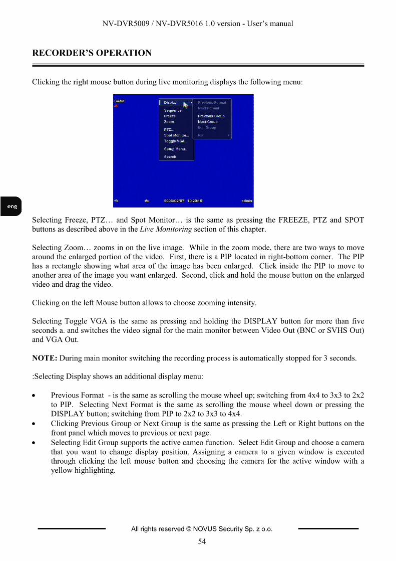
NV-DVR5009 / NV-DVR5016 1.0 version - User’s manual
All rights reserved © NOVUS Security Sp. z o.o.
54
RECORDER’S OPERATION
Clicking the right mouse button during live monitoring displays the following menu:
Selecting Freeze, PTZ… and Spot Monitor… is the same as pressing the FREEZE, PTZ and SPOT
buttons as described above in the Live Monitoring section of this chapter.
Selecting Zoom… zooms in on the live image. While in the zoom mode, there are two ways to move
around the enlarged portion of the video. First, there is a PIP located in right-bottom corner. The PIP
has a rectangle showing what area of the image has been enlarged. Click inside the PIP to move to
another area of the image you want enlarged. Second, click and hold the mouse button on the enlarged
video and drag the video.
Clicking on the left Mouse button allows to choose zooming intensity.
Selecting Toggle VGA is the same as pressing and holding the DISPLAY button for more than five
seconds a. and switches the video signal for the main monitor between Video Out (BNC or SVHS Out)
and VGA Out.
NOTE: During main monitor switching the recording process is automatically stopped for 3 seconds.
:Selecting Display shows an additional display menu:
• Previous Format - is the same as scrolling the mouse wheel up; switching from 4x4 to 3x3 to 2x2
to PIP. Selecting Next Format is the same as scrolling the mouse wheel down or pressing the
DISPLAY button; switching from PIP to 2x2 to 3x3 to 4x4.
• Clicking Previous Group or Next Group is the same as pressing the Left or Right buttons on the
front panel which moves to previous or next page.
• Selecting Edit Group supports the active cameo function. Select Edit Group and choose a camera
that you want to change display position. Assigning a camera to a given window is executed
through clicking the left mouse button and choosing the camera for the active window with a
yellow highlighting.
NV-DVR5009 / NV-DVR5016 1.0 version - User’s manual
All rights reserved © NOVUS Security Sp. z o.o.
55
RECORDER’S OPERATION
Widok dla NV-DVR1600
4.11. Recording video
Maximum recording speed of images in 360 x 288 resolution (PAL) is 200 images / s. for the complete
system.
Maximum recording speed of images in 720 x 288 resolution (PAL) is 100 images / s. for the complete
system.
NOTE: When the DVR is in the search mode, the maximum recording speed decreases by half. For the standard resolution of 360 x 288 (PAL) recording speed drops to 100 images/s, whereas for the high
resolution of 720 x 288 (PAL) it decreases to 50 images/s.
NOTE: If the DVR is not working in the recycle mode and available disk space becomes exhausted, hold-up recording is not executed.
4.12. Recording audio
If the DVR was set up to record audio, it will record audio from up to four inputs when video is
recording. The DVR will not record audio when the recording speed is set to less than 1 ips.
NOTE: Make certain you comply with all applicable laws and regulations when recording audio.
4.13. Playing recorded video
If a user who has Search authority logs into the system, the user can view recorded image. Once video
has been recorded, you can view it by pressing the PLAY/PAUSE button. When playing video for the
first time, the DVR will display the most recent image. When playing video subsequent times, the
DVR will start playing video from the last recalled image.
NOTE: Only the administrator and users with Covert Camera View authority can view video from covert cameras. The covert cameras in the playback mode are determined by the current camera
setting.
Pressing the PLAY/PAUSE button again will freeze the video on the screen (pause)
RW (REWIND) - Pressing the RW button plays video backward at high speed. Pressing the button again toggles the playback speed between , and . The screen displays , and
respectively.
FF (FAST FORWARD) - Pressing the FF button plays video forward at high speed. Pressing the button again toggles the playback speed between , and . The screen displays , and
respectively.
FORWARD - Pressing the FORWARD button goes to the next image.
BACKWARD - Pressing the BACKWARD button goes to the previous image.
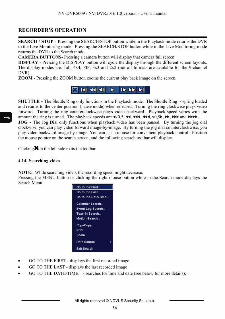
NV-DVR5009 / NV-DVR5016 1.0 version - User’s manual
All rights reserved © NOVUS Security Sp. z o.o.
56
RECORDER’S OPERATION
SEARCH / STOP - Pressing the SEARCH/STOP button while in the Playback mode returns the DVR to the Live Monitoring mode. Pressing the SEARCH/STOP button while in the Live Monitoring mode
returns the DVR to the Search mode.
CAMERA BUTTONS- Pressing a camera button will display that camera full screen.
DISPLAY - Pressing the DISPLAY button will cycle the display through the different screen layouts. The display modes are: full, 4x4, PIP, 3x3 and 2x2 (not all formats are available for the 9-channel
DVR).
ZOOM - Pressing the ZOOM button zooms the current play back image on the screen.
SHUTTLE - The Shuttle Ring only functions in the Playback mode. The Shuttle Ring is spring loaded and returns to the center position (pause mode) when released. Turning the ring clockwise plays video
forward. Turning the ring counterclockwise plays video backward. Playback speed varies with the
amount the ring is turned. The playback speeds are x0,5, , , , x0,5 , , and .
JOG - The Jog Dial only functions when playback video has been paused. By turning the jog dial clockwise, you can play video forward image-by-image. By turning the jog dial counterclockwise, you
play video backward image-by-image. You can use a mouse for convenient playback control. Position
the mouse pointer on the search screen, and the following search toolbar will display.
Clicking on the left side exits the toolbar
4.14. Searching video
NOTE: While searching video, the recording speed might decrease. Pressing the MENU button or clicking the right mouse button while in the Search mode displays the
Search Menu.
• GO TO THE FIRST - displays the first recorded image
• GO TO THE LAST - displays the last recorded image
• GO TO THE DATE/TIME... - searches for time and date (see below for more details);
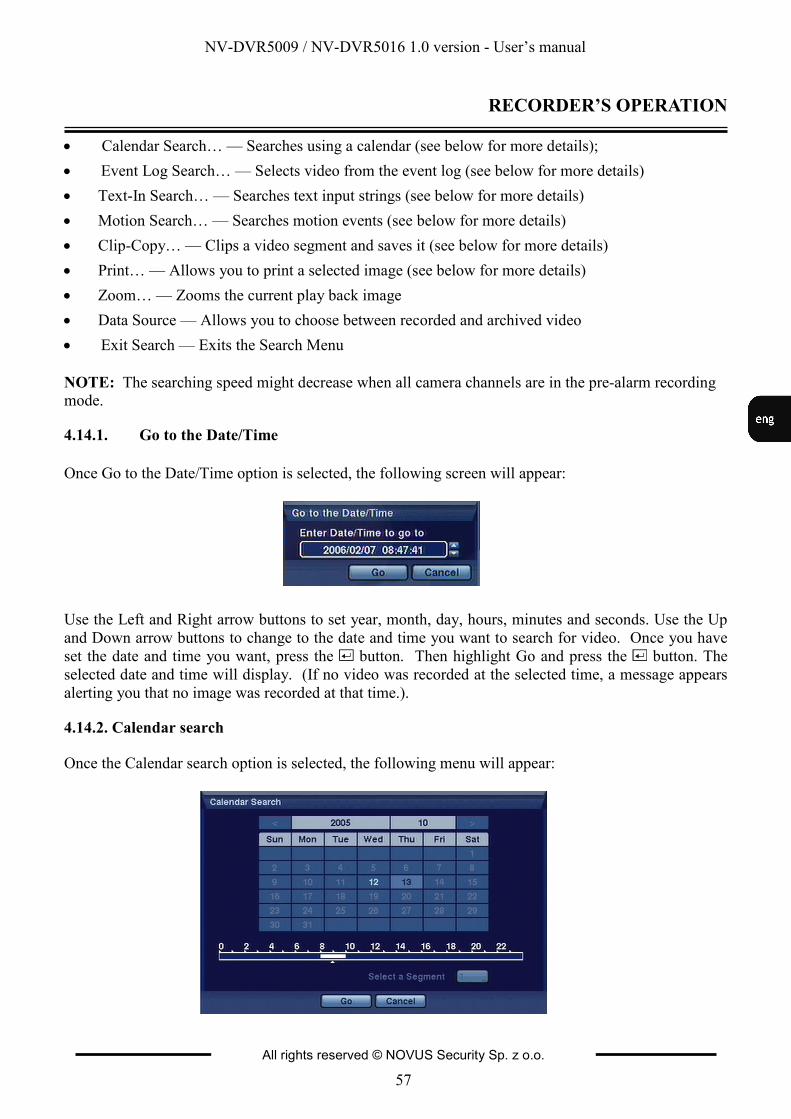
NV-DVR5009 / NV-DVR5016 1.0 version - User’s manual
All rights reserved © NOVUS Security Sp. z o.o.
57
RECORDER’S OPERATION
• Calendar Search… — Searches using a calendar (see below for more details);
• Event Log Search… — Selects video from the event log (see below for more details)
• Text-In Search… — Searches text input strings (see below for more details)
• Motion Search… — Searches motion events (see below for more details)
• Clip-Copy… — Clips a video segment and saves it (see below for more details)
• Print… — Allows you to print a selected image (see below for more details)
• Zoom… — Zooms the current play back image
• Data Source — Allows you to choose between recorded and archived video
• Exit Search — Exits the Search Menu
NOTE: The searching speed might decrease when all camera channels are in the pre-alarm recording mode.
4.14.1. Go to the Date/Time
Once Go to the Date/Time option is selected, the following screen will appear:
Use the Left and Right arrow buttons to set year, month, day, hours, minutes and seconds. Use the Up
and Down arrow buttons to change to the date and time you want to search for video. Once you have
set the date and time you want, press the button. Then highlight Go and press the button. The
selected date and time will display. (If no video was recorded at the selected time, a message appears
alerting you that no image was recorded at that time.).
4.14.2. Calendar search
Once the Calendar search option is selected, the following menu will appear:
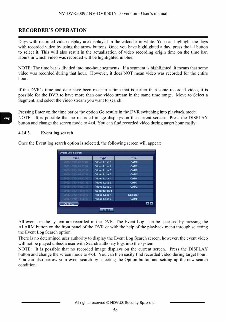
NV-DVR5009 / NV-DVR5016 1.0 version - User’s manual
All rights reserved © NOVUS Security Sp. z o.o.
58
RECORDER’S OPERATION
Days with recorded video display are displayed in the calendar in white. You can highlight the days
with recorded video by using the arrow buttons. Once you have highlighted a day, press the button
to select it. This will also result in the actualization of video recording origin time on the time bar.
Hours in which video was recorded will be highlighted in blue.
NOTE: The time bar is divided into one-hour segments. If a segment is highlighted, it means that some
video was recorded during that hour. However, it does NOT mean video was recorded for the entire
hour.
If the DVR’s time and date have been reset to a time that is earlier than some recorded video, it is
possible for the DVR to have more than one video stream in the same time range. Move to Select a
Segment, and select the video stream you want to search.
Pressing Enter on the time bar or the option Go results in the DVR switching into playback mode.
NOTE: It is possible that no recorded image displays on the current screen. Press the DISPLAY
button and change the screen mode to 4x4. You can find recorded video during target hour easily.
4.14.3. Event log search
Once the Event log search option is selected, the following screen will appear:
All events in the system are recorded in the DVR. The Event Log can be accessed by pressing the
ALARM button on the front panel of the DVR or with the help of the playback menu through selecting
the Event Log Search option.
There is no determined user authority to display the Event Log Search screen, however, the event video
will not be played unless a user with Search authority logs into the system.
NOTE: It is possible that no recorded image displays on the current screen. Press the DISPLAY
button and change the screen mode to 4x4. You can then easily find recorded video during target hour.
You can also narrow your event search by selecting the Option button and setting up the new search
condition.
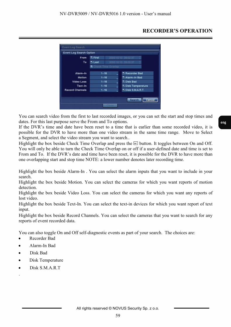
NV-DVR5009 / NV-DVR5016 1.0 version - User’s manual
All rights reserved © NOVUS Security Sp. z o.o.
59
RECORDER’S OPERATION
You can search video from the first to last recorded images, or you can set the start and stop times and
dates. For this last purpose serve the From and To options.
If the DVR’s time and date have been reset to a time that is earlier than some recorded video, it is
possible for the DVR to have more than one video stream in the same time range. Move to Select
a Segment, and select the video stream you want to search..
Highlight the box beside Check Time Overlap and press the button. It toggles between On and Off.
You will only be able to turn the Check Time Overlap on or off if a user-defined date and time is set to
From and To. If the DVR’s date and time have been reset, it is possible for the DVR to have more than
one overlapping start and stop time NOTE: a lower number denotes later recording time.
Highlight the box beside Alarm-In . You can select the alarm inputs that you want to include in your
search.
Highlight the box beside Motion. You can select the cameras for which you want reports of motion
detection.
Highlight the box beside Video Loss. You can select the cameras for which you want any reports of
lost video.
Highlight the box beside Text-In. You can select the text-in devices for which you want report of text
input.
Highlight the box beside Record Channels. You can select the cameras that you want to search for any
reports of event recorded data.
You can also toggle On and Off self-diagnostic events as part of your search. The choices are:
• Recorder Bad
• Alarm-In Bad
• Disk Bad
• Disk Temperature
• Disk S.M.A.R.T
.
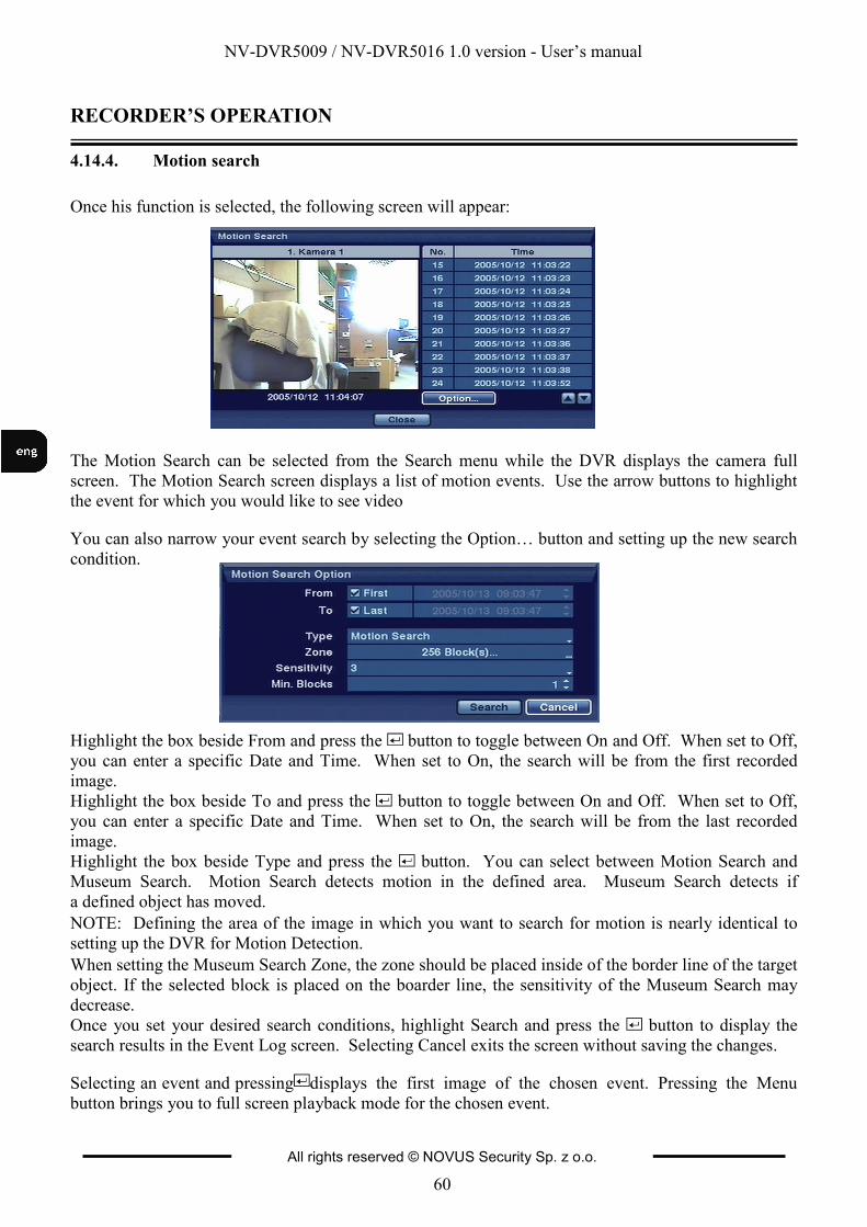
NV-DVR5009 / NV-DVR5016 1.0 version - User’s manual
All rights reserved © NOVUS Security Sp. z o.o.
60
RECORDER’S OPERATION
4.14.4. Motion search
Once his function is selected, the following screen will appear:
The Motion Search can be selected from the Search menu while the DVR displays the camera full
screen. The Motion Search screen displays a list of motion events. Use the arrow buttons to highlight
the event for which you would like to see video
You can also narrow your event search by selecting the Option… button and setting up the new search
condition.
Highlight the box beside From and press the button to toggle between On and Off. When set to Off,
you can enter a specific Date and Time. When set to On, the search will be from the first recorded
image.
Highlight the box beside To and press the button to toggle between On and Off. When set to Off,
you can enter a specific Date and Time. When set to On, the search will be from the last recorded
image.
Highlight the box beside Type and press the button. You can select between Motion Search and
Museum Search. Motion Search detects motion in the defined area. Museum Search detects if
a defined object has moved.
NOTE: Defining the area of the image in which you want to search for motion is nearly identical to
setting up the DVR for Motion Detection.
When setting the Museum Search Zone, the zone should be placed inside of the border line of the target
object. If the selected block is placed on the boarder line, the sensitivity of the Museum Search may
decrease.
Once you set your desired search conditions, highlight Search and press the button to display the
search results in the Event Log screen. Selecting Cancel exits the screen without saving the changes.
Selecting an event and pressing displays the first image of the chosen event. Pressing the Menu
button brings you to full screen playback mode for the chosen event.
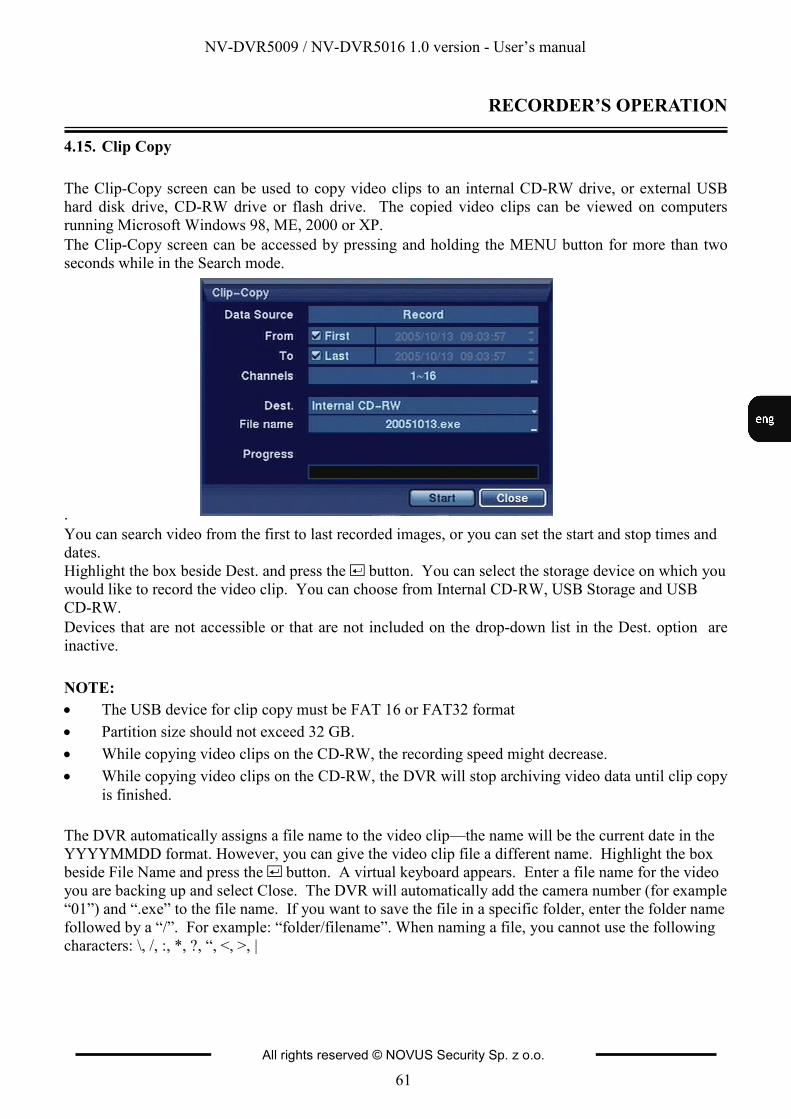
NV-DVR5009 / NV-DVR5016 1.0 version - User’s manual
All rights reserved © NOVUS Security Sp. z o.o.
61
RECORDER’S OPERATION
4.15. Clip Copy
The Clip-Copy screen can be used to copy video clips to an internal CD-RW drive, or external USB
hard disk drive, CD-RW drive or flash drive. The copied video clips can be viewed on computers
running Microsoft Windows 98, ME, 2000 or XP.
The Clip-Copy screen can be accessed by pressing and holding the MENU button for more than two
seconds while in the Search mode.
.
You can search video from the first to last recorded images, or you can set the start and stop times and
dates.
Highlight the box beside Dest. and press the button. You can select the storage device on which you
would like to record the video clip. You can choose from Internal CD-RW, USB Storage and USB
CD-RW.
Devices that are not accessible or that are not included on the drop-down list in the Dest. option are
inactive.
NOTE:
• The USB device for clip copy must be FAT 16 or FAT32 format
• Partition size should not exceed 32 GB.
• While copying video clips on the CD-RW, the recording speed might decrease.
• While copying video clips on the CD-RW, the DVR will stop archiving video data until clip copy
is finished.
The DVR automatically assigns a file name to the video clip—the name will be the current date in the
YYYYMMDD format. However, you can give the video clip file a different name. Highlight the box
beside File Name and press the button. A virtual keyboard appears. Enter a file name for the video
you are backing up and select Close. The DVR will automatically add the camera number (for example
“01”) and “.exe” to the file name. If you want to save the file in a specific folder, enter the folder name
followed by a “/”. For example: “folder/filename”. When naming a file, you cannot use the following
characters: \, /, :, *, ?, “, <, >, |
NV-DVR5009 / NV-DVR5016 1.0 version - User’s manual
All rights reserved © NOVUS Security Sp. z o.o.
62
RECORDER’S OPERATION
Once you have given the video clip a file name, highlight the Start button and press the button to
start clip copy. When the storage device does not have enough space, the DVR will ask if you want to
copy as much of the video clip as possible on the available space.
You can watch the progress strip to observe the progress of copying.
Appropriate message will appear once the copying process is completed.
NOTE: Do not copy video clips larger than 2GB .
You can use other functions on the DVR while video is being backed up. To do this, highlight the
Close button and press the button. You can return to the Clip-Copy screen at any time to check the
progress.
NOTE: During Clip Copy, you cannot shut the system down, clear data on the storage device, or format the storage device.
CAUTION: Do NOT disconnect the USB cable or the power from the external drive while copying video clips. If the external drive is shut down or the USB cable is disconnected while copying video
clips, THE DVR SYSTEM MAY NOT WORK NORMALLY OR THE EXTERNAL DRIVE COULD
BE DAMAGED, and you will get an error message the next time you try to copy video clips. You will
need to power down the DVR and restart it to get rid of the error message. Once the file system of the
USB-IDE hard disk drive has been corrupted, this error message cannot be dismissed. Even after
restarting the DVR it may automatically restart while preparing to clip copy. You must recover the file
system using the recovery program, or you must reformat the hard disk drive.
4.16. Print Screen
You can print images from the screen. Connect a printer to one of the USB ports. A message appears
asking you if you want to print the current image.
NOTE: If your printer only supports an LPT connection (parallel), use a LPT to USB converter cable. The printer cable is not provided.
Once the playback menu is entered, the playback action is automatically stopped. In case the printer is
connected and Print option is selected, the user will be asked to confirm the printing of the currently
displayed image.
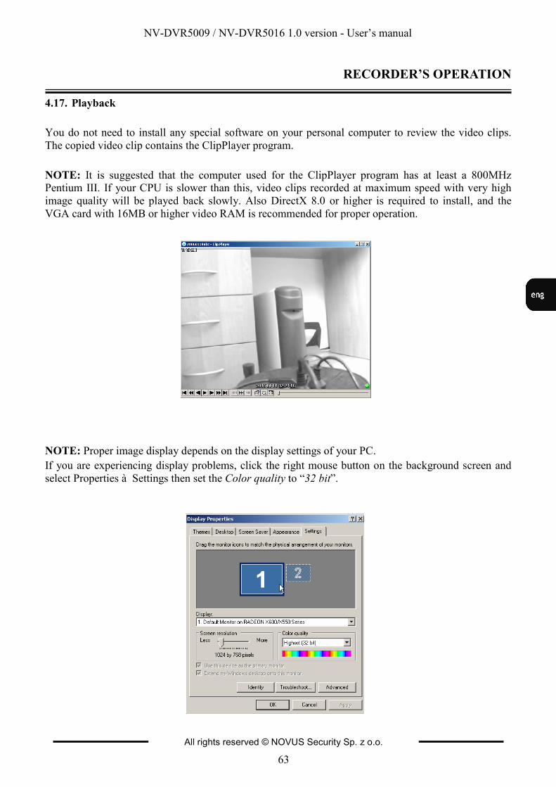
NV-DVR5009 / NV-DVR5016 1.0 version - User’s manual
All rights reserved © NOVUS Security Sp. z o.o.
63
RECORDER’S OPERATION
4.17. Playback
You do not need to install any special software on your personal computer to review the video clips.
The copied video clip contains the ClipPlayer program.
NOTE: It is suggested that the computer used for the ClipPlayer program has at least a 800MHz Pentium III. If your CPU is slower than this, video clips recorded at maximum speed with very high
image quality will be played back slowly. Also DirectX 8.0 or higher is required to install, and the
VGA card with 16MB or higher video RAM is recommended for proper operation.
NOTE: Proper image display depends on the display settings of your PC.
If you are experiencing display problems, click the right mouse button on the background screen and
select Properties à Settings then set the Color quality to “32 bit”.
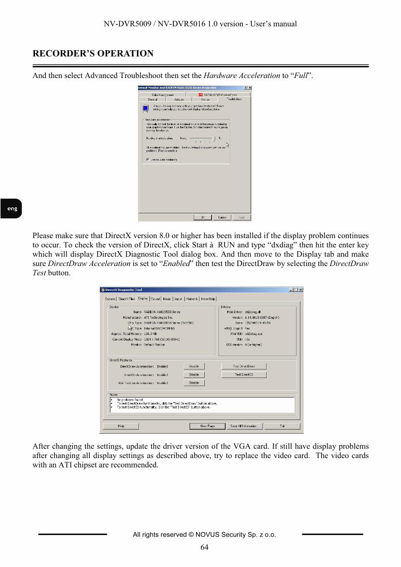
NV-DVR5009 / NV-DVR5016 1.0 version - User’s manual
All rights reserved © NOVUS Security Sp. z o.o.
64
RECORDER’S OPERATION
And then select Advanced Troubleshoot then set the Hardware Acceleration to “Full”.
Please make sure that DirectX version 8.0 or higher has been installed if the display problem continues
to occur. To check the version of DirectX, click Start à RUN and type “dxdiag” then hit the enter key
which will display DirectX Diagnostic Tool dialog box. And then move to the Display tab and make
sure DirectDraw Acceleration is set to “Enabled” then test the DirectDraw by selecting the DirectDraw
Test button.
After changing the settings, update the driver version of the VGA card. If still have display problems
after changing all display settings as described above, try to replace the video card. The video cards
with an ATI chipset are recommended.
NV-DVR5009 / NV-DVR5016 1.0 version - User’s manual
All rights reserved © NOVUS Security Sp. z o.o.
65
RECORDER’S OPERATION
Program functions description:
Clicking the X exits the Player program.
Click the to go to the beginning of the video clip.
Click the to play the video clip in fast reverse. Click the to go back one frame of the video clip. Click the to play the video clip. Click the to go forward one frame of the video clip.
Click the to play the video clip in fast forward. Click the to go to the end of the video clip.
Click the to show the previous page.
Click the to cycle through the screen layouts. It cycles through 2x2, 3x3 and 4x4.
Click the to show the next page.
By highlighting Image processing you can save images in the form of BMP format, print them or get
file information (cameras, the name of camera input, time, type, size, resolution).
Image processing function (brightness, blurring, sharpness) is not available in split.
Click the to select from Normal, Double and Full Screen views.
Encryption icons display in bottom-right corner. indicates the clip file has not been tampered with,
and indicates the system has detected tampering.
NOTE: If the VGA card or monitor for your PC does not support 640x480 video resolution, Full Screen might not display properly when selected. If this happens, press the ESC key on your PC to
return to the normal screen mode.
Placing the mouse cursor on an image and clicking will cause that image to display full frame.
NOTE: Do not run more than one ClipPlayer on a PC, otherwise the ClipPlayer will not operate properly.
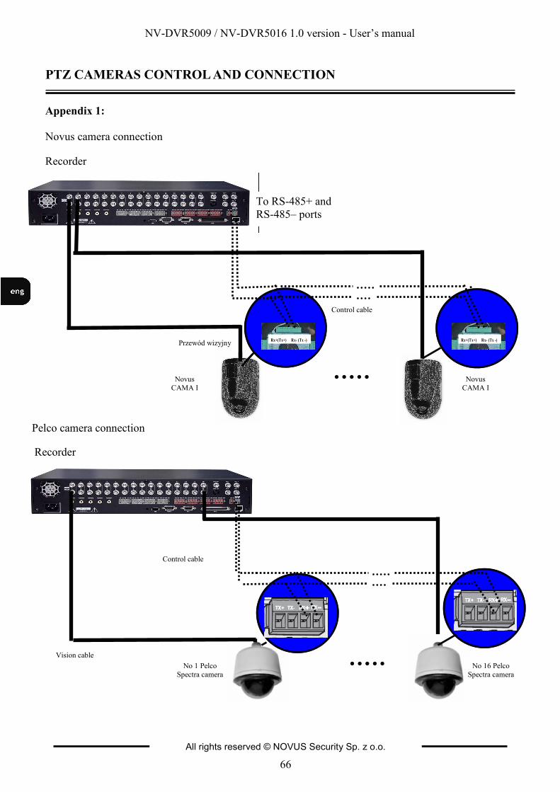
NV-DVR5009 / NV-DVR5016 1.0 version - User’s manual
All rights reserved © NOVUS Security Sp. z o.o.
66
PTZ CAMERAS CONTROL AND CONNECTION
Pelco camera connection
Appendix 1:
Novus camera connection
No 1 Pelco
Spectra camera
Vision cable
No 16 Pelco
Spectra camera
Control cable
Recorder
Novus
CAMA I
Przewód wizyjny
Control cable
Recorder
Novus
CAMA I
Rx+(Tx+) Rx- (Tx -) Rx+(Tx+) Rx- (Tx -)
To RS-485+ and
RS-485– ports
NV-DVR5009 / NV-DVR5016 1.0 version - User’s manual
All rights reserved © NOVUS Security Sp. z o.o.
67
CONNECTING DEVICES TO ALARM INPUTS AND OUTPUTS
Appendix 2:
Connecting devices to alarm inputs and outputs.
NV-DVR5009 and NV-DVR5016 recorders have 9 or 16 alarm inputs and out allowing you to connect
external devices. Connectors to plug in cables are equipped with handy clamp terminals.
NOTE: Both alarm inputs and outputs are not protected against any results of atmospheric discharges. The user has to make sure that the inputs are protected against discharges, which may damage the
inputs permanently.
Current load capacity of each alarm input cannot exceed 5mA for 12 V DC voltage and 30 mA for
5 V DC voltage. Directly to outputs you can connect e.g. LED (light-emitting diode) creating a circuit
(as presented on the chart below) for each output. If there is a need to connect devices which demand a
lot of current you have to use additional circuits (e.g. with a transmitter). Outputs can work as normally
closed or normally open.
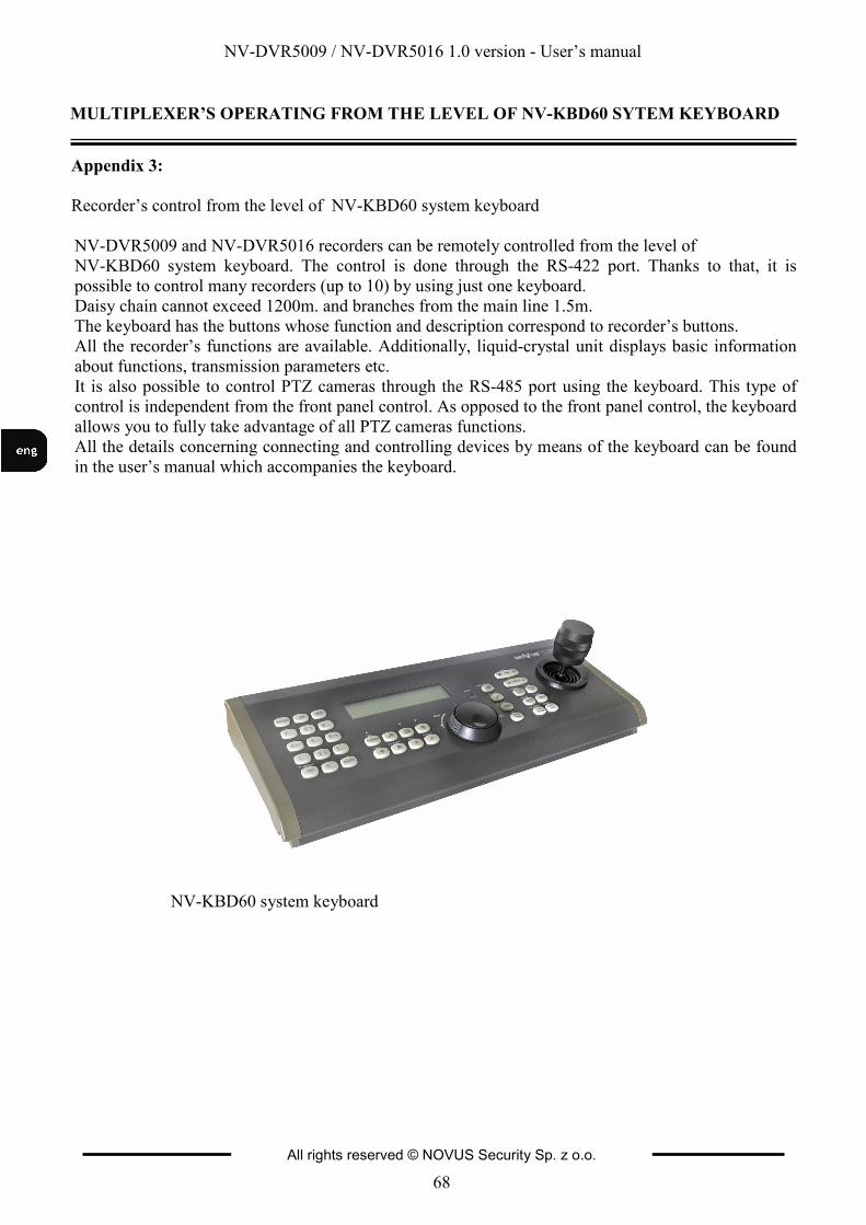
NV-DVR5009 / NV-DVR5016 1.0 version - User’s manual
All rights reserved © NOVUS Security Sp. z o.o.
68
Appendix 3:
Recorder’s control from the level of NV-KBD60 system keyboard
NV-DVR5009 and NV-DVR5016 recorders can be remotely controlled from the level of
NV-KBD60 system keyboard. The control is done through the RS-422 port. Thanks to that, it is
possible to control many recorders (up to 10) by using just one keyboard.
Daisy chain cannot exceed 1200m. and branches from the main line 1.5m.
The keyboard has the buttons whose function and description correspond to recorder’s buttons.
All the recorder’s functions are available. Additionally, liquid-crystal unit displays basic information
about functions, transmission parameters etc.
It is also possible to control PTZ cameras through the RS-485 port using the keyboard. This type of
control is independent from the front panel control. As opposed to the front panel control, the keyboard
allows you to fully take advantage of all PTZ cameras functions.
All the details concerning connecting and controlling devices by means of the keyboard can be found
in the user’s manual which accompanies the keyboard.
MULTIPLEXER’S OPERATING FROM THE LEVEL OF NV-KBD60 SYTEM KEYBOARD
NV-KBD60 system keyboard
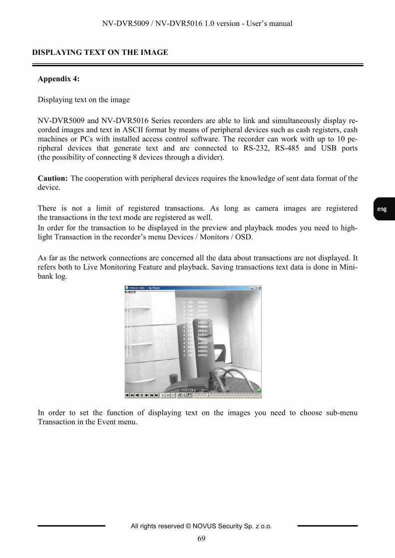
NV-DVR5009 / NV-DVR5016 1.0 version - User’s manual
All rights reserved © NOVUS Security Sp. z o.o.
69
MULTIPLEXER’S OPERATING FROM THE LEVEL OF NV-KBD60 SYTEM KEYBOARD
OBSŁUGA REJESTRATORA Z POZIOMU KLAWIATURY SYSTEMOWEJ NV-KBD60
Appendix 4:
Displaying text on the image
NV-DVR5009 and NV-DVR5016 Series recorders are able to link and simultaneously display re-
corded images and text in ASCII format by means of peripheral devices such as cash registers, cash
machines or PCs with installed access control software. The recorder can work with up to 10 pe-
ripheral devices that generate text and are connected to RS-232, RS-485 and USB ports
(the possibility of connecting 8 devices through a divider).
Caution: The cooperation with peripheral devices requires the knowledge of sent data format of the device.
There is not a limit of registered transactions. As long as camera images are registered
the transactions in the text mode are registered as well.
In order for the transaction to be displayed in the preview and playback modes you need to high-
light Transaction in the recorder’s menu Devices / Monitors / OSD.
As far as the network connections are concerned all the data about transactions are not displayed. It
refers both to Live Monitoring Feature and playback. Saving transactions text data is done in Mini-
bank log.
In order to set the function of displaying text on the images you need to choose sub-menu
Transaction in the Event menu.
DISPLAYING TEXT ON THE IMAGE
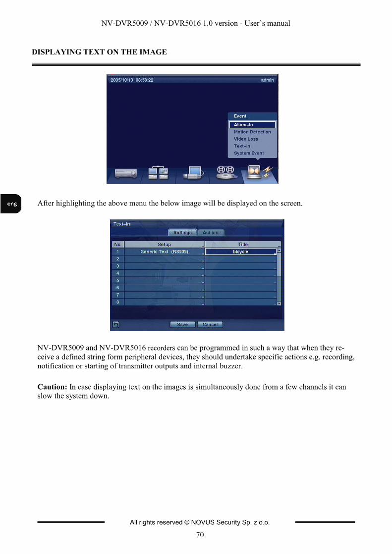
NV-DVR5009 / NV-DVR5016 1.0 version - User’s manual
All rights reserved © NOVUS Security Sp. z o.o.
70
DISPLAYING TEXT ON THE IMAGE
After highlighting the above menu the below image will be displayed on the screen.
NV-DVR5009 and NV-DVR5016 recorders can be programmed in such a way that when they re-
ceive a defined string form peripheral devices, they should undertake specific actions e.g. recording,
notification or starting of transmitter outputs and internal buzzer.
Caution: In case displaying text on the images is simultaneously done from a few channels it can slow the system down.
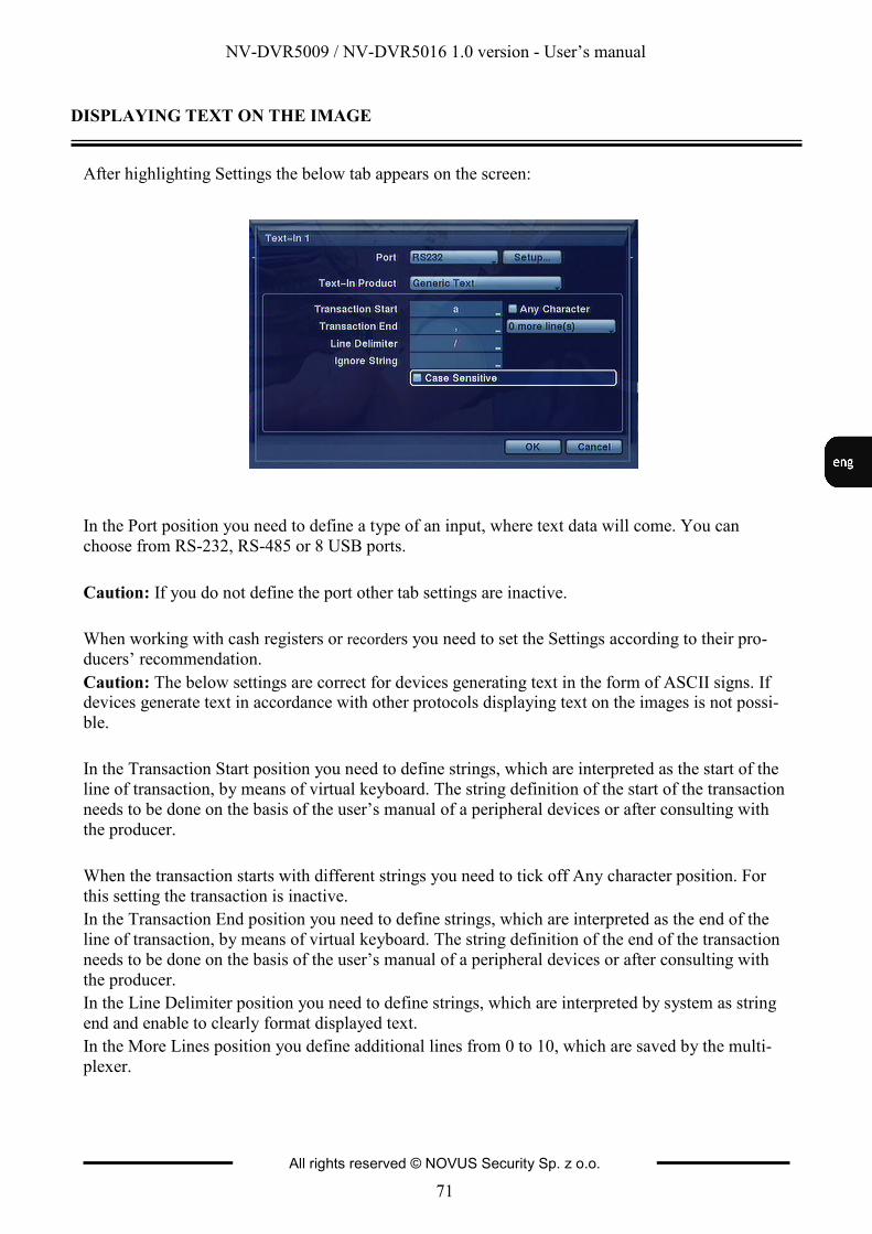
NV-DVR5009 / NV-DVR5016 1.0 version - User’s manual
All rights reserved © NOVUS Security Sp. z o.o.
71
DISPLAYING TEXT ON THE IMAGE
After highlighting Settings the below tab appears on the screen:
In the Port position you need to define a type of an input, where text data will come. You can
choose from RS-232, RS-485 or 8 USB ports.
Caution: If you do not define the port other tab settings are inactive.
When working with cash registers or recorders you need to set the Settings according to their pro-
ducers’ recommendation.
Caution: The below settings are correct for devices generating text in the form of ASCII signs. If devices generate text in accordance with other protocols displaying text on the images is not possi-
ble.
In the Transaction Start position you need to define strings, which are interpreted as the start of the
line of transaction, by means of virtual keyboard. The string definition of the start of the transaction
needs to be done on the basis of the user’s manual of a peripheral devices or after consulting with
the producer.
When the transaction starts with different strings you need to tick off Any character position. For
this setting the transaction is inactive.
In the Transaction End position you need to define strings, which are interpreted as the end of the
line of transaction, by means of virtual keyboard. The string definition of the end of the transaction
needs to be done on the basis of the user’s manual of a peripheral devices or after consulting with
the producer.
In the Line Delimiter position you need to define strings, which are interpreted by system as string
end and enable to clearly format displayed text.
In the More Lines position you define additional lines from 0 to 10, which are saved by the multi-
plexer.

NV-DVR5009 / NV-DVR5016 1.0 version - User’s manual
All rights reserved © NOVUS Security Sp. z o.o.
72
DISPLAYING TEXT ON THE IMAGE
In the Ignore position you define strings, whose detection is totally ignored by the system.
If there are both small and capital letters of different characteristic in the system you need to tick off
Case Sensitive.
Transaction search
The recorder saves text generated by connected peripheral devices in the data-base register. If you
want to set Transaction Search you need to highlight Option. The following screen appears:
In the From To positions you define time range of the search and camera channels, to which the
search refers. Next, you need to define keywords, which are searched for in the data-base register.
Simultaneously you can conduct the search according to 5 keywords. After ticking off Case Sensi-
tive the search criterion takes into account small and capital letters of the defined keyword.
After highlighting Search and pressing Enter the screen with search results is displayed.
NV-DVR5009 / NV-DVR5016 1.0 version - User’s manual
All rights reserved © NOVUS Security Sp. z o.o.
73
DISPLAYING TEXT ON THE IMAGE
After choosing a required result and choosing Enter the first image of a registered transaction with a
keyword is displayed. By choosing PLAY you start playback of the registered material connected
with the transaction. By choosing STOP you switch to Live Monitoring.
Caution: in case of images played back on the screen you need to choose 4x4 display mode in or-der to quickly find recorded images.
In order to filter required events you need to use Option. After choosing Option the following
screen appears:
Caution: Text information will be displayed on the image only in case of their playback at a stan-dard speed x1 and in the full screen view!!!
NV-DVR5009 / NV-DVR5016 1.0 version - User’s manual
All rights reserved © NOVUS Security Sp. z o.o.
74
NOVUS Security Sp. z o.o. ul. Puławska 431, 02-801 Warszawa
tel.: (22) 546 0 700, fax: (22) 546 0 719 www.novuscctv.com
2006-02-08
v. 1.0