npca detention/retention calculator user manual
TRANSCRIPT

August 10, 2010
NPCA Detention/Retention Calculator User Manual
Precast Concrete Stormwater Detention/Retention Calculator
Precast concrete manufacturers, working in conjunction with trade associations like the National Precast Concrete Association, have developed tools to simplify calculations that engineers typically use in designing stormwater systems. One of these is the Stormwater Detention/Retention Calculator. Here’s how it works:
Imagine you have a project that requires a very shallow stormwater conveyance system with less than 18 inches of cover in a limited space. One of the key components of the system is a subsurface stormwater detention reservoir to hold the stormwater and allow for a controlled discharge from the site at a lower flow rate. However, in reviewing the specs, you find that you are required to have at least 18 inches of cover on the product to meet traffic loading requirements in the parking lot.
Precast manufacturers have developed a solution for exactly this situation. Whether you need a detention or infiltration system for your project, a precast concrete structure can be designed for minimal cover depths and can be designed as an open or closed system.
Once you have chosen precast as the best material for your design, how do you size it for your project specifications, and what standard sizes are available? The NPCA Stormwater Management Committee recognized this as a problem and developed an Excel-based tool for just this situation. The tool is an interactive detention/retention calculator that enables the local manufacturer to add his standard products to your spreadsheet for easy use by the design engineer.
The tool simplifies calculations needed to specify stormwater structures for underground detention/retention systems and is available online at www.precast.org. You can find it by entering the Precast Solutions portal, choosing Products, Sanitary and Stormwater Products, Stormwater Management, and then clicking on Detention Calculator in the Resources section.
“The Precast Concrete Detention Calculator is an Excel-based tool that simplifies calculations needed to specify stormwater structures for underground detention and retention systems.”
August 10, 2010
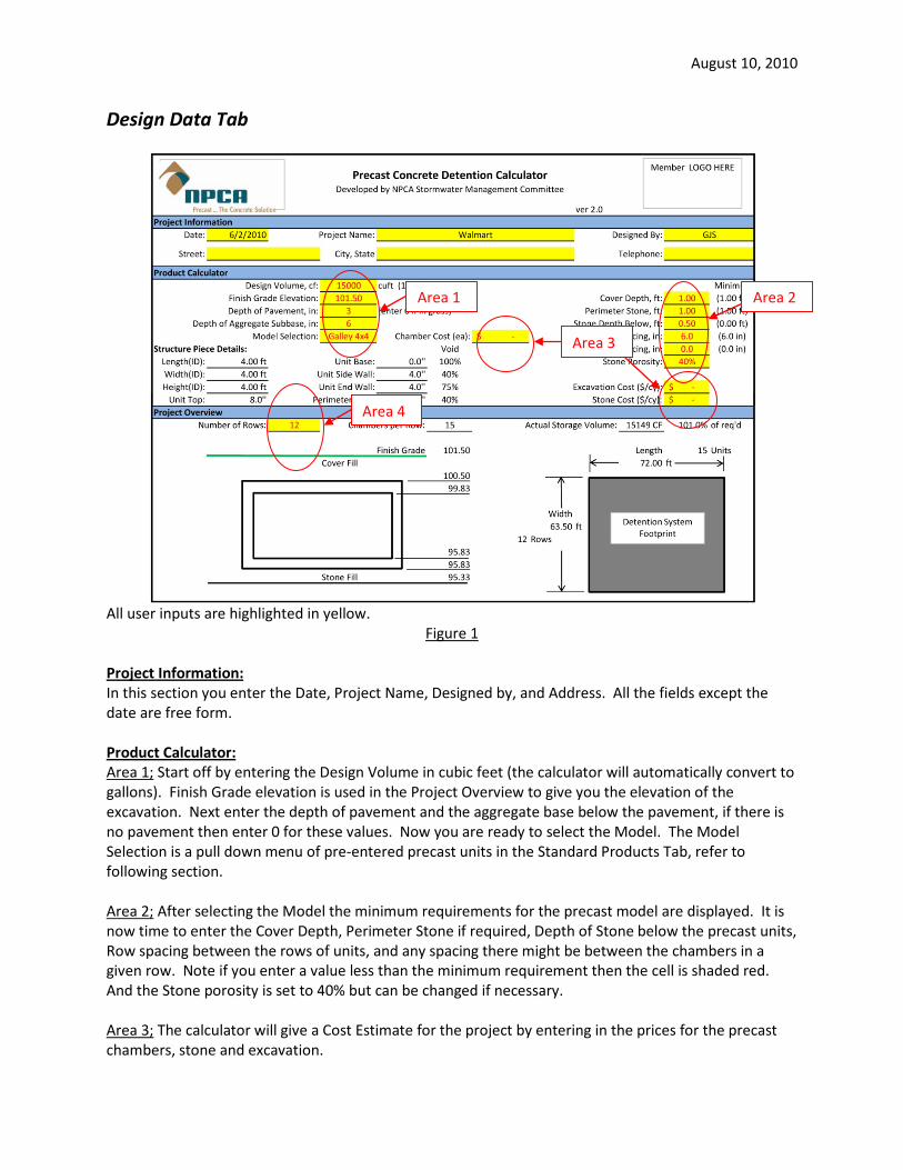
Design Data Tab
All user inputs are highlighted in yellow.
Figure 1 Project Information: In this section you enter the Date, Project Name, Designed by, and Address. All the fields except the date are free form. Product Calculator: Area 1; Start off by entering the Design Volume in cubic feet (the calculator will automatically convert to gallons). Finish Grade elevation is used in the Project Overview to give you the elevation of the excavation. Next enter the depth of pavement and the aggregate base below the pavement, if there is no pavement then enter 0 for these values. Now you are ready to select the Model. The Model Selection is a pull down menu of pre-entered precast units in the Standard Products Tab, refer to following section. Area 2; After selecting the Model the minimum requirements for the precast model are displayed. It is now time to enter the Cover Depth, Perimeter Stone if required, Depth of Stone below the precast units, Row spacing between the rows of units, and any spacing there might be between the chambers in a given row. Note if you enter a value less than the minimum requirement then the cell is shaded red. And the Stone porosity is set to 40% but can be changed if necessary. Area 3; The calculator will give a Cost Estimate for the project by entering in the prices for the precast chambers, stone and excavation.
Area 2 Area 1
Area 4
Area 3

August 10, 2010
Area 4; Select the number of rows to determine the size of the underground pond. The calculator then determines the length of the rows. The foot print of the underground pond can be changed by varying the number of rows. Project Overview: Under the Structure Piece Detail you can change the number of rows, of units, used in the detention field. Refer to the Project Overview section and adjust the number of rows until the detention footprint is satisfactory. This section also illustrates the elevations of finish grade, top of chamber, inside height elevation, floor elevation, outside bottom of chamber and bottom elevation for excavation. Product Summary: Page 2, refer to figure 2, of the Design Data Tab gives a summary of the underground pond along with the quantity and cost of chambers and quantity of stone required. The design and actual storage volume is also calculated, a blue highlight in the Actual Storage Volume cell indicates a pass and red is a fail. On this page there is also an illustration showing the dimensions of the actual chamber.
Figure 2

August 10, 2010
Incremental Volume Tab The incremental volume calculator can be used to determine the volume of storage in the underground pond at different elevations. For example, this information can be used to calculate the inverts at which outlet pipes and over flow orifices may be required during heavy storm events. There is only one data entry point on this tab, which is the reference elevation for the incremental volume table. The table below only displays the 36 inches from the reference point. Therefore if the reference point (or starting point) is 1” then the table goes up to 36 inches. For example, if I am interested in knowing the volume at 20” of liquid level in the detention field, then I will set the reference point to 1 and determine that the volume at 20” is 7296.73 cubic feet. Also this tab gives detail information on the chambers and the elevations in the detention field.

August 10, 2010
Standard Product Tab All the information about the different Precast Chambers (Models) are entered in this tab. Define the Model Name and Chamber Type. The Chamber Type is a pull down menu with three options; Individual Units, Box Culvert 4-sided and Box Culvert 3-sided. Next is length, width and height. These are all inside dimensions of the individual units. Set length to 0 for Box Culvert since the calculator will determine the entire length of the row. Enter the Top and Base Slab thicknesses. The voids illustrate the percentage of how much of the floor or sides is porous (drain holes). The table also refers to three different walls; the End Wall which is the thickness of the wall where the chambers but up against each other in the same row. The Side wall is the wall on the sides of the chambers between each row. The perimeter wall is the wall around the outside of the field. This allows the interior walls to have different dimensions than the perimeter walls. Also not that on Box Culverts the end wall thickness is usually 0, because they are placed together to form a tunnel. Once you have entered all information for a Model you can select a model from the pull down menu (yellow highlighted area) and view all the dimensions shown in the illustration.

August 10, 2010
Narration for Video Tutorials
Calculator Introduction (7 minutes): The precast concrete detention calculator is an Excel based tool that simplifies calculations needed to specify stormwater structures for underground detention and retention systems. To begin using the calculator under the Detention Calculator Tab you can enter in project information; enter the date, project name, and designer. These are all free form fields. You can also enter in the address information. Next step is to enter in the design volume in cubic feet that you have previously determined for your underground pond. For example let’s put in 15000 cubic feet. You can also see that it converts it to gallons. Next enter in some elevation information that will be used later by the calculator. For example finished grade is at 101.5, the pond is under a paved area so there is 3 inches of pavement, otherwise enter zero for a grassy area. For the depth of aggregate below pavement let’s use 6 inches. Next is Model Selection. For this example we will select Galley 4x4 from the pull down menu. Once you have chosen a model the calculator enters in information about the dimensions and minimum requirements for the chamber. All this information is entered in the Standard Products Tab of the calculator. We will discuss the Standard Products Tab in more detail later. Next we will verify the minimum requirements; depth of cover, stone perimeter, stone base below chambers (we will enter 6 inches this will aid the contractor in creating a level base for setting the chambers), row spacing (distance between rows of chambers), chamber spacing (distance between chambers in a given row). Red highlights indicate that you have selected a value less than the default minimum requirements. The calculator will run but it is giving you an alert that indicates there may be a possible problem with your selection. If you would like to have a Cost Estimate, enter in the pricing for the units, stone and excavation. The calculator will determine the total cost and display the information on page two. Next it is time to determine the foot print of the underground pond. The Project Overview sections gives you diagram showing the elevations and the detention system foot print. We allow you to select the number of rows and the calculator determines the length of the rows and the foot print of the underground system. If the dimensions of the foot print don’t work then you can change the foot print by changing the number of rows. Notice that the floor and outside bottom elevations are the same; this is due to the fact that the model selected does not have a floor (open bottom system). With a half foot of stone base you will notice that the bottom elevation is 95.33, which is the excavation limit for placing the stone base. Moving on to page two, you will notice it is more of a summary. You will see there is a list of the units that make up the underground system. There is the storage of the units with and without stone, and then it compares the actual volume to the design volume. If the actual volume is less than the design volume, the field is red which indicates there may have been some erroneous data entered. Blue indicates that the design has passed. At the bottom it indicates total quantities of chambers, stone and excavation. And if the costs were entered then it will give you a total estimate. Also there is a diagram illustrating the dimensions of an individual chamber.

August 10, 2010
Incremental Volume Calculator (4 minutes): In this section we will discuss the use of the Incremental Volume Calculator. The first tab is the Design Data Tab that we used to enter in all the information about the underground system. On the Incremental Volume tab you will see that we have all the project information, model selection with data, storage information, and system elevations. The incremental calculator will display the volume of the underground system at different elevations. This information can be used for many situations; you may have an overflow outlet at a certain volume, what the elevation is at 10, 50 100 year storm events. The first thing that you need to do is start off with a reference point. The first 36 inches from your reference point will be displayed. For example you may want to know what the volume is between 1 and 20 inches for the underground pond. Therefore 1 inch is entered for the starting reference. You will see that the volume is displayed from the bottom of the underground pond and up in 1 inch increments, refer to table. If you need to view more than the first 36 inches (chamber may be 48 inches), then change the reference to higher value. Once you have reached the top of chamber notice that the volume stops increasing as you go up due to the fact you have reached maximum storage. Notice that on even higher elevations the first column changes color to indicate you are now above top of chamber elevation. Also notice that we have a stone base of .5 feet, if you refer to bottom of chart you will see the column is color coded for storage below chambers. Box Culvert Model Selection (4 minutes): This example will show what to do if the model selection is a box culvert. We have entered the project information and now it is time to select a box culvert 8’x10’. Enter in minimum requirements; cover equal to 1 foot. Enter zero for perimeter, sub base, row spacing, and chamber spacing. Again as before select the number of rows then evaluate the foot print. Refer to project overview for elevations and foot print of underground system. Page 2 is the project summary. Notice that we have the number of rows indicated, but the number of units per row is TBDL. You have been given the total length of the row but the actual length of the individual units would be determined by the local precaster. Standard Products Tab (8 minutes): This tab allows you to enter in all the standard precast items that you would like to have available for selection in the Precast Concrete Detention Calculator. Refer to the notes before entering information. The calculator allows for different thicknesses and voids on the inside walls and perimeter walls. You also need to enter in percentage of voids for the walls and floor. This allows you to enter in open bottom and/or leaching chambers in the products tab. There are three different types of chambers that we classify; Individual Units, your basic square/cube type structure, has four walls could be solid or perforated. Next type is a box culvert 3 or 4 sided structure. The sections are normally connected together to form one continuous tunnel. When entering in box culvert information make sure the length is set to zero. Row spacing is the distance between each row of chambers and chamber spacing is the distance between chambers in a given row. Under some cases the spacing is zero, for example box culvert usually is zero for both. Enter in an example using a 3x8 box culvert and drywell 4x8. At the top of the Product tab you will see a diagram of an underground pond. From the pull down menu you can select a model to display in the diagram. The diagram will illustrate exactly what each of the dimensions are from the table below. Once you have entered in the Standard Products you can select which model you need in the Detention Calculator Tab.