npd bead replacement - agilent.com · 3 replacing the npd bead instruction guide agilent...
TRANSCRIPT

Agilent Technologies
Replacing the NPD Bead
Instruction Guide

2 Instruction Guide
Notices© Agilent Technologies, Inc. 2004
No part of this manual may be reproduced in any form or by any means (including elec-tronic storage and retrieval or translation into a foreign language) without prior agree-ment and written consent from Agilent Technologies, Inc. as governed by United States and international copyright laws.
Manual Part NumberG1534-90318
EditionFirst Edition, March 2004
Printed in USA
Agilent Technologies, Inc.2850 Centerville Road Wilmington, DE 19808-1610 USA
Warranty
The material contained in this docu-ment is provided “as is,” and is sub-ject to being changed, without notice, in future editions. Further, to the max-imum extent permitted by applicable law, Agilent disclaims all warranties, either express or implied, with regard to this manual and any information contained herein, including but not limited to the implied warranties of merchantability and fitness for a par-ticular purpose. Agilent shall not be liable for errors or for incidental or consequential damages in connec-tion with the furnishing, use, or per-formance of this document or of any information contained herein. Should Agilent and the user have a separate written agreement with warranty terms covering the material in this document that conflict with these terms, the warranty terms in the separate agreement shall control.
Safety Notices
CAUTION
A CAUTION notice denotes a haz-ard. It calls attention to an operat-ing procedure, practice, or the like that, if not correctly performed or adhered to, could result in damage to the product or loss of important data. Do not proceed beyond a CAUTION notice until the indicated conditions are fully understood and met.
WARNING
A WARNING notice denotes a hazard. It calls attention to an operating procedure, practice, or the like that, if not correctly per-formed or adhered to, could result in personal injury or death. Do not proceed beyond a WARNING notice until the indicated condi-tions are fully understood and met.

3
Replacing the NPD BeadInstruction Guide
Agilent Technologies
Replacing the NPD Bead
6820 and 6890 Gas Chromatographs
This instruction guide reviews the procedure for installing a bead on a nitrogen-phosphorus detector (NPD). Before following this procedure, refer to the safety information on the inside front cover.
Parts list
• 1 NPD bead assembly
• Cap for the bead
• Test chromatogram
Required tools
• T-10 Torx screwdriver
CAUTION The ceramic bead is delicate. Be careful not to break or crack the bead. When you perform maintenance on the NPD, avoid touching the bead with your fingers, and prevent it from coming in contact with other surfaces.
WARNING Be careful! The oven or detector fittings may be hot enough to cause burns.

4 Instruction Guide
Replacing the NPD Bead
Steps
1 Preparing the GC
2 Removing the old bead and installing a new bead
3 Turning the bead on
Figure 1 NPD on a 6890 GC
Cable
Metal hex
Bead (source)
Connector
3 T-10 Torx screws

Replacing the NPD Bead
Instruction Guide 5
Preparing the GC
1 Set the NPD Bead Voltage to 0.0. (Do not set it to "off".)
2 Cool the NPD to below 100 °C. Leave all gas flows on.
3 Remove the necessary GC covers.
• 6820: Remove the detector and right side covers.
WARNING Hazardous voltages are present in the mainframe when the GC power cord is plugged in. Avoid a potentially dangerous shock hazard by unplugging the power cord before removing the side panels.
NOTE ChemStation Users: The bead voltage cannot be set to zero from the ChemStation. You must use the GC Keypad. In order to do this the keypad must be unlocked and you must close the "Edit GC Parameters" screen of the ChemStation. After you have set the voltage to 0.0 save the method on the ChemStation and then shutdown the instrument session.
Temp 100 24H2 flow 3.0 3.0
FRONT DET (NPD)Air flow 60.0 60.0Mkup (He) 5.0 5.0 <Adjust offset OffOutput (Off) 0Bead voltage 0.0

6 Instruction Guide
Replacing the NPD Bead
• Early 6890 models: Raise the gray plastic top cover (with the holes and ventilation slots) to the vertical position. The hinge is a metal bracket attached to the oven top. Pull the clip at its top toward you to release the hinge pin. Push the pin to the left to release the cover. Raise the cover and remove it. Remove the top electronics cover. Push the clips underneath the cover (shown in Figure 2) toward the center to disengage them.
• Current 6890 models: Raise the plastic top cover and remove it. Remove the top electronics cover. Push the clips underneath the cover toward the center to disengage them.
Figure 2 Removing the top electronic cover (6890)
Clips
Replacing the NPD Bead
Instruction Guide 7
Removing and Installing the Bead
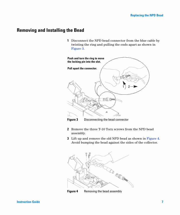
1 Disconnect the NPD bead connector from the blue cable by twisting the ring and pulling the ends apart as shown in Figure 3.
2 Remove the three T-10 Torx screws from the NPD bead assembly.
3 Lift up and remove the old NPD bead as shown in Figure 4. Avoid bumping the bead against the sides of the collector.
Figure 3 Disconnecting the bead connector
Figure 4 Removing the bead assembly
1 2
Push and turn the ring to movethe locking pin into the slot.
Pull apart the connector.

8 Instruction Guide
Replacing the NPD Bead
4 Uncap the new bead by pushing the cap off from the cable side (Figure 5). Make sure not to bump the bead on the sides of the cap.
5 Mount the new bead assembly on the NPD collector as shown in Figure 6. Be careful not to bump the bead on the sides of the collector. Use the three new Torx T-10 screws supplied. Tighten the first screw only finger-tight; tighten the remaining two screws normally and then completely tighten the first screw.
Figure 5 Uncapping the bead
Figure 6 Mounting the bead assembly
Screws
Collector

Replacing the NPD Bead
Instruction Guide 9
6 Carefully bend the bead assembly cable 90 degrees (Figure 7). You should support the cable as shown here.
7 Reconnect the bead assembly cable to the NPD cable as shown in Figure 8. Twist the ring to lock the connection.
Figure 7 Bending the bead assembly cable
Figure 8 Connecting the bead assembly cable
3
2
Push the two parts of the cabletogether.
Push and twist the ring to slidethe locking pin into place andlock.
1
2

Agilent Technologies
© Agilent Technologies, Inc.
Printed in USA, March 2004
8 Reinstall the GC covers.
9 With all gases on, start heating the detector to 150 °C. Allow it to remain at 150 °C for about 15 minutes, then proceed to heat it to 250 °C and allow it to remain here for about 15 minutes. Finally, heat the detector to 325 °C.
10 After temperature equilibration is reached, the bead voltage may be adjusted (0.0 V-2.00 V should be the range to start). If the auto adjust feature is used, set the detector equilibration time to 0.00 minutes (configure detector from keyboard).
11 The default offset is 30 picoamps (pA). A lower offset may be used to give longer bead life.
Turning on the bead
1 Turn on the GC power. (ChemStation users: restart the instrument session.)
2 Check that the NPD bead voltage is set to 0.0.
3 Verify that all other GC parameters are set correctly and wait for "Ready".
4 Set NPD "Adjust Offset" to desired output current (pA). Normally 30 pA is a good working output current. The auto adjust process will start. Once auto adjust is completed save your method.
G1534-90318

更换 NPD 铷珠
操作指南
Agilent Technologies

注意© 安捷伦科技有限公司 , 2004
根据美国和国际版权法,事先未经安捷伦科技公司书面许可,本书的任何部分不得以任何形式复制 (包括存储为电子版、修改和翻译成外文)。
手册部件号
G1534-90318
版本
2004 年 3 月第一版
美国印刷
安捷伦科技公司2850 Centerville Road Wilmington, DE 19808-1610 USA
声明
本书内容,在将来的版本中如有变动,恕不另行通知。安捷伦科技公司对本材料,及由此引出的任何商务和特殊用途不承担责任。安捷伦科技公司对本手册中可能有的错误或与装置、性能及材料使用有关内容而带来的意外伤害和问题不负任何责任。
如果安捷伦科技公司和用户对本书中的警告术语有不同的书面协议,这些术语与本书中的警告术语冲突,则以协议中的警告术语为准。
安全注意事项
小 心
小心提示表示危险。提醒您在操作过程中注意,如果执行不当,将影响产品或丢失重要数据。不要忽视小心提示,直到完全理解和符合所指出的条件。
警 告
警告提示表示危险。提醒您在操作过程中注意,如果执行不当,将导致人身伤害或死亡。不要忽视警告提示,直到完全理解和符合所指出的条件。
2 操作指南

更换 NPD 铷珠操作指南
更换 NPD 铷珠
6820 与 6890 气相色谱仪
,在
小 NPD
本操作指南综合说明在氮磷检测器(NPD)上安装铷珠的步骤按照这一步骤进行安装之前要参考本书封二的安全注意事项。
心 铷珠是易碎品,注意不要把它打碎或碰裂。在进行维护时,应避免用手指触摸铷珠,防止铷珠与其它表面接触。
告 当心!柱箱或检测器接头很热,会造成烫伤。
警
单
部件清• 1 个 NPD 铷珠组件
• 铷珠帽
• 测试色谱图
所需工具
• T-10 Torx 螺丝刀
3
Agilent Technologies
更换 NPD 铷珠
步骤
4
1 准备 GC
2 取下旧的铷珠并安装新铷珠
3 给铷珠通电
图 1 在 6890 上的 NPD
电缆
3颗 T-10 Torx 螺钉
金属六边体
铷珠(源)
连接头
操作指南

更换 NPD 铷珠
GC 的准备
操作指南
当 GC 电源线插在电源上时,主机上有危险电压。为了避免可能
警 告产生的电击危险,在卸下侧面板以前要把电源线插头拔下来。1 将 NPD 铷珠的电压设定为 0.0 (不要把它设定为 “off”)。
化学工作站用户:铷珠电压不能从化学工作站上设定为零,您必须
注 意使用 GC 键盘,为此,不能把键盘锁住,而且必须关闭化学工作站的 "Edit GC Parameters" (编辑 GC 参数)屏幕,在将电压设定为 0.0后,在化学工作站上存储方法,然后关闭仪器对话框部分。2 将 NPD 冷却到 100 °C 以下,使所有气体都保持开通。
3 卸下必要的 GC 仪器盖
• 6820 : 取下检测器和右侧的面板。
Temp 100 24H2 flow 3.0 3.0
FRONT DET (NPD)Air flow 60.0 60.0Mkup (He) 5.0 5.0 <Adjust offset OffOutput (Off) 0Bead voltage 0.0
5

6
更换 NPD 铷珠
• 早期的 6890 型号 : 将灰色的塑料上盖(带有孔和排气槽)抬起、竖起来。合页是连接到柱箱顶部的金属架,朝自己的方向拉其上面的卡子,松开合页的销子。把销子向左推,即可松开盖。抬起上盖,取下它。把电路元件的盖卸下来,把盖子下面的卡子推向中央 (如图 2 所示)使其脱离。
• 现在的 6890 型号 : 抬起灰色的塑料顶盖把它卸下来,把电路元件的上盖卸下来,把盖子下面的卡子推向中央使其脱离。
图 2 卸下电路部件上盖 (6890)
卡子
操作指南

更换 NPD 铷珠
卸下和安装铷珠
操作指南
1 拧动金属环拉出电缆头,从蓝色电缆上把 NPD 铷珠连接头拆下来,如图 3 所示。
2 从 NPD 铷珠组件上卸下三个 T-10 Torx 螺钉。
3 提起并取下旧的铷珠,如图 4 所示,避免铷珠与收集极的壁相碰。
图 3 拆下铷珠连接头
图 4 卸下铷珠组件
1 2
把连接头拔出来
推拧金属锁环以便把锁紧卡推到槽中
7

8
更换 NPD 铷珠
4 将盖从电缆一边推下,打开新铷珠的盖(图 5),注意不要让铷珠碰到盖的壁。
5 按照图 6 把新铷珠组件嵌在 NPD 收集极上。注意不要让铷珠碰到收集极的壁。装上仪器提供的三个新的 Torx T-10 螺钉。第一个螺钉只用手拧紧。再按正常方式拧紧其余两个螺钉,然后再把第一个螺钉彻底拧紧。
图 5 打开铷珠帽
图 6 安装铷珠组件
螺钉
收集极
操作指南

更换 NPD 铷珠
操作指南
6 小心将铷珠组件电缆弯曲成 90 度 (图 7),应如下图所示托住电缆。
7 将铷珠组件的电缆与 NPD 电缆重新连接起来,如图 8 所示,拧紧金属环锁紧连接头。
图 7 弯曲铷珠组件电缆
图 8 连接铷珠组件电缆
3
21
2
把电缆的两端推到一起
推拧金属环并把锁紧卡滑入位锁紧
9

Agilent Technologies
8 重新安装 GC 仪器盖。
9 使所有的气体处于开通状态,开始把检测器加热到 150 °C,并保持在 150 °C 约 15 min ,然后把检测器升温到 250 °C ,并在此温度下保持 15 min ,最后把铷珠加热到 325 °C。
10 在温度达到平衡后,可以打开铷珠的电压 (0.0 V-2.00 V,开始时一定要在这个范围),如果使用自动调节功能,设定检测器的平衡时间为 0.00 min (在键盘上配置检测器)。
11 默认偏移量为 30 皮安 (pA) 。可以使用较低的偏移量,以便延长铷珠的寿命。
给铷珠通电
1 给 GC 通电 (化学工作站用户:重新启动仪器的对话框)。
2 检查 NPD 铷珠的电压设定为 0.0。
3 检查对所有其他 GC 参数的设定正确,并等待 “就绪”。
4 设定 NPD 的 "Adjust Offset" 到所需的输出电流 (pA),正常情况下 30 pA 是较好的工作输出电流,自动程序将启动,一旦自动调节完成就存储您的方法。
© 安捷伦科技公司
2004 年 3 月美国印刷
G1534-90318

Agilent Technologies
NPD ビーズの交換
インストラクションガイド

2 インストラクションガイド
注意事項© Agilent Technologies, Inc. 2004
アメリカ合衆国著作権法および国際著作権法に定められているとおり、本書のいかなる部分も、Agilent Technologies, Inc. による事前の合意および書面による承諾なしに、いかなる形態であれ、いかなる方法によっても(電子記憶装置および検索、または外国語への翻訳を含む)複製することはできません。
マニュアル製品番号G1534-90318
版第 1 版(2004 年 3 月)
Printed in USA
Agilent Technologies, Inc.2850 Centerville Road Wilmington, DE 19808-1610 USA
保証
本書の内容は「現状のまま」提供され、今後予告なしに変更されることがあります。さらに、Agilentは、適用法上許容される最大限において、明示的または黙示的にかかわらず、本書および本書に含まれるあらゆる内容についていかなる保証(商品性および特定の目的のための適合性に関する黙示の保障を含む)も与えるものではありません。Agilent は、本書および本書に含まれるあらゆる内容の支給、使用、または実施に関連して生じた付随的損害、派生的損害または間接的損害を含めいかなる損害についても、責任を負いかねますのでご了承ください。Agilent とユーザー間に、本書の内容を対象とした保証条件に関する別個の契約書があり、上記の条件と異なる場合、別途定めた契約書の条件を適用します。
安全上の注意事項
注意
注意に関する記載事項は、危険を表します。正確に実行または順守しないと、製品の損傷や重要なデータの消失を引き起こす恐れがある操作手順や実行方法などに対して注意を促します。当該状況を把握し、対処するまで、注意に関する記載事項を無視して続行しないでください。
警告
警告に関する記載事項は、危険を表します。正確に実行しない、または順守しないと、けがや生命の危険を引き起こす恐れがある操作手順や実行方法などに対して注意を促します。示された状態を完全に理解し、対処するまで、警告に関する記載事項を無視して続行しないでください。

3
NPD ビーズの交換インストラクションガイド
Agilent Technologies
NPD ビーズの交換
6820 および 6890 ガス クロマトグラフ
本書では窒素リン検出器(NPD)のビーズを取り付ける手順を解説しています。本手順に進む前に、表紙裏の安全性に関する情報を参照してください。
部品リスト
• 1 個の NPD ビーズ アセンブリ
• ビーズ用キャップ
• テスト用クロマトグラフ
必須工具
• T-10 トルク ドライバー
注意セラミック ビーズは壊れやすいので、割ったり、ひびを入れたりしないように注意してください。NPD のメンテナンスを行うときは、指でビーズを触れたり、他の表面に接触させたりしないでください。
警告注意! オーブンまたは検出器のフィッティングはやけどの原因となる程に熱くなることがあります。

4 インストラクションガイド
NPD ビーズの交換
手順
1 GC の準備
2 古いビーズの取り外しと新しいビーズの取り付け
3 ビーズの作動
図 1 6890 GC の NPD
ケーブル
メタル六角
ビーズ(ソース)
コネクタ
3 個の T-10 トルク ネジ
NPD ビーズの交換
インストラクションガイド 5
GC の準備
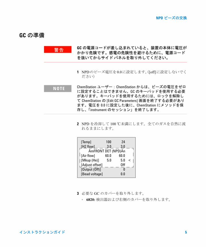
1 NPDのビーズ電圧を0.0に設定します。([off]に設定しないでください)
2 NPD を冷却して 100 ℃未満にします。全てのガスを自然に流れるままにします。
3 必要な GC のカバーを取り外します。
• 6820:検出器および右側のカバーを取り外します。
警告GC の電源コードが差し込まれていると、装置の本体に電圧がかかり危険です。感電の危険性を避けるために、電源コードを抜いてからサイド パネルを取り外してください。
NOTE ChemStation ユーザー:ChemStation からは、ビーズの電圧をゼロに設定することはできません。GC のキーパッドを使用する必要があります。キーパッドを使用するためには、ロックを解除して ChemStation の [Edit GC Parameters] 画面を終了する必要があります。電圧を 0.0 に設定した後に、ChemStation にメソッドを保存し、「instrument のセッション」を終了します。
[Temp] 100 24[H2 flow] 3.0 3.0
ÅmFRONT DET (NPD)Ån[Air flow] 60.0 60.0[Mkup (He)] 5.0 5.0 <[Adjust offset] Off[Output (Off)] 0[Bead voltage] 0.0

6 インストラクションガイド
NPD ビーズの交換
• 初期の 6890モデル:プラスチック製のグレイの上部カバー(穴および換気用のスロット付き)を垂直の位置に持ち上げます。カバーのヒンジはオーブンの上部に取り付けられた取り付け用金具です。上部のクリップを手前に引き、ヒンジのピンを緩めます。ピンを左に押してカバーを緩めます。カバーを持ち上げて取り外します。電子部品の上部のカバーを取り外します。カバー(図 2 に示す)の下部にあるクリップを中央方向に押して、クリップを外します。
• 現行の 6890モデル:プラスチック製の上部のカバーを持ち上げて取り外します。電子部品の上部のカバーを取り外します。カバーの下部にあるクリップを中央方向に押して、クリップを外します。
図 2 電子部品の上部カバー(6890)の取り外し
クリップ

NPD ビーズの交換
インストラクションガイド 7
ビーズの取り外しと取り付け
1 図 3 で示すように、リングをひねり両端部を引き離して、NPDのビーズ コネクタをブルーのケーブルから切り離します。
2 3個のT-10トルクネジをNPDのビーズ アセンブリから取り外します。
3 図 4 で示すように、古い NPD のビーズを持ち上げて取り外します。コレクタの両側にビーズをぶつけないようにします。
図 3 ビーズ コネクタの切り離し
図 4 ビーズ アセンブリの取り外し
1 2
リングを押して回転させ、ロック用
コネクタを切り離します。
のピンをスロットに差し込みます。

8 インストラクションガイド
NPD ビーズの交換
4 ケーブルの側(図 5)からキャップを押して取りはずし、新しいビーズのキャップを外します。キャップの側面にビーズがぶつからないことを確認します。
5 図 6 に示すように、新しいビーズ アセンブリを NPD のコレクタに取り付けます。コレクタの側面にビーズをぶつけないように注意します。供給された 3 個の新しいトルク T-10 ネジを使用します。最初のネジは指だけで軽く締めておき、残りの2 個のネジは通常どおりに締めます。次に、最初のネジを完全に締め付けます。
図 5 ビーズのキャップの取り外し
図 6 ビーズ アセンブリの取り付け
ネジ
コレクタ
NPD ビーズの交換
インストラクションガイド 9
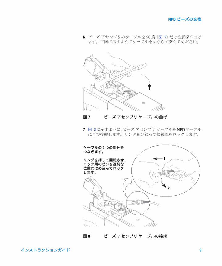
6 ビーズ アセンブリのケーブルを 90 度(図 7)だけ注意深く曲げます。下図に示すようにケーブルをかならず支えてください。
7 図 8に示すように、ビーズ アセンブリ ケーブルをNPDケーブルに再び接続します。リングをひねって接続部をロックします。
図 7 ビーズ アセンブリ ケーブルの曲げ
図 8 ビーズ アセンブリ ケーブルの接続
3
2
ケーブルの 2 つの部分を
リングを押して回転させ、 1
2
ロック用のピンを適切な位置にはめ込んでロックします。
つなぎます。

© Agilent Technologies, Inc.
Printed in USA, March 2004
Agilent Technologies
8 GC のカバーを再度取り付けます。
9 全てのガスを流した状態で、加熱を開始して検出器を 150 ℃にします。約 15 分間検出器を 150 ℃の状態を保ちます。次に、250 ℃に加熱して約 15 分間そのままの状態を保ちます。 最終的に、検出器は 325 ℃まで加熱します。
10 温度が平衡状態に達した後は、ビーズの電圧を調整できるようになります。(電圧調整は 0.0 ~ 2.0 V の範囲から開始します)自動調節機能を使用する場合、検出器の [equilibration time] を 0.00 分に設定します。(キーボードから設定します)
11 デフォルトの設定値は 30 ピコアンペア(pA)です。設定値を小さくすると、ビーズの寿命が伸びることがあります。
ビーズの作動
1 GC の電源を入れます。(ChemStation ユーザー:「instrument のセッション」を再開します)
2 NPD ビーズ電圧が 0.0 に設定されているか点検します。
3 他のすべてのGCパラメータが正しく設定されているか確認して [Ready] を待ちます。
4 NPD の [Adjust Offset] に必要な出力電流(pA)を設定します。通常、30 pA が動作に適した出力電流です。自動調整プロセスが開始します。いったん自動設定されると、設定したメソッドは保存されます。
G1534-90318