npss overview to tafw multidisciplinary simulation
TRANSCRIPT

Computing and Interdisciplinary Systems OfficeGlenn Research Center
NPSS Overview to TAFW NPSS Overview to TAFW Multidisciplinary Simulation Multidisciplinary Simulation
CapabilitiesCapabilities
September 12, 2001
Presented byKarl Owen
for the NPSS Development Team

Computing and Interdisciplinary Systems OfficeGlenn Research Center
Presentation Outline
• Definition of NPSS• Current Status of NPSS
– NPSSv1 Capabilities– Engineering Demonstrations– Planned Capabilities

Computing and Interdisciplinary Systems OfficeGlenn Research Center
Presentation Outline
• Definition of NPSS• Current Status of NPSS
– NPSSv1 Capabilities– Engineering Demonstrations– Planned Capabilities

Computing and Interdisciplinary Systems OfficeGlenn Research Center
Definition of NPSS- the Numerical Propulsion System
SimulationNPSS is a concerted effort by NASA Glenn Research Center,the aerospace industry, and academia to develop an advanced
engineering environment – or integrated collection ofsoftware programs - for the analysis and design of aircraftengines and, eventually, space transportation components.
NOTE: NPSS is now being applied by GE ground power to ground power generation with the view of expanding the capability to non-traditional power plant applications (example: fuel cells) and NPSS has an interest in in-space power and will be developing those simulation capabilities

Computing and Interdisciplinary Systems OfficeGlenn Research Center
Rapid AffordableComputation of
� Performance � Stability� Cost � Life� Certification
requirements
Integrated Interdisciplinary Analysisand Design of Propulsion Systems
High-Performance Computing
� Parallel processing� Object-oriented architecture� Expert systems � Interactive 3-D graphics� High-speed networks� Database management systems
Validated Models� Fluids � Heat transfer� Combustion� Structures� Materials� Controls � Manufacturing� Economics
A Numerical Test Cell for Aerospace Propulsion SystemsA Numerical Test Cell for Aerospace Propulsion Systems

Computing and Interdisciplinary Systems OfficeGlenn Research Center
HPCCP/NPSSWork Breakdown Structure
EngineeringEngineeringApplicationsApplications
Computing Computing TestbedsTestbeds
SimulationSimulationEnvironmentEnvironment
• Code Parallelization• 3–D Subsystems/System
� Gov’t/industry collaborativeeffort
� Object-oriented programming
� CAD geometry interface
� Coupled aero-thermal-structural analysis
� Hierarchical methods
� 0-D engine/1-D compressor
� 0-D core/3-D LP subsystem
� High-speed networks� PC cluster� Distributed computingSeamless integration of
people, data, analysis tools, andcomputing resources Low-cost, distributed
parallel computing
High-fidelity, large-scale simulations

Computing and Interdisciplinary Systems OfficeGlenn Research Center
NPSS Production and Simulation Architecture
NPSS Production 0-D Model
NPSS Dev. Kit supplies tools for integrating codes, accessing geometry, zooming, coupling, security.
0-D
1-D
3-D

Computing and Interdisciplinary Systems OfficeGlenn Research Center
NPSS Object-Oriented Architecture
-Component objects-Coupling objects-Visualization objects
Soft
war
e E
ngin
eeri
ngSt
anda
rds
CAPRI access to CAD geometry(ORB) Legacy codes
Syntax, visual assembly layer
Connector objects for MD, zooming & optimization
Propulsion object API
CORBA wrappers to existing code
Affordable High-Performance Computing NT � UNIX� LINUX
Massively Parallel Supercomputing Clusters
Network piping
Operating Software Level Advancements, Legion
Secu
rity
CORBA, LSF,PBS, GLOBUS, MPI
PDM
Com
plia
nt

Computing and Interdisciplinary Systems OfficeGlenn Research Center
Presentation Outline• Definition of NPSS• Current Status of NPSS
– NPSSv1 Capabilities– Engineering Demonstrations– Planned Capabilities

Computing and Interdisciplinary Systems OfficeGlenn Research Center
NPSS Version 1.0.0 Capabilities
NPSS Version 1.0.0 can be used as an aerothermodynamic 0-dimensional cycle simulation tool:
•All model definition through input file(s) •NIST (National Institute of Standards and Technology)-compliant thermodynamic gas-properties packages: Therm, Janaf, GasTbl
•Sophisticated solver with auto-setup, constraints, discontinuity handling•Steady-state and transient engine system operation•Flexible report generation•Built-in object-oriented programming language for user-definable components and functions
•Support for distributed running of external code(s) via the common object request broker architecture (CORBA)
•Test data reduction and analysis• Interactive debug capability•Customer deck generation

Computing and Interdisciplinary Systems OfficeGlenn Research Center
Selected FY00 Highlights• Delivered NPSS V 1.0 in March (transient, dynamic linkable libraries, fully
interpreted elements, data reduction, distributed objects). V2 requirements completed.
• Demonstrated a 547:1 reduction in combustion simulation time and a 400:1+ reduction in turbomachinery simulation time relative to a 1992 baseline.
• Initial coupling methodology for 3-D high-pressure core engine simulation completed.
• Completed the GE 90 fan/booster subsystem and combustor in preparation for the 3-D primary flowpath engine simulation.
• Demonstrated a 9.5:1 improvement in the performance/cost ratio for PC clusters relative to 1999 technology.
• NASA/industry team formed and implemented to define requirements and FY01 task for NPSS for space transportation.
• NPSS V1 proposed for use in GP 7000 and JSF engine development programs.

Computing and Interdisciplinary Systems OfficeGlenn Research Center
NPSS Development Kit FY00 AccomplishmentsIntegrating Codes Through CORBA Wrapping
• Direct FORTRAN supportAllows converting FORTRAN code to a CORBA object without reverting to file I/O & attendant startup/shutdown overheads.
• Single-precision floating-point variables• 'Meta' variables
i.e., Shaft, Nmech mapped to multiple boundary conditions.• Variable access via functions
For parallel codes where the CORBA process doesn't own storage of referenced data.• Circumferential averaging• 1-D array support

Computing and Interdisciplinary Systems OfficeGlenn Research Center
Coupling • 2-D/3-D/Axi-symmetric mismatched grids, with cell or node centered data
• Interpolation method is internally unstructured, currently the only API uses structured grids
• Rolls-Royce ADPAC-NPSS-ANSYS sensitivity project
• Will likely require unstructured support. Current interpolator has this, but API and messaging formats need to be defined
• Likely wrap ANSYS via Java using file I/O• ANSYS optimizer loop to be emulated by Java client application
• Examining “best practices in coupling” for recovery into Dev. Kit• ASCI project coupling• Overflow-Vulcan-ANSYS• Haha3d-ANSYS• APNASA-TFLOW
NPSS Development KitFY00 Accomplishments

Computing and Interdisciplinary Systems OfficeGlenn Research Center
NPSS Development KitFY00 Accomplishments
Zooming • ’Natural' C++ access to remote variables
• PW 1-D zooming to compressor code•GRC 1-D compressor code wrapped with NPSS Dev. Kit •NPSS model built•What remains is to connect everything up
• PW 3-D/3-D zooming/coupling•Demonstration was expected for Annual Planning & Review Meeting•ADPAC wrapped in NPSS Dev. Kit•PW, NASA code review/examination conducted to appropriate codes to wrap
• 1-D Turbine code wrapped using NPSS Dev. Kit

Computing and Interdisciplinary Systems OfficeGlenn Research Center
NPSS Development KitFY00 Accomplishments
CORBA Security
• CORBA Security Workshop summary– Defined NPSS security policy
• CORBA Security Quick Start Hands-On Training Summary– Hitachi TPBroker SS architecture & administration GUI charts
• Defined NPSS CORBA Security testbed– Plans and testbed architecture– Purchases and network– Relative standards– Integration approach
• CORBA Security integration into NPSS schedule-3/01

Computing and Interdisciplinary Systems OfficeGlenn Research Center
NPSS Development KitFY00 Accomplishments
CAD Access & Interoperability Through Common Interface
•MIT grant for CAPRI: added CV port, enhanced IDEAS port
•OMG process• Requirements gathering (RFI), complete• Formal RFP (CAD Services V1.0, 6/00)• Vendors and end users letter of intent (LOI, 9/18/00)• Vendors seek common “ground” for response• Develop joint submission, 1/15/01• Submission reviewed and approved as standard• Vendor provides commercial support for the standard

Computing and Interdisciplinary Systems OfficeGlenn Research Center
NPSS, OMG Shared Vision
Design/EngineeringApplications
• I-DEAS• ProEngineer• UG • Catia• SolidWorks• Others
• I-DEAS• ProEngineer• UG • Catia• SolidWorks• Others
CAD/CAM
• Metaphase• Enovia/VPM• Sherpa • UG/IMAN• MatrixOne
• Metaphase• Enovia/VPM• Sherpa • UG/IMAN• MatrixOne
PDM
Systems Link Through Industry Standard Services
ProcessPlanning
ERP
OptimizationServicesVirtual Manufacturing

Computing and Interdisciplinary Systems OfficeGlenn Research Center
CAPRI FY00:UniGraphics ProE I-DEAS CATIA V4 CV Native - Felisa
Alpha X XHP X XIBM RS6K X X XSGI X X X X X XSUN X XLINUX X XWindows NT/2000 X X X X
CATIA V5 will be examined during this contract, but the best approach for the programming interface is not clear. An AutoCAD geometry reader will not yet be implemented.
A CV (CompterVision’s CADDS V) interface has been written in support of NPSS work with Allison/Rolls Royce and ICEM-CFD.
CAPRI FY01: Geometry CreationThe most significant change for CAPRI this year is the addition of Boolean operations on solids. This allows for the specification of fluid passages where the blade is the solid. The blade is simply subtracted from the passage to get the geometry for the CFD calculation. In general very complex shapes can be obtained through a few operations. The current status is as follows:
Parasolid ProE I-DEAS CATIA V4 CVSimple Solid Creation X X XSubtraction X X X XIntersection X X XUnion X X X
Computing and Interdisciplinary Systems OfficeGlenn Research Center
FY01 Major Milestones
• Release NPSS V2 (real time ORB, CORBA security, limited zooming, dynamic load balancing, initial visual assembly language) (4Q).
• Demonstrate full 3-D compressor analysis in 3 hours and full 3-D combustor analysis in 2.5 hours (>1000:1 reduction relative to a 1992 baseline)(4Q).
• Demonstrate 100:1 reduction in unsteady turbomachinery analysis time relative to 1999 baseline with MSTURBO on the HPCCP parallel testbed(4Q).
• Complete 3-D primary flowpath simulation of an advanced aircraft engine (4Q).
• Complete 3-D aero/structural/probabilistic analyses. Initiate implementation into the NPSS architecture (4Q).
• Initial release of NPSS for space transportation propulsion (4Q)

Computing and Interdisciplinary Systems OfficeGlenn Research Center
Presentation Outline
• Definition of NPSS• NPSS Program Structure• Current Status of NPSS
– NPSSv1 Capabilities– Engineering Demonstrations– Planned Capabilities

Computing and Interdisciplinary Systems OfficeGlenn Research Center
NPSS Multidisciplinary Integration and Analysis
NASA Contract NAS3-98003Task 5
Edward J. HallSupervisor, Aerothermal Methods
Rolls-Royce, Indianapolis, INNPSS On-Site Review
March 21-22, 2001

Computing and Interdisciplinary Systems OfficeGlenn Research Center
Geometry Challenges� Industry interacting with multiple CAD systems� Need to produce CAD data from within non CAD-
based design systems� Access to geometry required by multiple disciplines
(aero/heat transfer/stress/dynamics/acoustics)� Simulation procedures
� File based� Requires “good geometry”� One way communication� Difficult to introduce reverse engineering
CAD Gridding Solver Visualize
Computing and Interdisciplinary Systems OfficeGlenn Research Center
CAPRI� CAD vendor neutral application programming interface� Allow access to geometry from within all modules of an
analysis system� Reliance on standards is minimized� Modular system� Multiple languages� Transient solutions� Allow multi-disciplinary coupling and zooming� CAPRI combines geometry and topology

Computing and Interdisciplinary Systems OfficeGlenn Research Center
Multidisciplinary Integration and Analysis
� Objective� The objective of this task order is to enhance the NPSS core capabilities
by expanding its reach into the high fidelity multidisciplinary analysis area. The intent is to investigate techniques to integrate structural and aerodynamic flow analyses, and provide benchmark by which performance enhancements to NPSS can be baselined.
� Approach� Couple high fidelity aerodynamic and structural/thermal analysis codes to
enable multidisciplinary evaluation of NPSS components
� Strategy for Success� Data processing elements employ standard interface definitions to ensure
commonality and modularity• CGNS - CFD General Notation System (CFD standard)• CAPRI - CAD data access API (Geometry interface standard)

Computing and Interdisciplinary Systems OfficeGlenn Research Center
Aero/Structural Coupling
ADPAC CFD AnalysisInput:geometry, operating conditions
Output:pressure, temperature
ANSYS Structural AnalysisInput:geometry, operating condition, pressure, temperature
Output:deformations, stress

Computing and Interdisciplinary Systems OfficeGlenn Research Center
ANSYS Multidisciplinary Implementation• Flow chart of automated process •Point file is created by Aero design
system, read into 3D CAD or ANSYS•History file is kept for re-runs of different designs of the airfoil
•The number of points and stream sections must be kept constant, location of points can change.
•ADPAC results are mapped onto mesh• structural analysis is run for first guesson un-wrap of blade. Deflected shapeis used to calculate the initial guess oncold geometry. The mesh is morphedusing an iterative process to get the cold mesh geometry.
•The cold mesh node locations and theoriginal nodal locations are used to generate a deflection file. •Deflection file is used to generate newAero data input which is used to analyzeoff design point configurations
Aero design system

Computing and Interdisciplinary Systems OfficeGlenn Research Center
Multidisciplinary Demo� Hot to cold coordinate
conversion via ANSYS� Point-based airfoil
definition input� Fully automated (based on
existing hot aero CFD data)
� Demo system delivered to NASA
� Expanding system for automated cold to warm conversion including CFD meshing/solution operations

Computing and Interdisciplinary Systems OfficeGlenn Research Center
Probabilistic Tip-Gap Study�
Tip Gap
��k�� k�
Interpolate
ANSYS ADPAC
BladePressure
AerodynamicLoss Factor
Mesh
NESTEM
CDF
Mean Stress
CDF
Aero Loss
Objective• Determine Effect Of Tip Gap Variability On
Aerodynamic Loss Factor And Mean StressDistribution
Approach•Select PDF for tip gap• Perform ADPAC analysis for three values of
tip gap (����k����k��• Develop ANSYS FE Mesh• Input , FE Mesh, Blade Pressure, Aero Loss Factor into NESTEM• Predict Cumulative Distribution Function for
Mean Stress and Aero Loss Factor

Computing and Interdisciplinary Systems OfficeGlenn Research Center
MultiDisciplinary Pump Development
• Unsteady 3D Fluid (NS) Structural Simulation
• Uses Hah3D and Ansys• Designed to Mature Code Coupling
Developers Kit (CCDK) Tool

Computing and Interdisciplinary Systems OfficeGlenn Research Center
Computational Grid• 160x34x265 for single-passage IGV-impeller-
diffuser.• Simplified analysis:
– 5 IGV passages– 2 impeller passages– 8 diffuser passages
• Final analysis:– 15 IGV passages– 6 impeller passages– 23 diffuser passages
• 7-10 cycles used for convergence.

Computing and Interdisciplinary Systems OfficeGlenn Research Center
Computational Grid

Computing and Interdisciplinary Systems OfficeGlenn Research Center
Initial Condition Pressure Contours at Midspan

Computing and Interdisciplinary Systems OfficeGlenn Research Center
Turbopump Model:
FEA model: SOLID45 Total Intensity STRAIN
IGV blades: 5Nodes 7200
Elements 3245
Impeller blades: 8Nodes 12336
Elements 5566
Diffuser blades: 8Nodes 8640
Elements 3872

Computing and Interdisciplinary Systems OfficeGlenn Research Center
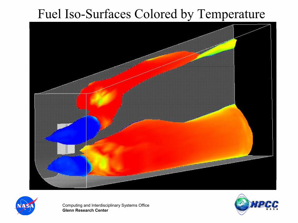
MultiDisciplinary ISTAR Simulation
• 3D Fluid (NS) Structural Simulation • Uses Overflow, Vulcan, and Ansys• Supports ISTAR Team and Oversight Team• Designed to Mature Code Coupling
Developers Kit (CCDK) Tool

Computing and Interdisciplinary Systems OfficeGlenn Research Center
ISTAR Engine Multidisciplinary Analysis
• Simulation of Approach Flow & Scram Flow for ISTAR Engine.
• Inflow Simulated with OVERFLOW; Scram Simulated with VULCAN. Structures with ANSYS
• Prelude to Aero/Thermal/Structural Simulation • CFD Solution Delivered Aug. 2001• Supports ISTAR Team and Oversight Team• Designed to Mature Code Coupling Developers Kit
(CCDK) Tool

Computing and Interdisciplinary Systems OfficeGlenn Research Center
Mach Distribution for ISTAR Engine Approach Flow

Computing and Interdisciplinary Systems OfficeGlenn Research Center
Fuel Mass Fraction in ISTAR Scram Combustor
Computing and Interdisciplinary Systems OfficeGlenn Research Center
Fuel Iso-Surfaces Colored by Temperature

Computing and Interdisciplinary Systems OfficeGlenn Research Center
Future Work: Aero/Thermal/Structural Simulation
• Thermal/Structural Simulation and Coupling with Existing Aerodynamic/Combustion Code
• Heat Fluxes for Active Cooling Requirements• Structural Deflections: Balancing Aerodynamic
and Structural Requirements• Thermal Effects on Seals

Computing and Interdisciplinary Systems OfficeGlenn Research Center
GE90 Engine Simulation
• Full Core 3D Simulation• Uses APNASA and NCC• Designed to Demonstrate Overnight
Computation Capabilities• Engineering Demonstration of 3D Code
Coupling Capability

Computing and Interdisciplinary Systems OfficeGlenn Research Center
Coupled APNASA / NCC simulations 3D flow simulation of HP turbine with APNASA
Turbofan Core Engine
3D flow simulation of complete HP compression system with APNASA
3D flow and chemistry simulation of full combustor with National Combustion Code (NCC)

Computing and Interdisciplinary Systems OfficeGlenn Research Center
Presentation Outline
• Definition of NPSS• NPSS Program Structure• Current Status of NPSS
– NPSSv1 Capabilities– Engineering Demonstrations– Planned Capabilities

Computing and Interdisciplinary Systems OfficeGlenn Research Center
V.3
�
Full Performance Envelope 2D/3D Euler, Mid Fidelity Dynamic, Mid Fidelity Geometry Access across CAD systems
CORBA Security with SecurID, Probabilistic sensitivity analysis
Information Power Grid Dynamic load balancing
Web Based Visual assembly language tools
Script assembly language, Dynamic linkable libraries, Fully interpreted elements, interactive debug
Numerical Propulsion System Simulation Roadmap
RELIABILITY
RESOURCE MGT
USABILITY
V.1
�
‘00 CY ‘06‘01 ‘02 ‘03 ‘04 ‘05
CAPABILITIES Steady-State, Transient, Low fidelity Dynamic, Reduced order & data reduction, Low Fidelity Flowpath, Geometry Design
PORTABILITY Sun, SGI, HP NT, Linux
Zooming 0D<->1D Single component, CORBA multi-ORBs, Distributed Objects
INTEROPERABILITY
Globus, LSF
V.4
�
Full Engine Performance 3D Navier-Stokes Steady State, Unsteady, Transient, High Fidelity Geometry generation
Zooming 3D<->0D/1D/2D, Multiple components. Couple Multiple disciplines: structures, thermal
V.2
�
Mid Fidelity Dynamic, Mid Fidelity Geometry Access CAD Systems
Zooming 0D<->1D/2D, 0D<-3D, Single components, CORBA Security
Information Power Grid aware load balancing, networked clusters
Visual assembly language
High-Control Formal Software Development Process with Verification and Validation for each incorporation
PERFORMANCE1000:1 reduction in execution time of 3D Turbo Machinery & Combustion simulation
Real-time ORB
Web Aware Visual assembly language tools
Distributed gathering of simulation data for monitoring, convergence, visualization
Miniaturization of hardware
24:1 reduction in 0D-1D zooming
100:1 reduction in 3D-3D coupling simulation

Computing and Interdisciplinary Systems OfficeGlenn Research Center
NPSS Version 2.0.0 Capabilities•1-D dynamic engine system operation•Aircraft installation effects•Improved thermo architecture and capability•New components, including combustion, compression, turbine expansion•Units conversion•Initial visual-based syntax stand-alone tools (graphical & command)•Input and output enhancements•Enhanced NPSS Developer Kit•Enhanced C++ converter, interactive debugger, and commands•CORBA Security•NPSS running in CORBA server mode •Common geometry interface•Initial rockets capabilities•Zooming from low to high fidelity as defined in the NPSS SRS•New user documentation: Installation Guide and Training Guide
NOTE:See NPSS SRS for detailed Version 2 requirements.

Computing and Interdisciplinary Systems OfficeGlenn Research Center
NPSS Architecture FY02 Milestones•3-D/3-D coupling of ANSYS and ADPAC wrappers incorporatedinto Development Kit.
•CORBA-based geometry services incorporated into Development Kit.
•CORBA Security services integrated with GLOBUS and incorporated into Development Kit.
•Fast probabilistic integration (FPI) deployed with Development Kit.

Computing and Interdisciplinary Systems OfficeGlenn Research Center
NPSS Wins 2001 NASA Software of the Year
Award
ALE
NPSS Wins NASA 2001 Turning Goals Into Reality
Award (TGIR)