nr 1 fire retardant wood based panels - wood products imitation melamine and wall papers (small ......
TRANSCRIPT

Vanha Porvoontie 36FIN-04600 MÄNTSÄLÄPhone: +358 (0)19 687 1103Fax: +358 (0)19 6871115E-mail: [email protected]
Elam -range of products:
-products involve a range of decoratively surfaced fire retardant wall and ceiling panels for mainly public buildings
Cement bonded particleboard consists of wood chips (30% dry weight) and portland cement (70%). No organic binders,formaldehyde or asbestos included. The boards are sanded and thickness calibrated to make them suitable for surface coating.
Elam .
Panel surfaces is usually covered with lacquered (and stained) or vaxed natural wood veneer. Other surface solutions areimitation foils, high pressure or real stone laminate or paint. Panels can be plain, perforated, slotted or grooved.
As a rule cement bonded particleboard, which is fireproof and strong, is used as core board. In locations where fireclassification requirements are not applicable, conventional wood based panels as plywood, chipboard or MDF may be usedfor core boards.
All the materials as glue, veneer and lacquer are chosen to keep the fireresistance on as high level as possible.
urved ElamForm panels, ElamTrellis, ElamInterior thin perforateddecoration panels, Perfo-Linear, Linear and Mosaic grooved panels, throughcoloured cement- bonded particleboard Anhracite, fixing accessories andspecial wood profiles.
Other Elam applications are:C
Fire retardant wood based panelsComplete system for ceilings and walls
Technical brochure
12.12.2013
Nr 1

2600 x 1200/600/300/1902400 x 1200/600/300/1901800 x 1200/600/300/190
1200 x 1200/600/300/190600 x 600/300
Dimesions, boards and surfaces
Edge types
Special perforations and striping
Installation and details.
Walls
Ceilings
Fixing accessories (metallic)
Wood mouldings
Acoustic perforation
Linear, Perfo-Linear and Mosaic
Page 2
4
19
Page3
Page
Page 6
Page 8
Page 9
Page 9
Page 14
Page 18
Page
CONTENTS:
Dimensions, boards and surfaces
Std sizes :(mm)Std thicknesses 12 and 16 mm.Other sizes and thicknesseson request.
Core boards: As a rule, strong cement bonded particleboard is used as core material, butconventional wood based panels as well, if no fire classification is required e.g.chipboard, MDF or plywood Special "marine -boards" can be used for ships.(IMO A 270, SOLAS).
Surface alternatives:Unsurfaced panels:
Painted panels:
Foil surfaced panels:
High Pressure Laminatedpanels:
Wood veneered panels:
Staining:Wax or oil treatment:
Lacquering:
All sizes, edge forms and perforations are available for raw panel as well assurfaced panel.
All commercial wood species available.
Low emission acrylate lacquering, TVOC emission less than <10 g/m h.
Colorless or colored treatment.
� 2
Up to wish and sample of customer or up to given color code.
Wood imitation melamine and wall papers (small volumes ).not available
All well-known HPL accepted.
Painting on special paper coated board. Balance film on back side.Colour stains according to e.g. NCS -code.
Broch. 1 page 2

Relevant edge coveringalternatives:
2/0 and 2/c
Edge covering alternatives :0.a.b.c.d.
(combine the code number after edge type number as shown below)Unsurfaced edgeWood or other imitation bandReal thin wood veneer, lacquered as surface2,0 mm thick wood veneer, lacquered as surface10 mm thick wood batten under surface veneer (edge type 8)
1/0, 1/a and 1/b
6/0, 6/a, 6/b and 6/c
3/0, 3/a and 3/b
7/0, 7/a and 7/b
Type 9:
11 in more detail.Removable wall panel.See page
9/0, 9/a, 9/b and 9/c
8/0 and 8/d
4/0 and 4/c
5/c
Edge types and coverings of panels and acoustic boards
Type 8:Removable ceiling panel, thickrebated wood profile under veneer.
Type 7:for
size 600 * 600 mm only.Removable ceiling panel. Recommended
Type 6:but no gap between
panels.As type 3,
Type 5:Rounded edge surfaced with2,0 mm lacquered wood veneer.
Type 4:evelled
edge (abt. 2 mm), cement grey bevelledsection with the edge 4/0.
Grooved for consealed fixing, b
Type 3:Grooved for concaled fixing with"pencil rounded arris".
Type 2:
the edge 2/0Bevelled edge (abt. 2 mm), cement greybevelled section with .
Type 1:Straight, machined edge with“pencil rounded arris".
Broch. 1 page 3

a d c
cc
b
Type S
a kk
cc
b
Type P
Acoustic perforations:
The next models are standard types, others available on request. Type S means "slotted" andP perforated (round hole). The back side of the panel can be coated with black or white fabric.
Std panel sizes are 600 x 600 ja 1200 x 600 mm:
Hole diameter Ø Bold = std diameter
Hole area %
Panel size cc Ø 6 Ø 8 Ø 10,5 Ø 12 a b c d Holes/row Rows Holes
Type mm mm % % % % mm mm mm mm pcs pcs pcs
S1a 1200 x 600 35 9,6 13,0 17,2 19,7 79 72,5 78 202 14 4 56
600 x 600 35 9,6 13,0 17,2 19,7 59 72,5 78 202 14 2 28
S1b 1200 x 600 35 8,3 11,1 14,7 16,9 79 72,5 78 202 12 4 48
600 x 600 35 8,3 11,1 14,7 16,9 59 72,5 78 202 12 2 24
S2a 1200 x 600 35 9,2 12,6 17,1 20,0 38,5 37,5 32 53 16 12 192
600 x 600 35 9,2 12,6 17,1 20,0 38,5 37,5 32 53 16 6 96
S2b 1200 x 600 35 8,1 11,1 15,0 17,5 38,5 37,5 32 53 14 12 168
600 x 600 35 8,1 11,1 15,0 17,5 38,5 37,5 32 53 14 6 84
S3a 1200 x 600 20 17,7 24,0 32,1 30 30 60 90 28 8 224
600 x 600 20 17,7 24,0 32,1 30 30 60 90 28 4 112
S3b 1200 x 600 20 12,6 17,1 22,9 26,5 30 30 60 90 20 8 160
600 x 600 20 12,6 17,1 22,9 26,5 30 30 60 90 20 4 80
S4a 1200 x 600 20 16,7 23,0 31,5 36,9 40 30 32 40 28 16 448
600 x 600 20 16,7 23,0 31,5 36,9 28 30 32 40 28 8 224
S4b 1200 x 600 20 10,7 14,8 20,3 23,7 76 30 32 40 24 12 288
600 x 600 20 10,7 14,8 20,3 23,7 64 30 32 40 24 6 144
S4c 1200 x 600 32 10,7 14,8 20,3 23,7 40 28 32 40 18 16 288
600 x 600 32 10,7 14,8 20,3 23,7 28 28 32 40 18 8 144
P1a 1200 x 600 20 6,4 11,3 19,5 25,5 30 30 20 28 58 1624
600 x 600 20 6,2 10,9 18,8 24,6 30 30 20 28 28 784
P1b 1200 x 600 20 5,7 10,2 17,5 22,9 30 30 20 28 52 1456
600 x 600 20 5,7 10,2 17,5 22,9 30 30 20 28 26 728
P1c 1200 x 600 20 5,3 9,4 16,3 21,2 30 30 20 26 52 1352
600 x 600 20 5,3 9,4 16,3 21,2 30 30 20 26 26 676
P1d 1200 x 600 20 3,1 5,6 9,6 12,6 50 50 20 20 40 800
600 x 600 20 3,1 5,6 9,6 12,6 50 50 20 20 20 400
P1e 1200 x 600 20 2,4 4,3 7,4 9,7 30 30 20 28 616
600 x 600 20 3,0 5,4 9,2 12,1 30 30 20 28 384
P2 1200 x 600 32 2,6 4,6 8,0 10,5 24 28 32 18 37 666
600 x 600 32 2,5 4,5 7,8 10,2 28 28 32 18 18 324
P3 1200 x 600 16 9,9 17,6 30,3 32 28 16 35 72 2520
600 x 600 16 9,6 17,1 29,4 28 28 16 35 35 1225
P4a 1200 x 600 16/32 5,0 8,9 15,4 20,1 24 28 16/32 1278
600 x 600 16/32 4,8 8,6 14,7 19,2 28 28 16/32 613
P4b 1200 x 600 10/20 12,4 22,1 30 30 10/20 3163
600 x 600 10/20 11,9 21,1 30 30 10/20 1513
Broch. 1 page 4

S4a
S4c
S4b
P4b
P4a
P3
S3b P2
P1dS2b
S1a
S1b
S3a
P1a
P1b
P1e
P1cS2a
77 223
Standard types: Broch. 1 page 5
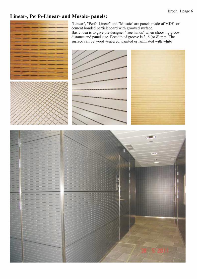
"Linear", "Perfo-Linear" and "Mosaic" are panels made of MDF- orcement bonded particleboard with grooved surface.Basic idea is to give the designer "free hands" when choosing groovdistance and panel size. Breadth of groove is 3, 6 (or 8) mm. Thesurface can be wood veneered, painted or laminated with white
Linear-, Perfo-Linear- and Mosaic- panels:Broch. 1 page 6

Perfo-Lineaari D6 K30 S60/40
Perfo-Lineaari D3 K30 S50/50 Perfo-Lineaari D3 K32 P16
Perfo-Lineaari D3 K32 P32
6 624 24
6 624,3 24,3
Or (e.g. cc30 nominal share)
Parallel joint to stripes of Linear, Perfo-Linear and Mosaic will be made with PI-3510 -profile, which ispainted to colour of core board making the panelling to look even and continuous.Crossing joint can be made with invisble tongue of plywood or painted PI-profile.
Joint parallel to stripes Joints perpendicular to stripes
Demountible ceiling panel 600x600 (edge type 7):
Linear, Mosaic or Perfo-Linear with 3 mm groove. Fixed installation:Or
Tongue of plywood 1,8x20 mm
Linear and Perfo-Lineari with 6 mm groove. Fixed installation:
Linear- and Perfo-Linear joint principles
25
600
8
5,3
5...6
52
11
Breadth of panel 599 and 299 mm (cc 600 and 300 mm)
11
65
5-6
52
PI-3510
Breadth of panel 600 and 300 mm
11
3
5-6
52
PI-3510 PI-3510
Panel sizes e.g.:
413 and 381 mm
x 600/300x 600/300x 600/300x 600/300
600 x 600/300 mm1200 mm1800 mm2400 mm2600 mmbreadth with round perforations
Stripe share e.g.:15 mm (in the egde 20 mm if edge form 3-6)20 mm30 mm40 mm50 mm
60 mm100 mm300 mmor special
Broch. 1 page 7

P2 Big 20/8 Random k 16 8/12/18Square 12x12 kk 32
Square 12x12 kk 32
"Sun"
Special striping can be made up to wishes of the client. Board material e.g. through-colored MDF.
Wave Big Wave Small
Broch. 1 page 8
can be made according to clients wishes.Special perforations
Broch. 1 page 9
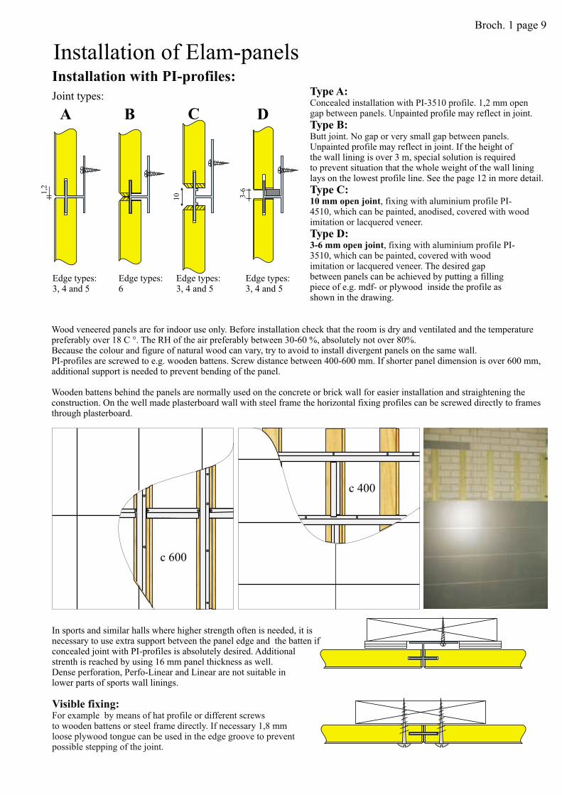
Wood veneered panels are for indoor use only. Before installation check that the room is dry and ventilated and the temperaturepreferably over 18 C °. The RH of the air preferably between 30-60 %, absolutely not over 80%.Because the colour and figure of natural wood can vary, try to avoid to install divergent panels on the same wall.
Wooden b
PI-profiles are screwed to e.g. wooden battens. Screw distance between 400-600 mm. If shorter panel dimension is over 600 mm,additional support is needed to prevent bending of the panel.
attens behind the panels are normally used on the concrete or brick wall for easier installation and straightening theconstruction. On the well made plasterboard wall with steel frame the horizontal fixing profiles can be screwed directly to framesthrough plasterboard.
Joint types:
1,2
A B
10
C
3-6
D
Installation with PI-profiles:
Visible fixing:For example by means of hat profile or different screwsto wooden battens or steel frame directly. If necessary 1,8 mmloose plywood tongue can be used in the edge groove to preventpossible stepping of the joint.
Edge types:3, 4 and 5
Edge types:3, 4 and 5
Edge types:3, 4 and 5
Edge types:6
Installation of Elam-panels
c 400
c 600
In sports and similar halls where higher strength often is needed, it isnecessary to use extra support betveen the panel edge and the batten ifconcealed joint with PI-profiles is absolutely desired. Additionalstrenth is reached by using 16 mm panel thickness as well.Dense perforation, Perfo-Linear and Linear are not suitable inlower parts of sports wall linings.
Type A:
Type B:
Type C:
Type D:
.npainted profile may reflect in joint.
npainted profile may reflect in joint. If the height ofthe wall lining is over 3 m, special solution is requiredto prevent situation that the whole weight of the wall lininglays on the lowest profile line. See the page 12 in more detail.
, PI-3510,
The desired gapbetween panels can be achieved by putting a fillingpiece of e.g. mdf- or plywood inside the profile asshown in the drawing.
10 mm o
3-6 mm o
Concealed installation with 1,2 mm opengap between panels.
Butt joint. No gap or very small gap between panels.U
, fixing with aluminium profile PI-4510, which can be painted, anodised, covered with woodimitation or lacquered veneer.
fixing with aluminium profilewhich can be painted, covered with wood
imitation or lacquered veneer.
pen joint
pen joint
PI-3510 profileU

Det S2:Gluing withpolyurethane mastic.
Det S1:EL-30 profile
Det S6
Det S9 Det S10
Det S13 a
Det S13 d
Det S13 b
Det S13 e
Det S13 c
Det S13 f
Det
S1
2a
Det
S1
2b
Det
S1
2c
Det
S1
2d
Det
S1
2e
Det
S1
2f
Det S11
Det S7 Det S8
Det S4:Fixing a starting profile withscrew or polyurethane mastic.
Det S3:Fixingwith modifiedPI-3510 profile(can be sawn at work site).
Junction to door frame: The use of wall cover board:
Det S33
Upper end of wall paneling:
Starting and ending wall paneling, examples:
Screw at the ending edge
Screw at the starting edge
Junction to floor:
Broch. 1 page 10
6
Det S18 Det S20
Det S22 Det S23
Det S25 Det S26 Det S27 Det S28
6 12
10
Det S21
6 12
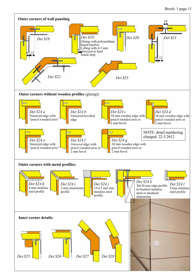
Outer corners of wall paneling
Det S19:Gluing with polyurethanebased mastics.Lifting with 4-5 mmplywood or hardboard strip.
Outer corners without wooden profiles :(gluing)
Det S24 aVeneered edge with“pencil rounded arris"
Det S24 bVeneered bevellededge
Det S24 c10 mm wooden edge with
or2 mm bevelpencil rounded arris
Det S24 d10 mm wooden edge with
or2 mm bevelpencil rounded arris
Det S24 eVeneered edge with“pencil rounded arris"
Det S24 fVeneered edge with
or2 mm bevelpencil rounded arris
Det S24 g10 mm wooden edge with
or2 mm bevelpencil rounded arris
NOTE: detail numberingchanged 22.5.2012
Outer corners with metal profiles:
Det S24 h4 mm stainlesssteel profile
Det S24 i2 mm aluminiumprofile
Det S24 j15x15 mm mmstainless steelprofile
Det S24 k30x30 mm edge profilein brushed stainlesssteel or anodisedaluminium
Det S24 l4 mm stainlesssteel profile
Inner corner details:
Broch. 1 page 11

T9
T9
T3
T3
105-6
3-4
16
3-4
J-3010
9m
m
Reuna3
Reuna6
Det S29
Det S30
Det S31
Det S32
Det S34
Det S35
Det S37
Det S36
30
30
20
Det S14
Joints with wood profiles:
Other solutions:
Edge for 6 and high wall linings:20 mm open joint:
mm o
PI-4510. Profile
The desired gap betweenpanels can be achieved byputting a filling piece of e.g.mdf- or plywood inside theprofile as shown in thedrawing.When loose band on profile isused, the edges shall havespecial groove depth to preventthe band to fall down.
20 pen joint can be made
by fixing with aluminiumprofile can bepainted, covered with woodimitation, lacquered veneer ore.g. strip of brushed stainlesssteel or laminate.
To prevent all the weight of thewall lining to lay on the lowesthorizontal fixing profile, specialarrangement is needed, if theheight of the wall lining exceeds3 m. The upper horinzontal edgeof the wall panel has to be type6 and the lower edge type 3. Thehorizontal PI-3510 profile has tobe placed very carefully to carrya part of the load and so thatthere will be no gap betweenpanels according to adjacentdrawing.
PI-profiles allows fold of about 6 . By moulding theprofile it is possible to get greater angles.12 mm thick panel can be bent to radius 10-12 m at the worksite.
o
Demountable fixing of perforatedpanel with screws.
Demountable wall panel:
J-3010modified
PI-4510modified
Demountable perforated panel can be installed between fixedpanels with screws as shown above.
At the corners of the panel 4mm black painted plywood plates areglued. Acoustic fabric (if any) is cut off in this place to ensureproper gluing. Fixing screws with small head to fit into hole. Thescrew can be black in color.
Demountable wall panels canbe made with visible screws, withwood profiles or by using edge type 9of the panel and modifying the aluminium profiles asshown in the drawing above.Note: Installation requireshighest carefulness.
4 mm blackpaintedplywood
Folded installation:
Broch. 1 page 12
4.
3.
6.
6.
5.
5.
1.
7.
1.
2.
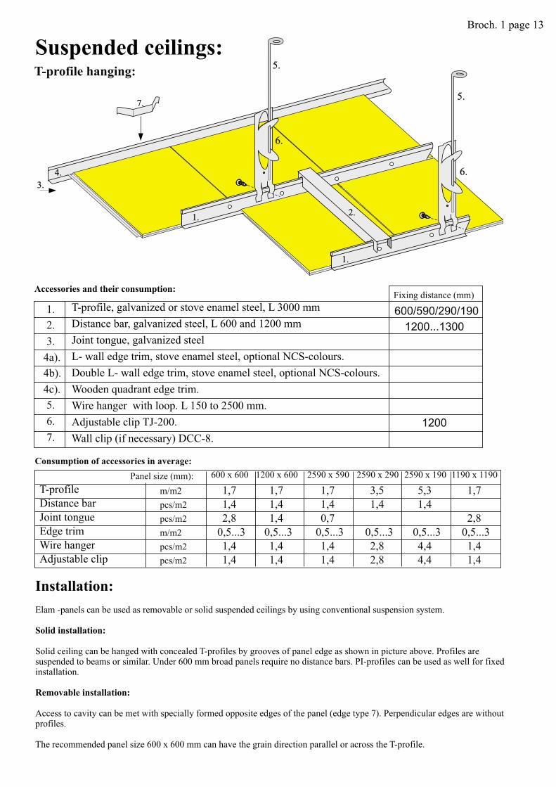
T-profile hanging:
Suspended ceilings:
Accessories and their consumption:Fixing distance (mm)
1. 600/590/290/190
2. 1200...1300
3.
4a).
4b).
4c).
5.
6. 1200
7. Wall clip (if necessary) DCC-8.
T-profile, galvanized or stove enamel steel, L 3000 mm
Distance bar, galvanized steel, L 600 and 1200 mm
Joint tongue, galvanized steel
L- wall edge trim, stove enamel steel, optional NCS-colours.
Double L- wall edge trim, stove enamel steel, optional NCS-colours.
Wooden quadrant edge trim.
Wire hanger with loop. L 150 to 2500 mm.
Adjustable clip TJ-200.
Consumption of accessories in average:
600 x 600 1200 x 600 2590 x 590 2590 x 290 2590 x 190 1190 x 1190
m/m2 1,7 1,7 1,7 3,5 5,3 1,7
pcs/m2 1,4 1,4 1,4 1,4 1,4
pcs/m2 2,8 1,4 0,7 2,8
m/m2 0,5...3 0,5...3 0,5...3 0,5...3 0,5...3 0,5...3
pcs/m2 1,4 1,4 1,4 2,8 4,4 1,4
pcs/m2 1,4 1,4 1,4 2,8 4,4 1,4
Panel size (mm):
T-profile
Distance bar
Joint tongue
Edge trim
Wire hanger
Adjustable clip
Installation:
Solid installation:
Solid ceiling can be hanged with concealed T-profiles by grooves of panel edge as shown in picture above. Profiles aresuspended to beams or similar. Under 600 mm broad panels require no distance bars. PI-profiles can be used as well for fixedinstallation.
Elam -panels can be used as removable or solid suspended ceilings by using conventional suspension system.
Access to cavity can be met with specially formed opposite edges of the panel (edge type 7). Perpendicular edges are withoutprofiles.
The recommended panel size 600 x 600 mm can have the grain direction parallel or across the T-profile.
Removable installation:
Broch. 1 page 13

By combining perforated and plain and eventually arched panels, it is possible to provide manydecorative and visual effects.
Examples of some ceiling forms:
Broch. 1 page 14
The installation can be started from the middle of the ceiling
or from the edge. Wall connection profiles are fixed with
screws c 400 mm.
Hangers for T-profile fixed to ceiling c 750-1200 mm, next to
wall 300 mm from the end of profile.
The line of panels are mounted on the profiles which are
bound together with distance bars. It's possible to glide the
whole panel line on the T-profiles.
Minumum free height above panels is abt.100 mm to ensure
access to cavity.
If the panels are made of cement bonded particleboard, the
weight of construction is abt. 15..17 kg/m2.
It is possible to install std light fittings on the T-profiles as
well.

25
11
6008
5,3
5...6
52
1:1
20
8
6008
5,3
5...6
52
DIMENSIONS for Chicago Metalic Z 151 profile
DIMENSIONS for T-24 profile
600
600
Det AK 13 a
Det AK 13 b
Wall connections:
Det AK 1
Det AK 2
L-trim
Det AK 3
Det AK 4
Double L-trim
Det AK 5
Wooden quadrant
Det AK 6
Alternative connection to side wall.Main T perpendicular to wall.
Demountable ceiling panel (edge type 7):
The order of wood grain direction to slots and edge type 7.Panel size 600 x 600 or smaller only.
Edge type 7
Edge type 7
Edge
type
1
Edge
type
1
Broch. 1 page 15

575
584
589
598
7
7
6
6
4
4
2
2
T-24 profile
T-15 profile
Fineline or Chicago 3500 profile
Dimensions without wooden edge:
Dimensions without wooden edge:
585
592
3,5
5
Demountable ceiling panel with visible profile:
Det AK 14 a
Det AK 15 a
Det AK 14 b
Det AK 15 b
Det AK 14 c
Det AK 15 c
Det AK 14 d
Det AK 15 d
Det AK 16
Broch. 1 page 16

Det AK 10 Det AK 11 Det AK 12
Det AK 18
Det AK 7 Det AK 8
Removable inspection panel:
Inspection panels can be done according to the drawingby sawing the other lap off from one edge and fix withscrews. Perforated panels can be fixed through the hole bygluing a plywood list on the rear side of the panel.
Removable inspection panel with wood battens:
T-profile will be cut 100 mm before the edge of the removable panel, and it will be replaced with U-profile.The wooden hanging battens are ready-fixed to the back side of the removable panel.
A
B
C
D
A CB
D
100
Det AK 9
Removablepanel
Over-size panels:
If the hanging distance exceeds 600 mm, the panelshave to reinforced some way to preventbending. The reinforcement can bemade for example with woodenprofiles screwed and glued behindthe panel.
Example of hanging panelsize 1190 x 1190 mm:
Installation of lighting: Panel direction in slopingceiling:
This edge down
Additional T-sectionfixed at site.
Broch. 1 page 17
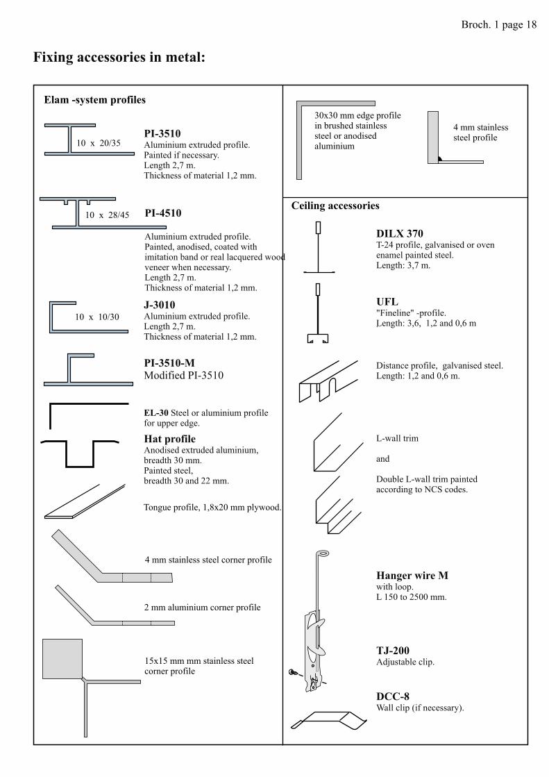
PI-3510Aluminium extruded profile.Painted if necessary.Length 2,7 m.Thickness of material 1,2 mm.
PI-3510-MModified PI-3510
PI-4510
Aluminium extruded profile.Painted, anodised, coated withimitation band or real lacquered woodveneer when necessary.Length 2,7 m.Thickness of material 1,2 mm.
J-3010Aluminium extruded profile.Length 2,7 m.Thickness of material 1,2 mm.
Hat profileAnodised extruded aluminium,breadth 30 mm.Painted steel,breadth 30 and 22 mm.
.
TJ-200Adjustable clip.
DCC-8Wall clip (if necessary).
Elam -system profiles
EL-30 Steel or aluminium profilefor upper edge.
10 x 10/30
10 x 28/45
10 x 20/35
Fixing accessories in metal:
Tongue profile, 1,8x20 mm plywood.
Hanger wire Mwith loop.L 150 to 2500 mm.
L-wall trim
and
wall trim paintedaccording to NCS codes.Double L-
Distance profile, galvanised steel.Length: 1,2 and 0,6 m.
UFL"Fineline" -profile.Length: 3,6, 1,2 and 0,6 m
DILX 370
3,7 m.
T-24 profile, galvanised or ovenenamel painted steel.Length:
Ceiling accessories
4 mm stainless steel corner profile
2 mm aluminium corner profile
15x15 mm mm stainless steelcorner profile
30x30 mm edge profilein brushed stainlesssteel or anodisedaluminium
4 mm stainlesssteel profile
Broch. 1 page 18

KLT-1Outer corner
KLT-2Outer corner withfreely chosen angle.
KLT-3Inner corner withfreely chosen angle.
KRL-1Outer corner.
KRL-2
Notched outercorner profile.
KRL-3Joint Profile.
KRL-4Outer corner withfreely chosen angle.
KRL-5Notched outer cornerwith freely chosenangle.
30
12 5
KRL-6Inner corner withfreely chosen angle.
30
12 5
KRL-7Inner notched cornerwith freely chosenangle.
Wood mouldings:KLT
KRL
-system: Fixing with
-system:
PI-aluminium profiles. Requires exact dimensioning and straightness of wallconstructions.
Fixing with screw or glue. Allows to use of sawn edges making the installation work easier.
12
x4
21
8x
42
18
x4
2
JL-1Installed on the wallpaneling.
JL-2Installed under thewall paneling.
JL-3Installed under thewall paneling withPI-profiles.
23
x4
2
JL-4Installed under thewall paneling withPI-profiles.KRL-system.PL-1
Outer corner
PL-2Bead
PL-3Corner profile
PL-4Half round jointprofile
PL-5Half-roundedge profile
PL-6Door framebead
KRL-8Edge bead
KRL-9Notched edgebead
30
8
32
x1
0
16 x 16
15 x18
23
8
18
23
8
2010
18
35
35
26
SPL-1
Suits especiallywith otherKRL-profiles.
To lift the sawn edgeof the panel to thesame level asPI-profiles.
5x
30
TL-1
30
1152
5,5
25
115
2
5,5
11
30
25 5,5
30
10
58
17
30
12 5
30
12 5
30
5 12
30
58
17
Covering profiles:
Edge profiles: Skirting profiles:
Wall end covers:
"Filling" profile:
Wal
lth
icknes
s
Broch. 1 page 19