ns-3 tutorial - dowells.net · ns-3 tutorial ns-3 project feedback: [email protected] 11...
TRANSCRIPT
ns-3 Tutorial
ns-3 projectfeedback: [email protected] January 2010
This is an ns-3 tutorial. Primary documentation for the ns-3 project is available in fourforms:• ns-3 Doxygen/Manual: Documentation of the public APIs of the simulator• Tutorial (this document)• Reference Manual: Reference Manual• ns-3 wiki
This document is written in GNU Texinfo and is to be maintained in revision control onthe ns-3 code server. Both PDF and HTML versions should be available on the server.Changes to the document should be discussed on the [email protected] mailing list.This software is free software; you can redistribute it and/or modify it under the termsof the GNU General Public License as published by the Free Software Foundation; eitherversion 2 of the License, or (at your option) any later version.This software is distributed in the hope that it will be useful, but WITHOUT ANY WAR-RANTY; without even the implied warranty of MERCHANTABILITY or FITNESS FORA PARTICULAR PURPOSE. See the GNU General Public License for more details.You should have received a copy of the GNU General Public License along with this program.If not, see http://www.gnu.org/licenses/.
i
Table of Contents
1 Introduction . . . . . . . . . . . . . . . . . . . . . . . . . . . . . . . . . . . . . 11.1 For ns-2 Users . . . . . . . . . . . . . . . . . . . . . . . . . . . . . . . . . . . . . . . . . . . . . . . . . . 11.2 Contributing . . . . . . . . . . . . . . . . . . . . . . . . . . . . . . . . . . . . . . . . . . . . . . . . . . . 21.3 Tutorial Organization . . . . . . . . . . . . . . . . . . . . . . . . . . . . . . . . . . . . . . . . . . 2
2 Resources . . . . . . . . . . . . . . . . . . . . . . . . . . . . . . . . . . . . . . . . 32.1 The Web . . . . . . . . . . . . . . . . . . . . . . . . . . . . . . . . . . . . . . . . . . . . . . . . . . . . . . . 32.2 Mercurial . . . . . . . . . . . . . . . . . . . . . . . . . . . . . . . . . . . . . . . . . . . . . . . . . . . . . . 32.3 Waf . . . . . . . . . . . . . . . . . . . . . . . . . . . . . . . . . . . . . . . . . . . . . . . . . . . . . . . . . . . . 32.4 Development Environment . . . . . . . . . . . . . . . . . . . . . . . . . . . . . . . . . . . . . 42.5 Socket Programming . . . . . . . . . . . . . . . . . . . . . . . . . . . . . . . . . . . . . . . . . . . 4
3 Getting Started . . . . . . . . . . . . . . . . . . . . . . . . . . . . . . . . . 63.1 Downloading ns-3 . . . . . . . . . . . . . . . . . . . . . . . . . . . . . . . . . . . . . . . . . . . . . . 6
3.1.1 Downloading ns-3 Using Mercurial . . . . . . . . . . . . . . . . . . . . . . . . . 63.1.2 Downloading ns-3 Using a Tarball . . . . . . . . . . . . . . . . . . . . . . . . . 9
3.2 Building ns-3 . . . . . . . . . . . . . . . . . . . . . . . . . . . . . . . . . . . . . . . . . . . . . . . . . . . 93.2.1 Building with build.py . . . . . . . . . . . . . . . . . . . . . . . . . . . . . . . . . . . . . 93.2.2 Building with Waf . . . . . . . . . . . . . . . . . . . . . . . . . . . . . . . . . . . . . . . . 10
3.3 Testing ns-3 . . . . . . . . . . . . . . . . . . . . . . . . . . . . . . . . . . . . . . . . . . . . . . . . . . . 123.4 Running a Script . . . . . . . . . . . . . . . . . . . . . . . . . . . . . . . . . . . . . . . . . . . . . . 14
4 Conceptual Overview . . . . . . . . . . . . . . . . . . . . . . . . . 154.1 Key Abstractions . . . . . . . . . . . . . . . . . . . . . . . . . . . . . . . . . . . . . . . . . . . . . 15
4.1.1 Node . . . . . . . . . . . . . . . . . . . . . . . . . . . . . . . . . . . . . . . . . . . . . . . . . . . . . 154.1.2 Application . . . . . . . . . . . . . . . . . . . . . . . . . . . . . . . . . . . . . . . . . . . . . . 154.1.3 Channel . . . . . . . . . . . . . . . . . . . . . . . . . . . . . . . . . . . . . . . . . . . . . . . . . . 164.1.4 Net Device . . . . . . . . . . . . . . . . . . . . . . . . . . . . . . . . . . . . . . . . . . . . . . . 164.1.5 Topology Helpers . . . . . . . . . . . . . . . . . . . . . . . . . . . . . . . . . . . . . . . . . 17
4.2 A First ns-3 Script . . . . . . . . . . . . . . . . . . . . . . . . . . . . . . . . . . . . . . . . . . . . 174.2.1 Boilerplate . . . . . . . . . . . . . . . . . . . . . . . . . . . . . . . . . . . . . . . . . . . . . . . 174.2.2 Module Includes . . . . . . . . . . . . . . . . . . . . . . . . . . . . . . . . . . . . . . . . . . 184.2.3 Ns3 Namespace . . . . . . . . . . . . . . . . . . . . . . . . . . . . . . . . . . . . . . . . . . 184.2.4 Logging . . . . . . . . . . . . . . . . . . . . . . . . . . . . . . . . . . . . . . . . . . . . . . . . . . 194.2.5 Main Function . . . . . . . . . . . . . . . . . . . . . . . . . . . . . . . . . . . . . . . . . . . 194.2.6 Topology Helpers . . . . . . . . . . . . . . . . . . . . . . . . . . . . . . . . . . . . . . . . . 20
4.2.6.1 NodeContainer . . . . . . . . . . . . . . . . . . . . . . . . . . . . . . . . . . . . . . 204.2.6.2 PointToPointHelper . . . . . . . . . . . . . . . . . . . . . . . . . . . . . . . . . 204.2.6.3 NetDeviceContainer . . . . . . . . . . . . . . . . . . . . . . . . . . . . . . . . . 214.2.6.4 InternetStackHelper . . . . . . . . . . . . . . . . . . . . . . . . . . . . . . . . . 224.2.6.5 Ipv4AddressHelper . . . . . . . . . . . . . . . . . . . . . . . . . . . . . . . . . . 22
4.2.7 Applications . . . . . . . . . . . . . . . . . . . . . . . . . . . . . . . . . . . . . . . . . . . . . 22
ii
4.2.7.1 UdpEchoServerHelper . . . . . . . . . . . . . . . . . . . . . . . . . . . . . . . 234.2.7.2 UdpEchoClientHelper . . . . . . . . . . . . . . . . . . . . . . . . . . . . . . . 24
4.2.8 Simulator . . . . . . . . . . . . . . . . . . . . . . . . . . . . . . . . . . . . . . . . . . . . . . . . 244.2.9 Building Your Script . . . . . . . . . . . . . . . . . . . . . . . . . . . . . . . . . . . . . 25
4.3 Ns-3 Source Code . . . . . . . . . . . . . . . . . . . . . . . . . . . . . . . . . . . . . . . . . . . . . 26
5 Tweaking ns-3 . . . . . . . . . . . . . . . . . . . . . . . . . . . . . . . . . 285.1 Using the Logging Module . . . . . . . . . . . . . . . . . . . . . . . . . . . . . . . . . . . . 28
5.1.1 Logging Overview . . . . . . . . . . . . . . . . . . . . . . . . . . . . . . . . . . . . . . . . 285.1.2 Enabling Logging . . . . . . . . . . . . . . . . . . . . . . . . . . . . . . . . . . . . . . . . 295.1.3 Adding Logging to your Code . . . . . . . . . . . . . . . . . . . . . . . . . . . . 33
5.2 Using Command Line Arguments . . . . . . . . . . . . . . . . . . . . . . . . . . . . . . 335.2.1 Overriding Default Attributes . . . . . . . . . . . . . . . . . . . . . . . . . . . . 335.2.2 Hooking Your Own Values . . . . . . . . . . . . . . . . . . . . . . . . . . . . . . . . 37
5.3 Using the Tracing System . . . . . . . . . . . . . . . . . . . . . . . . . . . . . . . . . . . . . 385.3.1 ASCII Tracing . . . . . . . . . . . . . . . . . . . . . . . . . . . . . . . . . . . . . . . . . . . 39
5.3.1.1 Parsing Ascii Traces . . . . . . . . . . . . . . . . . . . . . . . . . . . . . . . . . 405.3.2 PCAP Tracing . . . . . . . . . . . . . . . . . . . . . . . . . . . . . . . . . . . . . . . . . . . 41
5.3.2.1 Reading output with tcpdump . . . . . . . . . . . . . . . . . . . . . . . 425.3.2.2 Reading output with Wireshark . . . . . . . . . . . . . . . . . . . . . 42
6 Building Topologies . . . . . . . . . . . . . . . . . . . . . . . . . . . 436.1 Building a Bus Network Topology . . . . . . . . . . . . . . . . . . . . . . . . . . . . . 436.2 Building a Wireless Network Topology . . . . . . . . . . . . . . . . . . . . . . . . . 52
7 The Tracing System . . . . . . . . . . . . . . . . . . . . . . . . . . . 637.1 Background . . . . . . . . . . . . . . . . . . . . . . . . . . . . . . . . . . . . . . . . . . . . . . . . . . . 63
7.1.1 Blunt Instruments . . . . . . . . . . . . . . . . . . . . . . . . . . . . . . . . . . . . . . . . 637.2 Overview . . . . . . . . . . . . . . . . . . . . . . . . . . . . . . . . . . . . . . . . . . . . . . . . . . . . . 65
7.2.1 A Simple Low-Level Example . . . . . . . . . . . . . . . . . . . . . . . . . . . . . 667.2.1.1 Callbacks . . . . . . . . . . . . . . . . . . . . . . . . . . . . . . . . . . . . . . . . . . . 667.2.1.2 Example Code . . . . . . . . . . . . . . . . . . . . . . . . . . . . . . . . . . . . . . 67
7.2.2 Using the Config Subsystem to Connect to Trace Sources . . 697.2.3 How to Find and Connect Trace Sources, and Discover
Callback Signatures . . . . . . . . . . . . . . . . . . . . . . . . . . . . . . . . . . . . . . . . . 727.2.4 What Trace Sources are Available? . . . . . . . . . . . . . . . . . . . . . . . 727.2.5 What String do I use to Connect? . . . . . . . . . . . . . . . . . . . . . . . . 737.2.6 What Return Value and Formal Arguments? . . . . . . . . . . . . . . 74
7.2.6.1 Take my Word for It . . . . . . . . . . . . . . . . . . . . . . . . . . . . . . . . 757.2.6.2 The Hard Way . . . . . . . . . . . . . . . . . . . . . . . . . . . . . . . . . . . . . . 75
7.2.7 What About TracedValue? . . . . . . . . . . . . . . . . . . . . . . . . . . . . . . . 797.3 A Real Example . . . . . . . . . . . . . . . . . . . . . . . . . . . . . . . . . . . . . . . . . . . . . . 80
7.3.1 Are There Trace Sources Available? . . . . . . . . . . . . . . . . . . . . . . 807.3.2 What Script to Use? . . . . . . . . . . . . . . . . . . . . . . . . . . . . . . . . . . . . . 817.3.3 A Common Problem and Solution . . . . . . . . . . . . . . . . . . . . . . . . 817.3.4 A fifth.cc Walkthrough . . . . . . . . . . . . . . . . . . . . . . . . . . . . . . . . . . . 82
7.3.4.1 How Applications are Started and Stopped . . . . . . . . . . 84
iii
7.3.4.2 The MyApp Application . . . . . . . . . . . . . . . . . . . . . . . . . . . . . 857.3.4.3 The Trace Sinks . . . . . . . . . . . . . . . . . . . . . . . . . . . . . . . . . . . . . 877.3.4.4 The Main Program . . . . . . . . . . . . . . . . . . . . . . . . . . . . . . . . . . 88
7.3.5 Running fifth.cc . . . . . . . . . . . . . . . . . . . . . . . . . . . . . . . . . . . . . . . . . . 90
8 Closing Remarks . . . . . . . . . . . . . . . . . . . . . . . . . . . . . . 938.1 Futures . . . . . . . . . . . . . . . . . . . . . . . . . . . . . . . . . . . . . . . . . . . . . . . . . . . . . . . 938.2 Closing . . . . . . . . . . . . . . . . . . . . . . . . . . . . . . . . . . . . . . . . . . . . . . . . . . . . . . . 93
Index . . . . . . . . . . . . . . . . . . . . . . . . . . . . . . . . . . . . . . . . . . . . . . . 94
Chapter 1: Introduction 1
1 Introduction
The ns-3 simulator is a discrete-event network simulator targeted primarily for researchand educational use. The ns-3 project, started in 2006, is an open-source project developingns-3.
Primary documentation for the ns-3 project is available in four forms:• ns-3 Doxygen/Manual: Documentation of the public APIs of the simulator• Tutorial (this document)• Reference Manual: Reference Manual• ns-3 wiki
The purpose of this tutorial is to introduce new ns-3 users to the system in a structuredway. It is sometimes difficult for new users to glean essential information from detailedmanuals and to convert this information into working simulations. In this tutorial, we willbuild several example simulations, introducing and explaining key concepts and features aswe go.
As the tutorial unfolds, we will introduce the full ns-3 documentation and providepointers to source code for those interested in delving deeper into the workings of thesystem.
A few key points are worth noting at the onset:• Ns-3 is not an extension of ns-2; it is a new simulator. The two simulators are both
written in C++ but ns-3 is a new simulator that does not support the ns-2 APIs. Somemodels from ns-2 have already been ported from ns-2 to ns-3. The project will continueto maintain ns-2 while ns-3 is being built, and will study transition and integrationmechanisms.
• Ns-3 is open-source, and the project strives to maintain an open environment forresearchers to contribute and share their software.
1.1 For ns-2 Users
For those familiar with ns-2, the most visible outward change when moving to ns-3 is thechoice of scripting language. Ns-2 is scripted in OTcl and results of simulations can bevisualized using the Network Animator nam. It is not possible to run a simulation in ns-2purely from C++ (i.e., as a main() program without any OTcl). Moreover, some componentsof ns-2 are written in C++ and others in OTcl. In ns-3, the simulator is written entirely inC++, with optional Python bindings. Simulation scripts can therefore be written in C++ orin Python. The results of some simulations can be visualized by nam, but new animatorsare under development. Since ns-3 generates pcap packet trace files, other utilities can beused to analyze traces as well. In this tutorial, we will first concentrate on scripting directlyin C++ and interpreting results via trace files.
But there are similarities as well (both, for example, are based on C++ objects, andsome code from ns-2 has already been ported to ns-3). We will try to highlight differencesbetween ns-2 and ns-3 as we proceed in this tutorial.
A question that we often hear is "Should I still use ns-2 or move to ns-3?" The answeris that it depends. ns-3 does not have all of the models that ns-2 currently has, but on the
Chapter 1: Introduction 2
other hand, ns-3 does have new capabilities (such as handling multiple interfaces on nodescorrectly, use of IP addressing and more alignment with Internet protocols and designs,more detailed 802.11 models, etc.). ns-2 models can usually be ported to ns-3 (a portingguide is under development). There is active development on multiple fronts for ns-3.The ns-3 developers believe (and certain early users have proven) that ns-3 is ready foractive use, and should be an attractive alternative for users looking to start new simulationprojects.
1.2 Contributing
Ns-3 is a research and educational simulator, by and for the research community. It will relyon the ongoing contributions of the community to develop new models, debug or maintainexisting ones, and share results. There are a few policies that we hope will encourage peopleto contribute to ns-3 like they have for ns-2:• Open source licensing based on GNU GPLv2 compatibility;• wiki;• Contributed Code page, similar to ns-2’s popular Contributed Code page;• src/contrib directory (we will host your contributed code);• Open bug tracker;• Ns-3 developers will gladly help potential contributors to get started with the simulator
(please contact one of us).
We realize that if you are reading this document, contributing back to the project isprobably not your foremost concern at this point, but we want you to be aware that con-tributing is in the spirit of the project and that even the act of dropping us a note aboutyour early experience with ns-3 (e.g. "this tutorial section was not clear..."), reports ofstale documentation, etc. are much appreciated.
1.3 Tutorial Organization
The tutorial assumes that new users might initially follow a path such as the following:• Try to download and build a copy;• Try to run a few sample programs;• Look at simulation output, and try to adjust it.
As a result, we have tried to organize the tutorial along the above broad sequences ofevents.
Chapter 2: Resources 3
2 Resources
2.1 The Web
There are several important resources of which any ns-3 user must be aware. The mainweb site is located at http://www.nsnam.org and provides access to basic informationabout the ns-3 system. Detailed documentation is available through the main web siteat http://www.nsnam.org/documents.html. You can also find documents relating to thesystem architecture from this page.
There is a Wiki that complements the main ns-3 web site which you will find athttp://www.nsnam.org/wiki/. You will find user and developer FAQs there, as well astroubleshooting guides, third-party contributed code, papers, etc.
The source code may be found and browsed at http://code.nsnam.org/. There youwill find the current development tree in the repository named ns-3-dev. Past releases andexperimental repositories of the core developers may also be found there.
2.2 Mercurial
Complex software systems need some way to manage the organization and changes to theunderlying code and documentation. There are many ways to perform this feat, and youmay have heard of some of the systems that are currently used to do this. The ConcurrentVersion System (CVS) is probably the most well known.
The ns-3 project uses Mercurial as its source code management system. Althoughyou do not need to know much about Mercurial in order to complete this tutorial,we recommend becoming familiar with Mercurial and using it to access the sourcecode. Mercurial has a web site at http://www.selenic.com/mercurial/, from whichyou can get binary or source releases of this Software Configuration Management(SCM) system. Selenic (the developer of Mercurial) also provides a tutorial athttp://www.selenic.com/mercurial/wiki/index.cgi/Tutorial/, and a QuickStartguide at http://www.selenic.com/mercurial/wiki/index.cgi/QuickStart/.
You can also find vital information about using Mercurial and ns-3 on the main ns-3web site.
2.3 Waf
Once you have source code downloaded to your local system, you will need to compile thatsource to produce usable programs. Just as in the case of source code management, thereare many tools available to perform this function. Probably the most well known of thesetools is make. Along with being the most well known, make is probably the most difficult touse in a very large and highly configurable system. Because of this, many alternatives havebeen developed. Recently these systems have been developed using the Python language.
The build system Waf is used on the ns-3 project. It is one of the new generationof Python-based build systems. You will not need to understand any Python to build theexisting ns-3 system, and will only have to understand a tiny and intuitively obvious subsetof Python in order to extend the system in most cases.
For those interested in the gory details of Waf, the main web site can be found athttp://code.google.com/p/waf/.
Chapter 2: Resources 4
2.4 Development Environment
As mentioned above, scripting in ns-3 is done in C++ or Python. As of ns-3.2, most ofthe ns-3 API is available in Python, but the models are written in C++ in either case. Aworking knowledge of C++ and object-oriented concepts is assumed in this document. Wewill take some time to review some of the more advanced concepts or possibly unfamiliarlanguage features, idioms and design patterns as they appear. We don’t want this tutorialto devolve into a C++ tutorial, though, so we do expect a basic command of the language.There are an almost unimaginable number of sources of information on C++ available onthe web or in print.
If you are new to C++, you may want to find a tutorial- or cookbook-based book or website and work through at least the basic features of the language before proceeding. Forinstance, this tutorial.
The ns-3 system uses several components of the GNU “toolchain” for develop-ment. A software toolchain is the set of programming tools available in the givenenvironment. For a quick review of what is included in the GNU toolchain see,http://en.wikipedia.org/wiki/GNU_toolchain. ns-3 uses gcc, GNU binutils, and gdb.However, we do not use the GNU build system tools, neither make nor autotools. We useWaf for these functions.
Typically an ns-3 author will work in Linux or a Linux-like environment. For thoserunning under Windows, there do exist environments which simulate the Linux environmentto various degrees. The ns-3 project supports development in the Cygwin environment forthese users. See http://www.cygwin.com/ for details on downloading (MinGW is presentlynot officially supported, although some of the project maintainers to work with it). Cygwinprovides many of the popular Linux system commands. It can, however, sometimes beproblematic due to the way it actually does its emulation, and sometimes interactions withother Windows software can cause problems.
If you do use Cygwin or MinGW; and use Logitech products, we will save you quite abit of heartburn right off the bat and encourage you to take a look at the MinGW FAQ.
Search for “Logitech” and read the FAQ entry, “why does make often crash creating ash.exe.stackdump file when I try to compile my source code.” Believe it or not, the LogitechProcess Monitor insinuates itself into every DLL in the system when it is running. It cancause your Cygwin or MinGW DLLs to die in mysterious ways and often prevents debuggersfrom running. Beware of Logitech software when using Cygwin.
Another alternative to Cygwin is to install a virtual machine environment such asVMware server and install a Linux virtual machine.
2.5 Socket Programming
We will assume a basic facility with the Berkeley Sockets API in the examples used in thistutorial. If you are new to sockets, we recommend reviewing the API and some commonusage cases. For a good overview of programming TCP/IP sockets we recommend TCP/IPSockets in C.
There is an associated web site that includes source for the examples in the book, whichyou can find at: http://cs.baylor.edu/~donahoo/practical/CSockets/.

Chapter 2: Resources 5
If you understand the first four chapters of the book (or for those who do not have accessto a copy of the book, the echo clients and servers shown in the website above) you willbe in good shape to understand the tutorial. There is a similar book on Multicast Sockets,Multicast Sockets. that covers material you may need to understand if you look at themulticast examples in the distribution.
Chapter 3: Getting Started 6
3 Getting Started
3.1 Downloading ns-3
From this point forward, we are going to assume that the reader is working in Linux or aLinux emulation environment (Linux, Cygwin, etc.) and has the GNU toolchain installedand verified. We are also going to assume that you have Mercurial and Waf installed andrunning on the target system as described in the Getting Started section of the ns-3 website: http://www.nsnam.org/getting_started.html.
The ns-3 code is available in Mercurial repositories on the server http://code.nsnam.org.You can also download a tarball release at http://www.nsnam.org/releases/, or youcan work with repositories using Mercurial. We recommend using Mercurial unless there’sa good reason not to. See the end of this section for instructions on how to get a tarballrelease.
The simplest way to get started using Mercurial repositories is to use the ns-3-allinoneenvironment. This is a set of scripts that manages the downloading and building of varioussubsystems of ns-3 for you. We recommend that you begin your ns-3 adventures in thisenvironment as it can really simplify your life at this point.
3.1.1 Downloading ns-3 Using Mercurial
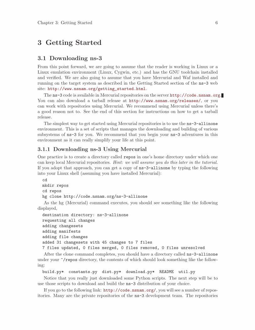
One practice is to create a directory called repos in one’s home directory under which onecan keep local Mercurial repositories. Hint: we will assume you do this later in the tutorial.If you adopt that approach, you can get a copy of ns-3-allinone by typing the followinginto your Linux shell (assuming you have installed Mercurial):cdmkdir reposcd reposhg clone http://code.nsnam.org/ns-3-allinone
As the hg (Mercurial) command executes, you should see something like the followingdisplayed,destination directory: ns-3-allinonerequesting all changesadding changesetsadding manifestsadding file changesadded 31 changesets with 45 changes to 7 files7 files updated, 0 files merged, 0 files removed, 0 files unresolved
After the clone command completes, you should have a directory called ns-3-allinoneunder your ~/repos directory, the contents of which should look something like the follow-ing:build.py* constants.py dist.py* download.py* README util.py
Notice that you really just downloaded some Python scripts. The next step will be touse those scripts to download and build the ns-3 distribution of your choice.
If you go to the following link: http://code.nsnam.org/, you will see a number of repos-itories. Many are the private repositories of the ns-3 development team. The repositories

Chapter 3: Getting Started 7
of interest to you will be prefixed with “ns-3”. Official releases of ns-3 will be numberedas ns-3.<release>.<hotfix>. For example, a second hotfix to a still hypothetical releasenine of ns-3 would be numbered as ns-3.9.2.
We have had a regression testing framework in place since the first release. For eachrelease, a set of output files that define “good behavior” are saved. These known goodoutput files are called reference traces and are associated with a given release by name. Forexample, in http://code.nsnam.org/ you will find a repository named ns-3.1 which isthe first stable release of ns-3. You will also find a separate repository named ns-3.1-ref-traces that holds the reference traces for the ns-3.1 release. It is crucial to keep thesefiles consistent if you want to do any regression testing of your repository. This is a goodidea to do at least once to verify everything has built correctly.
The current development snapshot (unreleased) of ns-3 may be found athttp://code.nsnam.org/ns-3-dev/ and the associated reference traces may be foundat http://code.nsnam.org/ns-3-dev-ref-traces/. The developers attempt to keepthese repository in consistent, working states but they are in a development area withunreleased code present, so you may want to consider staying with an official release if youdo not need newly- introduced features.
Since the release numbers are going to be changing, I will stick with the more constantns-3-dev here in the tutorial, but you can replace the string “ns-3-dev” with your choice ofrelease (e.g., ns-3.6 and ns-3.6-ref-traces) in the text below. You can find the latest versionof the code either by inspection of the repository list or by going to the “Getting Started”web page and looking for the latest release identifier.
Go ahead and change into the ns-3-allinone directory you created when you clonedthat repository. We are now going to use the download.py script to pull down the variouspieces of ns-3 you will be using.
Go ahead and type the following into your shell (remember you can substitute the nameof your chosen release number instead of ns-3-dev – like "ns-3.6" and "ns-3.6-ref-traces" if you want to work with a stable release)../download.py -n ns-3-dev -r ns-3-dev-ref-traces
Note that the default for the -n option is ns-3-dev and the default for the -r optionis ns-3-dev-ref-traces and so the above is actually redundant. We provide this exampleto illustrate how to specify alternate repositories. In order to download ns-3-dev you canactually use the defaults and simply type,./download.py
As the hg (Mercurial) command executes, you should see something like the following,## Get NS-3#
Cloning ns-3 branch=> hg clone http://code.nsnam.org/ns-3-dev ns-3-dev
requesting all changesadding changesetsadding manifestsadding file changes
Chapter 3: Getting Started 8
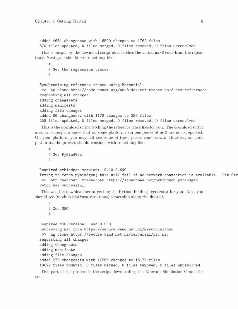
added 4634 changesets with 16500 changes to 1762 files870 files updated, 0 files merged, 0 files removed, 0 files unresolved
This is output by the download script as it fetches the actual ns-3 code from the repos-itory. Next, you should see something like,
## Get the regression traces#
Synchronizing reference traces using Mercurial.=> hg clone http://code.nsnam.org/ns-3-dev-ref-traces ns-3-dev-ref-traces
requesting all changesadding changesetsadding manifestsadding file changesadded 86 changesets with 1178 changes to 259 files208 files updated, 0 files merged, 0 files removed, 0 files unresolved
This is the download script fetching the reference trace files for you. The download scriptis smart enough to know that on some platforms various pieces of ns-3 are not supported.On your platform you may not see some of these pieces come down. However, on mostplatforms, the process should continue with something like,
## Get PyBindGen#
Required pybindgen version: 0.10.0.640Trying to fetch pybindgen; this will fail if no network connection is available. Hit Ctrl-C to skip.=> bzr checkout -rrevno:640 https://launchpad.net/pybindgen pybindgen
Fetch was successful.
This was the download script getting the Python bindings generator for you. Next youshould see (modulo platform variations) something along the lines of,
## Get NSC#
Required NSC version: nsc-0.5.0Retrieving nsc from https://secure.wand.net.nz/mercurial/nsc=> hg clone https://secure.wand.net.nz/mercurial/nsc nsc
requesting all changesadding changesetsadding manifestsadding file changesadded 273 changesets with 17565 changes to 15175 files10622 files updated, 0 files merged, 0 files removed, 0 files unresolved
This part of the process is the script downloading the Network Simulation Cradle foryou.
Chapter 3: Getting Started 9
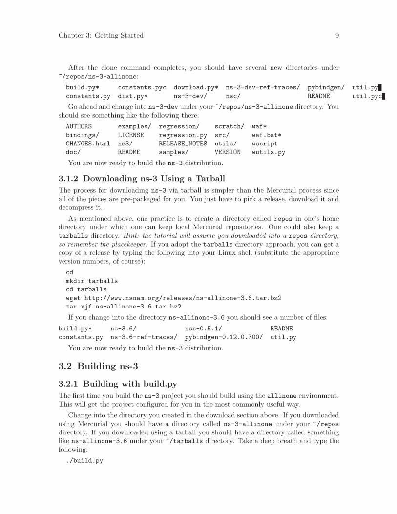
After the clone command completes, you should have several new directories under~/repos/ns-3-allinone:
build.py* constants.pyc download.py* ns-3-dev-ref-traces/ pybindgen/ util.pyconstants.py dist.py* ns-3-dev/ nsc/ README util.pyc
Go ahead and change into ns-3-dev under your ~/repos/ns-3-allinone directory. Youshould see something like the following there:
AUTHORS examples/ regression/ scratch/ waf*bindings/ LICENSE regression.py src/ waf.bat*CHANGES.html ns3/ RELEASE_NOTES utils/ wscriptdoc/ README samples/ VERSION wutils.py
You are now ready to build the ns-3 distribution.
3.1.2 Downloading ns-3 Using a Tarball
The process for downloading ns-3 via tarball is simpler than the Mercurial process sinceall of the pieces are pre-packaged for you. You just have to pick a release, download it anddecompress it.
As mentioned above, one practice is to create a directory called repos in one’s homedirectory under which one can keep local Mercurial repositories. One could also keep atarballs directory. Hint: the tutorial will assume you downloaded into a repos directory,so remember the placekeeper. If you adopt the tarballs directory approach, you can get acopy of a release by typing the following into your Linux shell (substitute the appropriateversion numbers, of course):
cdmkdir tarballscd tarballswget http://www.nsnam.org/releases/ns-allinone-3.6.tar.bz2tar xjf ns-allinone-3.6.tar.bz2
If you change into the directory ns-allinone-3.6 you should see a number of files:
build.py* ns-3.6/ nsc-0.5.1/ READMEconstants.py ns-3.6-ref-traces/ pybindgen-0.12.0.700/ util.py
You are now ready to build the ns-3 distribution.
3.2 Building ns-3
3.2.1 Building with build.py
The first time you build the ns-3 project you should build using the allinone environment.This will get the project configured for you in the most commonly useful way.
Change into the directory you created in the download section above. If you downloadedusing Mercurial you should have a directory called ns-3-allinone under your ~/reposdirectory. If you downloaded using a tarball you should have a directory called somethinglike ns-allinone-3.6 under your ~/tarballs directory. Take a deep breath and type thefollowing:
./build.py
Chapter 3: Getting Started 10
You will see lots of typical compiler output messages displayed as the build script buildsthe various pieces you downloaded. Eventually you should see the following magic words:
Waf: Leaving directory ‘/home/craigdo/repos/ns-3-allinone/ns-3-dev/build’’build’ finished successfully (2m30.586s)
Once the project has built you can say goodbye to your old friends, the ns-3-allinonescripts. You got what you needed from them and will now interact directly with Waf and wedo it in the ns-3-dev directory, not in the ns-3-allinone directory. Go ahead and changeinto the ns-3-dev directory (or the directory for the appropriate release you downloaded.
cd ns-3-dev
3.2.2 Building with Waf
We use Waf to configure and build the ns-3 project. It’s not strictly required at this point,but it will be valuable to take a slight detour and look at how to make changes to theconfiguration of the project. Probably the most useful configuration change you can makewill be to build the optimized version of the code. By default you have configured yourproject to build the debug version. Let’s tell the project to do make an optimized build.To explain to Waf that it should do optimized builds you will need to execute the followingcommand,
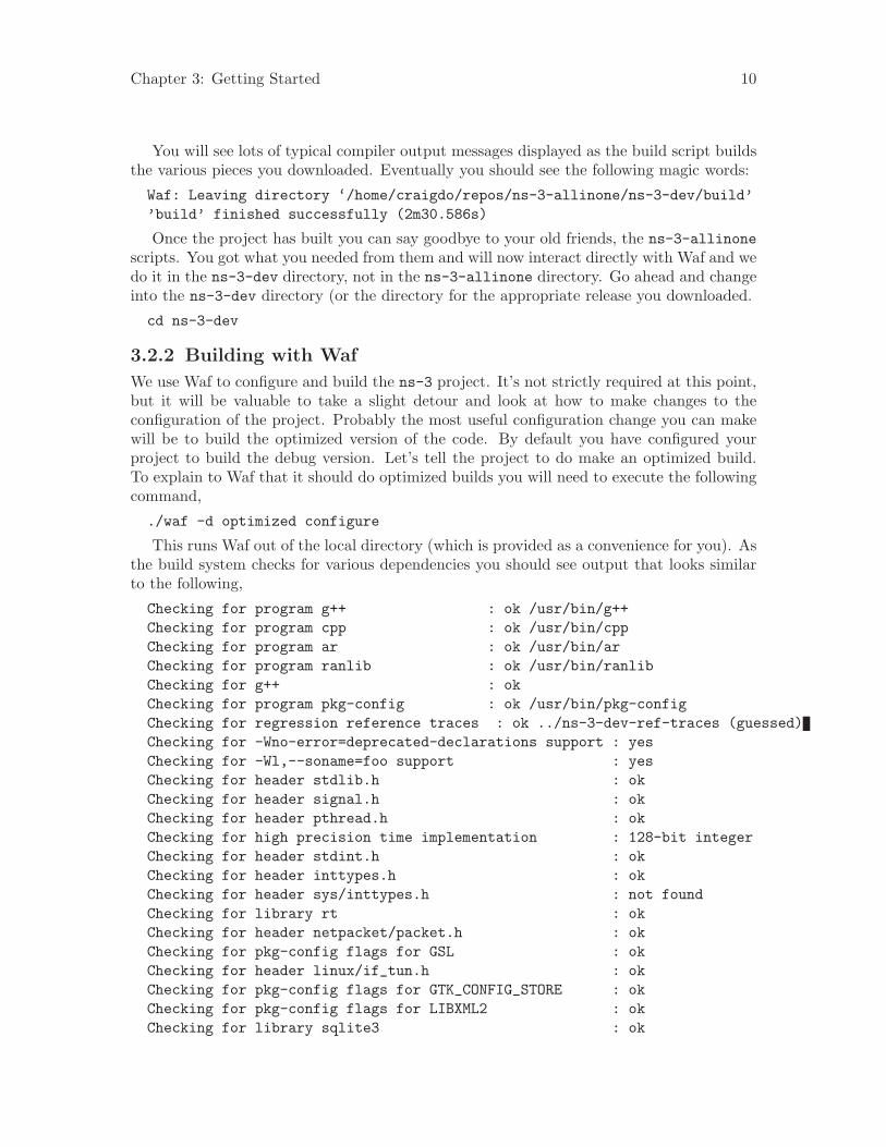
./waf -d optimized configure
This runs Waf out of the local directory (which is provided as a convenience for you). Asthe build system checks for various dependencies you should see output that looks similarto the following,
Checking for program g++ : ok /usr/bin/g++Checking for program cpp : ok /usr/bin/cppChecking for program ar : ok /usr/bin/arChecking for program ranlib : ok /usr/bin/ranlibChecking for g++ : okChecking for program pkg-config : ok /usr/bin/pkg-configChecking for regression reference traces : ok ../ns-3-dev-ref-traces (guessed)Checking for -Wno-error=deprecated-declarations support : yesChecking for -Wl,--soname=foo support : yesChecking for header stdlib.h : okChecking for header signal.h : okChecking for header pthread.h : okChecking for high precision time implementation : 128-bit integerChecking for header stdint.h : okChecking for header inttypes.h : okChecking for header sys/inttypes.h : not foundChecking for library rt : okChecking for header netpacket/packet.h : okChecking for pkg-config flags for GSL : okChecking for header linux/if_tun.h : okChecking for pkg-config flags for GTK_CONFIG_STORE : okChecking for pkg-config flags for LIBXML2 : okChecking for library sqlite3 : ok
Chapter 3: Getting Started 11
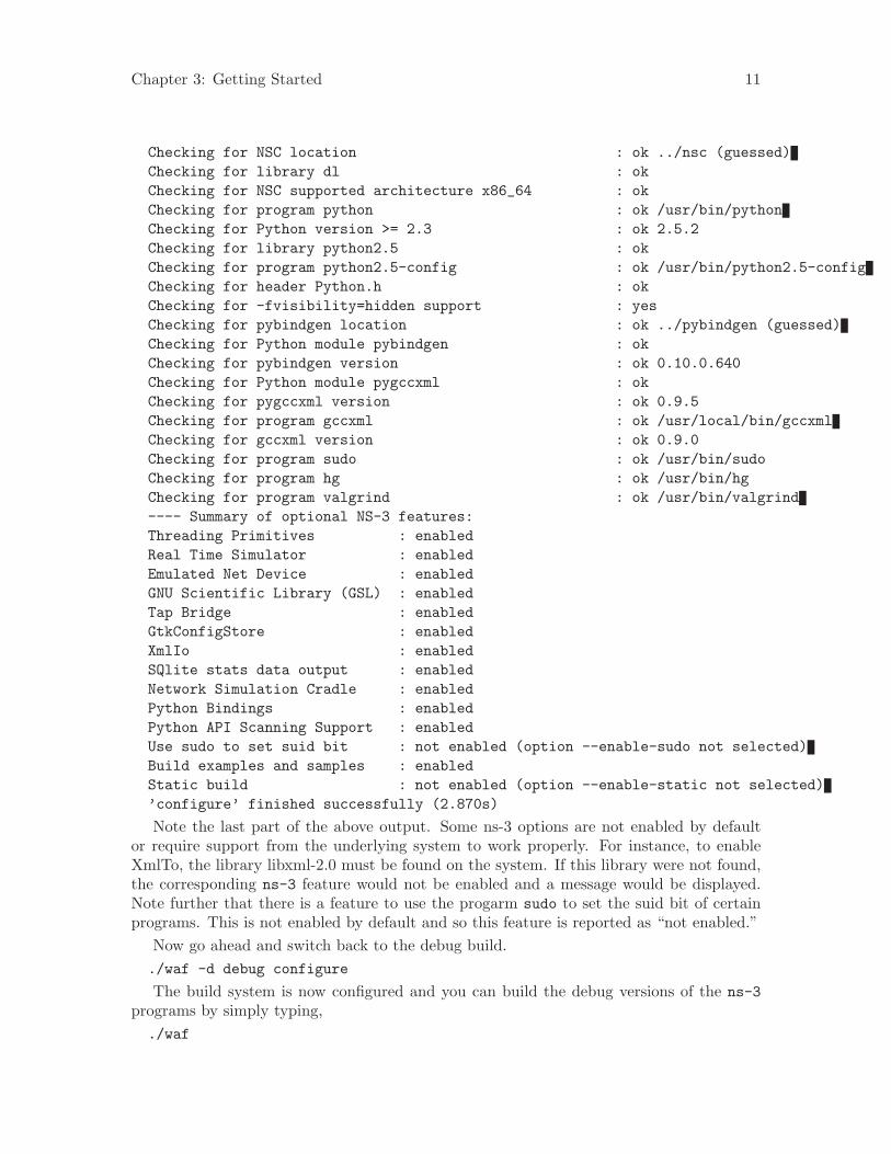
Checking for NSC location : ok ../nsc (guessed)Checking for library dl : okChecking for NSC supported architecture x86_64 : okChecking for program python : ok /usr/bin/pythonChecking for Python version >= 2.3 : ok 2.5.2Checking for library python2.5 : okChecking for program python2.5-config : ok /usr/bin/python2.5-configChecking for header Python.h : okChecking for -fvisibility=hidden support : yesChecking for pybindgen location : ok ../pybindgen (guessed)Checking for Python module pybindgen : okChecking for pybindgen version : ok 0.10.0.640Checking for Python module pygccxml : okChecking for pygccxml version : ok 0.9.5Checking for program gccxml : ok /usr/local/bin/gccxmlChecking for gccxml version : ok 0.9.0Checking for program sudo : ok /usr/bin/sudoChecking for program hg : ok /usr/bin/hgChecking for program valgrind : ok /usr/bin/valgrind---- Summary of optional NS-3 features:Threading Primitives : enabledReal Time Simulator : enabledEmulated Net Device : enabledGNU Scientific Library (GSL) : enabledTap Bridge : enabledGtkConfigStore : enabledXmlIo : enabledSQlite stats data output : enabledNetwork Simulation Cradle : enabledPython Bindings : enabledPython API Scanning Support : enabledUse sudo to set suid bit : not enabled (option --enable-sudo not selected)Build examples and samples : enabledStatic build : not enabled (option --enable-static not selected)’configure’ finished successfully (2.870s)
Note the last part of the above output. Some ns-3 options are not enabled by defaultor require support from the underlying system to work properly. For instance, to enableXmlTo, the library libxml-2.0 must be found on the system. If this library were not found,the corresponding ns-3 feature would not be enabled and a message would be displayed.Note further that there is a feature to use the progarm sudo to set the suid bit of certainprograms. This is not enabled by default and so this feature is reported as “not enabled.”
Now go ahead and switch back to the debug build../waf -d debug configure
The build system is now configured and you can build the debug versions of the ns-3programs by simply typing,./waf
Chapter 3: Getting Started 12
Some waf commands are meaningful during the build phase and some commands arevalid in the configuration phase. For example, if you wanted to use the emulation featuresof ns-3 you might want to enable setting the suid bit using sudo as described above. Thisturns out to be a configuration-time command, and so you could reconfigure using thefollowing command./waf -d debug --enable-sudo configure
If you do this, waf will have run sudo to change the socket creator programs of theemulation code to run as root. There are many other configure- and build-time optionsavailable in waf. To explore these options, type:./waf --help
We’ll use some of the testing-related commands in the next section.Okay, sorry, I made you build the ns-3 part of the system twice, but now you know how
to change the configuration and build optimized code.
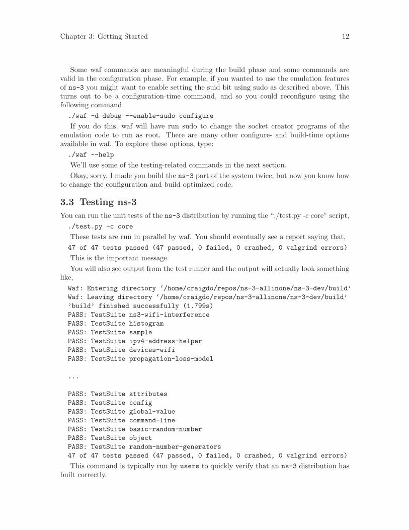
3.3 Testing ns-3
You can run the unit tests of the ns-3 distribution by running the “./test.py -c core” script,./test.py -c core
These tests are run in parallel by waf. You should eventually see a report saying that,47 of 47 tests passed (47 passed, 0 failed, 0 crashed, 0 valgrind errors)
This is the important message.You will also see output from the test runner and the output will actually look something
like,Waf: Entering directory ‘/home/craigdo/repos/ns-3-allinone/ns-3-dev/build’Waf: Leaving directory ‘/home/craigdo/repos/ns-3-allinone/ns-3-dev/build’’build’ finished successfully (1.799s)PASS: TestSuite ns3-wifi-interferencePASS: TestSuite histogramPASS: TestSuite samplePASS: TestSuite ipv4-address-helperPASS: TestSuite devices-wifiPASS: TestSuite propagation-loss-model
...
PASS: TestSuite attributesPASS: TestSuite configPASS: TestSuite global-valuePASS: TestSuite command-linePASS: TestSuite basic-random-numberPASS: TestSuite objectPASS: TestSuite random-number-generators47 of 47 tests passed (47 passed, 0 failed, 0 crashed, 0 valgrind errors)
This command is typically run by users to quickly verify that an ns-3 distribution hasbuilt correctly.
Chapter 3: Getting Started 13
You can also run our regression test suite to ensure that your distribution and toolchainhave produced binaries that generate output that is identical to known-good reference out-put files. You downloaded these reference traces to your machine during the ./download.pyprocess above. (Warning: The ns-3.2 and ns-3.3 releases do not use the ns-3-allinoneenvironment and require you to be online when you run regression tests because they dy-namically synchronize the reference traces directory with an online repository immediatelyprior to the run).
During regression testing Waf will run a number of tests that generate what we call tracefiles. The content of these trace files are compared with the reference traces. If they areidentical, the regression tests report a PASS status. If a regression test fails you will see aFAIL indication along with a pointer to the offending trace file and its associated referencetrace file along with a suggestion on diff parameters and options in order to see what hasgone awry. If the error was discovered in a pcap file, it will be useful to convert the pcapfiles to text using tcpdump prior to comparison.
Some regression tests may be SKIPped if the required support is not present.
Note that the regression tests are also run in parallel and so the messages may beinterleaved.
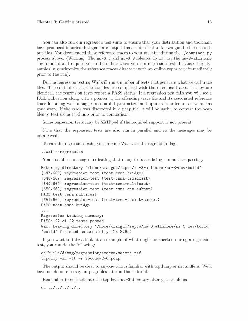
To run the regression tests, you provide Waf with the regression flag.
./waf --regression
You should see messages indicating that many tests are being run and are passing.
Entering directory ‘/home/craigdo/repos/ns-3-allinone/ns-3-dev/build’[647/669] regression-test (test-csma-bridge)[648/669] regression-test (test-csma-broadcast)[649/669] regression-test (test-csma-multicast)[650/669] regression-test (test-csma-one-subnet)PASS test-csma-multicast[651/669] regression-test (test-csma-packet-socket)PASS test-csma-bridge...Regression testing summary:PASS: 22 of 22 tests passedWaf: Leaving directory ‘/home/craigdo/repos/ns-3-allinone/ns-3-dev/build’’build’ finished successfully (25.826s)
If you want to take a look at an example of what might be checked during a regressiontest, you can do the following:
cd build/debug/regression/traces/second.reftcpdump -nn -tt -r second-2-0.pcap
The output should be clear to anyone who is familiar with tcpdump or net sniffers. We’llhave much more to say on pcap files later in this tutorial.
Remember to cd back into the top-level ns-3 directory after you are done:
cd ../../../../..
Chapter 3: Getting Started 14
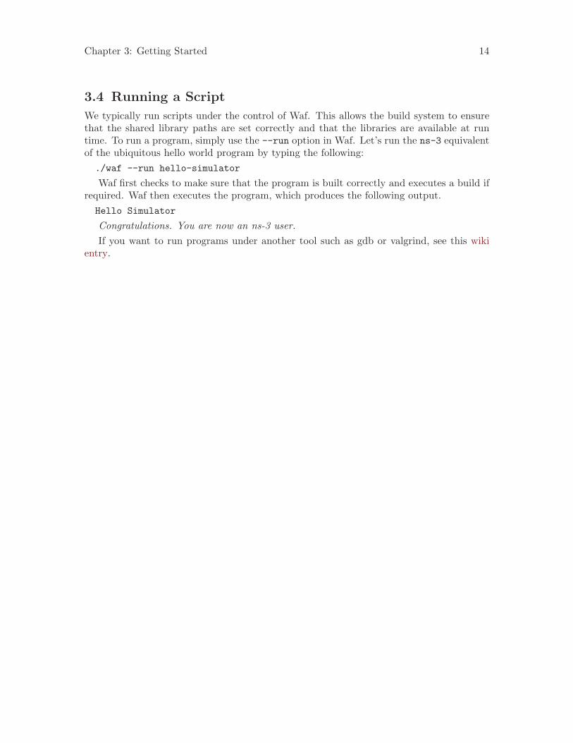
3.4 Running a Script
We typically run scripts under the control of Waf. This allows the build system to ensurethat the shared library paths are set correctly and that the libraries are available at runtime. To run a program, simply use the --run option in Waf. Let’s run the ns-3 equivalentof the ubiquitous hello world program by typing the following:./waf --run hello-simulator
Waf first checks to make sure that the program is built correctly and executes a build ifrequired. Waf then executes the program, which produces the following output.Hello Simulator
Congratulations. You are now an ns-3 user.If you want to run programs under another tool such as gdb or valgrind, see this wiki
entry.
Chapter 4: Conceptual Overview 15
4 Conceptual Overview
The first thing we need to do before actually starting to look at or write ns-3 code isto explain a few core concepts and abstractions in the system. Much of this may appeartransparently obvious to some, but we recommend taking the time to read through thissection just to ensure you are starting on a firm foundation.
4.1 Key Abstractions
In this section, we’ll review some terms that are commonly used in networking, but have aspecific meaning in ns-3.
4.1.1 Node
In Internet jargon, a computing device that connects to a network is called a host orsometimes an end system. Because ns-3 is a network simulator, not specifically an Internetsimulator, we intentionally do not use the term host since it is closely associated with theInternet and its protocols. Instead, we use a more generic term also used by other simulatorsthat originates in Graph Theory — the node.
In ns-3 the basic computing device abstraction is called the node. This abstraction isrepresented in C++ by the class Node. The Node class provides methods for managing therepresentations of computing devices in simulations.
You should think of a Node as a computer to which you will add functionality. One addsthings like applications, protocol stacks and peripheral cards with their associated driversto enable the computer to do useful work. We use the same basic model in ns-3.
4.1.2 Application
Typically, computer software is divided into two broad classes. System Software organizesvarious computer resources such as memory, processor cycles, disk, network, etc., accordingto some computing model. System software usually does not use those resources to completetasks that directly benefit a user. A user would typically run an application that acquiresand uses the resources controlled by the system software to accomplish some goal.
Often, the line of separation between system and application software is made at theprivilege level change that happens in operating system traps. In ns-3 there is no realconcept of operating system and especially no concept of privilege levels or system calls.We do, however, have the idea of an application. Just as software applications run oncomputers to perform tasks in the “real world,” ns-3 applications run on ns-3 Nodes todrive simulations in the simulated world.
In ns-3 the basic abstraction for a user program that generates some activity tobe simulated is the application. This abstraction is represented in C++ by the classApplication. The Application class provides methods for managing the representationsof our version of user-level applications in simulations. Developers are expected tospecialize the Application class in the object-oriented programming sense to create newapplications. In this tutorial, we will use specializations of class Application calledUdpEchoClientApplication and UdpEchoServerApplication. As you might expect,these applications compose a client/server application set used to generate and echosimulated network packets
Chapter 4: Conceptual Overview 16
4.1.3 Channel
In the real world, one can connect a computer to a network. Often the media over whichdata flows in these networks are called channels. When you connect your Ethernet cableto the plug in the wall, you are connecting your computer to an Ethernet communicationchannel. In the simulated world of ns-3, one connects a Node to an object representinga communication channel. Here the basic communication subnetwork abstraction is calledthe channel and is represented in C++ by the class Channel.
The Channel class provides methods for managing communication subnetwork objectsand connecting nodes to them. Channels may also be specialized by developers in the objectoriented programming sense. A Channel specialization may model something as simple asa wire. The specialized Channel can also model things as complicated as a large Ethernetswitch, or three-dimensional space full of obstructions in the case of wireless networks.
We will use specialized versions of the Channel called CsmaChannel,PointToPointChannel and WifiChannel in this tutorial. The CsmaChannel, forexample, models a version of a communication subnetwork that implements a carrier sensemultiple access communication medium. This gives us Ethernet-like functionality.
4.1.4 Net Device
It used to be the case that if you wanted to connect a computers to a network, you hadto buy a specific kind of network cable and a hardware device called (in PC terminology)a peripheral card that needed to be installed in your computer. If the peripheral cardimplemented some networking function, they were called Network Interface Cards, or NICs.Today most computers come with the network interface hardware built in and users don’tsee these building blocks.
A NIC will not work without a software driver to control the hardware. In Unix (orLinux), a piece of peripheral hardware is classified as a device. Devices are controlledusing device drivers, and network devices (NICs) are controlled using network device driverscollectively known as net devices. In Unix and Linux you refer to these net devices by namessuch as eth0.
In ns-3 the net device abstraction covers both the software driver and the simulatedhardware. A net device is “installed” in a Node in order to enable the Node to communicatewith other Nodes in the simulation via Channels. Just as in a real computer, a Node maybe connected to more than one Channel via multiple NetDevices.
The net device abstraction is represented in C++ by the class NetDevice. TheNetDevice class provides methods for managing connections to Node and Channelobjects; and may be specialized by developers in the object-oriented programming sense.We will use the several specialized versions of the NetDevice called CsmaNetDevice,PointToPointNetDevice, and WifiNetDevice in this tutorial. Just as an EthernetNIC is designed to work with an Ethernet network, the CsmaNetDevice is designed towork with a CsmaChannel; the PointToPointNetDevice is designed to work with aPointToPointChannel and a WifiNetNevice is designed to work with a WifiChannel.
Chapter 4: Conceptual Overview 17
4.1.5 Topology Helpers
In a real network, you will find host computers with added (or built-in) NICs. In ns-3 wewould say that you will find Nodes with attached NetDevices. In a large simulated networkyou will need to arrange many connections between Nodes, NetDevices and Channels.
Since connecting NetDevices to Nodes, NetDevices to Channels, assigning IP addresses,etc., are such common tasks in ns-3, we provide what we call topology helpers to makethis as easy as possible. For example, it may take many distinct ns-3 core operations tocreate a NetDevice, add a MAC address, install that net device on a Node, configure thenode’s protocol stack, and then connect the NetDevice to a Channel. Even more operationswould be required to connect multiple devices onto multipoint channels and then to connectindividual networks together into internetworks. We provide topology helper objects thatcombine those many distinct operations into an easy to use model for your convenience.
4.2 A First ns-3 Script
If you downloaded the system as was suggested above, you will have a release of ns-3 in adirectory called repos under your home directory. Change into that release directory, andyou should find a directory structure something like the following:AUTHORS doc/ README RELEASE_NOTES utils/ wscriptbindings/ examples/ regression/ samples/ VERSION wutils.pybuild/ LICENSE regression.py scratch/ waf* wutils.pycCHANGES.html ns3/ regression.pyc src/ waf.bat*
Change into the examples/tutorial directory. You should see a file named first.cclocated there. This is a script that will create a simple point-to-point link between twonodes and echo a single packet between the nodes. Let’s take a look at that script line byline, so go ahead and open first.cc in your favorite editor.
4.2.1 Boilerplate
The first line in the file is an emacs mode line. This tells emacs about the formattingconventions (coding style) we use in our source code./* -*- Mode:C++; c-file-style:’’gnu’’; indent-tabs-mode:nil; -*- */
This is always a somewhat controversial subject, so we might as well get it out of theway immediately. The ns-3 project, like most large projects, has adopted a coding style towhich all contributed code must adhere. If you want to contribute your code to the project,you will eventually have to conform to the ns-3 coding standard as described in the filedoc/codingstd.txt or shown on the project web page here.
We recommend that you, well, just get used to the look and feel of ns-3 code and adoptthis standard whenever you are working with our code. All of the development team andcontributors have done so with various amounts of grumbling. The emacs mode line abovemakes it easier to get the formatting correct if you use the emacs editor.
The ns-3 simulator is licensed using the GNU General Public License. You will see theappropriate GNU legalese at the head of every file in the ns-3 distribution. Often you willsee a copyright notice for one of the institutions involved in the ns-3 project above theGPL text and an author listed below./*
Chapter 4: Conceptual Overview 18
* This program is free software; you can redistribute it and/or modify* it under the terms of the GNU General Public License version 2 as* published by the Free Software Foundation;** This program is distributed in the hope that it will be useful,* but WITHOUT ANY WARRANTY; without even the implied warranty of* MERCHANTABILITY or FITNESS FOR A PARTICULAR PURPOSE. See the* GNU General Public License for more details.** You should have received a copy of the GNU General Public License* along with this program; if not, write to the Free Software* Foundation, Inc., 59 Temple Place, Suite 330, Boston, MA 02111-1307 USA*/
4.2.2 Module Includes
The code proper starts with a number of include statements.#include "ns3/core-module.h"#include "ns3/simulator-module.h"#include "ns3/node-module.h"#include "ns3/helper-module.h"
To help our high-level script users deal with the large number of include files present inthe system, we group includes according to relatively large modules. We provide a singleinclude file that will recursively load all of the include files used in each module. Ratherthan having to look up exactly what header you need, and possibly have to get a numberof dependencies right, we give you the ability to load a group of files at a large granularity.This is not the most efficient approach but it certainly makes writing scripts much easier.
Each of the ns-3 include files is placed in a directory called ns3 (under the build direc-tory) during the build process to help avoid include file name collisions. The ns3/core-module.h file corresponds to the ns-3 module you will find in the directory src/core inyour downloaded release distribution. If you list this directory you will find a large numberof header files. When you do a build, Waf will place public header files in an ns3 direc-tory under the appropriate build/debug or build/optimized directory depending on yourconfiguration. Waf will also automatically generate a module include file to load all of thepublic header files.
Since you are, of course, following this tutorial religiously, you will already have done a./waf -d debug configure
in order to configure the project to perform debug builds. You will also have done a./waf
to build the project. So now if you look in the directory ../../build/debug/ns3 youwill find the four module include files shown above. You can take a look at the contentsof these files and find that they do include all of the public include files in their respectivemodules.
4.2.3 Ns3 Namespace
The next line in the first.cc script is a namespace declaration.
Chapter 4: Conceptual Overview 19
using namespace ns3;
The ns-3 project is implemented in a C++ namespace called ns3. This groups all ns-3-related declarations in a scope outside the global namespace, which we hope will help withintegration with other code. The C++ using statement introduces the ns-3 namespaceinto the current (global) declarative region. This is a fancy way of saying that after thisdeclaration, you will not have to type ns3:: scope resolution operator before all of the ns-3code in order to use it. If you are unfamiliar with namespaces, please consult almost anyC++ tutorial and compare the ns3 namespace and usage here with instances of the stdnamespace and the using namespace std; statements you will often find in discussions ofcout and streams.
4.2.4 Logging
The next line of the script is the following,NS_LOG_COMPONENT_DEFINE ("FirstScriptExample");
We will use this statement as a convenient place to talk about our Doxygen documen-tation system. If you look at the project web site, ns-3 project, you will find a link to“Doxygen (ns-3-dev)” in the navigation bar. If you select this link, you will be taken to ourdocumentation page for the current development release. There is also a link to “Doxygen(stable)” that will take you to the documentation for the latest stable release of ns-3.
Along the left side, you will find a graphical representation of the structure of the docu-mentation. A good place to start is the NS-3 Modules “book” in the ns-3 navigation tree.If you expand Modules you will see a list of ns-3 module documentation. The conceptof module here ties directly into the module include files discussed above. It turns outthat the ns-3 logging subsystem is part of the core module, so go ahead and expand thatdocumentation node. Now, expand the Debugging book and then select the Logging page.
You should now be looking at the Doxygen documentation for the Logging module. Inthe list of #defines at the top of the page you will see the entry for NS_LOG_COMPONENT_DEFINE. Before jumping in, it would probably be good to look for the “Detailed Description”of the logging module to get a feel for the overall operation. You can either scroll down orselect the “More...” link under the collaboration diagram to do this.
Once you have a general idea of what is going on, go ahead and take a look at thespecific NS_LOG_COMPONENT_DEFINE documentation. I won’t duplicate the documentationhere, but to summarize, this line declares a logging component called FirstScriptExamplethat allows you to enable and disable console message logging by reference to the name.
4.2.5 Main Function
The next lines of the script you will find are,int
main (int argc, char *argv[]){
This is just the declaration of the main function of your program (script). Just as in anyC++ program, you need to define a main function that will be the first function run. Thereis nothing at all special here. Your ns-3 script is just a C++ program.
The next two lines of the script are used to enable two logging components that are builtinto the Echo Client and Echo Server applications:
Chapter 4: Conceptual Overview 20
LogComponentEnable("UdpEchoClientApplication", LOG_LEVEL_INFO);LogComponentEnable("UdpEchoServerApplication", LOG_LEVEL_INFO);
If you have read over the Logging component documentation you will have seen that thereare a number of levels of logging verbosity/detail that you can enable on each component.These two lines of code enable debug logging at the INFO level for echo clients and servers.This will result in the application printing out messages as packets are sent and receivedduring the simulation.
Now we will get directly to the business of creating a topology and running a simulation.We use the topology helper objects to make this job as easy as possible.
4.2.6 Topology Helpers
4.2.6.1 NodeContainer
The next two lines of code in our script will actually create the ns-3 Node objects that willrepresent the computers in the simulation.
NodeContainer nodes;nodes.Create (2);
Let’s find the documentation for the NodeContainer class before we continue. Anotherway to get into the documentation for a given class is via the Classes tab in the Doxygenpages. If you still have the Doxygen handy, just scroll up to the top of the page andselect the Classes tab. You should see a new set of tabs appear, one of which is ClassList. Under that tab you will see a list of all of the ns-3 classes. Scroll down, lookingfor ns3::NodeContainer. When you find the class, go ahead and select it to go to thedocumentation for the class.
You may recall that one of our key abstractions is the Node. This represents a computerto which we are going to add things like protocol stacks, applications and peripheral cards.The NodeContainer topology helper provides a convenient way to create, manage andaccess any Node objects that we create in order to run a simulation. The first line abovejust declares a NodeContainer which we call nodes. The second line calls the Createmethod on the nodes object and asks the container to create two nodes. As describedin the Doxygen, the container calls down into the ns-3 system proper to create two Nodeobjects and stores pointers to those objects internally.
The nodes as they stand in the script do nothing. The next step in constructing atopology is to connect our nodes together into a network. The simplest form of networkwe support is a single point-to-point link between two nodes. We’ll construct one of thoselinks here.
4.2.6.2 PointToPointHelper
We are constructing a point to point link, and, in a pattern which will become quite familiarto you, we use a topology helper object to do the low-level work required to put the linktogether. Recall that two of our key abstractions are the NetDevice and the Channel.In the real world, these terms correspond roughly to peripheral cards and network cables.Typically these two things are intimately tied together and one cannot expect to interchange,for example, Ethernet devices and wireless channels. Our Topology Helpers follow thisintimate coupling and therefore you will use a single PointToPointHelper to configure andconnect ns-3 PointToPointNetDevice and PointToPointChannel objects in this script.
Chapter 4: Conceptual Overview 21
The next three lines in the script are,PointToPointHelper pointToPoint;pointToPoint.SetDeviceAttribute ("DataRate", StringValue ("5Mbps"));pointToPoint.SetChannelAttribute ("Delay", StringValue ("2ms"));
The first line,PointToPointHelper pointToPoint;
instantiates a PointToPointHelper object on the stack. From a high-level perspectivethe next line,
pointToPoint.SetDeviceAttribute ("DataRate", StringValue ("5Mbps"));
tells the PointToPointHelper object to use the value “5Mbps” (five megabits per sec-ond) as the “DataRate” when it creates a PointToPointNetDevice object.
From a more detailed perspective, the string “DataRate” corresponds to what we callan Attribute of the PointToPointNetDevice. If you look at the Doxygen for classns3::PointToPointNetDevice and find the documentation for the GetTypeId method,you will find a list of Attributes defined for the device. Among these is the “DataRate”Attribute. Most user-visible ns-3 objects have similar lists of Attributes. We use thismechanism to easily configure simulations without recompiling as you will see in a followingsection.
Similar to the “DataRate” on the PointToPointNetDevice you will find a “Delay”Attribute associated with the PointToPointChannel. The final line,
pointToPoint.SetChannelAttribute ("Delay", StringValue ("2ms"));
tells the PointToPointHelper to use the value “2ms” (two milliseconds) as the value ofthe transmission delay of every point to point channel it subsequently creates.
4.2.6.3 NetDeviceContainer
At this point in the script, we have a NodeContainer that contains two nodes. We have aPointToPointHelper that is primed and ready to make PointToPointNetDevices and wirePointToPointChannel objects between them. Just as we used the NodeContainer topologyhelper object to create the Nodes for our simulation, we will ask the PointToPointHelper todo the work involved in creating, configuring and installing our devices for us. We will needto have a list of all of the NetDevice objects that are created, so we use a NetDeviceContainerto hold them just as we used a NodeContainer to hold the nodes we created. The followingtwo lines of code,
NetDeviceContainer devices;devices = pointToPoint.Install (nodes);
will finish configuring the devices and channel. The first line declares the devicecontainer mentioned above and the second does the heavy lifting. The Installmethod of the PointToPointHelper takes a NodeContainer as a parameter. Internally,a NetDeviceContainer is created. For each node in the NodeContainer (theremust be exactly two for a point-to-point link) a PointToPointNetDevice is createdand saved in the device container. A PointToPointChannel is created and thetwo PointToPointNetDevices are attached. When objects are created by thePointToPointHelper, the Attributes previously set in the helper are used to initializethe corresponding Attributes in the created objects.
Chapter 4: Conceptual Overview 22
After executing the pointToPoint.Install (nodes) call we will have two nodes, eachwith an installed point-to-point net device and a single point-to-point channel betweenthem. Both devices will be configured to transmit data at five megabits per second overthe channel which has a two millisecond transmission delay.
4.2.6.4 InternetStackHelper
We now have nodes and devices configured, but we don’t have any protocol stacks installedon our nodes. The next two lines of code will take care of that.
InternetStackHelper stack;stack.Install (nodes);
The InternetStackHelper is a topology helper that is to internet stacks what thePointToPointHelper is to point-to-point net devices. The Install method takes aNodeContainer as a parameter. When it is executed, it will install an Internet Stack(TCP, UDP, IP, etc.) on each of the nodes in the node container.
4.2.6.5 Ipv4AddressHelper
Next we need to associate the devices on our nodes with IP addresses. We provide a topologyhelper to manage the allocation of IP addresses. The only user-visible API is to set thebase IP address and network mask to use when performing the actual address allocation(which is done at a lower level inside the helper).
The next two lines of code in our example script, first.cc,
Ipv4AddressHelper address;address.SetBase ("10.1.1.0", "255.255.255.0");
declare an address helper object and tell it that it should begin allocating IP addressesfrom the network 10.1.1.0 using the mask 255.255.255.0 to define the allocatable bits. Bydefault the addresses allocated will start at one and increase monotonically, so the firstaddress allocated from this base will be 10.1.1.1, followed by 10.1.1.2, etc. The low levelns-3 system actually remembers all of the IP addresses allocated and will generate a fatalerror if you accidentally cause the same address to be generated twice (which is a very hardto debug error, by the way).
The next line of code,
Ipv4InterfaceContainer interfaces = address.Assign (devices);
performs the actual address assignment. In ns-3 we make the association between an IPaddress and a device using an Ipv4Interface object. Just as we sometimes need a list of netdevices created by a helper for future reference we sometimes need a list of Ipv4Interfaceobjects. The Ipv4InterfaceContainer provides this functionality.
Now we have a point-to-point network built, with stacks installed and IP addressesassigned. What we need at this point are applications to generate traffic.
4.2.7 Applications
Another one of the core abstractions of the ns-3 system is the Application. Inthis script we use two specializations of the core ns-3 class Application calledUdpEchoServerApplication and UdpEchoClientApplication. Just as we have in ourprevious explanations, we use helper objects to help configure and manage the underlying
Chapter 4: Conceptual Overview 23
objects. Here, we use UdpEchoServerHelper and UdpEchoClientHelper objects to makeour lives easier.
4.2.7.1 UdpEchoServerHelper
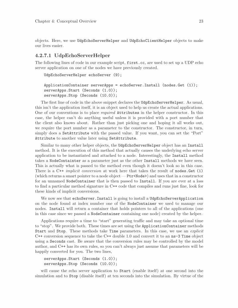
The following lines of code in our example script, first.cc, are used to set up a UDP echoserver application on one of the nodes we have previously created.
UdpEchoServerHelper echoServer (9);
ApplicationContainer serverApps = echoServer.Install (nodes.Get (1));serverApps.Start (Seconds (1.0));serverApps.Stop (Seconds (10.0));
The first line of code in the above snippet declares the UdpEchoServerHelper. As usual,this isn’t the application itself, it is an object used to help us create the actual applications.One of our conventions is to place required Attributes in the helper constructor. In thiscase, the helper can’t do anything useful unless it is provided with a port number thatthe client also knows about. Rather than just picking one and hoping it all works out,we require the port number as a parameter to the constructor. The constructor, in turn,simply does a SetAttribute with the passed value. If you want, you can set the “Port”Attribute to another value later using SetAttribute.
Similar to many other helper objects, the UdpEchoServerHelper object has an Installmethod. It is the execution of this method that actually causes the underlying echo serverapplication to be instantiated and attached to a node. Interestingly, the Install methodtakes a NodeContainter as a parameter just as the other Install methods we have seen.This is actually what is passed to the method even though it doesn’t look so in this case.There is a C++ implicit conversion at work here that takes the result of nodes.Get (1)(which returns a smart pointer to a node object — Ptr<Node>) and uses that in a constructorfor an unnamed NodeContainer that is then passed to Install. If you are ever at a lossto find a particular method signature in C++ code that compiles and runs just fine, look forthese kinds of implicit conversions.
We now see that echoServer.Install is going to install a UdpEchoServerApplicationon the node found at index number one of the NodeContainer we used to manage ournodes. Install will return a container that holds pointers to all of the applications (onein this case since we passed a NodeContainer containing one node) created by the helper.
Applications require a time to “start” generating traffic and may take an optional timeto “stop”. We provide both. These times are set using the ApplicationContainer methodsStart and Stop. These methods take Time parameters. In this case, we use an explicitC++ conversion sequence to take the C++ double 1.0 and convert it to an ns-3 Time objectusing a Seconds cast. Be aware that the conversion rules may be controlled by the modelauthor, and C++ has its own rules, so you can’t always just assume that parameters will behappily converted for you. The two lines,
serverApps.Start (Seconds (1.0));serverApps.Stop (Seconds (10.0));
will cause the echo server application to Start (enable itself) at one second into thesimulation and to Stop (disable itself) at ten seconds into the simulation. By virtue of the
Chapter 4: Conceptual Overview 24
fact that we have declared a simulation event (the application stop event) to be executedat ten seconds, the simulation will last at least ten seconds.
4.2.7.2 UdpEchoClientHelper
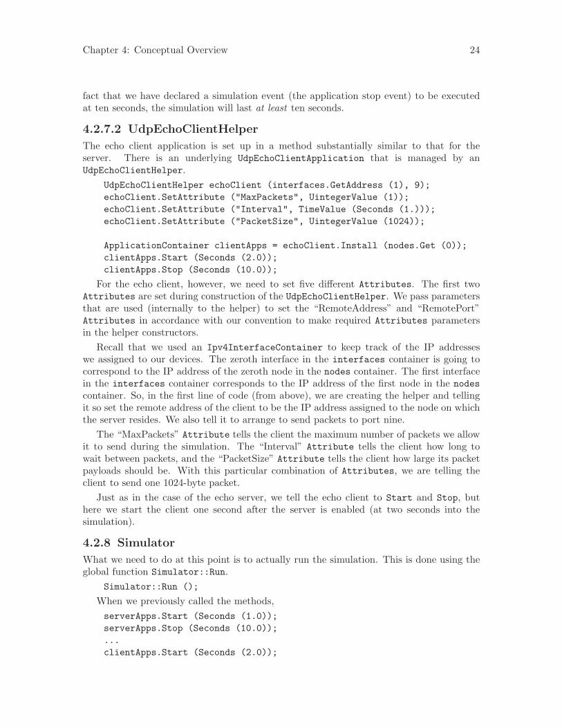
The echo client application is set up in a method substantially similar to that for theserver. There is an underlying UdpEchoClientApplication that is managed by anUdpEchoClientHelper.
UdpEchoClientHelper echoClient (interfaces.GetAddress (1), 9);echoClient.SetAttribute ("MaxPackets", UintegerValue (1));echoClient.SetAttribute ("Interval", TimeValue (Seconds (1.)));echoClient.SetAttribute ("PacketSize", UintegerValue (1024));
ApplicationContainer clientApps = echoClient.Install (nodes.Get (0));clientApps.Start (Seconds (2.0));clientApps.Stop (Seconds (10.0));
For the echo client, however, we need to set five different Attributes. The first twoAttributes are set during construction of the UdpEchoClientHelper. We pass parametersthat are used (internally to the helper) to set the “RemoteAddress” and “RemotePort”Attributes in accordance with our convention to make required Attributes parametersin the helper constructors.
Recall that we used an Ipv4InterfaceContainer to keep track of the IP addresseswe assigned to our devices. The zeroth interface in the interfaces container is going tocorrespond to the IP address of the zeroth node in the nodes container. The first interfacein the interfaces container corresponds to the IP address of the first node in the nodescontainer. So, in the first line of code (from above), we are creating the helper and tellingit so set the remote address of the client to be the IP address assigned to the node on whichthe server resides. We also tell it to arrange to send packets to port nine.
The “MaxPackets” Attribute tells the client the maximum number of packets we allowit to send during the simulation. The “Interval” Attribute tells the client how long towait between packets, and the “PacketSize” Attribute tells the client how large its packetpayloads should be. With this particular combination of Attributes, we are telling theclient to send one 1024-byte packet.
Just as in the case of the echo server, we tell the echo client to Start and Stop, buthere we start the client one second after the server is enabled (at two seconds into thesimulation).
4.2.8 Simulator
What we need to do at this point is to actually run the simulation. This is done using theglobal function Simulator::Run.
Simulator::Run ();
When we previously called the methods,serverApps.Start (Seconds (1.0));serverApps.Stop (Seconds (10.0));...clientApps.Start (Seconds (2.0));
Chapter 4: Conceptual Overview 25
clientApps.Stop (Seconds (10.0));
we actually scheduled events in the simulator at 1.0 seconds, 2.0 seconds and two eventsat 10.0 seconds. When Simulator::Run is called, the system will begin looking throughthe list of scheduled events and executing them. First it will run the event at 1.0 seconds,which will enable the echo server application (this event may, in turn, schedule many otherevents). Then it will run the event scheduled for t=2.0 seconds which will start the echoclient application. Again, this event may schedule many more events. The start eventimplementation in the echo client application will begin the data transfer phase of thesimulation by sending a packet to the server.
The act of sending the packet to the server will trigger a chain of events that will beautomatically scheduled behind the scenes and which will perform the mechanics of thepacket echo according to the various timing parameters that we have set in the script.
Eventually, since we only send one packet (recall the MaxPackets Attribute was set toone), the chain of events triggered by that single client echo request will taper off and thesimulation will go idle. Once this happens, the remaining events will be the Stop eventsfor the server and the client. When these events are executed, there are no further eventsto process and Simulator::Run returns. The simulation is then complete.
All that remains is to clean up. This is done by calling the global functionSimulator::Destroy. As the helper functions (or low level ns-3 code) executed, theyarranged it so that hooks were inserted in the simulator to destroy all of the objects thatwere created. You did not have to keep track of any of these objects yourself — all youhad to do was to call Simulator::Destroy and exit. The ns-3 system took care of thehard part for you. The remaining lines of our first ns-3 script, first.cc, do just that:
Simulator::Destroy ();return 0;
}
4.2.9 Building Your Script
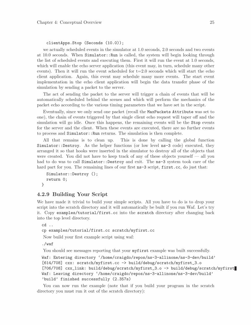
We have made it trivial to build your simple scripts. All you have to do is to drop yourscript into the scratch directory and it will automatically be built if you run Waf. Let’s tryit. Copy examples/tutorial/first.cc into the scratch directory after changing backinto the top level directory.cd ..cp examples/tutorial/first.cc scratch/myfirst.cc
Now build your first example script using waf:./waf
You should see messages reporting that your myfirst example was built successfully.Waf: Entering directory ‘/home/craigdo/repos/ns-3-allinone/ns-3-dev/build’[614/708] cxx: scratch/myfirst.cc -> build/debug/scratch/myfirst_3.o[706/708] cxx_link: build/debug/scratch/myfirst_3.o -> build/debug/scratch/myfirstWaf: Leaving directory ‘/home/craigdo/repos/ns-3-allinone/ns-3-dev/build’’build’ finished successfully (2.357s)
You can now run the example (note that if you build your program in the scratchdirectory you must run it out of the scratch directory):
Chapter 4: Conceptual Overview 26
./waf --run scratch/myfirst
You should see some output:Waf: Entering directory ‘/home/craigdo/repos/ns-3-allinone/ns-3-dev/build’Waf: Leaving directory ‘/home/craigdo/repos/ns-3-allinone/ns-3-dev/build’’build’ finished successfully (0.418s)Sent 1024 bytes to 10.1.1.2Received 1024 bytes from 10.1.1.1Received 1024 bytes from 10.1.1.2
Here you see that the build system checks to make sure that the file has been build andthen runs it. You see the logging component on the echo client indicate that it has sent one1024 byte packet to the Echo Server on 10.1.1.2. You also see the logging component on theecho server say that it has received the 1024 bytes from 10.1.1.1. The echo server silentlyechoes the packet and you see the echo client log that it has received its packet back fromthe server.
4.3 Ns-3 Source Code
Now that you have used some of the ns-3 helpers you may want to have a look at some ofthe source code that implements that functionality. The most recent code can be browsedon our web server at the following link: http://code.nsnam.org/ns-3-dev. There, youwill see the Mercurial summary page for our ns-3 development tree.
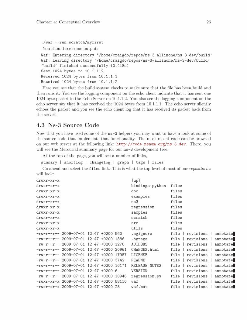
At the top of the page, you will see a number of links,summary | shortlog | changelog | graph | tags | files
Go ahead and select the files link. This is what the top-level of most of our repositorieswill look:drwxr-xr-x [up]drwxr-xr-x bindings python filesdrwxr-xr-x doc filesdrwxr-xr-x examples filesdrwxr-xr-x ns3 filesdrwxr-xr-x regression filesdrwxr-xr-x samples filesdrwxr-xr-x scratch filesdrwxr-xr-x src filesdrwxr-xr-x utils files-rw-r--r-- 2009-07-01 12:47 +0200 560 .hgignore file | revisions | annotate-rw-r--r-- 2009-07-01 12:47 +0200 1886 .hgtags file | revisions | annotate-rw-r--r-- 2009-07-01 12:47 +0200 1276 AUTHORS file | revisions | annotate-rw-r--r-- 2009-07-01 12:47 +0200 30961 CHANGES.html file | revisions | annotate-rw-r--r-- 2009-07-01 12:47 +0200 17987 LICENSE file | revisions | annotate-rw-r--r-- 2009-07-01 12:47 +0200 3742 README file | revisions | annotate-rw-r--r-- 2009-07-01 12:47 +0200 16171 RELEASE_NOTES file | revisions | annotate-rw-r--r-- 2009-07-01 12:47 +0200 6 VERSION file | revisions | annotate-rw-r--r-- 2009-07-01 12:47 +0200 10946 regression.py file | revisions | annotate-rwxr-xr-x 2009-07-01 12:47 +0200 88110 waf file | revisions | annotate-rwxr-xr-x 2009-07-01 12:47 +0200 28 waf.bat file | revisions | annotate

Chapter 4: Conceptual Overview 27
-rw-r--r-- 2009-07-01 12:47 +0200 35395 wscript file | revisions | annotate-rw-r--r-- 2009-07-01 12:47 +0200 7673 wutils.py file | revisions | annotate
Our example scripts are in the examples directory. If you click on examples you willsee a list of files. One of the files in that directory is first.cc. If you click on first.ccyou will find the code you just walked through.
The source code is mainly in the src directory. You can view source code either byclicking on the directory name or by clicking on the files link to the right of the directoryname. If you click on the src directory, you will be taken to the listing of the src subdirec-tories. If you then click on core subdirectory, you will find a list of files. The first file youwill find (as of this writing) is abort.h. If you click on the abort.h link, you will be sentto the source file for abort.h which contains useful macros for exiting scripts if abnormalconditions are detected.
The source code for the helpers we have used in this chapter can be found in thesrc/helper directory. Feel free to poke around in the directory tree to get a feel forwhat is there and the style of ns-3 programs.
Chapter 5: Tweaking ns-3 28
5 Tweaking ns-3
5.1 Using the Logging Module
We have already taken a brief look at the ns-3 logging module while going over the first.ccscript. We will now take a closer look and see what kind of use-cases the logging subsystemwas designed to cover.
5.1.1 Logging Overview
Many large systems support some kind of message logging facility, and ns-3 is not anexception. In some cases, only error messages are logged to the “operator console” (whichis typically stderr in Unix- based systems). In other systems, warning messages may beoutput as well as more detailed informational messages. In some cases, logging facilities areused to output debug messages which can quickly turn the output into a blur.
Ns-3 takes the view that all of these verbosity levels are useful and we provide a se-lectable, multi-level approach to message logging. Logging can be disabled completely, en-abled on a component-by-component basis, or enabled globally; and it provides selectableverbosity levels. The ns-3 log module provides a straightforward, relatively easy to use wayto get useful information out of your simulation.
You should understand that we do provide a general purpose mechanism — tracing —to get data out of your models which should be preferred for simulation output (see thetutorial section Using the Tracing System for more details on our tracing system). Loggingshould be preferred for debugging information, warnings, error messages, or any time youwant to easily get a quick message out of your scripts or models.
There are currently seven levels of log messages of increasing verbosity defined in thesystem.• NS LOG ERROR — Log error messages;• NS LOG WARN — Log warning messages;• NS LOG DEBUG — Log relatively rare, ad-hoc debugging messages;• NS LOG INFO — Log informational messages about program progress;• NS LOG FUNCTION — Log a message describing each function called;• NS LOG LOGIC – Log messages describing logical flow within a function;• NS LOG ALL — Log everything.
We also provide an unconditional logging level that is always displayed, irrespective oflogging levels or component selection.• NS LOG UNCOND – Log the associated message unconditionally.
Each level can be requested singly or cumulatively; and logging can be set up usinga shell environment variable (NS LOG) or by logging system function call. As was seenearlier in the tutorial, the logging system has Doxygen documentation and now would be agood time to peruse the Logging Module documentation if you have not done so.
Now that you have read the documentation in great detail, let’s use some of that knowl-edge to get some interesting information out of the scratch/myfirst.cc example scriptyou have already built.
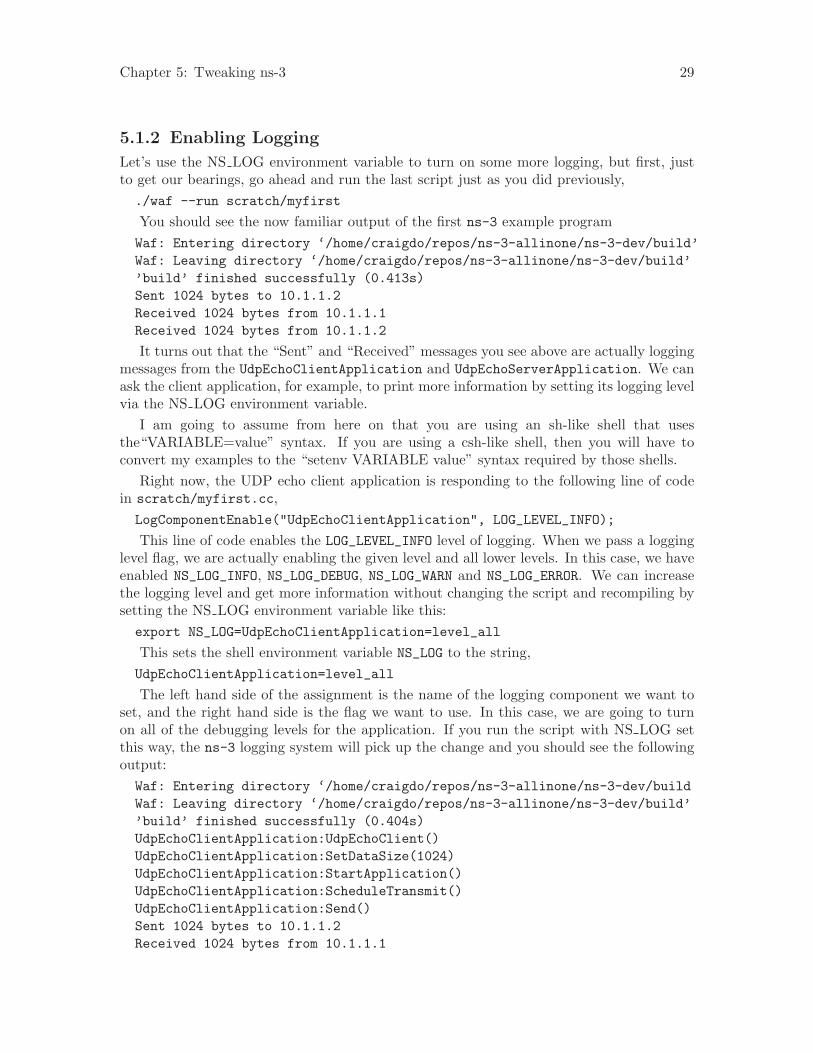
Chapter 5: Tweaking ns-3 29
5.1.2 Enabling Logging
Let’s use the NS LOG environment variable to turn on some more logging, but first, justto get our bearings, go ahead and run the last script just as you did previously,./waf --run scratch/myfirst
You should see the now familiar output of the first ns-3 example programWaf: Entering directory ‘/home/craigdo/repos/ns-3-allinone/ns-3-dev/build’Waf: Leaving directory ‘/home/craigdo/repos/ns-3-allinone/ns-3-dev/build’’build’ finished successfully (0.413s)Sent 1024 bytes to 10.1.1.2Received 1024 bytes from 10.1.1.1Received 1024 bytes from 10.1.1.2
It turns out that the “Sent” and “Received” messages you see above are actually loggingmessages from the UdpEchoClientApplication and UdpEchoServerApplication. We canask the client application, for example, to print more information by setting its logging levelvia the NS LOG environment variable.
I am going to assume from here on that you are using an sh-like shell that usesthe“VARIABLE=value” syntax. If you are using a csh-like shell, then you will have toconvert my examples to the “setenv VARIABLE value” syntax required by those shells.
Right now, the UDP echo client application is responding to the following line of codein scratch/myfirst.cc,LogComponentEnable("UdpEchoClientApplication", LOG_LEVEL_INFO);
This line of code enables the LOG_LEVEL_INFO level of logging. When we pass a logginglevel flag, we are actually enabling the given level and all lower levels. In this case, we haveenabled NS_LOG_INFO, NS_LOG_DEBUG, NS_LOG_WARN and NS_LOG_ERROR. We can increasethe logging level and get more information without changing the script and recompiling bysetting the NS LOG environment variable like this:export NS_LOG=UdpEchoClientApplication=level_all
This sets the shell environment variable NS_LOG to the string,UdpEchoClientApplication=level_all
The left hand side of the assignment is the name of the logging component we want toset, and the right hand side is the flag we want to use. In this case, we are going to turnon all of the debugging levels for the application. If you run the script with NS LOG setthis way, the ns-3 logging system will pick up the change and you should see the followingoutput:Waf: Entering directory ‘/home/craigdo/repos/ns-3-allinone/ns-3-dev/buildWaf: Leaving directory ‘/home/craigdo/repos/ns-3-allinone/ns-3-dev/build’’build’ finished successfully (0.404s)UdpEchoClientApplication:UdpEchoClient()UdpEchoClientApplication:SetDataSize(1024)UdpEchoClientApplication:StartApplication()UdpEchoClientApplication:ScheduleTransmit()UdpEchoClientApplication:Send()Sent 1024 bytes to 10.1.1.2Received 1024 bytes from 10.1.1.1
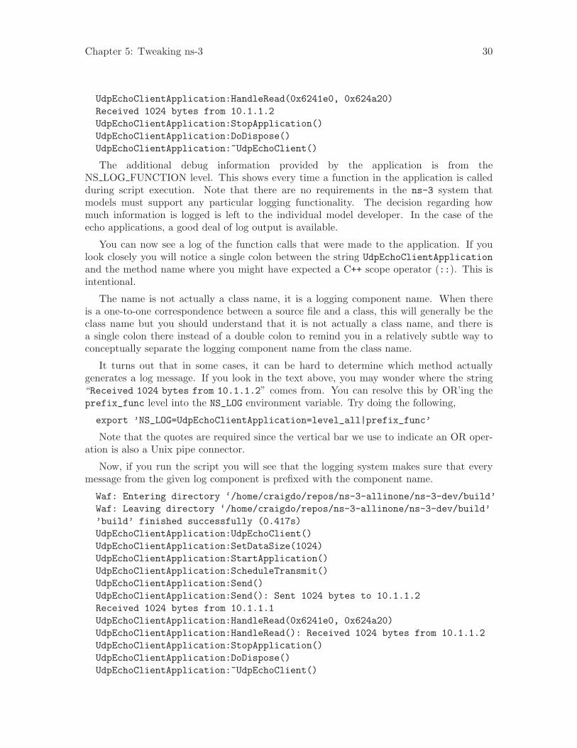
Chapter 5: Tweaking ns-3 30
UdpEchoClientApplication:HandleRead(0x6241e0, 0x624a20)Received 1024 bytes from 10.1.1.2UdpEchoClientApplication:StopApplication()UdpEchoClientApplication:DoDispose()UdpEchoClientApplication:~UdpEchoClient()
The additional debug information provided by the application is from theNS LOG FUNCTION level. This shows every time a function in the application is calledduring script execution. Note that there are no requirements in the ns-3 system thatmodels must support any particular logging functionality. The decision regarding howmuch information is logged is left to the individual model developer. In the case of theecho applications, a good deal of log output is available.
You can now see a log of the function calls that were made to the application. If youlook closely you will notice a single colon between the string UdpEchoClientApplicationand the method name where you might have expected a C++ scope operator (::). This isintentional.
The name is not actually a class name, it is a logging component name. When thereis a one-to-one correspondence between a source file and a class, this will generally be theclass name but you should understand that it is not actually a class name, and there isa single colon there instead of a double colon to remind you in a relatively subtle way toconceptually separate the logging component name from the class name.
It turns out that in some cases, it can be hard to determine which method actuallygenerates a log message. If you look in the text above, you may wonder where the string“Received 1024 bytes from 10.1.1.2” comes from. You can resolve this by OR’ing theprefix_func level into the NS_LOG environment variable. Try doing the following,
export ’NS_LOG=UdpEchoClientApplication=level_all|prefix_func’
Note that the quotes are required since the vertical bar we use to indicate an OR oper-ation is also a Unix pipe connector.
Now, if you run the script you will see that the logging system makes sure that everymessage from the given log component is prefixed with the component name.
Waf: Entering directory ‘/home/craigdo/repos/ns-3-allinone/ns-3-dev/build’Waf: Leaving directory ‘/home/craigdo/repos/ns-3-allinone/ns-3-dev/build’’build’ finished successfully (0.417s)UdpEchoClientApplication:UdpEchoClient()UdpEchoClientApplication:SetDataSize(1024)UdpEchoClientApplication:StartApplication()UdpEchoClientApplication:ScheduleTransmit()UdpEchoClientApplication:Send()UdpEchoClientApplication:Send(): Sent 1024 bytes to 10.1.1.2Received 1024 bytes from 10.1.1.1UdpEchoClientApplication:HandleRead(0x6241e0, 0x624a20)UdpEchoClientApplication:HandleRead(): Received 1024 bytes from 10.1.1.2UdpEchoClientApplication:StopApplication()UdpEchoClientApplication:DoDispose()UdpEchoClientApplication:~UdpEchoClient()
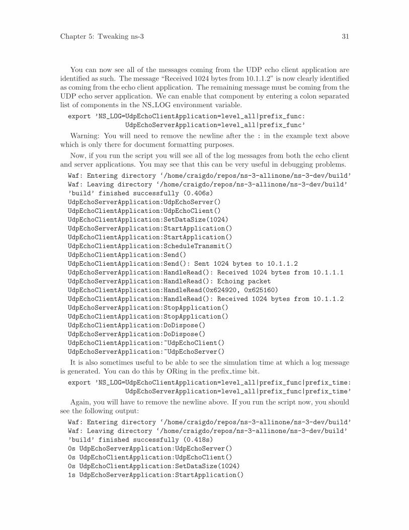
Chapter 5: Tweaking ns-3 31
You can now see all of the messages coming from the UDP echo client application areidentified as such. The message “Received 1024 bytes from 10.1.1.2” is now clearly identifiedas coming from the echo client application. The remaining message must be coming from theUDP echo server application. We can enable that component by entering a colon separatedlist of components in the NS LOG environment variable.export ’NS_LOG=UdpEchoClientApplication=level_all|prefix_func:
UdpEchoServerApplication=level_all|prefix_func’
Warning: You will need to remove the newline after the : in the example text abovewhich is only there for document formatting purposes.
Now, if you run the script you will see all of the log messages from both the echo clientand server applications. You may see that this can be very useful in debugging problems.Waf: Entering directory ‘/home/craigdo/repos/ns-3-allinone/ns-3-dev/build’Waf: Leaving directory ‘/home/craigdo/repos/ns-3-allinone/ns-3-dev/build’’build’ finished successfully (0.406s)UdpEchoServerApplication:UdpEchoServer()UdpEchoClientApplication:UdpEchoClient()UdpEchoClientApplication:SetDataSize(1024)UdpEchoServerApplication:StartApplication()UdpEchoClientApplication:StartApplication()UdpEchoClientApplication:ScheduleTransmit()UdpEchoClientApplication:Send()UdpEchoClientApplication:Send(): Sent 1024 bytes to 10.1.1.2UdpEchoServerApplication:HandleRead(): Received 1024 bytes from 10.1.1.1UdpEchoServerApplication:HandleRead(): Echoing packetUdpEchoClientApplication:HandleRead(0x624920, 0x625160)UdpEchoClientApplication:HandleRead(): Received 1024 bytes from 10.1.1.2UdpEchoServerApplication:StopApplication()UdpEchoClientApplication:StopApplication()UdpEchoClientApplication:DoDispose()UdpEchoServerApplication:DoDispose()UdpEchoClientApplication:~UdpEchoClient()UdpEchoServerApplication:~UdpEchoServer()
It is also sometimes useful to be able to see the simulation time at which a log messageis generated. You can do this by ORing in the prefix time bit.export ’NS_LOG=UdpEchoClientApplication=level_all|prefix_func|prefix_time:
UdpEchoServerApplication=level_all|prefix_func|prefix_time’
Again, you will have to remove the newline above. If you run the script now, you shouldsee the following output:Waf: Entering directory ‘/home/craigdo/repos/ns-3-allinone/ns-3-dev/build’Waf: Leaving directory ‘/home/craigdo/repos/ns-3-allinone/ns-3-dev/build’’build’ finished successfully (0.418s)0s UdpEchoServerApplication:UdpEchoServer()0s UdpEchoClientApplication:UdpEchoClient()0s UdpEchoClientApplication:SetDataSize(1024)1s UdpEchoServerApplication:StartApplication()
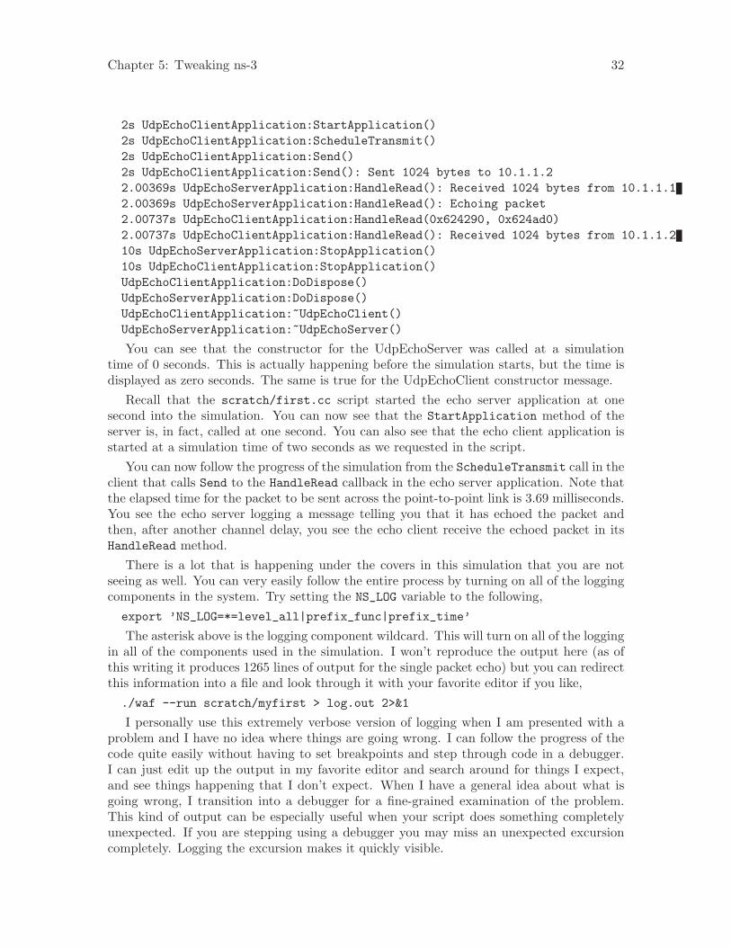
Chapter 5: Tweaking ns-3 32
2s UdpEchoClientApplication:StartApplication()2s UdpEchoClientApplication:ScheduleTransmit()2s UdpEchoClientApplication:Send()2s UdpEchoClientApplication:Send(): Sent 1024 bytes to 10.1.1.22.00369s UdpEchoServerApplication:HandleRead(): Received 1024 bytes from 10.1.1.12.00369s UdpEchoServerApplication:HandleRead(): Echoing packet2.00737s UdpEchoClientApplication:HandleRead(0x624290, 0x624ad0)2.00737s UdpEchoClientApplication:HandleRead(): Received 1024 bytes from 10.1.1.210s UdpEchoServerApplication:StopApplication()10s UdpEchoClientApplication:StopApplication()UdpEchoClientApplication:DoDispose()UdpEchoServerApplication:DoDispose()UdpEchoClientApplication:~UdpEchoClient()UdpEchoServerApplication:~UdpEchoServer()
You can see that the constructor for the UdpEchoServer was called at a simulationtime of 0 seconds. This is actually happening before the simulation starts, but the time isdisplayed as zero seconds. The same is true for the UdpEchoClient constructor message.
Recall that the scratch/first.cc script started the echo server application at onesecond into the simulation. You can now see that the StartApplication method of theserver is, in fact, called at one second. You can also see that the echo client application isstarted at a simulation time of two seconds as we requested in the script.
You can now follow the progress of the simulation from the ScheduleTransmit call in theclient that calls Send to the HandleRead callback in the echo server application. Note thatthe elapsed time for the packet to be sent across the point-to-point link is 3.69 milliseconds.You see the echo server logging a message telling you that it has echoed the packet andthen, after another channel delay, you see the echo client receive the echoed packet in itsHandleRead method.
There is a lot that is happening under the covers in this simulation that you are notseeing as well. You can very easily follow the entire process by turning on all of the loggingcomponents in the system. Try setting the NS_LOG variable to the following,export ’NS_LOG=*=level_all|prefix_func|prefix_time’
The asterisk above is the logging component wildcard. This will turn on all of the loggingin all of the components used in the simulation. I won’t reproduce the output here (as ofthis writing it produces 1265 lines of output for the single packet echo) but you can redirectthis information into a file and look through it with your favorite editor if you like,./waf --run scratch/myfirst > log.out 2>&1
I personally use this extremely verbose version of logging when I am presented with aproblem and I have no idea where things are going wrong. I can follow the progress of thecode quite easily without having to set breakpoints and step through code in a debugger.I can just edit up the output in my favorite editor and search around for things I expect,and see things happening that I don’t expect. When I have a general idea about what isgoing wrong, I transition into a debugger for a fine-grained examination of the problem.This kind of output can be especially useful when your script does something completelyunexpected. If you are stepping using a debugger you may miss an unexpected excursioncompletely. Logging the excursion makes it quickly visible.
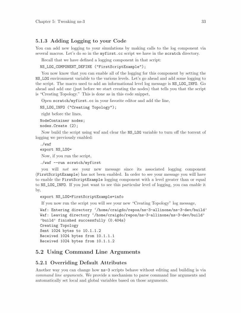
Chapter 5: Tweaking ns-3 33
5.1.3 Adding Logging to your Code
You can add new logging to your simulations by making calls to the log component viaseveral macros. Let’s do so in the myfirst.cc script we have in the scratch directory.
Recall that we have defined a logging component in that script:
NS_LOG_COMPONENT_DEFINE ("FirstScriptExample");
You now know that you can enable all of the logging for this component by setting theNS_LOG environment variable to the various levels. Let’s go ahead and add some logging tothe script. The macro used to add an informational level log message is NS_LOG_INFO. Goahead and add one (just before we start creating the nodes) that tells you that the scriptis “Creating Topology.” This is done as in this code snippet,
Open scratch/myfirst.cc in your favorite editor and add the line,
NS_LOG_INFO ("Creating Topology");
right before the lines,
NodeContainer nodes;nodes.Create (2);
Now build the script using waf and clear the NS_LOG variable to turn off the torrent oflogging we previously enabled:
./wafexport NS_LOG=
Now, if you run the script,
./waf --run scratch/myfirst
you will not see your new message since its associated logging component(FirstScriptExample) has not been enabled. In order to see your message you will haveto enable the FirstScriptExample logging component with a level greater than or equalto NS_LOG_INFO. If you just want to see this particular level of logging, you can enable itby,
export NS_LOG=FirstScriptExample=info
If you now run the script you will see your new “Creating Topology” log message,
Waf: Entering directory ‘/home/craigdo/repos/ns-3-allinone/ns-3-dev/build’Waf: Leaving directory ‘/home/craigdo/repos/ns-3-allinone/ns-3-dev/build’’build’ finished successfully (0.404s)Creating TopologySent 1024 bytes to 10.1.1.2Received 1024 bytes from 10.1.1.1Received 1024 bytes from 10.1.1.2
5.2 Using Command Line Arguments
5.2.1 Overriding Default Attributes
Another way you can change how ns-3 scripts behave without editing and building is viacommand line arguments. We provide a mechanism to parse command line arguments andautomatically set local and global variables based on those arguments.
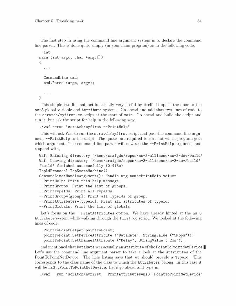
Chapter 5: Tweaking ns-3 34
The first step in using the command line argument system is to declare the commandline parser. This is done quite simply (in your main program) as in the following code,
intmain (int argc, char *argv[]){
...
CommandLine cmd;cmd.Parse (argc, argv);
...}
This simple two line snippet is actually very useful by itself. It opens the door to thens-3 global variable and Attribute systems. Go ahead and add that two lines of code tothe scratch/myfirst.cc script at the start of main. Go ahead and build the script andrun it, but ask the script for help in the following way,
./waf --run "scratch/myfirst --PrintHelp"
This will ask Waf to run the scratch/myfirst script and pass the command line argu-ment --PrintHelp to the script. The quotes are required to sort out which program getswhich argument. The command line parser will now see the --PrintHelp argument andrespond with,
Waf: Entering directory ‘/home/craigdo/repos/ns-3-allinone/ns-3-dev/build’Waf: Leaving directory ‘/home/craigdo/repos/ns-3-allinone/ns-3-dev/build’’build’ finished successfully (0.413s)TcpL4Protocol:TcpStateMachine()CommandLine:HandleArgument(): Handle arg name=PrintHelp value=--PrintHelp: Print this help message.--PrintGroups: Print the list of groups.--PrintTypeIds: Print all TypeIds.--PrintGroup=[group]: Print all TypeIds of group.--PrintAttributes=[typeid]: Print all attributes of typeid.--PrintGlobals: Print the list of globals.
Let’s focus on the --PrintAttributes option. We have already hinted at the ns-3Attribute system while walking through the first.cc script. We looked at the followinglines of code,
PointToPointHelper pointToPoint;pointToPoint.SetDeviceAttribute ("DataRate", StringValue ("5Mbps"));pointToPoint.SetChannelAttribute ("Delay", StringValue ("2ms"));
and mentioned that DataRate was actually an Attribute of the PointToPointNetDevice.Let’s use the command line argument parser to take a look at the Attributes of thePointToPointNetDevice. The help listing says that we should provide a TypeId. Thiscorresponds to the class name of the class to which the Attributes belong. In this case itwill be ns3::PointToPointNetDevice. Let’s go ahead and type in,
./waf --run "scratch/myfirst --PrintAttributes=ns3::PointToPointNetDevice"

Chapter 5: Tweaking ns-3 35
The system will print out all of the Attributes of this kind of net device. Among theAttributes you will see listed is,
--ns3::PointToPointNetDevice::DataRate=[32768bps]:The default data rate for point to point links
This is the default value that will be used when a PointToPointNetDevice iscreated in the system. We overrode this default with the Attribute setting in thePointToPointHelper above. Let’s use the default values for the point-to-point devicesand channels by deleting the SetDeviceAttribute call and the SetChannelAttributecall from the myfirst.cc we have in the scratch directory.
Your script should now just declare the PointToPointHelper and not do any set oper-ations as in the following example,
...
NodeContainer nodes;nodes.Create (2);
PointToPointHelper pointToPoint;
NetDeviceContainer devices;devices = pointToPoint.Install (nodes);
...
Go ahead and build the new script with Waf (./waf) and let’s go back and enable somelogging from the UDP echo server application and turn on the time prefix.
export ’NS_LOG=UdpEchoServerApplication=level_all|prefix_time’
If you run the script, you should now see the following output,
Waf: Entering directory ‘/home/craigdo/repos/ns-3-allinone/ns-3-dev/build’Waf: Leaving directory ‘/home/craigdo/repos/ns-3-allinone/ns-3-dev/build’’build’ finished successfully (0.405s)0s UdpEchoServerApplication:UdpEchoServer()1s UdpEchoServerApplication:StartApplication()Sent 1024 bytes to 10.1.1.22.25732s Received 1024 bytes from 10.1.1.12.25732s Echoing packetReceived 1024 bytes from 10.1.1.210s UdpEchoServerApplication:StopApplication()UdpEchoServerApplication:DoDispose()UdpEchoServerApplication:~UdpEchoServer()
Recall that the last time we looked at the simulation time at which the packet wasreceived by the echo server, it was at 2.00369 seconds.
2.00369s UdpEchoServerApplication:HandleRead(): Received 1024 bytes from 10.1.1.1
Now it is receiving the packet at 2.25732 seconds. This is because we just dropped thedata rate of the PointToPointNetDevice down to its default of 32768 bits per second fromfive megabits per second.
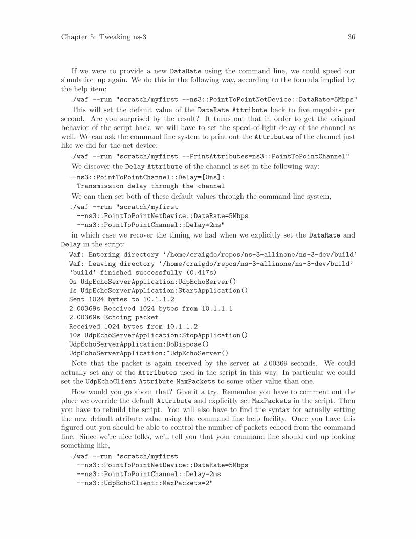
Chapter 5: Tweaking ns-3 36
If we were to provide a new DataRate using the command line, we could speed oursimulation up again. We do this in the following way, according to the formula implied bythe help item:./waf --run "scratch/myfirst --ns3::PointToPointNetDevice::DataRate=5Mbps"
This will set the default value of the DataRate Attribute back to five megabits persecond. Are you surprised by the result? It turns out that in order to get the originalbehavior of the script back, we will have to set the speed-of-light delay of the channel aswell. We can ask the command line system to print out the Attributes of the channel justlike we did for the net device:./waf --run "scratch/myfirst --PrintAttributes=ns3::PointToPointChannel"
We discover the Delay Attribute of the channel is set in the following way:--ns3::PointToPointChannel::Delay=[0ns]:
Transmission delay through the channel
We can then set both of these default values through the command line system,./waf --run "scratch/myfirst
--ns3::PointToPointNetDevice::DataRate=5Mbps--ns3::PointToPointChannel::Delay=2ms"
in which case we recover the timing we had when we explicitly set the DataRate andDelay in the script:Waf: Entering directory ‘/home/craigdo/repos/ns-3-allinone/ns-3-dev/build’Waf: Leaving directory ‘/home/craigdo/repos/ns-3-allinone/ns-3-dev/build’’build’ finished successfully (0.417s)0s UdpEchoServerApplication:UdpEchoServer()1s UdpEchoServerApplication:StartApplication()Sent 1024 bytes to 10.1.1.22.00369s Received 1024 bytes from 10.1.1.12.00369s Echoing packetReceived 1024 bytes from 10.1.1.210s UdpEchoServerApplication:StopApplication()UdpEchoServerApplication:DoDispose()UdpEchoServerApplication:~UdpEchoServer()
Note that the packet is again received by the server at 2.00369 seconds. We couldactually set any of the Attributes used in the script in this way. In particular we couldset the UdpEchoClient Attribute MaxPackets to some other value than one.
How would you go about that? Give it a try. Remember you have to comment out theplace we override the default Attribute and explicitly set MaxPackets in the script. Thenyou have to rebuild the script. You will also have to find the syntax for actually settingthe new default atribute value using the command line help facility. Once you have thisfigured out you should be able to control the number of packets echoed from the commandline. Since we’re nice folks, we’ll tell you that your command line should end up lookingsomething like,./waf --run "scratch/myfirst
--ns3::PointToPointNetDevice::DataRate=5Mbps--ns3::PointToPointChannel::Delay=2ms--ns3::UdpEchoClient::MaxPackets=2"
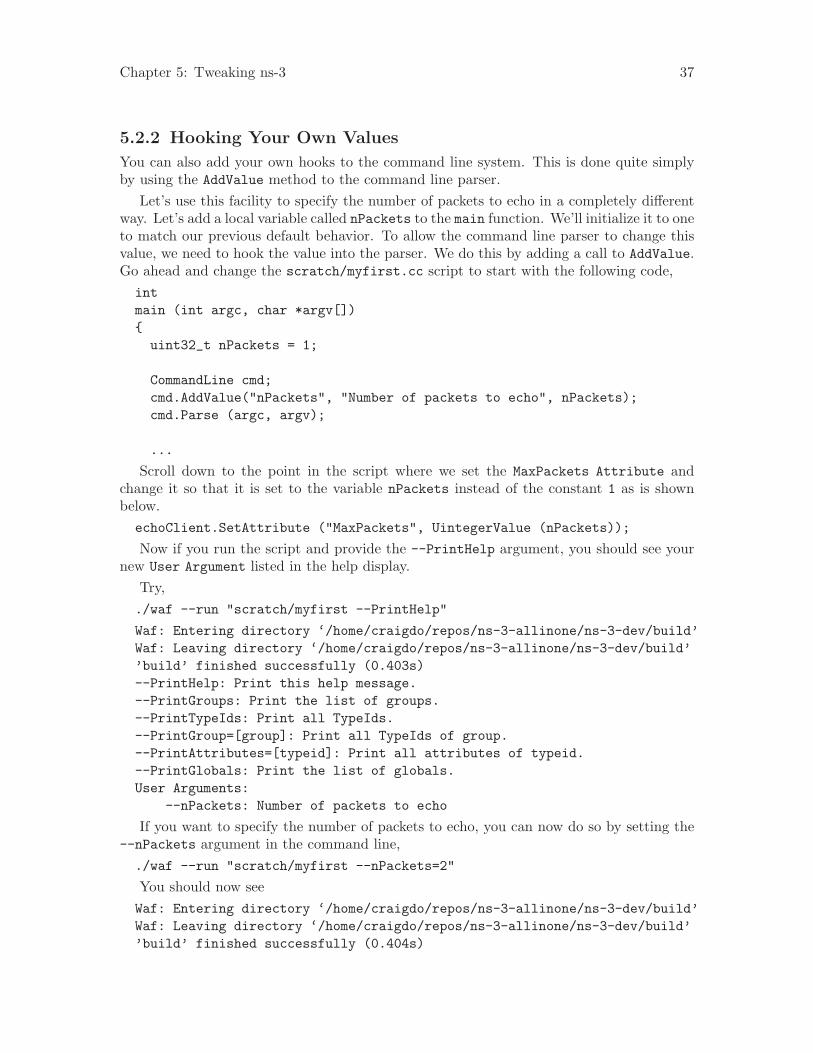
Chapter 5: Tweaking ns-3 37
5.2.2 Hooking Your Own Values
You can also add your own hooks to the command line system. This is done quite simplyby using the AddValue method to the command line parser.
Let’s use this facility to specify the number of packets to echo in a completely differentway. Let’s add a local variable called nPackets to the main function. We’ll initialize it to oneto match our previous default behavior. To allow the command line parser to change thisvalue, we need to hook the value into the parser. We do this by adding a call to AddValue.Go ahead and change the scratch/myfirst.cc script to start with the following code,intmain (int argc, char *argv[]){
uint32_t nPackets = 1;
CommandLine cmd;cmd.AddValue("nPackets", "Number of packets to echo", nPackets);cmd.Parse (argc, argv);
...
Scroll down to the point in the script where we set the MaxPackets Attribute andchange it so that it is set to the variable nPackets instead of the constant 1 as is shownbelow.echoClient.SetAttribute ("MaxPackets", UintegerValue (nPackets));
Now if you run the script and provide the --PrintHelp argument, you should see yournew User Argument listed in the help display.
Try,./waf --run "scratch/myfirst --PrintHelp"
Waf: Entering directory ‘/home/craigdo/repos/ns-3-allinone/ns-3-dev/build’Waf: Leaving directory ‘/home/craigdo/repos/ns-3-allinone/ns-3-dev/build’’build’ finished successfully (0.403s)--PrintHelp: Print this help message.--PrintGroups: Print the list of groups.--PrintTypeIds: Print all TypeIds.--PrintGroup=[group]: Print all TypeIds of group.--PrintAttributes=[typeid]: Print all attributes of typeid.--PrintGlobals: Print the list of globals.User Arguments:
--nPackets: Number of packets to echo
If you want to specify the number of packets to echo, you can now do so by setting the--nPackets argument in the command line,./waf --run "scratch/myfirst --nPackets=2"
You should now seeWaf: Entering directory ‘/home/craigdo/repos/ns-3-allinone/ns-3-dev/build’Waf: Leaving directory ‘/home/craigdo/repos/ns-3-allinone/ns-3-dev/build’’build’ finished successfully (0.404s)
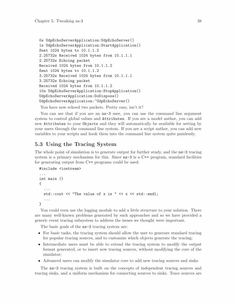
Chapter 5: Tweaking ns-3 38
0s UdpEchoServerApplication:UdpEchoServer()1s UdpEchoServerApplication:StartApplication()Sent 1024 bytes to 10.1.1.22.25732s Received 1024 bytes from 10.1.1.12.25732s Echoing packetReceived 1024 bytes from 10.1.1.2Sent 1024 bytes to 10.1.1.23.25732s Received 1024 bytes from 10.1.1.13.25732s Echoing packetReceived 1024 bytes from 10.1.1.210s UdpEchoServerApplication:StopApplication()UdpEchoServerApplication:DoDispose()UdpEchoServerApplication:~UdpEchoServer()
You have now echoed two packets. Pretty easy, isn’t it?You can see that if you are an ns-3 user, you can use the command line argument
system to control global values and Attributes. If you are a model author, you can addnew Attributes to your Objects and they will automatically be available for setting byyour users through the command line system. If you are a script author, you can add newvariables to your scripts and hook them into the command line system quite painlessly.
5.3 Using the Tracing System
The whole point of simulation is to generate output for further study, and the ns-3 tracingsystem is a primary mechanism for this. Since ns-3 is a C++ program, standard facilitiesfor generating output from C++ programs could be used:#include <iostream>...int main (){
...std::cout << "The value of x is " << x << std::endl;...
}
You could even use the logging module to add a little structure to your solution. Thereare many well-known problems generated by such approaches and so we have provided ageneric event tracing subsystem to address the issues we thought were important.
The basic goals of the ns-3 tracing system are:• For basic tasks, the tracing system should allow the user to generate standard tracing
for popular tracing sources, and to customize which objects generate the tracing;• Intermediate users must be able to extend the tracing system to modify the output
format generated, or to insert new tracing sources, without modifying the core of thesimulator;
• Advanced users can modify the simulator core to add new tracing sources and sinks.
The ns-3 tracing system is built on the concepts of independent tracing sources andtracing sinks, and a uniform mechanism for connecting sources to sinks. Trace sources are
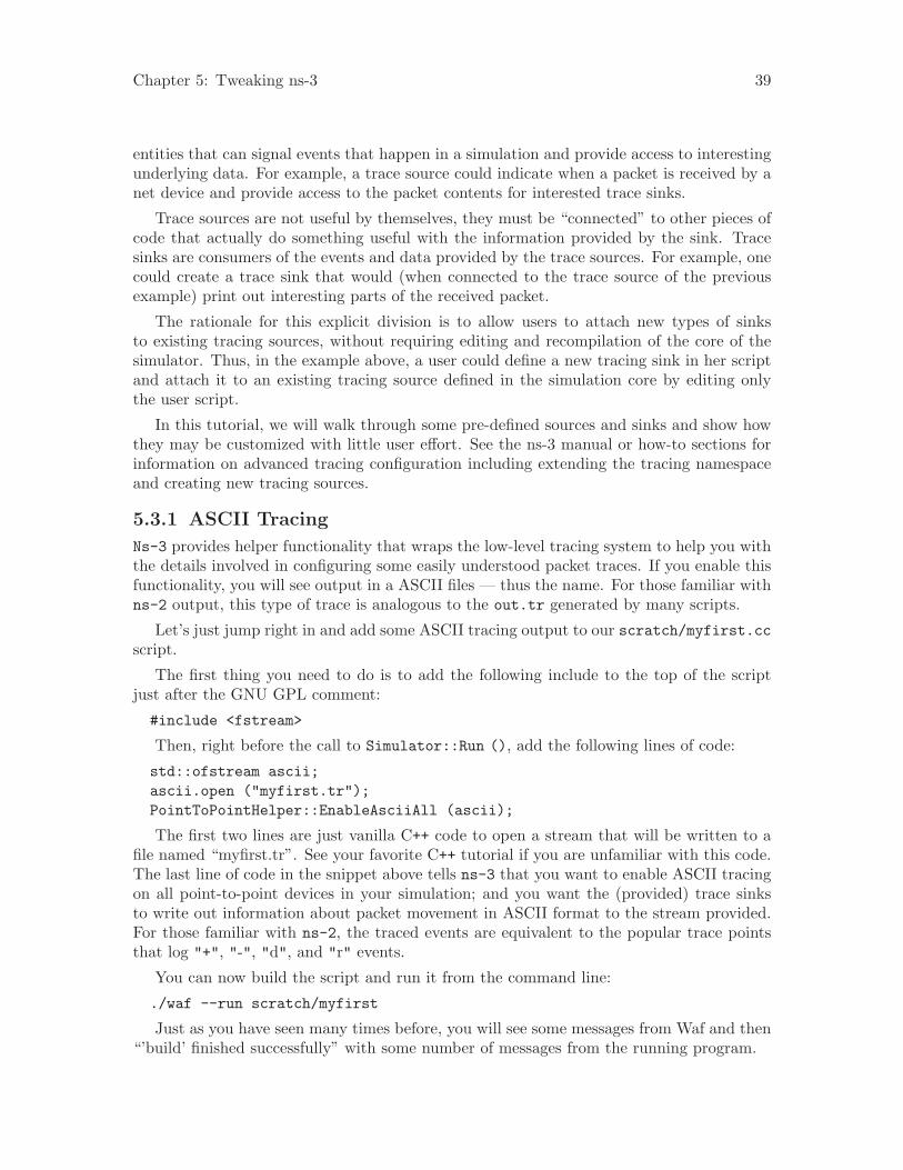
Chapter 5: Tweaking ns-3 39
entities that can signal events that happen in a simulation and provide access to interestingunderlying data. For example, a trace source could indicate when a packet is received by anet device and provide access to the packet contents for interested trace sinks.
Trace sources are not useful by themselves, they must be “connected” to other pieces ofcode that actually do something useful with the information provided by the sink. Tracesinks are consumers of the events and data provided by the trace sources. For example, onecould create a trace sink that would (when connected to the trace source of the previousexample) print out interesting parts of the received packet.
The rationale for this explicit division is to allow users to attach new types of sinksto existing tracing sources, without requiring editing and recompilation of the core of thesimulator. Thus, in the example above, a user could define a new tracing sink in her scriptand attach it to an existing tracing source defined in the simulation core by editing onlythe user script.
In this tutorial, we will walk through some pre-defined sources and sinks and show howthey may be customized with little user effort. See the ns-3 manual or how-to sections forinformation on advanced tracing configuration including extending the tracing namespaceand creating new tracing sources.
5.3.1 ASCII Tracing
Ns-3 provides helper functionality that wraps the low-level tracing system to help you withthe details involved in configuring some easily understood packet traces. If you enable thisfunctionality, you will see output in a ASCII files — thus the name. For those familiar withns-2 output, this type of trace is analogous to the out.tr generated by many scripts.
Let’s just jump right in and add some ASCII tracing output to our scratch/myfirst.ccscript.
The first thing you need to do is to add the following include to the top of the scriptjust after the GNU GPL comment:
#include <fstream>
Then, right before the call to Simulator::Run (), add the following lines of code:
std::ofstream ascii;ascii.open ("myfirst.tr");PointToPointHelper::EnableAsciiAll (ascii);
The first two lines are just vanilla C++ code to open a stream that will be written to afile named “myfirst.tr”. See your favorite C++ tutorial if you are unfamiliar with this code.The last line of code in the snippet above tells ns-3 that you want to enable ASCII tracingon all point-to-point devices in your simulation; and you want the (provided) trace sinksto write out information about packet movement in ASCII format to the stream provided.For those familiar with ns-2, the traced events are equivalent to the popular trace pointsthat log "+", "-", "d", and "r" events.
You can now build the script and run it from the command line:
./waf --run scratch/myfirst
Just as you have seen many times before, you will see some messages from Waf and then“’build’ finished successfully” with some number of messages from the running program.

Chapter 5: Tweaking ns-3 40
When it ran, the program will have created a file named myfirst.tr. Because of theway that Waf works, the file is not created in the local directory, it is created at the top-leveldirectory of the repository by default. If you want to control where the traces are savedyou can use the --cwd option of Waf to specify this. We have not done so, thus we needto change into the top level directory of our repo and take a look at the ASCII trace filemyfirst.tr in your favorite editor.
5.3.1.1 Parsing Ascii Traces
There’s a lot of information there in a pretty dense form, but the first thing to notice isthat there are a number of distinct lines in this file. It may be difficult to see this clearlyunless you widen your window considerably.
Each line in the file corresponds to a trace event. In this case we are tracing eventson the transmit queue present in every point-to-point net device in the simulation. Thetransmit queue is a queue through which every packet destined for a point-to-point channelmust pass. Note that each line in the trace file begins with a lone character (has a spaceafter it). This character will have the following meaning:
• +: An enqueue operation occurred on the device queue;• -: A dequeue operation occurred on the device queue;• d: A packet was dropped, typically because the queue was full;• r: A packet was received by the net device.
Let’s take a more detailed view of the first line in the trace file. I’ll break it down intosections (indented for clarity) with a two digit reference number on the left side:
00 +01 202 /NodeList/0/DeviceList/0/$ns3::PointToPointNetDevice/TxQueue/Enqueue03 ns3::PppHeader (04 Point-to-Point Protocol: IP (0x0021))05 ns3::Ipv4Header (06 tos 0x0 ttl 64 id 0 protocol 17 offset 0 flags [none]07 length: 1052 10.1.1.1 > 10.1.1.2)08 ns3::UdpHeader (09 length: 1032 49153 > 9)10 Payload (size=1024)
The first line of this expanded trace event (reference number 00) is the operation. Wehave a + character, so this corresponds to an enqueue operation on the transmit queue. Thesecond line (reference 01) is the simulation time expressed in seconds. You may recall thatwe asked the UdpEchoClientApplication to start sending packets at two seconds. Herewe see confirmation that this is, indeed, happening.
The next line of the example trace (reference 02) tell us which trace source originated thisevent (expressed in the tracing namespace). You can think of the tracing namespace some-what like you would a filesystem namespace. The root of the namespace is the NodeList.This corresponds to a container managed in the ns-3 core code that contains all of thenodes that are created in a script. Just as a filesystem may have directories under the root,we may have node numbers in the NodeList. The string /NodeList/0 therefore refers to
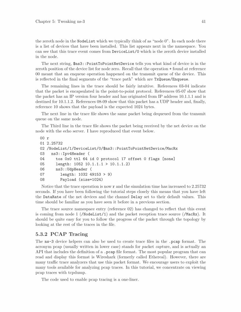
Chapter 5: Tweaking ns-3 41
the zeroth node in the NodeList which we typically think of as “node 0”. In each node thereis a list of devices that have been installed. This list appears next in the namespace. Youcan see that this trace event comes from DeviceList/0 which is the zeroth device installedin the node.
The next string, $ns3::PointToPointNetDevice tells you what kind of device is in thezeroth position of the device list for node zero. Recall that the operation + found at reference00 meant that an enqueue operation happened on the transmit queue of the device. Thisis reflected in the final segments of the “trace path” which are TxQueue/Enqueue.
The remaining lines in the trace should be fairly intuitive. References 03-04 indicatethat the packet is encapsulated in the point-to-point protocol. References 05-07 show thatthe packet has an IP version four header and has originated from IP address 10.1.1.1 and isdestined for 10.1.1.2. References 08-09 show that this packet has a UDP header and, finally,reference 10 shows that the payload is the expected 1024 bytes.
The next line in the trace file shows the same packet being dequeued from the transmitqueue on the same node.
The Third line in the trace file shows the packet being received by the net device on thenode with the echo server. I have reproduced that event below.
00 r01 2.2573202 /NodeList/1/DeviceList/0/$ns3::PointToPointNetDevice/MacRx03 ns3::Ipv4Header (04 tos 0x0 ttl 64 id 0 protocol 17 offset 0 flags [none]05 length: 1052 10.1.1.1 > 10.1.1.2)06 ns3::UdpHeader (07 length: 1032 49153 > 9)08 Payload (size=1024)
Notice that the trace operation is now r and the simulation time has increased to 2.25732seconds. If you have been following the tutorial steps closely this means that you have leftthe DataRate of the net devices and the channel Delay set to their default values. Thistime should be familiar as you have seen it before in a previous section.
The trace source namespace entry (reference 02) has changed to reflect that this eventis coming from node 1 (/NodeList/1) and the packet reception trace source (/MacRx). Itshould be quite easy for you to follow the progress of the packet through the topology bylooking at the rest of the traces in the file.
5.3.2 PCAP Tracing
The ns-3 device helpers can also be used to create trace files in the .pcap format. Theacronym pcap (usually written in lower case) stands for packet capture, and is actually anAPI that includes the definition of a .pcap file format. The most popular program that canread and display this format is Wireshark (formerly called Ethereal). However, there aremany traffic trace analyzers that use this packet format. We encourage users to exploit themany tools available for analyzing pcap traces. In this tutorial, we concentrate on viewingpcap traces with tcpdump.
The code used to enable pcap tracing is a one-liner.
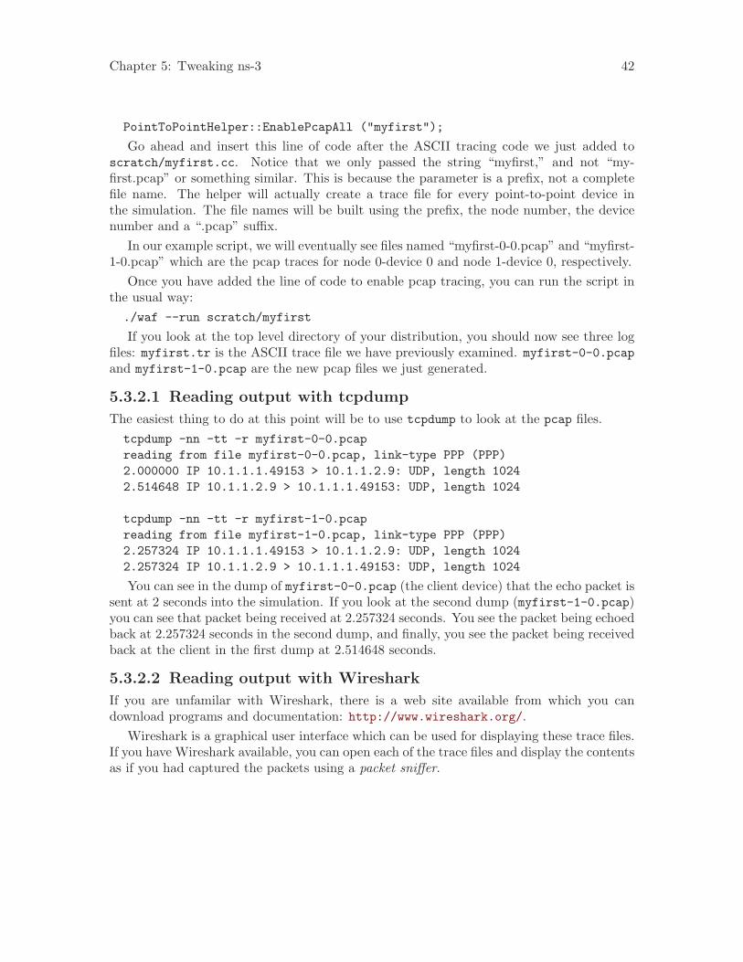
Chapter 5: Tweaking ns-3 42
PointToPointHelper::EnablePcapAll ("myfirst");
Go ahead and insert this line of code after the ASCII tracing code we just added toscratch/myfirst.cc. Notice that we only passed the string “myfirst,” and not “my-first.pcap” or something similar. This is because the parameter is a prefix, not a completefile name. The helper will actually create a trace file for every point-to-point device inthe simulation. The file names will be built using the prefix, the node number, the devicenumber and a “.pcap” suffix.
In our example script, we will eventually see files named “myfirst-0-0.pcap” and “myfirst-1-0.pcap” which are the pcap traces for node 0-device 0 and node 1-device 0, respectively.
Once you have added the line of code to enable pcap tracing, you can run the script inthe usual way:./waf --run scratch/myfirst
If you look at the top level directory of your distribution, you should now see three logfiles: myfirst.tr is the ASCII trace file we have previously examined. myfirst-0-0.pcapand myfirst-1-0.pcap are the new pcap files we just generated.
5.3.2.1 Reading output with tcpdump
The easiest thing to do at this point will be to use tcpdump to look at the pcap files.tcpdump -nn -tt -r myfirst-0-0.pcapreading from file myfirst-0-0.pcap, link-type PPP (PPP)2.000000 IP 10.1.1.1.49153 > 10.1.1.2.9: UDP, length 10242.514648 IP 10.1.1.2.9 > 10.1.1.1.49153: UDP, length 1024
tcpdump -nn -tt -r myfirst-1-0.pcapreading from file myfirst-1-0.pcap, link-type PPP (PPP)2.257324 IP 10.1.1.1.49153 > 10.1.1.2.9: UDP, length 10242.257324 IP 10.1.1.2.9 > 10.1.1.1.49153: UDP, length 1024
You can see in the dump of myfirst-0-0.pcap (the client device) that the echo packet issent at 2 seconds into the simulation. If you look at the second dump (myfirst-1-0.pcap)you can see that packet being received at 2.257324 seconds. You see the packet being echoedback at 2.257324 seconds in the second dump, and finally, you see the packet being receivedback at the client in the first dump at 2.514648 seconds.
5.3.2.2 Reading output with Wireshark
If you are unfamilar with Wireshark, there is a web site available from which you candownload programs and documentation: http://www.wireshark.org/.
Wireshark is a graphical user interface which can be used for displaying these trace files.If you have Wireshark available, you can open each of the trace files and display the contentsas if you had captured the packets using a packet sniffer.
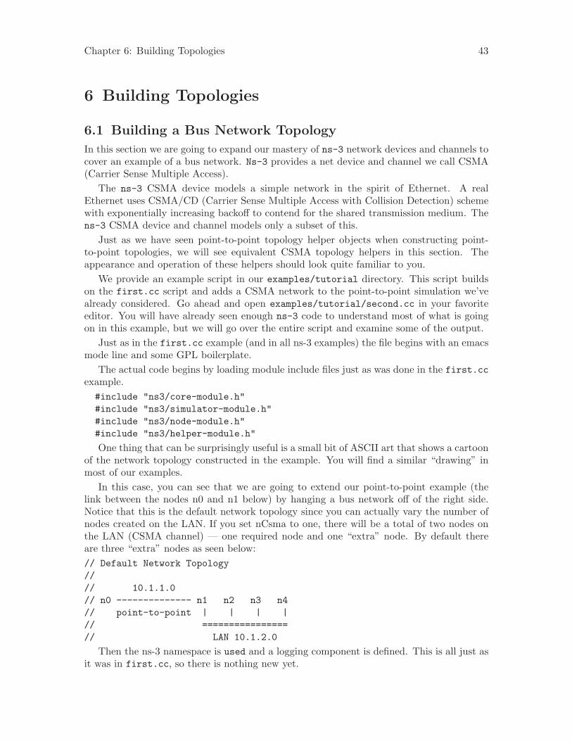
Chapter 6: Building Topologies 43
6 Building Topologies
6.1 Building a Bus Network Topology
In this section we are going to expand our mastery of ns-3 network devices and channels tocover an example of a bus network. Ns-3 provides a net device and channel we call CSMA(Carrier Sense Multiple Access).
The ns-3 CSMA device models a simple network in the spirit of Ethernet. A realEthernet uses CSMA/CD (Carrier Sense Multiple Access with Collision Detection) schemewith exponentially increasing backoff to contend for the shared transmission medium. Thens-3 CSMA device and channel models only a subset of this.
Just as we have seen point-to-point topology helper objects when constructing point-to-point topologies, we will see equivalent CSMA topology helpers in this section. Theappearance and operation of these helpers should look quite familiar to you.
We provide an example script in our examples/tutorial directory. This script buildson the first.cc script and adds a CSMA network to the point-to-point simulation we’vealready considered. Go ahead and open examples/tutorial/second.cc in your favoriteeditor. You will have already seen enough ns-3 code to understand most of what is goingon in this example, but we will go over the entire script and examine some of the output.
Just as in the first.cc example (and in all ns-3 examples) the file begins with an emacsmode line and some GPL boilerplate.
The actual code begins by loading module include files just as was done in the first.ccexample.#include "ns3/core-module.h"#include "ns3/simulator-module.h"#include "ns3/node-module.h"#include "ns3/helper-module.h"
One thing that can be surprisingly useful is a small bit of ASCII art that shows a cartoonof the network topology constructed in the example. You will find a similar “drawing” inmost of our examples.
In this case, you can see that we are going to extend our point-to-point example (thelink between the nodes n0 and n1 below) by hanging a bus network off of the right side.Notice that this is the default network topology since you can actually vary the number ofnodes created on the LAN. If you set nCsma to one, there will be a total of two nodes onthe LAN (CSMA channel) — one required node and one “extra” node. By default thereare three “extra” nodes as seen below:// Default Network Topology//// 10.1.1.0// n0 -------------- n1 n2 n3 n4// point-to-point | | | |// ================// LAN 10.1.2.0
Then the ns-3 namespace is used and a logging component is defined. This is all just asit was in first.cc, so there is nothing new yet.

Chapter 6: Building Topologies 44
using namespace ns3;
NS_LOG_COMPONENT_DEFINE ("SecondScriptExample");
The main program begins with a slightly different twist. We use a verbose flag to de-termine whether or not the UdpEchoClientApplication and UdpEchoServerApplicationlogging components are enabled. This flag defaults to true (the logging components areenabled) but allows us to turn off logging during regression testing of this example.
You will see some familiar code that will allow you to change the number of devices onthe CSMA network via command line argument. We did something similar when we allowedthe number of packets sent to be changed in the section on command line arguments. Thelast line makes sure you have at least one “extra” node.
The code consists of variations of previously covered API so you should be entirelycomfortable with the following code at this point in the tutorial.bool verbose = true;uint32_t nCsma = 3;
CommandLine cmd;cmd.AddValue (‘‘nCsma’’, ‘‘Number of \"extra\" CSMA nodes/devices’’, nCsma);cmd.AddValue (‘‘verbose’’, ‘‘Tell echo applications to log if true’’, verbose);
cmd.Parse (argc,argv);
if (verbose){LogComponentEnable(‘‘UdpEchoClientApplication’’, LOG_LEVEL_INFO);LogComponentEnable(‘‘UdpEchoServerApplication’’, LOG_LEVEL_INFO);
}
nCsma = nCsma == 0 ? 1 : nCsma;
The next step is to create two nodes that we will connect via the point-to-point link.The NodeContainer is used to do this just as was done in first.cc.NodeContainer p2pNodes;p2pNodes.Create (2);
Next, we declare another NodeContainer to hold the nodes that will be part of the bus(CSMA) network. First, we just instantiate the container object itself.NodeContainer csmaNodes;csmaNodes.Add (p2pNodes.Get (1));csmaNodes.Create (nCsma);
The next line of code Gets the first node (as in having an index of one) from the point-to-point node container and adds it to the container of nodes that will get CSMA devices. Thenode in question is going to end up with a point-to-point device and a CSMA device. Wethen create a number of “extra” nodes that compose the remainder of the CSMA network.Since we already have one node in the CSMA network – the one that will have both a point-to-point and CSMA net device, the number of “extra” nodes means the number nodes youdesire in the CSMA section minus one.
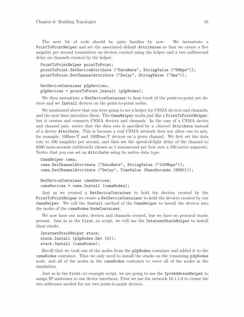
Chapter 6: Building Topologies 45
The next bit of code should be quite familiar by now. We instantiate aPointToPointHelper and set the associated default Attributes so that we create a fivemegabit per second transmitter on devices created using the helper and a two milliseconddelay on channels created by the helper.
PointToPointHelper pointToPoint;pointToPoint.SetDeviceAttribute ("DataRate", StringValue ("5Mbps"));pointToPoint.SetChannelAttribute ("Delay", StringValue ("2ms"));
NetDeviceContainer p2pDevices;p2pDevices = pointToPoint.Install (p2pNodes);
We then instantiate a NetDeviceContainer to keep track of the point-to-point net de-vices and we Install devices on the point-to-point nodes.
We mentioned above that you were going to see a helper for CSMA devices and channels,and the next lines introduce them. The CsmaHelper works just like a PointToPointHelper,but it creates and connects CSMA devices and channels. In the case of a CSMA deviceand channel pair, notice that the data rate is specified by a channel Attribute insteadof a device Attribute. This is because a real CSMA network does not allow one to mix,for example, 10Base-T and 100Base-T devices on a given channel. We first set the datarate to 100 megabits per second, and then set the speed-of-light delay of the channel to6560 nano-seconds (arbitrarily chosen as 1 nanosecond per foot over a 100 meter segment).Notice that you can set an Attribute using its native data type.
CsmaHelper csma;csma.SetChannelAttribute ("DataRate", StringValue ("100Mbps"));csma.SetChannelAttribute ("Delay", TimeValue (NanoSeconds (6560)));
NetDeviceContainer csmaDevices;csmaDevices = csma.Install (csmaNodes);
Just as we created a NetDeviceContainer to hold the devices created by thePointToPointHelper we create a NetDeviceContainer to hold the devices created by ourCsmaHelper. We call the Install method of the CsmaHelper to install the devices intothe nodes of the csmaNodes NodeContainer.
We now have our nodes, devices and channels created, but we have no protocol stackspresent. Just as in the first.cc script, we will use the InternetStackHelper to installthese stacks.
InternetStackHelper stack;stack.Install (p2pNodes.Get (0));stack.Install (csmaNodes);
Recall that we took one of the nodes from the p2pNodes container and added it to thecsmaNodes container. Thus we only need to install the stacks on the remaining p2pNodesnode, and all of the nodes in the csmaNodes container to cover all of the nodes in thesimulation.
Just as in the first.cc example script, we are going to use the Ipv4AddressHelper toassign IP addresses to our device interfaces. First we use the network 10.1.1.0 to create thetwo addresses needed for our two point-to-point devices.
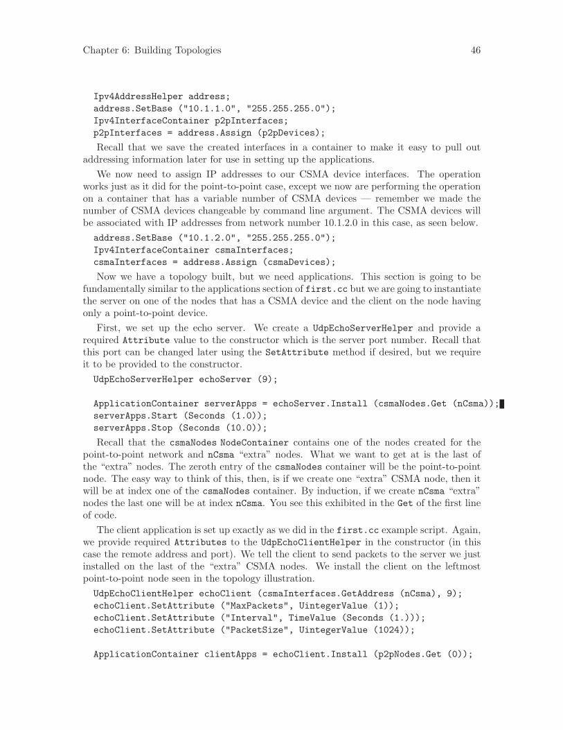
Chapter 6: Building Topologies 46
Ipv4AddressHelper address;address.SetBase ("10.1.1.0", "255.255.255.0");Ipv4InterfaceContainer p2pInterfaces;p2pInterfaces = address.Assign (p2pDevices);
Recall that we save the created interfaces in a container to make it easy to pull outaddressing information later for use in setting up the applications.
We now need to assign IP addresses to our CSMA device interfaces. The operationworks just as it did for the point-to-point case, except we now are performing the operationon a container that has a variable number of CSMA devices — remember we made thenumber of CSMA devices changeable by command line argument. The CSMA devices willbe associated with IP addresses from network number 10.1.2.0 in this case, as seen below.address.SetBase ("10.1.2.0", "255.255.255.0");Ipv4InterfaceContainer csmaInterfaces;csmaInterfaces = address.Assign (csmaDevices);
Now we have a topology built, but we need applications. This section is going to befundamentally similar to the applications section of first.cc but we are going to instantiatethe server on one of the nodes that has a CSMA device and the client on the node havingonly a point-to-point device.
First, we set up the echo server. We create a UdpEchoServerHelper and provide arequired Attribute value to the constructor which is the server port number. Recall thatthis port can be changed later using the SetAttribute method if desired, but we requireit to be provided to the constructor.UdpEchoServerHelper echoServer (9);
ApplicationContainer serverApps = echoServer.Install (csmaNodes.Get (nCsma));serverApps.Start (Seconds (1.0));serverApps.Stop (Seconds (10.0));
Recall that the csmaNodes NodeContainer contains one of the nodes created for thepoint-to-point network and nCsma “extra” nodes. What we want to get at is the last ofthe “extra” nodes. The zeroth entry of the csmaNodes container will be the point-to-pointnode. The easy way to think of this, then, is if we create one “extra” CSMA node, then itwill be at index one of the csmaNodes container. By induction, if we create nCsma “extra”nodes the last one will be at index nCsma. You see this exhibited in the Get of the first lineof code.
The client application is set up exactly as we did in the first.cc example script. Again,we provide required Attributes to the UdpEchoClientHelper in the constructor (in thiscase the remote address and port). We tell the client to send packets to the server we justinstalled on the last of the “extra” CSMA nodes. We install the client on the leftmostpoint-to-point node seen in the topology illustration.UdpEchoClientHelper echoClient (csmaInterfaces.GetAddress (nCsma), 9);echoClient.SetAttribute ("MaxPackets", UintegerValue (1));echoClient.SetAttribute ("Interval", TimeValue (Seconds (1.)));echoClient.SetAttribute ("PacketSize", UintegerValue (1024));
ApplicationContainer clientApps = echoClient.Install (p2pNodes.Get (0));
Chapter 6: Building Topologies 47
clientApps.Start (Seconds (2.0));clientApps.Stop (Seconds (10.0));
Since we have actually built an internetwork here, we need some form of internetworkrouting. ns-3 provides what we call global routing to help you out. Global routing takesadvantage of the fact that the entire internetwork is accessible in the simulation and runsthrough the all of the nodes created for the simulation — it does the hard work of settingup routing for you without having to configure routers.
Basically, what happens is that each node behaves as if it were an OSPF router thatcommunicates instantly and magically with all other routers behind the scenes. Each nodegenerates link advertisements and communicates them directly to a global route managerwhich uses this global information to construct the routing tables for each node. Settingup this form of routing is a one-liner:
Ipv4GlobalRoutingHelper::PopulateRoutingTables ();
Next we enable pcap tracing. The first line of code to enable pcap tracing in the point-to-point helper should be familiar to you by now. The second line enables pcap tracing inthe CSMA helper and there is an extra parameter you haven’t encountered yet.
PointToPointHelper::EnablePcapAll ("second");CsmaHelper::EnablePcap ("second", csmaDevices.Get (1), true);
The CSMA network is a multi-point-to-point network. This means that there can (andare in this case) multiple endpoints on a shared medium. Each of these endpoints has a netdevice associated with it. There are two basic alternatives to gathering trace informationfrom such a network. One way is to create a trace file for each net device and store only thepackets that are emitted or consumed by that net device. Another way is to pick one of thedevices and place it in promiscuous mode. That single device then “sniffs” the network forall packets and stores them in a single pcap file. This is how tcpdump, for example, works.That final parameter tells the CSMA helper whether or not to arrange to capture packetsin promiscuous mode.
In this example, we are going to select one of the devices on the CSMA network and askit to perform a promiscuous sniff of the network, thereby emulating what tcpdump woulddo. If you were on a Linux machine you might do something like tcpdump -i eth0 to getthe trace. In this case, we specify the device using csmaDevices.Get(1), which selectsthe first device in the container. Setting the final parameter to true enables promiscuouscaptures.
The last section of code just runs and cleans up the simulation just like the first.ccexample.
Simulator::Run ();Simulator::Destroy ();return 0;
}
In order to run this example, copy the second.cc example script into the scratch di-rectory and use waf to build just as you did with the first.cc example. If you are in thetop-level directory of the repository you just type,
cp examples/tutorial/second.cc scratch/mysecond.cc./waf
Chapter 6: Building Topologies 48
Warning: We use the file second.cc as one of our regression tests to verify that it worksexactly as we think it should in order to make your tutorial experience a positive one.This means that an executable named second already exists in the project. To avoid anyconfusion about what you are executing, please do the renaming to mysecond.cc suggestedabove.
If you are following the tutorial religiously (you are, aren’t you) you will still have theNS LOG variable set, so go ahead and clear that variable and run the program.
export NS_LOG=./waf --run scratch/mysecond
Since we have set up the UDP echo applications to log just as we did in first.cc, youwill see similar output when you run the script.
Waf: Entering directory ‘/home/craigdo/repos/ns-3-allinone/ns-3-dev/build’Waf: Leaving directory ‘/home/craigdo/repos/ns-3-allinone/ns-3-dev/build’’build’ finished successfully (0.415s)Sent 1024 bytes to 10.1.2.4Received 1024 bytes from 10.1.1.1Received 1024 bytes from 10.1.2.4
Recall that the first message, “Sent 1024 bytes to 10.1.2.4,” is the UDP echo clientsending a packet to the server. In this case, the server is on a different network (10.1.2.0).The second message, “Received 1024 bytes from 10.1.1.1,” is from the UDP echo server,generated when it receives the echo packet. The final message, “Received 1024 bytes from10.1.2.4,” is from the echo client, indicating that it has received its echo back from theserver.
If you now go and look in the top level directory, you will find three trace files:
second-0-0.pcap second-1-0.pcap second-2-0.pcap
Let’s take a moment to look at the naming of these files. They all have the same form,<name>-<node>-<device>.pcap. For example, the first file in the listing is second-0-0.pcap which is the pcap trace from node zero, device zero. This is the point-to-point netdevice on node zero. The file second-1-0.pcap is the pcap trace for device zero on nodeone, also a point-to-point net device; and the file second-2-0.pcap is the pcap trace fordevice zero on node two.
If you refer back to the topology illustration at the start of the section, you will see thatnode zero is the leftmost node of the point-to-point link and node one is the node thathas both a point-to-point device and a CSMA device. You will see that node two is thefirst “extra” node on the CSMA network and its device zero was selected as the device tocapture the promiscuous-mode trace.
Now, let’s follow the echo packet through the internetwork. First, do a tcpdump of thetrace file for the leftmost point-to-point node — node zero.
tcpdump -nn -tt -r second-0-0.pcap
You should see the contents of the pcap file displayed:
reading from file second-0-0.pcap, link-type PPP (PPP)2.000000 IP 10.1.1.1.49153 > 10.1.2.4.9: UDP, length 10242.007602 IP 10.1.2.4.9 > 10.1.1.1.49153: UDP, length 1024
Chapter 6: Building Topologies 49
The first line of the dump indicates that the link type is PPP (point-to-point) which weexpect. You then see the echo packet leaving node zero via the device associated with IPaddress 10.1.1.1 headed for IP address 10.1.2.4 (the rightmost CSMA node). This packetwill move over the point-to-point link and be received by the point-to-point net device onnode one. Let’s take a look:tcpdump -nn -tt -r second-1-0.pcap
You should now see the pcap trace output of the other side of the point-to-point link:reading from file second-1-0.pcap, link-type PPP (PPP)2.003686 IP 10.1.1.1.49153 > 10.1.2.4.9: UDP, length 10242.003915 IP 10.1.2.4.9 > 10.1.1.1.49153: UDP, length 1024
Here we see that the link type is also PPP as we would expect. You see the packet fromIP address 10.1.1.1 (that was sent at 2.000000 seconds) headed toward IP address 10.1.2.4appear on this interface. Now, internally to this node, the packet will be forwarded tothe CSMA interface and we should see it pop out on that device headed for its ultimatedestination.
Remember that we selected node 2 as the promiscuous sniffer node for the CSMA networkso let’s then look at second-2-0.pcap and see if its there.tcpdump -nn -tt -r second-2-0.pcap
You should now see the promiscuous dump of node two, device zero:reading from file second-2-0.pcap, link-type EN10MB (Ethernet)2.003696 arp who-has 10.1.2.4 (ff:ff:ff:ff:ff:ff) tell 10.1.2.12.003707 arp reply 10.1.2.4 is-at 00:00:00:00:00:062.003801 IP 10.1.1.1.49153 > 10.1.2.4.9: UDP, length 10242.003811 arp who-has 10.1.2.1 (ff:ff:ff:ff:ff:ff) tell 10.1.2.42.003822 arp reply 10.1.2.1 is-at 00:00:00:00:00:032.003915 IP 10.1.2.4.9 > 10.1.1.1.49153: UDP, length 1024
As you can see, the link type is now “Ethernet”. Something new has appeared, though.The bus network needs ARP, the Address Resolution Protocol. Node one knows it needsto send the packet to IP address 10.1.2.4, but it doesn’t know the MAC address of thecorresponding node. It broadcasts on the CSMA network (ff:ff:ff:ff:ff:ff) asking for thedevice that has IP address 10.1.2.4. In this case, the rightmost node replies saying it isat MAC address 00:00:00:00:00:06. Note that node two is not directly involved in thisexchange, but is sniffing the network and reporting all of the traffic it sees.
This exchange is seen in the following lines,2.003696 arp who-has 10.1.2.4 (ff:ff:ff:ff:ff:ff) tell 10.1.2.12.003707 arp reply 10.1.2.4 is-at 00:00:00:00:00:06
Then node one, device one goes ahead and sends the echo packet to the UDP echo serverat IP address 10.1.2.4.2.003801 IP 10.1.1.1.49153 > 10.1.2.4.9: UDP, length 1024
The server receives the echo request and turns the packet around trying to send it backto the source. The server knows that this address is on another network that it reaches viaIP address 10.1.2.1. This is because we initialized global routing and it has figured all ofthis out for us. But, the echo server node doesn’t know the MAC address of the first CSMAnode, so it has to ARP for it just like the first CSMA node had to do.
Chapter 6: Building Topologies 50
2.003811 arp who-has 10.1.2.1 (ff:ff:ff:ff:ff:ff) tell 10.1.2.42.003822 arp reply 10.1.2.1 is-at 00:00:00:00:00:03
The server then sends the echo back to the forwarding node.2.003915 IP 10.1.2.4.9 > 10.1.1.1.49153: UDP, length 1024
Looking back at the rightmost node of the point-to-point link,tcpdump -nn -tt -r second-1-0.pcap
You can now see the echoed packet coming back onto the point-to-point link as the lastline of the trace dump.reading from file second-1-0.pcap, link-type PPP (PPP)2.003686 IP 10.1.1.1.49153 > 10.1.2.4.9: UDP, length 10242.003915 IP 10.1.2.4.9 > 10.1.1.1.49153: UDP, length 1024
Lastly, you can look back at the node that originated the echotcpdump -nn -tt -r second-0-0.pcap
and see that the echoed packet arrives back at the source at 2.007602 seconds,reading from file second-0-0.pcap, link-type PPP (PPP)2.000000 IP 10.1.1.1.49153 > 10.1.2.4.9: UDP, length 10242.007602 IP 10.1.2.4.9 > 10.1.1.1.49153: UDP, length 1024
Finally, recall that we added the ability to control the number of CSMA devices in thesimulation by command line argument. You can change this argument in the same way aswhen we looked at changing the number of packets echoed in the first.cc example. Tryrunning the program with the number of “extra” devices set to four:./waf --run "scratch/mysecond --nCsma=4"
You should now see,Waf: Entering directory ‘/home/craigdo/repos/ns-3-allinone/ns-3-dev/build’Waf: Leaving directory ‘/home/craigdo/repos/ns-3-allinone/ns-3-dev/build’’build’ finished successfully (0.405s)Sent 1024 bytes to 10.1.2.5Received 1024 bytes from 10.1.1.1Received 1024 bytes from 10.1.2.5
Notice that the echo server has now been relocated to the last of the CSMA nodes, whichis 10.1.2.5 instead of the default case, 10.1.2.4.
It is possible that you may not be satisfied with a trace file generated by a bystander inthe CSMA network. You may really want to get a trace from a single device and you maynot be interested in any other traffic on the network. You can do this fairly easily/
Let’s take a look at scratch/mysecond.cc and add that code enabling us to be morespecific. ns-3 helpers provide methods that take a node number and device number asparameters. Go ahead and replace the EnablePcap calls with the calls below.PointToPointHelper::EnablePcap ("second", p2pNodes.Get (0)->GetId (), 0);CsmaHelper::EnablePcap ("second", csmaNodes.Get (nCsma)->GetId (), 0, false);CsmaHelper::EnablePcap ("second", csmaNodes.Get (nCsma-1)->GetId (), 0, false);
We know that we want to create a pcap file with the base name "second" and we alsoknow that the device of interest in both cases is going to be zero, so those parameters arenot really interesting.
Chapter 6: Building Topologies 51
In order to get the node number, you have two choices: first, nodes are numbered in amonotonically increasing fashion starting from zero in the order in which you created them.One way to get a node number is to figure this number out “manually” by contemplatingthe order of node creation. If you take a look at the network topology illustration at thebeginning of the file, we did this for you and you can see that the last CSMA node is goingto be node number nCsma + 1. This approach can become annoyingly difficult in largersimulations.
An alternate way, which we use here, is to realize that the NodeContainers containpointers to ns-3 Node Objects. The Node Object has a method called GetId which willreturn that node’s ID, which is the node number we seek. Let’s go take a look at theDoxygen for the Node and locate that method, which is further down in the ns-3 core codethan we’ve seen so far; but sometimes you have to search diligently for useful things.
Go to the Doxygen documentation for your release (recall that you can find it onthe project web site). You can get to the Node documentation by looking through atthe “Classes” tab and scrolling down the “Class List” until you find ns3::Node. Selectns3::Node and you will be taken to the documentation for the Node class. If you now scrolldown to the GetId method and select it, you will be taken to the detailed documentationfor the method. Using the GetId method can make determining node numbers much easierin complex topologies.
Let’s clear the old trace files out of the top-level directory to avoid confusion about whatis going on,rm *.pcaprm *.tr
If you build the new script and run the simulation setting nCsma to 100,./waf --run "scratch/mysecond --nCsma=100"
you will see the following output:Waf: Entering directory ‘/home/craigdo/repos/ns-3-allinone/ns-3-dev/build’Waf: Leaving directory ‘/home/craigdo/repos/ns-3-allinone/ns-3-dev/build’’build’ finished successfully (0.407s)Sent 1024 bytes to 10.1.2.101Received 1024 bytes from 10.1.1.1Received 1024 bytes from 10.1.2.101
Note that the echo server is now located at 10.1.2.101 which corresponds to having 100“extra” CSMA nodes with the echo server on the last one. If you list the pcap files in thetop level directory you will see,second-0-0.pcap second-100-0.pcap second-101-0.pcap
The trace file second-0-0.pcap is the “leftmost” point-to-point device which is the echopacket source. The file second-101-0.pcap corresponds to the rightmost CSMA devicewhich is where the echo server resides. You may have noticed that the final parameter onthe call to enable pcap tracing on the echo server node was false. This means that the tracegathered on that node was in non-promiscuous mode.
To illustrate the difference between promiscuous and non-promiscuous traces, we alsorequested a non-promiscuous trace for the next-to-last node. Go ahead and take a look atthe tcpdump for second-100-0.pcap.
Chapter 6: Building Topologies 52
tcpdump -nn -tt -r second-100-0.pcap
You can now see that node 100 is really a bystander in the echo exchange. The onlypackets that it receives are the ARP requests which are broadcast to the entire CSMAnetwork.
reading from file second-100-0.pcap, link-type EN10MB (Ethernet)2.003696 arp who-has 10.1.2.101 (ff:ff:ff:ff:ff:ff) tell 10.1.2.12.003811 arp who-has 10.1.2.1 (ff:ff:ff:ff:ff:ff) tell 10.1.2.101
Now take a look at the tcpdump for second-101-0.pcap.
tcpdump -nn -tt -r second-101-0.pcap
You can now see that node 101 is really the participant in the echo exchange.
reading from file second-101-0.pcap, link-type EN10MB (Ethernet)2.003696 arp who-has 10.1.2.101 (ff:ff:ff:ff:ff:ff) tell 10.1.2.12.003696 arp reply 10.1.2.101 is-at 00:00:00:00:00:672.003801 IP 10.1.1.1.49153 > 10.1.2.101.9: UDP, length 10242.003801 arp who-has 10.1.2.1 (ff:ff:ff:ff:ff:ff) tell 10.1.2.1012.003822 arp reply 10.1.2.1 is-at 00:00:00:00:00:032.003822 IP 10.1.2.101.9 > 10.1.1.1.49153: UDP, length 1024
6.2 Building a Wireless Network Topology
In this section we are going to further expand our knowledge of ns-3 network devices andchannels to cover an example of a wireless network. Ns-3 provides a set of 802.11 modelsthat attempt to provide an accurate MAC-level implementation of the 802.11 specificationand a “not-so-slow” PHY-level model of the 802.11a specification.
Just as we have seen both point-to-point and CSMA topology helper objects whenconstructing point-to-point topologies, we will see equivalent Wifi topology helpers in thissection. The appearance and operation of these helpers should look quite familiar to you.
We provide an example script in our examples/tutorial directory. This scriptbuilds on the second.cc script and adds a Wifi network. Go ahead and openexamples/tutorial/third.cc in your favorite editor. You will have already seen enoughns-3 code to understand most of what is going on in this example, but there are a few newthings, so we will go over the entire script and examine some of the output.
Just as in the second.cc example (and in all ns-3 examples) the file begins with anemacs mode line and some GPL boilerplate.
Take a look at the ASCII art (reproduced below) that shows the default network topologyconstructed in the example. You can see that we are going to further extend our exampleby hanging a wireless network off of the left side. Notice that this is a default networktopology since you can actually vary the number of nodes created on the wired and wirelessnetworks. Just as in the second.cc script case, if you change nCsma, it will give you anumber of “extra” CSMA nodes. Similarly, you can set nWifi to control how many STA(station) nodes are created in the simulation. There will always be one AP (access point)node on the wireless network. By default there are three “extra” CSMA nodes and threewireless STA nodes.
Chapter 6: Building Topologies 53
The code begins by loading module include files just as was done in the second.ccexample. There are a couple of new includes corresponding to the Wifi module and themobility module which we will discuss below.#include "ns3/core-module.h"#include "ns3/simulator-module.h"#include "ns3/node-module.h"#include "ns3/helper-module.h"#include "ns3/wifi-module.h"#include "ns3/mobility-module.h"
The network topology illustration follows:// Default Network Topology//// Wifi 10.1.3.0// AP// * * * *// | | | | 10.1.1.0// n5 n6 n7 n0 -------------- n1 n2 n3 n4// point-to-point | | | |// ================// LAN 10.1.2.0
You can see that we are adding a new network device to the node on the left side ofthe point-to-point link that becomes the access point for the wireless network. A numberof wireless STA nodes are created to fill out the new 10.1.3.0 network as shown on the leftside of the illustration.
After the illustration, the ns-3 namespace is used and a logging component is defined.This should all be quite familiar by now.using namespace ns3;
NS_LOG_COMPONENT_DEFINE ("ThirdScriptExample");
The main program begins just like second.cc by adding some command line parametersfor enabling or disabling logging components and for changing the number of devices created.bool verbose = true;uint32_t nCsma = 3;uint32_t nWifi = 3;
CommandLine cmd;cmd.AddValue (‘‘nCsma’’, ‘‘Number of \"extra\" CSMA nodes/devices’’, nCsma);cmd.AddValue (‘‘nWifi’’, ‘‘Number of wifi STA devices’’, nWifi);cmd.AddValue (‘‘verbose’’, ‘‘Tell echo applications to log if true’’, verbose);
cmd.Parse (argc,argv);
if (verbose){LogComponentEnable(‘‘UdpEchoClientApplication’’, LOG_LEVEL_INFO);
Chapter 6: Building Topologies 54
LogComponentEnable(‘‘UdpEchoServerApplication’’, LOG_LEVEL_INFO);}
Just as in all of the previous examples, the next step is to create two nodes that we willconnect via the point-to-point link.
NodeContainer p2pNodes;p2pNodes.Create (2);
Next, we see an old friend. We instantiate a PointToPointHelper and set the associateddefault Attributes so that we create a five megabit per second transmitter on devicescreated using the helper and a two millisecond delay on channels created by the helper. Wethen Intall the devices on the nodes and the channel between them.
PointToPointHelper pointToPoint;pointToPoint.SetDeviceAttribute ("DataRate", StringValue ("5Mbps"));pointToPoint.SetChannelAttribute ("Delay", StringValue ("2ms"));
NetDeviceContainer p2pDevices;p2pDevices = pointToPoint.Install (p2pNodes);
Next, we declare another NodeContainer to hold the nodes that will be part of the bus(CSMA) network.
NodeContainer csmaNodes;csmaNodes.Add (p2pNodes.Get (1));csmaNodes.Create (nCsma);
The next line of code Gets the first node (as in having an index of one) from the point-to-point node container and adds it to the container of nodes that will get CSMA devices. Thenode in question is going to end up with a point-to-point device and a CSMA device. Wethen create a number of “extra” nodes that compose the remainder of the CSMA network.
We then instantiate a CsmaHelper and set its Attributes as we did in the previousexample. We create a NetDeviceContainer to keep track of the created CSMA net devicesand then we Install CSMA devices on the selected nodes.
CsmaHelper csma;csma.SetChannelAttribute ("DataRate", StringValue ("100Mbps"));csma.SetChannelAttribute ("Delay", TimeValue (NanoSeconds (6560)));
NetDeviceContainer csmaDevices;csmaDevices = csma.Install (csmaNodes);
Next, we are going to create the nodes that will be part of the Wifi network. We aregoing to create a number of “station” nodes as specified by the command line argument,and we are going to use the “leftmost” node of the point-to-point link as the node for theaccess point.
NodeContainer wifiStaNodes;wifiStaNodes.Create (nWifi);NodeContainer wifiApNode = p2pNodes.Get (0);
The next bit of code constructs the wifi devices and the interconnection channel betweenthese wifi nodes. First, we configure the PHY and channel helpers:

Chapter 6: Building Topologies 55
YansWifiChannelHelper channel = YansWifiChannelHelper::Default ();YansWifiPhyHelper phy = YansWifiPhyHelper::Default ();
For simplicity, this code uses the default PHY layer configuration and chan-nel models which are documented in the API doxygen documentation for theYansWifiChannelHelper::Default and YansWifiPhyHelper::Default methods. Oncethese objects are created, we create a channel object and associate it to our PHYlayer object manager to make sure that all the PHY layer objects created by theYansWifiPhyHelper share the same underlying channel, that is, they share the samewireless medium and can communication and interfere:
phy.SetChannel (channel.Create ());
Once the PHY helper is configured, we can focus on the MAC layer. Here we choose towork with non-Qos MACs so we use a NqosWifiMacHelper object to set MAC parameters.
WifiHelper wifi = WifiHelper::Default ();wifi.SetRemoteStationManager ("ns3::AarfWifiManager");
NqosWifiMacHelper mac = NqosWifiMacHelper::Default ();
The SetRemoteStationManager method tells the helper the type of rate control algo-rithm to use. Here, it is asking the helper to use the AARF algorithm — details are, ofcourse, available in Doxygen.
Next, we configure the type of MAC, the SSID of the infrastructure network we want tosetup and make sure that our stations don’t perform active probing:
Ssid ssid = Ssid ("ns-3-ssid");mac.SetType ("ns3::NqstaWifiMac",
"Ssid", SsidValue (ssid),"ActiveProbing", BooleanValue (false));
This code first creates an 802.11 service set identifier (SSID) object that will be used toset the value of the “Ssid” Attribute of the MAC layer implementation. The particularkind of MAC layer is specified by Attribute as being of the "ns3::NqstaWifiMac" type.This means that the MAC will use a “non-QoS station” (nqsta) state machine. Finally, the“ActiveProbing” Attribute is set to false. This means that probe requests will not be sentby MACs created by this helper.
Once all the station-specific parameters are fully configured, both at the MAC and PHYlayers, we can invoke our now-familiar Install method to create the wifi devices of thesestations:
NetDeviceContainer staDevices;staDevices = wifi.Install (phy, mac, wifiStaNodes);
We have configured Wifi for all of our STA nodes, and now we need to configure theAP (access point) node. We begin this process by changing the default Attributes of theNqosWifiMacHelper to reflect the requirements of the AP.
mac.SetType ("ns3::NqapWifiMac","Ssid", SsidValue (ssid),"BeaconGeneration", BooleanValue (true),"BeaconInterval", TimeValue (Seconds (2.5)));
Chapter 6: Building Topologies 56
In this case, the NqosWifiMacHelper is going to create MAC layers of the“ns3::NqapWifiMac” (Non-Qos Access Point) type. We set the “BeaconGeneration”Attribute to true and also set an interval between beacons of 2.5 seconds.
The next lines create the single AP which shares the same set of PHY-level Attributes(and channel) as the stations:NetDeviceContainer apDevices;apDevices = wifi.Install (phy, mac, wifiApNode);
Now, we are going to add mobility models. We want the STA nodes to be mobile,wandering around inside a bounding box, and we want to make the AP node stationary. Weuse the MobilityHelper to make this easy for us. First, we instantiate a MobilityHelperobject and set some Attributes controlling the “position allocator” functionality.MobilityHelper mobility;
mobility.SetPositionAllocator ("ns3::GridPositionAllocator","MinX", DoubleValue (0.0),"MinY", DoubleValue (0.0),"DeltaX", DoubleValue (5.0),"DeltaY", DoubleValue (10.0),"GridWidth", UintegerValue (3),"LayoutType", StringValue ("RowFirst"));
This code tells the mobility helper to use a two-dimensional grid to initially place theSTA nodes. Feel free to explore the Doxygen for class ns3::GridPositionAllocator tosee exactly what is being done.
We have arranged our nodes on an initial grid, but now we need to tell them how tomove. We choose the RandomWalk2dMobilityModel which has the nodes move in a randomdirection at a random speed around inside a bounding box.mobility.SetMobilityModel ("ns3::RandomWalk2dMobilityModel",
"Bounds", RectangleValue (Rectangle (-50, 50, -50, 50)));
We now tell the MobilityHelper to install the mobility models on the STA nodes.mobility.Install (wifiStaNodes);
We want the access point to remain in a fixed position during the simula-tion. We accomplish this by setting the mobility model for this node to be thens3::ConstantPositionMobilityModel:mobility.SetMobilityModel ("ns3::ConstantPositionMobilityModel");mobility.Install (wifiApNode);
We now have our nodes, devices and channels created, and mobility models chosen forthe Wifi nodes, but we have no protocol stacks present. Just as we have done previouslymany times, we will use the InternetStackHelper to install these stacks.InternetStackHelper stack;stack.Install (csmaNodes);stack.Install (wifiApNode);stack.Install (wifiStaNodes);
Just as in the second.cc example script, we are going to use the Ipv4AddressHelper toassign IP addresses to our device interfaces. First we use the network 10.1.1.0 to create the
Chapter 6: Building Topologies 57
two addresses needed for our two point-to-point devices. Then we use network 10.1.2.0 toassign addresses to the CSMA network and then we assign addresses from network 10.1.3.0to both the STA devices and the AP on the wireless network.Ipv4AddressHelper address;
address.SetBase ("10.1.1.0", "255.255.255.0");Ipv4InterfaceContainer p2pInterfaces;p2pInterfaces = address.Assign (p2pDevices);
address.SetBase ("10.1.2.0", "255.255.255.0");Ipv4InterfaceContainer csmaInterfaces;csmaInterfaces = address.Assign (csmaDevices);
address.SetBase ("10.1.3.0", "255.255.255.0");address.Assign (staDevices);address.Assign (apDevices);
We put the echo server on the “rightmost” node in the illustration at the start of thefile. We have done this before.UdpEchoServerHelper echoServer (9);
ApplicationContainer serverApps = echoServer.Install (csmaNodes.Get (nCsma));serverApps.Start (Seconds (1.0));serverApps.Stop (Seconds (10.0));
And we put the echo client on the last STA node we created, pointing it to the serveron the CSMA network. We have also seen similar operations before.UdpEchoClientHelper echoClient (csmaInterfaces.GetAddress (nCsma), 9);echoClient.SetAttribute ("MaxPackets", UintegerValue (1));echoClient.SetAttribute ("Interval", TimeValue (Seconds (1.)));echoClient.SetAttribute ("PacketSize", UintegerValue (1024));
ApplicationContainer clientApps =echoClient.Install (wifiStaNodes.Get (nWifi - 1));
clientApps.Start (Seconds (2.0));clientApps.Stop (Seconds (10.0));
Since we have built an internetwork here, we need to enable internetwork routing justas we did in the second.cc example script.Ipv4GlobalRoutingHelper::PopulateRoutingTables ();
One thing that can surprise some users is the fact that the simulation we just createdwill never “naturally” stop. This is because we asked the wireless access point to generatebeacons. It will generate beacons forever, and this will result in simulator events beingscheduled into the future indefinitely, so we must tell the simulator to stop even though itmay have beacon generation events scheduled. The following line of code tells the simulatorto stop so that we don’t simulate beacons forever and enter what is essentially an endlessloop.Simulator::Stop (Seconds (10.0));
Chapter 6: Building Topologies 58
We create just enough tracing to cover all three networks:PointToPointHelper::EnablePcapAll ("third");phy.EnablePcap ("third", apDevices.Get (0));CsmaHelper::EnablePcap ("third", csmaDevices.Get (0), true);
These three lines of code will start pcap tracing on both of the point-to-point nodes thatserves as our backbone, will start a promiscuous (monitor) mode trace on the Wifi network,and will start a promiscuous trace on the CSMA network. This will let us see all of thetraffic with a minimum number of trace files.
Finally, we actually run the simulation, clean up and then exit the program.Simulator::Run ();Simulator::Destroy ();return 0;
}
In order to run this example, you have to copy the third.cc example script into thescratch directory and use Waf to build just as you did with the second.cc example. If youare in the top-level directory of the repository you would type,cp examples/third.cc scratch/mythird.cc./waf./waf --run scratch/mythird
Again, since we have set up the UDP echo applications just as we did in the second.ccscript, you will see similar output.Waf: Entering directory ‘/home/craigdo/repos/ns-3-allinone/ns-3-dev/build’Waf: Leaving directory ‘/home/craigdo/repos/ns-3-allinone/ns-3-dev/build’’build’ finished successfully (0.407s)Sent 1024 bytes to 10.1.2.4Received 1024 bytes from 10.1.3.3Received 1024 bytes from 10.1.2.4
Recall that the first message, “Sent 1024 bytes to 10.1.2.4,” is the UDP echo clientsending a packet to the server. In this case, the client is on the wireless network (10.1.3.0).The second message, “Received 1024 bytes from 10.1.3.3,” is from the UDP echo server,generated when it receives the echo packet. The final message, “Received 1024 bytes from10.1.2.4,” is from the echo client, indicating that it has received its echo back from theserver.
If you now go and look in the top level directory, you will find four trace files from thissimulation, two from node zero and two from node one:third-0-0.pcap third-0-1.pcap third-1-0.pcap third-1-1.pcap
The file “third-0-0.pcap” corresponds to the point-to-point device on node zero – theleft side of the “backbone”. The file “third-1-0.pcap” corresponds to the point-to-pointdevice on node one – the right side of the “backbone”. The file “third-0-1.pcap” will be thepromiscuous (monitor mode) trace from the Wifi network and the file “third-1-1.pcap” willbe the promiscuous trace from the CSMA network. Can you verify this by inspecting thecode?
Since the echo client is on the Wifi network, let’s start there. Let’s take a look at thepromiscuous (monitor mode) trace we captured on that network.
Chapter 6: Building Topologies 59
tcpdump -nn -tt -r third-0-1.pcap
You should see some wifi-looking contents you haven’t seen here before:reading from file third-0-1.pcap, link-type IEEE802_11 (802.11)0.000025 Beacon () [6.0* 9.0 12.0 18.0 24.0 36.0 48.0 54.0 Mbit] IBSS0.000263 Assoc Request () [6.0 9.0 12.0 18.0 24.0 36.0 48.0 54.0 Mbit]0.000279 Acknowledgment RA:00:00:00:00:00:070.000357 Assoc Response AID(0) :: Succesful0.000501 Acknowledgment RA:00:00:00:00:00:0a0.000748 Assoc Request () [6.0 9.0 12.0 18.0 24.0 36.0 48.0 54.0 Mbit]0.000764 Acknowledgment RA:00:00:00:00:00:080.000842 Assoc Response AID(0) :: Succesful0.000986 Acknowledgment RA:00:00:00:00:00:0a0.001242 Assoc Request () [6.0 9.0 12.0 18.0 24.0 36.0 48.0 54.0 Mbit]0.001258 Acknowledgment RA:00:00:00:00:00:090.001336 Assoc Response AID(0) :: Succesful0.001480 Acknowledgment RA:00:00:00:00:00:0a2.000112 arp who-has 10.1.3.4 (ff:ff:ff:ff:ff:ff) tell 10.1.3.32.000128 Acknowledgment RA:00:00:00:00:00:092.000206 arp who-has 10.1.3.4 (ff:ff:ff:ff:ff:ff) tell 10.1.3.32.000487 arp reply 10.1.3.4 is-at 00:00:00:00:00:0a2.000659 Acknowledgment RA:00:00:00:00:00:0a2.002169 IP 10.1.3.3.49153 > 10.1.2.4.9: UDP, length 10242.002185 Acknowledgment RA:00:00:00:00:00:092.009771 arp who-has 10.1.3.3 (ff:ff:ff:ff:ff:ff) tell 10.1.3.42.010029 arp reply 10.1.3.3 is-at 00:00:00:00:00:092.010045 Acknowledgment RA:00:00:00:00:00:092.010231 IP 10.1.2.4.9 > 10.1.3.3.49153: UDP, length 10242.011767 Acknowledgment RA:00:00:00:00:00:0a2.500000 Beacon () [6.0* 9.0 12.0 18.0 24.0 36.0 48.0 54.0 Mbit] IBSS5.000000 Beacon () [6.0* 9.0 12.0 18.0 24.0 36.0 48.0 54.0 Mbit] IBSS7.500000 Beacon () [6.0* 9.0 12.0 18.0 24.0 36.0 48.0 54.0 Mbit] IBSS
You can see that the link type is now 802.11 as you would expect. You can probablyunderstand what is going on and find the IP echo request and response packets in this trace.We leave it as an exercise to completely parse the trace dump.
Now, look at the pcap file of the right side of the point-to-point link,tcpdump -nn -tt -r third-0-0.pcap
Again, you should see some familiar looking contents:reading from file third-0-0.pcap, link-type PPP (PPP)2.002169 IP 10.1.3.3.49153 > 10.1.2.4.9: UDP, length 10242.009771 IP 10.1.2.4.9 > 10.1.3.3.49153: UDP, length 1024
This is the echo packet going from left to right (from Wifi to CSMA) and back againacross the point-to-point link.
Now, look at the pcap file of the right side of the point-to-point link,tcpdump -nn -tt -r third-1-0.pcap
Again, you should see some familiar looking contents:
Chapter 6: Building Topologies 60
reading from file third-1-0.pcap, link-type PPP (PPP)2.005855 IP 10.1.3.3.49153 > 10.1.2.4.9: UDP, length 10242.006084 IP 10.1.2.4.9 > 10.1.3.3.49153: UDP, length 1024
This is also the echo packet going from left to right (from Wifi to CSMA) and back againacross the point-to-point link with slightly different timings as you might expect.
The echo server is on the CSMA network, let’s look at the promiscuous trace there:
tcpdump -nn -tt -r third-1-1.pcap
You should see some familiar looking contents:
reading from file third-1-1.pcap, link-type EN10MB (Ethernet)2.005855 arp who-has 10.1.2.4 (ff:ff:ff:ff:ff:ff) tell 10.1.2.12.005877 arp reply 10.1.2.4 is-at 00:00:00:00:00:062.005877 IP 10.1.3.3.49153 > 10.1.2.4.9: UDP, length 10242.005980 arp who-has 10.1.2.1 (ff:ff:ff:ff:ff:ff) tell 10.1.2.42.005980 arp reply 10.1.2.1 is-at 00:00:00:00:00:032.006084 IP 10.1.2.4.9 > 10.1.3.3.49153: UDP, length 1024
This should be easily understood. If you’ve forgotten, go back and look at the discussionin second.cc. This is the same sequence.
Now, we spent a lot of time setting up mobility models for the wireless network and soit would be a shame to finish up without even showing that the STA nodes are actuallymoving around during the simulation. Let’s do this by hooking into the MobilityModelcourse change trace source. This is just a sneak peek into the detailed tracing section whichis coming up, but this seems a very nice place to get an example in.
As mentioned in the “Tweaking ns-3” section, the ns-3 tracing system is divided intotrace sources and trace sinks, and we provide functions to connect the two. We will use themobility model predefined course change trace source to originate the trace events. We willneed to write a trace sink to connect to that source that will display some pretty informationfor us. Despite its reputation as being difficult, it’s really quite simple. Just before the mainprogram of the scratch/mythird.cc script, add the following function:
voidCourseChange (std::string context, Ptr<const MobilityModel> model){
Vector position = model->GetPosition ();NS_LOG_UNCOND (context <<" x = " << position.x << ", y = " << position.y);
}
This code just pulls the position information from the mobility model and uncondition-ally logs the x and y position of the node. We are going to arrange for this function to becalled every time the wireless node with the echo client changes its position. We do thisusing the Config::Connect function. Add the following lines of code to the script justbefore the Simulator::Run call.
std::ostringstream oss;oss <<
"/NodeList/" << wifiStaNodes.Get (nWifi - 1)->GetId () <<"/$ns3::MobilityModel/CourseChange";
Chapter 6: Building Topologies 61
Config::Connect (oss.str (), MakeCallback (&CourseChange));
What we do here is to create a string containing the tracing namespace path of theevent to which we want to connect. First, we have to figure out which node it is we wantusing the GetId method as described earlier. In the case of the default number of CSMAand wireless nodes, this turns out to be node seven and the tracing namespace path to themobility model would look like,
/NodeList/7/$ns3::MobilityModel/CourseChange
Based on the discussion in the tracing section, you may infer that this trace path ref-erences the seventh node in the global NodeList. It specifies what is called an aggregatedobject of type ns3::MobilityModel. The dollar sign prefix implies that the MobilityModelis aggregated to node seven. The last component of the path means that we are hookinginto the “CourseChange” event of that model.
We make a connection between the trace source in node seven with our trace sink bycalling Config::Connect and passing this namespace path. Once this is done, every coursechange event on node seven will be hooked into our trace sink, which will in turn print outthe new position.
If you now run the simulation, you will see the course changes displayed as they happen.
Build finished successfully (00:00:01)/NodeList/7/$ns3::MobilityModel/CourseChange x = 10, y = 0/NodeList/7/$ns3::MobilityModel/CourseChange x = 9.41539, y = -0.811313/NodeList/7/$ns3::MobilityModel/CourseChange x = 8.46199, y = -1.11303/NodeList/7/$ns3::MobilityModel/CourseChange x = 7.52738, y = -1.46869/NodeList/7/$ns3::MobilityModel/CourseChange x = 6.67099, y = -1.98503/NodeList/7/$ns3::MobilityModel/CourseChange x = 5.6835, y = -2.14268/NodeList/7/$ns3::MobilityModel/CourseChange x = 4.70932, y = -1.91689Sent 1024 bytes to 10.1.2.4Received 1024 bytes from 10.1.3.3Received 1024 bytes from 10.1.2.4/NodeList/7/$ns3::MobilityModel/CourseChange x = 5.53175, y = -2.48576/NodeList/7/$ns3::MobilityModel/CourseChange x = 4.58021, y = -2.17821/NodeList/7/$ns3::MobilityModel/CourseChange x = 4.18915, y = -1.25785/NodeList/7/$ns3::MobilityModel/CourseChange x = 4.7572, y = -0.434856/NodeList/7/$ns3::MobilityModel/CourseChange x = 4.62404, y = 0.556238/NodeList/7/$ns3::MobilityModel/CourseChange x = 4.74127, y = 1.54934/NodeList/7/$ns3::MobilityModel/CourseChange x = 5.73934, y = 1.48729/NodeList/7/$ns3::MobilityModel/CourseChange x = 6.18521, y = 0.59219/NodeList/7/$ns3::MobilityModel/CourseChange x = 6.58121, y = 1.51044/NodeList/7/$ns3::MobilityModel/CourseChange x = 7.27897, y = 2.22677/NodeList/7/$ns3::MobilityModel/CourseChange x = 6.42888, y = 1.70014/NodeList/7/$ns3::MobilityModel/CourseChange x = 7.40519, y = 1.91654/NodeList/7/$ns3::MobilityModel/CourseChange x = 6.51981, y = 1.45166/NodeList/7/$ns3::MobilityModel/CourseChange x = 7.34588, y = 2.01523/NodeList/7/$ns3::MobilityModel/CourseChange x = 7.81046, y = 2.90077/NodeList/7/$ns3::MobilityModel/CourseChange x = 6.89186, y = 3.29596
Chapter 6: Building Topologies 62
/NodeList/7/$ns3::MobilityModel/CourseChange x = 7.46617, y = 2.47732/NodeList/7/$ns3::MobilityModel/CourseChange x = 7.05492, y = 1.56579/NodeList/7/$ns3::MobilityModel/CourseChange x = 8.00393, y = 1.25054/NodeList/7/$ns3::MobilityModel/CourseChange x = 7.00968, y = 1.35768/NodeList/7/$ns3::MobilityModel/CourseChange x = 7.33503, y = 2.30328/NodeList/7/$ns3::MobilityModel/CourseChange x = 7.18682, y = 3.29223/NodeList/7/$ns3::MobilityModel/CourseChange x = 7.96865, y = 2.66873
Chapter 7: The Tracing System 63
7 The Tracing System
7.1 Background
As mentioned in the Using the Tracing System section, the whole point of running an ns-3simulation is to generate output for study. You have two basic strategies to work within ns-3: using generic pre-defined bulk output mechanisms and parsing their content toextract interesting information; or somehow developing an output mechanism that conveysexactly (and perhaps only) the information wanted.
Using pre-defined bulk output mechansims has the advantage of not requiring anychanges to ns-3, but it does require programming. Often, pcap or NS LOG output mes-sages are gathered during simulation runs and separately run through scripts that use grep,sed or awk to parse the messages and reduce and transform the data to a manageable form.Programs must be written to do the transformation, so this does not come for free. Ofcourse, if the information of interest in does not exist in any of the pre-defined outputmechanisms, this approach fails.
If you need to add some tidbit of information to the pre-defined bulk mechanisms, thiscan certainly be done; and if you use one of the ns-3 mechanisms, you may get your codeadded as a contribution.
ns-3 provides another mechanism, called Tracing, that avoids some of the problemsinherent in the bulk output mechanisms. It has several important advantages. First, youcan reduce the amount of data you have to manage by only tracing the events of interest toyou. Second, if you use this method, you can control the format of the output directly soyou avoid the postprocessing step with sed or awk script. If you desire, your output can beformatted directly into a form acceptable by gnuplot, for example. You can add hooks inthe core which can then be accessed by other users, but which will produce no informationunless explicitly asked to do so. For these reasons, we believe that the ns-3 Tracing systemis the best way to get information out of a simulation and is also therefore one of the mostimportant mechanisms to understand in ns-3.
7.1.1 Blunt Instruments
There are many ways to get information out of a program. The most straightforward wayis to just directly print the information to the standard output, as in,#include <iostream>...voidSomeFunction (void){
uint32_t x = SOME_INTERESTING_VALUE;...std::cout << "The value of x is " << x << std::endl;...
}
Nobody is going to prevent you from going deep into the core of ns-3 and adding printstatements. This is insanely easy to do and, after all, you have complete control of your
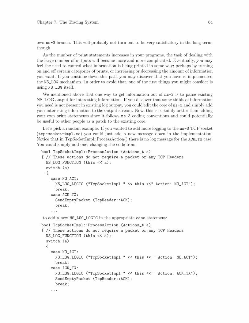
Chapter 7: The Tracing System 64
own ns-3 branch. This will probably not turn out to be very satisfactory in the long term,though.
As the number of print statements increases in your programs, the task of dealing withthe large number of outputs will become more and more complicated. Eventually, you mayfeel the need to control what information is being printed in some way; perhaps by turningon and off certain categories of prints, or increasing or decreasing the amount of informationyou want. If you continue down this path you may discover that you have re-implementedthe NS_LOG mechanism. In order to avoid that, one of the first things you might consider isusing NS_LOG itself.
We mentioned above that one way to get information out of ns-3 is to parse existingNS LOG output for interesting information. If you discover that some tidbit of informationyou need is not present in existing log output, you could edit the core of ns-3 and simply addyour interesting information to the output stream. Now, this is certainly better than addingyour own print statements since it follows ns-3 coding conventions and could potentiallybe useful to other people as a patch to the existing core.
Let’s pick a random example. If you wanted to add more logging to the ns-3 TCP socket(tcp-socket-impl.cc) you could just add a new message down in the implementation.Notice that in TcpSocketImpl::ProcessAction() there is no log message for the ACK_TX case.You could simply add one, changing the code from:
bool TcpSocketImpl::ProcessAction (Actions_t a){ // These actions do not require a packet or any TCP Headers
NS_LOG_FUNCTION (this << a);switch (a){case NO_ACT:
NS_LOG_LOGIC ("TcpSocketImpl " << this <<" Action: NO_ACT");break;
case ACK_TX:SendEmptyPacket (TcpHeader::ACK);break;
...
to add a new NS_LOG_LOGIC in the appropriate case statement:
bool TcpSocketImpl::ProcessAction (Actions_t a){ // These actions do not require a packet or any TCP Headers
NS_LOG_FUNCTION (this << a);switch (a){case NO_ACT:NS_LOG_LOGIC ("TcpSocketImpl " << this << " Action: NO_ACT");break;
case ACK_TX:NS_LOG_LOGIC ("TcpSocketImpl " << this << " Action: ACK_TX");SendEmptyPacket (TcpHeader::ACK);break;
...
Chapter 7: The Tracing System 65
This may seem fairly simple and satisfying at first glance, but something to consideris that you will be writing code to add the NS_LOG statement and you will also have towrite code (as in grep, sed or awk scripts) to parse the log output in order to isolate yourinformation. This is because even though you have some control over what is output by thelogging system, you only have control down to the log component level.
If you are adding code to an existing module, you will also have to live with the outputthat every other developer has found interesting. You may find that in order to get thesmall amount of information you need, you may have to wade through huge amounts ofextraneous messages that are of no interest to you. You may be forced to save huge log filesto disk and process them down to a few lines whenever you want to do anything.
Since there are no guarantees in ns-3 about the stability of NS_LOG messages, you mayalso discover that pieces of log output on which you depend disappear or change betweenreleases. If you depend on the structure of the output, you may find other messages beingadded or deleted which may affect your parsing code.
For these reasons, we consider prints to std::cout and NS LOG messages simple ways toget more information out of ns-3, but they are really unstable and quite blunt instruments.
It is desirable to have a stable facility using stable APIs that allow one to reach intothe core system and only get the information required. It is desirable to be able to do thiswithout having to change and recompile the core system. Even better would be a systemthat notified the user when an item of interest changed or an interesting event happened sothe user doesn’t have to actively go poke around in the system looking for things.
The ns-3 tracing system is designed to work along those lines and is well-integrated withthe Attribute and Config subsystems allowing for relatively simple use scenarios.
7.2 Overview
The ns-3 tracing system is built on the concepts of independent tracing sources and tracingsinks; along with a uniform mechanism for connecting sources to sinks.
Trace sources are entities that can signal events that happen in a simulation and provideaccess to interesting underlying data. For example, a trace source could indicate when apacket is received by a net device and provide access to the packet contents for interestedtrace sinks. A trace source might also indicate when an iteresting state change happens ina model. For example, the congestion window of a TCP model is a prime candidate for atrace source.
Trace sources are not useful by themselves; they must be connected to other pieces ofcode that actually do something useful with the information provided by the source. Theentities that consume trace information are called trace sinks. Trace sources are generatorsof events and trace sinks are consumers. This explicit division allows for large numbersof trace sources to be scattered around the system in places which model authors believemight be useful.
There can be zero or more consumers of trace events generated by a trace source. Onecan think of a trace source as a kind of point-to-multipoint information link. Your codelooking for trace events from a particular piece of core code could happily coexist with othercode doing something entirely different from the same information.
Unless a user connects a trace sink to one of these sources, nothing is output. By usingthe tracing system, both you and other people at the same trace source are getting exactly
Chapter 7: The Tracing System 66
what they want and only what they want out of the system. Neither of you are impactingany other user by changing what information is output by the system. If you happen to adda trace source, your work as a good open-source citizen may allow other users to providenew utilities that are perhaps very useful overall, without making any changes to the ns-3core.
7.2.1 A Simple Low-Level Example
Let’s take a few minutes and walk through a simple tracing example. We are going to needa little background on Callbacks to understand what is happening in the example, so wehave to take a small detour right away.
7.2.1.1 Callbacks
The goal of the Callback system in ns-3 is to allow one piece of code to call a function (ormethod in C++) without any specific inter-module dependency. This ultimately means youneed some kind of indirection – you treat the address of the called function as a variable.This variable is called a pointer-to-function variable. The relationship between function andpointer-to-function pointer is really no different that that of object and pointer-to-object.
In C the canonical example of a pointer-to-function is a pointer-to-function-returning-integer (PFI). For a PFI taking one int parameter, this could be declared like,
int (*pfi)(int arg) = 0;
What you get from this is a variable named simply “pfi” that is initialized to the value 0.If you want to initialize this pointer to something meaningful, you have to have a functionwith a matching signature. In this case, you could provide a function that looks like,
int MyFunction (int arg) {}
If you have this target, you can initialize the variable to point to your function:
pfi = MyFunction;
You can then call MyFunction indirectly using the more suggestive form of the call,
int result = (*pfi) (1234);
This is suggestive since it looks like you are dereferencing the function pointer just likeyou would dereference any pointer. Typically, however, people take advantage of the factthat the compiler knows what is going on and will just use a shorter form,
int result = pfi (1234);
This looks like you are calling a function named “pfi,” but the compiler is smart enoughto know to call through the variable pfi indirectly to the function MyFunction.
Conceptually, this is almost exactly how the tracing system will work. Basically, a tracesource is a callback. When a trace sink expresses interest in receiving trace events, it addsa Callback to a list of Callbacks internally held by the trace source. When an interestingevent happens, the trace source invokes its operator() providing zero or more parameters.The operator() eventually wanders down into the system and does something remarkablylike the indirect call you just saw. It provides zero or more parameters (the call to “pfi”above passed one parameter to the target function MyFunction.
The important difference that the tracing system adds is that for each trace source thereis an internal list of Callbacks. Instead of just making one indirect call, a trace source may
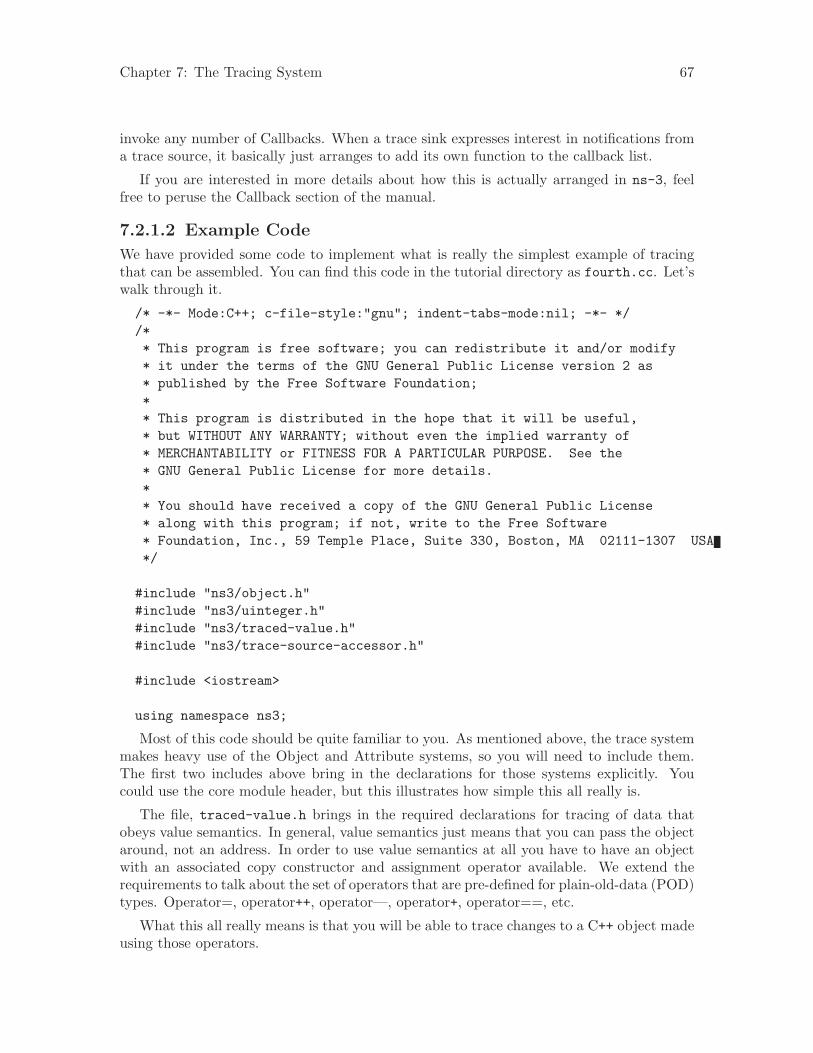
Chapter 7: The Tracing System 67
invoke any number of Callbacks. When a trace sink expresses interest in notifications froma trace source, it basically just arranges to add its own function to the callback list.
If you are interested in more details about how this is actually arranged in ns-3, feelfree to peruse the Callback section of the manual.
7.2.1.2 Example Code
We have provided some code to implement what is really the simplest example of tracingthat can be assembled. You can find this code in the tutorial directory as fourth.cc. Let’swalk through it.
/* -*- Mode:C++; c-file-style:"gnu"; indent-tabs-mode:nil; -*- *//** This program is free software; you can redistribute it and/or modify* it under the terms of the GNU General Public License version 2 as* published by the Free Software Foundation;** This program is distributed in the hope that it will be useful,* but WITHOUT ANY WARRANTY; without even the implied warranty of* MERCHANTABILITY or FITNESS FOR A PARTICULAR PURPOSE. See the* GNU General Public License for more details.** You should have received a copy of the GNU General Public License* along with this program; if not, write to the Free Software* Foundation, Inc., 59 Temple Place, Suite 330, Boston, MA 02111-1307 USA*/
#include "ns3/object.h"#include "ns3/uinteger.h"#include "ns3/traced-value.h"#include "ns3/trace-source-accessor.h"
#include <iostream>
using namespace ns3;
Most of this code should be quite familiar to you. As mentioned above, the trace systemmakes heavy use of the Object and Attribute systems, so you will need to include them.The first two includes above bring in the declarations for those systems explicitly. Youcould use the core module header, but this illustrates how simple this all really is.
The file, traced-value.h brings in the required declarations for tracing of data thatobeys value semantics. In general, value semantics just means that you can pass the objectaround, not an address. In order to use value semantics at all you have to have an objectwith an associated copy constructor and assignment operator available. We extend therequirements to talk about the set of operators that are pre-defined for plain-old-data (POD)types. Operator=, operator++, operator—, operator+, operator==, etc.
What this all really means is that you will be able to trace changes to a C++ object madeusing those operators.
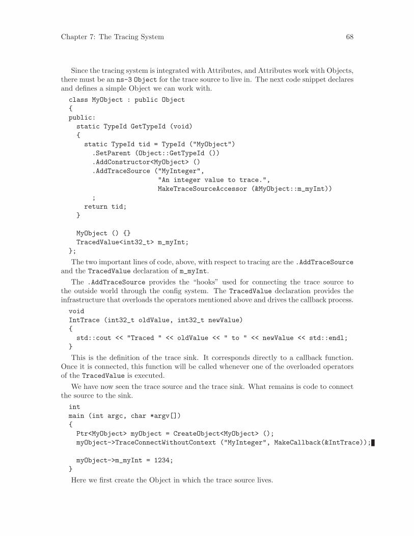
Chapter 7: The Tracing System 68
Since the tracing system is integrated with Attributes, and Attributes work with Objects,there must be an ns-3 Object for the trace source to live in. The next code snippet declaresand defines a simple Object we can work with.class MyObject : public Object{public:
static TypeId GetTypeId (void){static TypeId tid = TypeId ("MyObject")
.SetParent (Object::GetTypeId ())
.AddConstructor<MyObject> ()
.AddTraceSource ("MyInteger","An integer value to trace.",MakeTraceSourceAccessor (&MyObject::m_myInt))
;return tid;
}
MyObject () {}TracedValue<int32_t> m_myInt;
};
The two important lines of code, above, with respect to tracing are the .AddTraceSourceand the TracedValue declaration of m_myInt.
The .AddTraceSource provides the “hooks” used for connecting the trace source tothe outside world through the config system. The TracedValue declaration provides theinfrastructure that overloads the operators mentioned above and drives the callback process.voidIntTrace (int32_t oldValue, int32_t newValue){
std::cout << "Traced " << oldValue << " to " << newValue << std::endl;}
This is the definition of the trace sink. It corresponds directly to a callback function.Once it is connected, this function will be called whenever one of the overloaded operatorsof the TracedValue is executed.
We have now seen the trace source and the trace sink. What remains is code to connectthe source to the sink.intmain (int argc, char *argv[]){
Ptr<MyObject> myObject = CreateObject<MyObject> ();myObject->TraceConnectWithoutContext ("MyInteger", MakeCallback(&IntTrace));
myObject->m_myInt = 1234;}
Here we first create the Object in which the trace source lives.
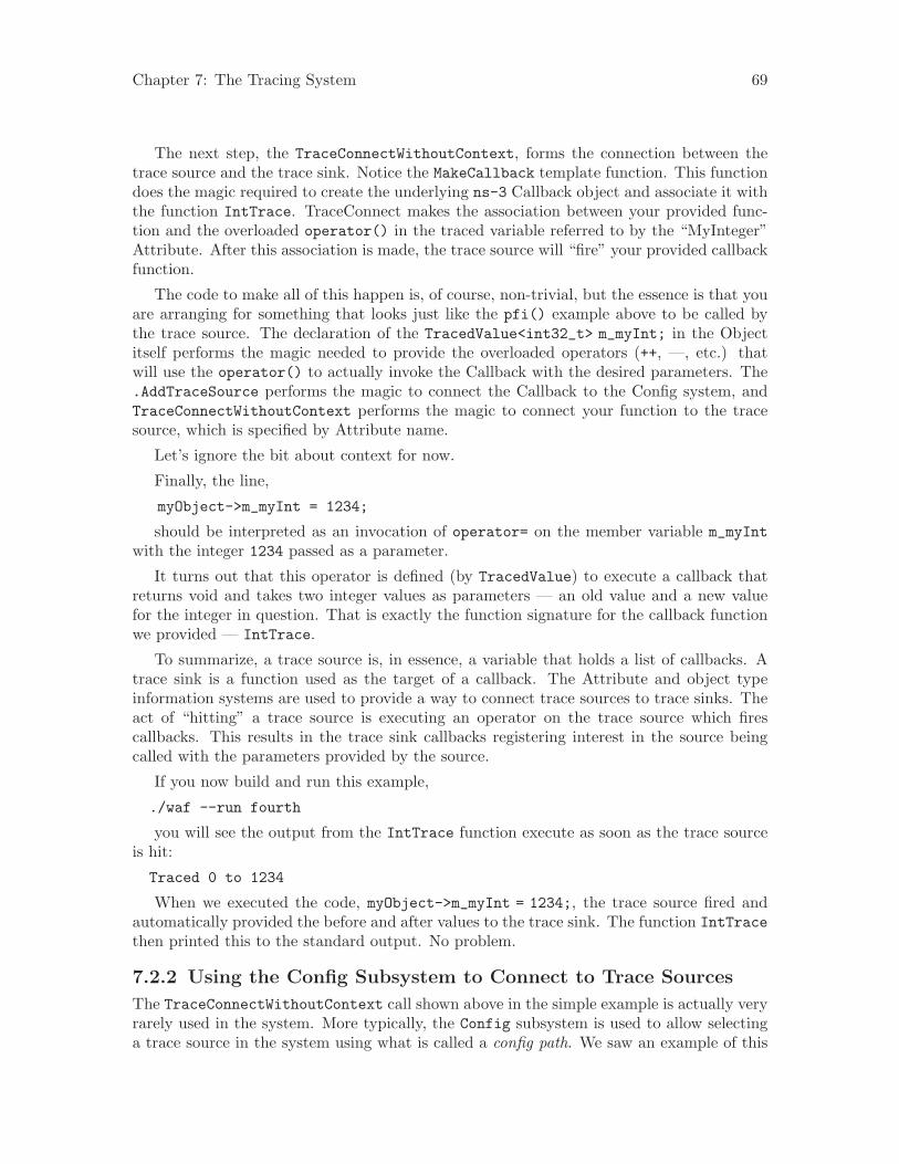
Chapter 7: The Tracing System 69
The next step, the TraceConnectWithoutContext, forms the connection between thetrace source and the trace sink. Notice the MakeCallback template function. This functiondoes the magic required to create the underlying ns-3 Callback object and associate it withthe function IntTrace. TraceConnect makes the association between your provided func-tion and the overloaded operator() in the traced variable referred to by the “MyInteger”Attribute. After this association is made, the trace source will “fire” your provided callbackfunction.
The code to make all of this happen is, of course, non-trivial, but the essence is that youare arranging for something that looks just like the pfi() example above to be called bythe trace source. The declaration of the TracedValue<int32_t> m_myInt; in the Objectitself performs the magic needed to provide the overloaded operators (++, —, etc.) thatwill use the operator() to actually invoke the Callback with the desired parameters. The.AddTraceSource performs the magic to connect the Callback to the Config system, andTraceConnectWithoutContext performs the magic to connect your function to the tracesource, which is specified by Attribute name.
Let’s ignore the bit about context for now.
Finally, the line,
myObject->m_myInt = 1234;
should be interpreted as an invocation of operator= on the member variable m_myIntwith the integer 1234 passed as a parameter.
It turns out that this operator is defined (by TracedValue) to execute a callback thatreturns void and takes two integer values as parameters — an old value and a new valuefor the integer in question. That is exactly the function signature for the callback functionwe provided — IntTrace.
To summarize, a trace source is, in essence, a variable that holds a list of callbacks. Atrace sink is a function used as the target of a callback. The Attribute and object typeinformation systems are used to provide a way to connect trace sources to trace sinks. Theact of “hitting” a trace source is executing an operator on the trace source which firescallbacks. This results in the trace sink callbacks registering interest in the source beingcalled with the parameters provided by the source.
If you now build and run this example,
./waf --run fourth
you will see the output from the IntTrace function execute as soon as the trace sourceis hit:
Traced 0 to 1234
When we executed the code, myObject->m_myInt = 1234;, the trace source fired andautomatically provided the before and after values to the trace sink. The function IntTracethen printed this to the standard output. No problem.
7.2.2 Using the Config Subsystem to Connect to Trace Sources
The TraceConnectWithoutContext call shown above in the simple example is actually veryrarely used in the system. More typically, the Config subsystem is used to allow selectinga trace source in the system using what is called a config path. We saw an example of this
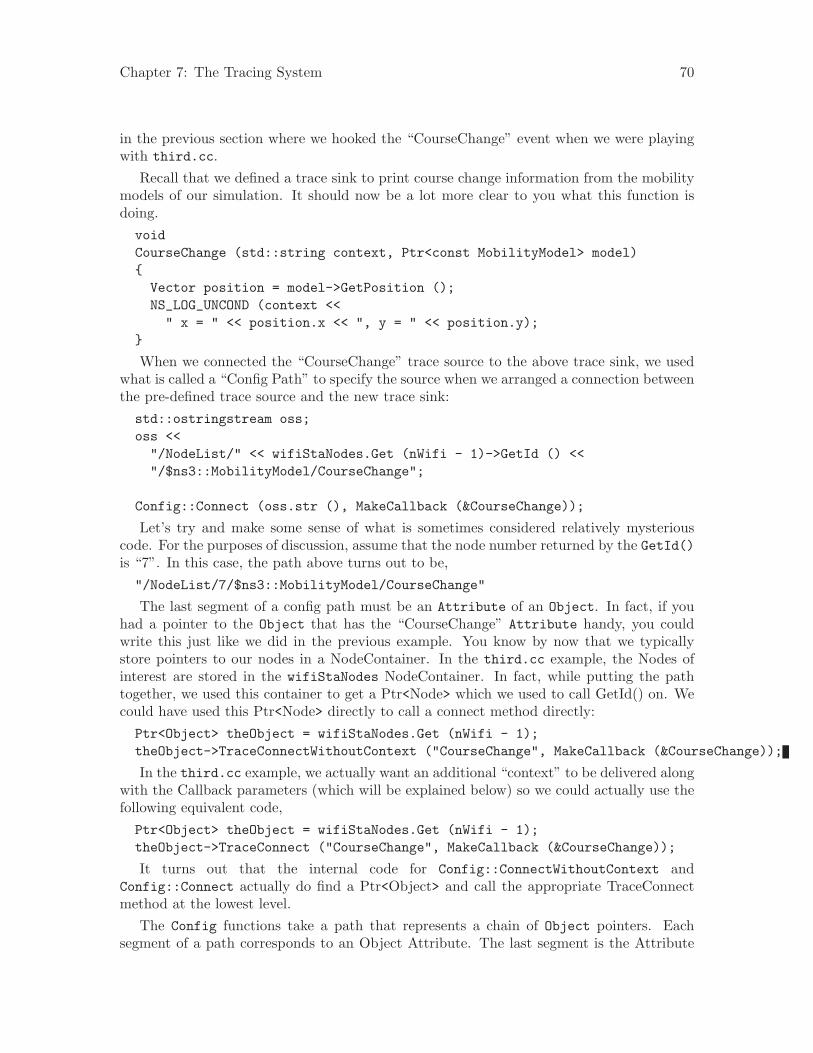
Chapter 7: The Tracing System 70
in the previous section where we hooked the “CourseChange” event when we were playingwith third.cc.
Recall that we defined a trace sink to print course change information from the mobilitymodels of our simulation. It should now be a lot more clear to you what this function isdoing.voidCourseChange (std::string context, Ptr<const MobilityModel> model){
Vector position = model->GetPosition ();NS_LOG_UNCOND (context <<" x = " << position.x << ", y = " << position.y);
}
When we connected the “CourseChange” trace source to the above trace sink, we usedwhat is called a “Config Path” to specify the source when we arranged a connection betweenthe pre-defined trace source and the new trace sink:std::ostringstream oss;oss <<
"/NodeList/" << wifiStaNodes.Get (nWifi - 1)->GetId () <<"/$ns3::MobilityModel/CourseChange";
Config::Connect (oss.str (), MakeCallback (&CourseChange));
Let’s try and make some sense of what is sometimes considered relatively mysteriouscode. For the purposes of discussion, assume that the node number returned by the GetId()is “7”. In this case, the path above turns out to be,"/NodeList/7/$ns3::MobilityModel/CourseChange"
The last segment of a config path must be an Attribute of an Object. In fact, if youhad a pointer to the Object that has the “CourseChange” Attribute handy, you couldwrite this just like we did in the previous example. You know by now that we typicallystore pointers to our nodes in a NodeContainer. In the third.cc example, the Nodes ofinterest are stored in the wifiStaNodes NodeContainer. In fact, while putting the pathtogether, we used this container to get a Ptr<Node> which we used to call GetId() on. Wecould have used this Ptr<Node> directly to call a connect method directly:Ptr<Object> theObject = wifiStaNodes.Get (nWifi - 1);theObject->TraceConnectWithoutContext ("CourseChange", MakeCallback (&CourseChange));
In the third.cc example, we actually want an additional “context” to be delivered alongwith the Callback parameters (which will be explained below) so we could actually use thefollowing equivalent code,Ptr<Object> theObject = wifiStaNodes.Get (nWifi - 1);theObject->TraceConnect ("CourseChange", MakeCallback (&CourseChange));
It turns out that the internal code for Config::ConnectWithoutContext andConfig::Connect actually do find a Ptr<Object> and call the appropriate TraceConnectmethod at the lowest level.
The Config functions take a path that represents a chain of Object pointers. Eachsegment of a path corresponds to an Object Attribute. The last segment is the Attribute
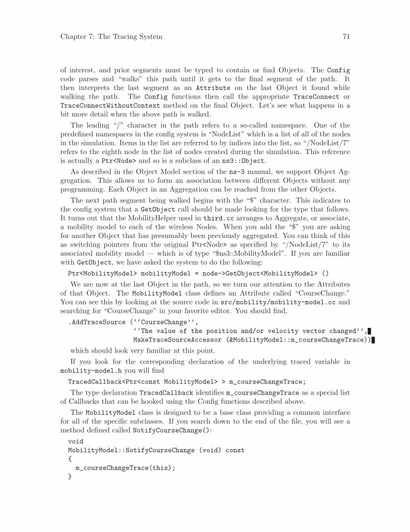
Chapter 7: The Tracing System 71
of interest, and prior segments must be typed to contain or find Objects. The Configcode parses and “walks” this path until it gets to the final segment of the path. Itthen interprets the last segment as an Attribute on the last Object it found whilewalking the path. The Config functions then call the appropriate TraceConnect orTraceConnectWithoutContext method on the final Object. Let’s see what happens in abit more detail when the above path is walked.
The leading “/” character in the path refers to a so-called namespace. One of thepredefined namespaces in the config system is “NodeList” which is a list of all of the nodesin the simulation. Items in the list are referred to by indices into the list, so “/NodeList/7”refers to the eighth node in the list of nodes created during the simulation. This referenceis actually a Ptr<Node> and so is a subclass of an ns3::Object.
As described in the Object Model section of the ns-3 manual, we support Object Ag-gregation. This allows us to form an association between different Objects without anyprogramming. Each Object in an Aggregation can be reached from the other Objects.
The next path segment being walked begins with the “$” character. This indicates tothe config system that a GetObject call should be made looking for the type that follows.It turns out that the MobilityHelper used in third.cc arranges to Aggregate, or associate,a mobility model to each of the wireless Nodes. When you add the “$” you are askingfor another Object that has presumably been previously aggregated. You can think of thisas switching pointers from the original Ptr<Node> as specified by “/NodeList/7” to itsassociated mobility model — which is of type “$ns3::MobilityModel”. If you are familiarwith GetObject, we have asked the system to do the following:Ptr<MobilityModel> mobilityModel = node->GetObject<MobilityModel> ()
We are now at the last Object in the path, so we turn our attention to the Attributesof that Object. The MobilityModel class defines an Attribute called “CourseChange.”You can see this by looking at the source code in src/mobility/mobility-model.cc andsearching for “CourseChange” in your favorite editor. You should find,.AddTraceSource (‘‘CourseChange’’,
‘‘The value of the position and/or velocity vector changed’’,MakeTraceSourceAccessor (&MobilityModel::m_courseChangeTrace))
which should look very familiar at this point.If you look for the corresponding declaration of the underlying traced variable in
mobility-model.h you will findTracedCallback<Ptr<const MobilityModel> > m_courseChangeTrace;
The type declaration TracedCallback identifies m_courseChangeTrace as a special listof Callbacks that can be hooked using the Config functions described above.
The MobilityModel class is designed to be a base class providing a common interfacefor all of the specific subclasses. If you search down to the end of the file, you will see amethod defined called NotifyCourseChange():voidMobilityModel::NotifyCourseChange (void) const{
m_courseChangeTrace(this);}
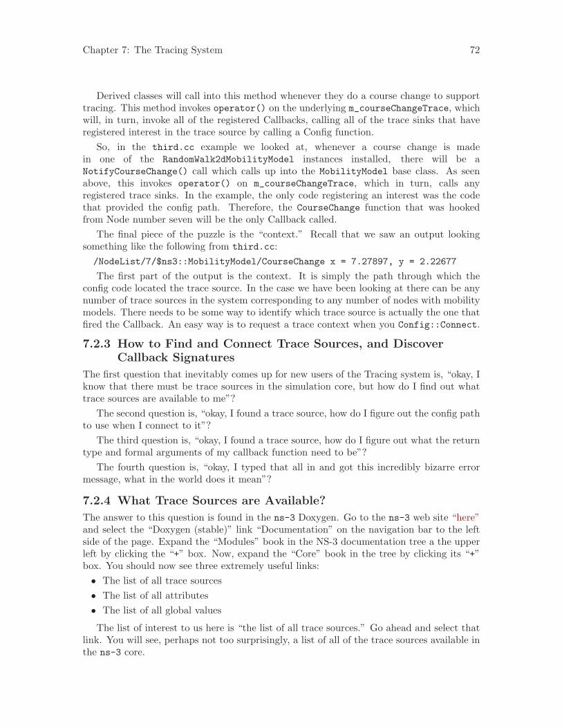
Chapter 7: The Tracing System 72
Derived classes will call into this method whenever they do a course change to supporttracing. This method invokes operator() on the underlying m_courseChangeTrace, whichwill, in turn, invoke all of the registered Callbacks, calling all of the trace sinks that haveregistered interest in the trace source by calling a Config function.
So, in the third.cc example we looked at, whenever a course change is madein one of the RandomWalk2dMobilityModel instances installed, there will be aNotifyCourseChange() call which calls up into the MobilityModel base class. As seenabove, this invokes operator() on m_courseChangeTrace, which in turn, calls anyregistered trace sinks. In the example, the only code registering an interest was the codethat provided the config path. Therefore, the CourseChange function that was hookedfrom Node number seven will be the only Callback called.
The final piece of the puzzle is the “context.” Recall that we saw an output lookingsomething like the following from third.cc:/NodeList/7/$ns3::MobilityModel/CourseChange x = 7.27897, y = 2.22677
The first part of the output is the context. It is simply the path through which theconfig code located the trace source. In the case we have been looking at there can be anynumber of trace sources in the system corresponding to any number of nodes with mobilitymodels. There needs to be some way to identify which trace source is actually the one thatfired the Callback. An easy way is to request a trace context when you Config::Connect.
7.2.3 How to Find and Connect Trace Sources, and DiscoverCallback Signatures
The first question that inevitably comes up for new users of the Tracing system is, “okay, Iknow that there must be trace sources in the simulation core, but how do I find out whattrace sources are available to me”?
The second question is, “okay, I found a trace source, how do I figure out the config pathto use when I connect to it”?
The third question is, “okay, I found a trace source, how do I figure out what the returntype and formal arguments of my callback function need to be”?
The fourth question is, “okay, I typed that all in and got this incredibly bizarre errormessage, what in the world does it mean”?
7.2.4 What Trace Sources are Available?
The answer to this question is found in the ns-3 Doxygen. Go to the ns-3 web site “here”and select the “Doxygen (stable)” link “Documentation” on the navigation bar to the leftside of the page. Expand the “Modules” book in the NS-3 documentation tree a the upperleft by clicking the “+” box. Now, expand the “Core” book in the tree by clicking its “+”box. You should now see three extremely useful links:• The list of all trace sources• The list of all attributes• The list of all global values
The list of interest to us here is “the list of all trace sources.” Go ahead and select thatlink. You will see, perhaps not too surprisingly, a list of all of the trace sources available inthe ns-3 core.
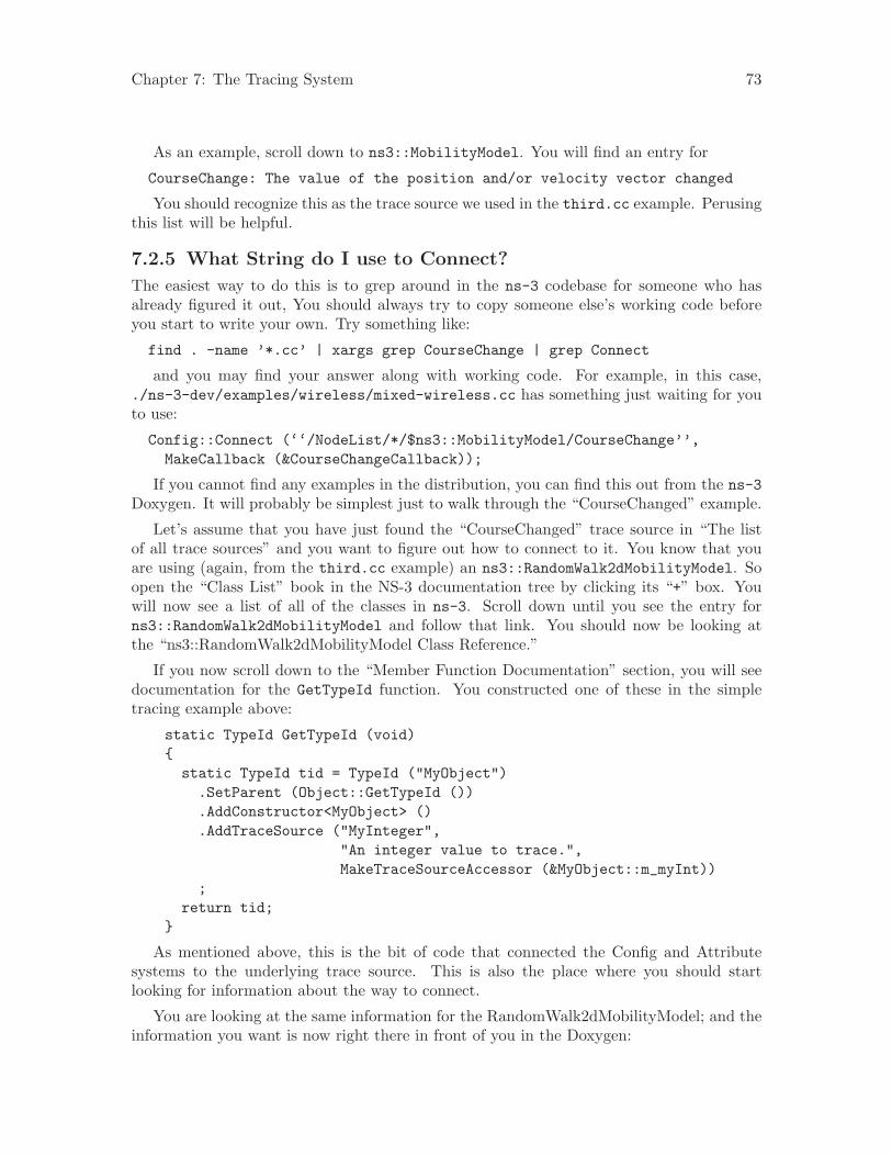
Chapter 7: The Tracing System 73
As an example, scroll down to ns3::MobilityModel. You will find an entry for
CourseChange: The value of the position and/or velocity vector changed
You should recognize this as the trace source we used in the third.cc example. Perusingthis list will be helpful.
7.2.5 What String do I use to Connect?
The easiest way to do this is to grep around in the ns-3 codebase for someone who hasalready figured it out, You should always try to copy someone else’s working code beforeyou start to write your own. Try something like:
find . -name ’*.cc’ | xargs grep CourseChange | grep Connect
and you may find your answer along with working code. For example, in this case,./ns-3-dev/examples/wireless/mixed-wireless.cc has something just waiting for youto use:
Config::Connect (‘‘/NodeList/*/$ns3::MobilityModel/CourseChange’’,MakeCallback (&CourseChangeCallback));
If you cannot find any examples in the distribution, you can find this out from the ns-3Doxygen. It will probably be simplest just to walk through the “CourseChanged” example.
Let’s assume that you have just found the “CourseChanged” trace source in “The listof all trace sources” and you want to figure out how to connect to it. You know that youare using (again, from the third.cc example) an ns3::RandomWalk2dMobilityModel. Soopen the “Class List” book in the NS-3 documentation tree by clicking its “+” box. Youwill now see a list of all of the classes in ns-3. Scroll down until you see the entry forns3::RandomWalk2dMobilityModel and follow that link. You should now be looking atthe “ns3::RandomWalk2dMobilityModel Class Reference.”
If you now scroll down to the “Member Function Documentation” section, you will seedocumentation for the GetTypeId function. You constructed one of these in the simpletracing example above:
static TypeId GetTypeId (void){static TypeId tid = TypeId ("MyObject").SetParent (Object::GetTypeId ()).AddConstructor<MyObject> ().AddTraceSource ("MyInteger",
"An integer value to trace.",MakeTraceSourceAccessor (&MyObject::m_myInt))
;return tid;
}
As mentioned above, this is the bit of code that connected the Config and Attributesystems to the underlying trace source. This is also the place where you should startlooking for information about the way to connect.
You are looking at the same information for the RandomWalk2dMobilityModel; and theinformation you want is now right there in front of you in the Doxygen:
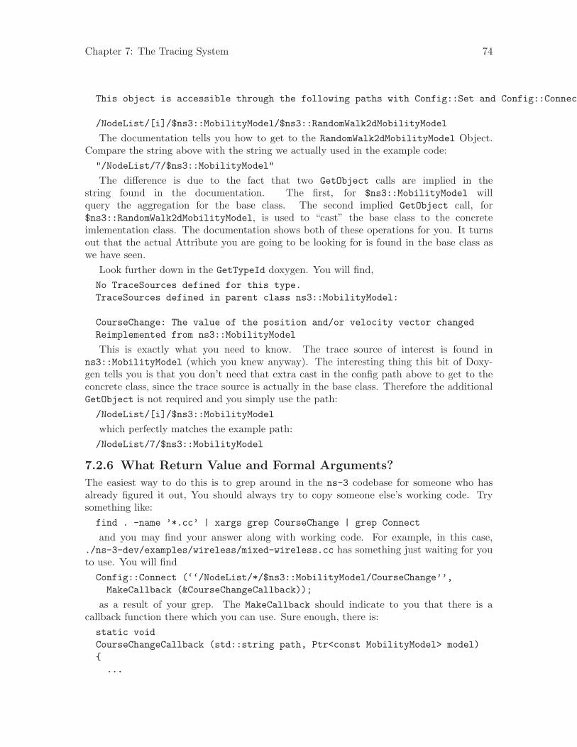
Chapter 7: The Tracing System 74
This object is accessible through the following paths with Config::Set and Config::Connect:
/NodeList/[i]/$ns3::MobilityModel/$ns3::RandomWalk2dMobilityModel
The documentation tells you how to get to the RandomWalk2dMobilityModel Object.Compare the string above with the string we actually used in the example code:"/NodeList/7/$ns3::MobilityModel"
The difference is due to the fact that two GetObject calls are implied in thestring found in the documentation. The first, for $ns3::MobilityModel willquery the aggregation for the base class. The second implied GetObject call, for$ns3::RandomWalk2dMobilityModel, is used to “cast” the base class to the concreteimlementation class. The documentation shows both of these operations for you. It turnsout that the actual Attribute you are going to be looking for is found in the base class aswe have seen.
Look further down in the GetTypeId doxygen. You will find,No TraceSources defined for this type.TraceSources defined in parent class ns3::MobilityModel:
CourseChange: The value of the position and/or velocity vector changedReimplemented from ns3::MobilityModel
This is exactly what you need to know. The trace source of interest is found inns3::MobilityModel (which you knew anyway). The interesting thing this bit of Doxy-gen tells you is that you don’t need that extra cast in the config path above to get to theconcrete class, since the trace source is actually in the base class. Therefore the additionalGetObject is not required and you simply use the path:/NodeList/[i]/$ns3::MobilityModel
which perfectly matches the example path:/NodeList/7/$ns3::MobilityModel
7.2.6 What Return Value and Formal Arguments?
The easiest way to do this is to grep around in the ns-3 codebase for someone who hasalready figured it out, You should always try to copy someone else’s working code. Trysomething like:find . -name ’*.cc’ | xargs grep CourseChange | grep Connect
and you may find your answer along with working code. For example, in this case,./ns-3-dev/examples/wireless/mixed-wireless.cc has something just waiting for youto use. You will findConfig::Connect (‘‘/NodeList/*/$ns3::MobilityModel/CourseChange’’,
MakeCallback (&CourseChangeCallback));
as a result of your grep. The MakeCallback should indicate to you that there is acallback function there which you can use. Sure enough, there is:static voidCourseChangeCallback (std::string path, Ptr<const MobilityModel> model){
...

Chapter 7: The Tracing System 75
}
7.2.6.1 Take my Word for It
If there are no examples to work from, this can be, well, challenging to actually figure outfrom the source code.
Before embarking on a walkthrough of the code, I’ll be kind and just tell you a simpleway to figure this out: The return value of your callback will always be void. The formalparameter list for a TracedCallback can be found from the template parameter list in thedeclaration. Recall that for our current example, this is in mobility-model.h, where wehave previously found:TracedCallback<Ptr<const MobilityModel> > m_courseChangeTrace;
There is a one-to-one correspondence between the template parameter list in the dec-laration and the formal arguments of the callback function. Here, there is one templateparameter, which is a Ptr<const MobilityModel>. This tells you that you need a functionthat returns void and takes a a Ptr<const MobilityModel>. For example,voidCourseChangeCallback (Ptr<const MobilityModel> model){
...}
That’s all you need if you want to Config::ConnectWithoutContext. If you want acontext, you need to Config::Connect and use a Callback function that takes a stringcontext, then the required argument.voidCourseChangeCallback (std::string path, Ptr<const MobilityModel> model){
...}
If you want to ensure that your CourseChangeCallback is only visible in your local file,you can add the keyword static and come up with:static voidCourseChangeCallback (std::string path, Ptr<const MobilityModel> model){
...}
which is exactly what we used in the third.cc example.
7.2.6.2 The Hard Way
This section is entirely optional. It is going to be a bumpy ride, especially for those unfa-miliar with the details of templates. However, if you get through this, you will have a verygood handle on a lot of the ns-3 low level idioms.
So, again, let’s figure out what signature of callback function is required for the “Cour-seChange” Attribute. This is going to be painful, but you only need to do this once. Afteryou get through this, you will be able to just look at a TracedCallback and understand it.
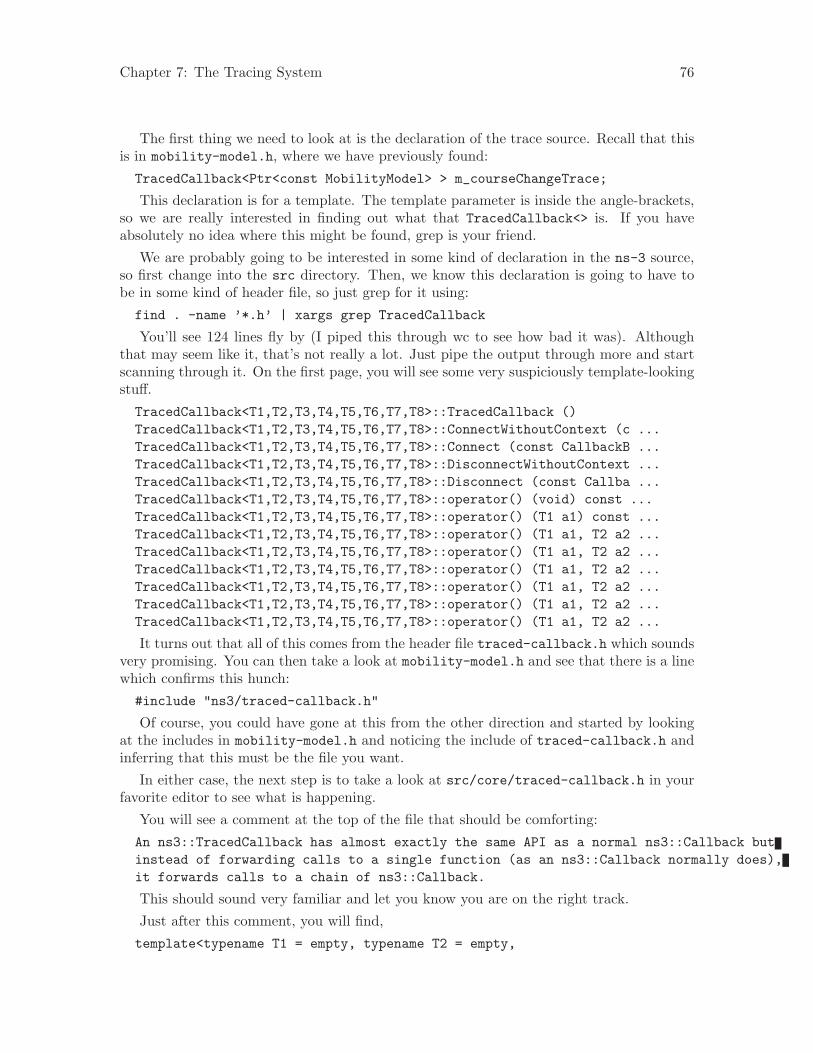
Chapter 7: The Tracing System 76
The first thing we need to look at is the declaration of the trace source. Recall that thisis in mobility-model.h, where we have previously found:
TracedCallback<Ptr<const MobilityModel> > m_courseChangeTrace;
This declaration is for a template. The template parameter is inside the angle-brackets,so we are really interested in finding out what that TracedCallback<> is. If you haveabsolutely no idea where this might be found, grep is your friend.
We are probably going to be interested in some kind of declaration in the ns-3 source,so first change into the src directory. Then, we know this declaration is going to have tobe in some kind of header file, so just grep for it using:
find . -name ’*.h’ | xargs grep TracedCallback
You’ll see 124 lines fly by (I piped this through wc to see how bad it was). Althoughthat may seem like it, that’s not really a lot. Just pipe the output through more and startscanning through it. On the first page, you will see some very suspiciously template-lookingstuff.
TracedCallback<T1,T2,T3,T4,T5,T6,T7,T8>::TracedCallback ()TracedCallback<T1,T2,T3,T4,T5,T6,T7,T8>::ConnectWithoutContext (c ...TracedCallback<T1,T2,T3,T4,T5,T6,T7,T8>::Connect (const CallbackB ...TracedCallback<T1,T2,T3,T4,T5,T6,T7,T8>::DisconnectWithoutContext ...TracedCallback<T1,T2,T3,T4,T5,T6,T7,T8>::Disconnect (const Callba ...TracedCallback<T1,T2,T3,T4,T5,T6,T7,T8>::operator() (void) const ...TracedCallback<T1,T2,T3,T4,T5,T6,T7,T8>::operator() (T1 a1) const ...TracedCallback<T1,T2,T3,T4,T5,T6,T7,T8>::operator() (T1 a1, T2 a2 ...TracedCallback<T1,T2,T3,T4,T5,T6,T7,T8>::operator() (T1 a1, T2 a2 ...TracedCallback<T1,T2,T3,T4,T5,T6,T7,T8>::operator() (T1 a1, T2 a2 ...TracedCallback<T1,T2,T3,T4,T5,T6,T7,T8>::operator() (T1 a1, T2 a2 ...TracedCallback<T1,T2,T3,T4,T5,T6,T7,T8>::operator() (T1 a1, T2 a2 ...TracedCallback<T1,T2,T3,T4,T5,T6,T7,T8>::operator() (T1 a1, T2 a2 ...
It turns out that all of this comes from the header file traced-callback.h which soundsvery promising. You can then take a look at mobility-model.h and see that there is a linewhich confirms this hunch:
#include "ns3/traced-callback.h"
Of course, you could have gone at this from the other direction and started by lookingat the includes in mobility-model.h and noticing the include of traced-callback.h andinferring that this must be the file you want.
In either case, the next step is to take a look at src/core/traced-callback.h in yourfavorite editor to see what is happening.
You will see a comment at the top of the file that should be comforting:
An ns3::TracedCallback has almost exactly the same API as a normal ns3::Callback butinstead of forwarding calls to a single function (as an ns3::Callback normally does),it forwards calls to a chain of ns3::Callback.
This should sound very familiar and let you know you are on the right track.
Just after this comment, you will find,
template<typename T1 = empty, typename T2 = empty,
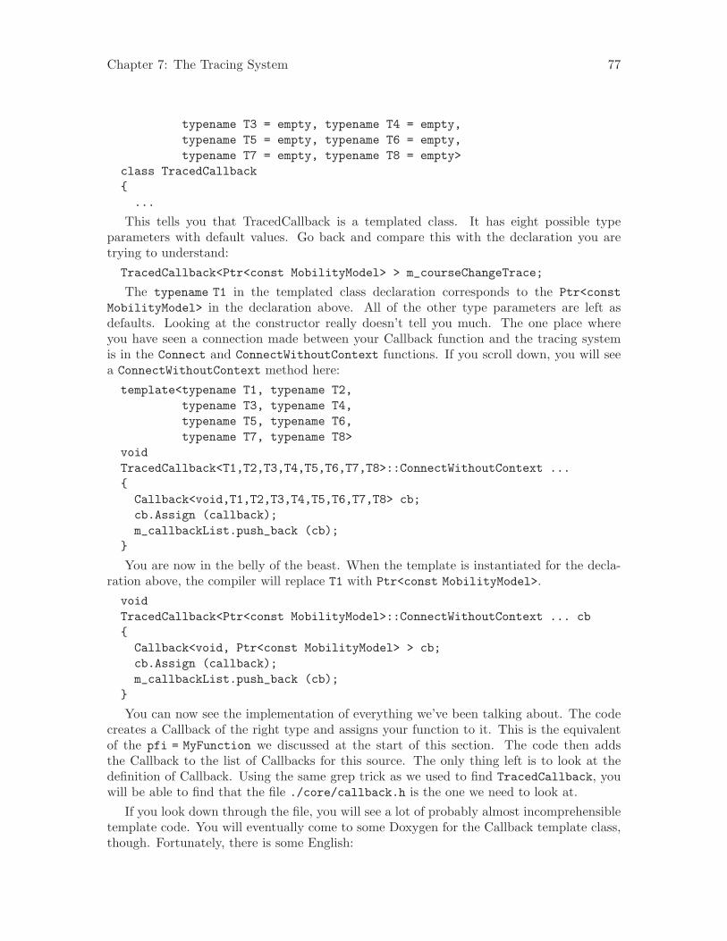
Chapter 7: The Tracing System 77
typename T3 = empty, typename T4 = empty,typename T5 = empty, typename T6 = empty,typename T7 = empty, typename T8 = empty>
class TracedCallback{
...
This tells you that TracedCallback is a templated class. It has eight possible typeparameters with default values. Go back and compare this with the declaration you aretrying to understand:TracedCallback<Ptr<const MobilityModel> > m_courseChangeTrace;
The typename T1 in the templated class declaration corresponds to the Ptr<constMobilityModel> in the declaration above. All of the other type parameters are left asdefaults. Looking at the constructor really doesn’t tell you much. The one place whereyou have seen a connection made between your Callback function and the tracing systemis in the Connect and ConnectWithoutContext functions. If you scroll down, you will seea ConnectWithoutContext method here:template<typename T1, typename T2,
typename T3, typename T4,typename T5, typename T6,typename T7, typename T8>
voidTracedCallback<T1,T2,T3,T4,T5,T6,T7,T8>::ConnectWithoutContext ...{
Callback<void,T1,T2,T3,T4,T5,T6,T7,T8> cb;cb.Assign (callback);m_callbackList.push_back (cb);
}
You are now in the belly of the beast. When the template is instantiated for the decla-ration above, the compiler will replace T1 with Ptr<const MobilityModel>.voidTracedCallback<Ptr<const MobilityModel>::ConnectWithoutContext ... cb{
Callback<void, Ptr<const MobilityModel> > cb;cb.Assign (callback);m_callbackList.push_back (cb);
}
You can now see the implementation of everything we’ve been talking about. The codecreates a Callback of the right type and assigns your function to it. This is the equivalentof the pfi = MyFunction we discussed at the start of this section. The code then addsthe Callback to the list of Callbacks for this source. The only thing left is to look at thedefinition of Callback. Using the same grep trick as we used to find TracedCallback, youwill be able to find that the file ./core/callback.h is the one we need to look at.
If you look down through the file, you will see a lot of probably almost incomprehensibletemplate code. You will eventually come to some Doxygen for the Callback template class,though. Fortunately, there is some English:
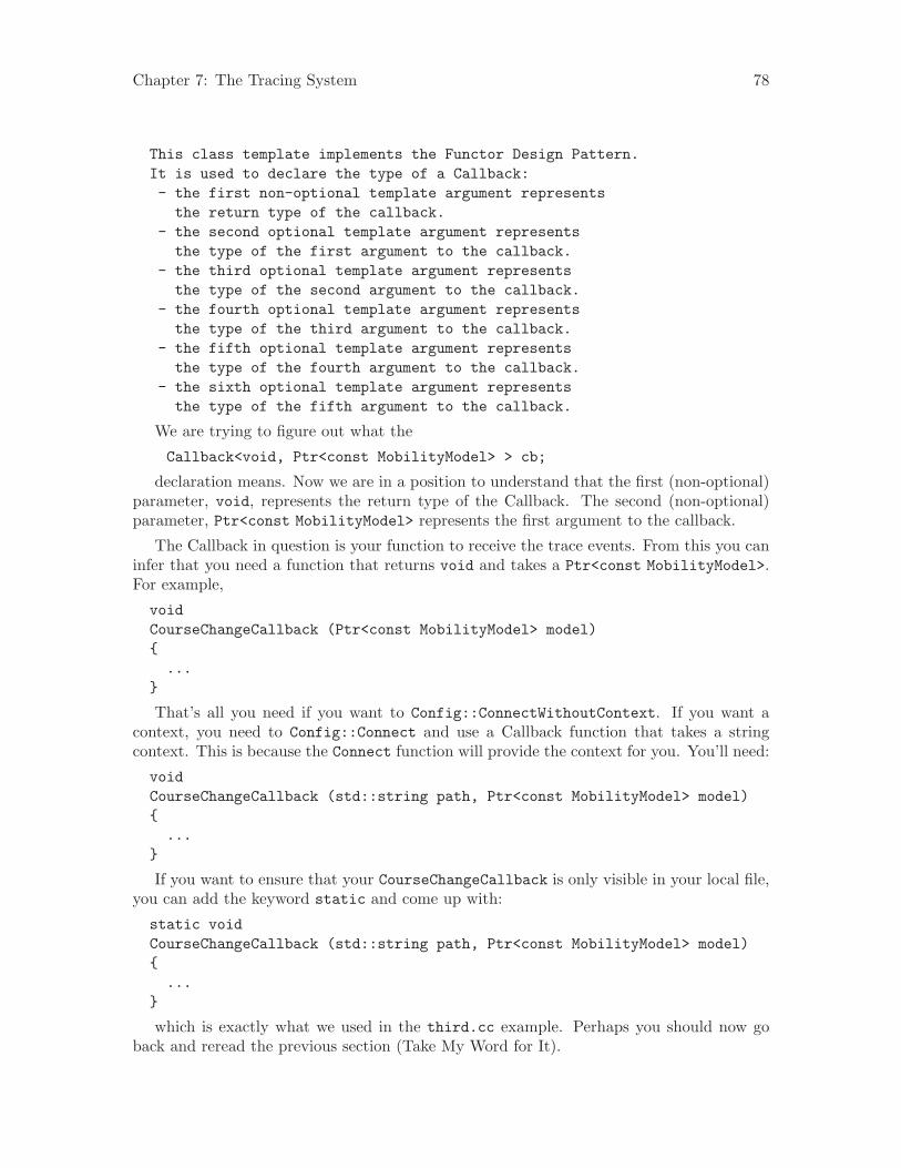
Chapter 7: The Tracing System 78
This class template implements the Functor Design Pattern.It is used to declare the type of a Callback:- the first non-optional template argument representsthe return type of the callback.
- the second optional template argument representsthe type of the first argument to the callback.
- the third optional template argument representsthe type of the second argument to the callback.
- the fourth optional template argument representsthe type of the third argument to the callback.
- the fifth optional template argument representsthe type of the fourth argument to the callback.
- the sixth optional template argument representsthe type of the fifth argument to the callback.
We are trying to figure out what the
Callback<void, Ptr<const MobilityModel> > cb;
declaration means. Now we are in a position to understand that the first (non-optional)parameter, void, represents the return type of the Callback. The second (non-optional)parameter, Ptr<const MobilityModel> represents the first argument to the callback.
The Callback in question is your function to receive the trace events. From this you caninfer that you need a function that returns void and takes a Ptr<const MobilityModel>.For example,
voidCourseChangeCallback (Ptr<const MobilityModel> model){
...}
That’s all you need if you want to Config::ConnectWithoutContext. If you want acontext, you need to Config::Connect and use a Callback function that takes a stringcontext. This is because the Connect function will provide the context for you. You’ll need:
voidCourseChangeCallback (std::string path, Ptr<const MobilityModel> model){
...}
If you want to ensure that your CourseChangeCallback is only visible in your local file,you can add the keyword static and come up with:
static voidCourseChangeCallback (std::string path, Ptr<const MobilityModel> model){
...}
which is exactly what we used in the third.cc example. Perhaps you should now goback and reread the previous section (Take My Word for It).
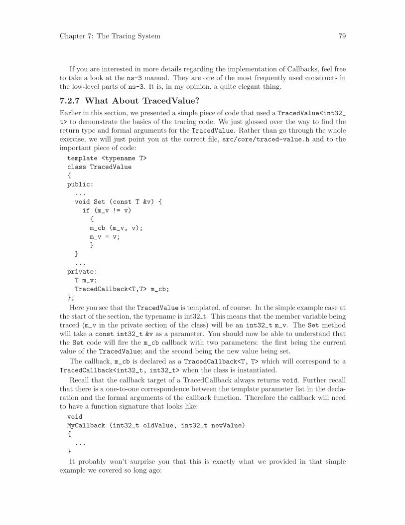
Chapter 7: The Tracing System 79
If you are interested in more details regarding the implementation of Callbacks, feel freeto take a look at the ns-3 manual. They are one of the most frequently used constructs inthe low-level parts of ns-3. It is, in my opinion, a quite elegant thing.
7.2.7 What About TracedValue?
Earlier in this section, we presented a simple piece of code that used a TracedValue<int32_t> to demonstrate the basics of the tracing code. We just glossed over the way to find thereturn type and formal arguments for the TracedValue. Rather than go through the wholeexercise, we will just point you at the correct file, src/core/traced-value.h and to theimportant piece of code:template <typename T>class TracedValue{public:
...void Set (const T &v) {if (m_v != v)
{m_cb (m_v, v);m_v = v;}
}...
private:T m_v;TracedCallback<T,T> m_cb;
};
Here you see that the TracedValue is templated, of course. In the simple example case atthe start of the section, the typename is int32 t. This means that the member variable beingtraced (m_v in the private section of the class) will be an int32_t m_v. The Set methodwill take a const int32_t &v as a parameter. You should now be able to understand thatthe Set code will fire the m_cb callback with two parameters: the first being the currentvalue of the TracedValue; and the second being the new value being set.
The callback, m_cb is declared as a TracedCallback<T, T> which will correspond to aTracedCallback<int32_t, int32_t> when the class is instantiated.
Recall that the callback target of a TracedCallback always returns void. Further recallthat there is a one-to-one correspondence between the template parameter list in the decla-ration and the formal arguments of the callback function. Therefore the callback will needto have a function signature that looks like:voidMyCallback (int32_t oldValue, int32_t newValue){
...}
It probably won’t surprise you that this is exactly what we provided in that simpleexample we covered so long ago:

Chapter 7: The Tracing System 80
voidIntTrace (int32_t oldValue, int32_t newValue){
std::cout << "Traced " << oldValue << " to " << newValue << std::endl;}
7.3 A Real Example
Let’s do an example taken from one of the best-known books on TCP around. “TCP/IPIllustrated, Volume 1: The Protocols,” by W. Richard Stevens is a classic. I just flipped thebook open and ran across a nice plot of both the congestion window and sequence numbersversus time on page 366. Stevens calls this, “Figure 21.10. Value of cwnd and send sequencenumber while data is being transmitted.” Let’s just recreate the cwnd part of that plot inns-3 using the tracing system and gnuplot.
7.3.1 Are There Trace Sources Available?
The first thing to think about is how we want to get the data out. What is it that we needto trace? The first thing to do is to consult “The list of all trace sources” to see what wehave to work with. Recall that this is found in the ns-3 Doxygen in the “Core” Modulesection. If you scroll through the list, you will eventually find:ns3::TcpSocketImplCongestionWindow: The TCP connection’s congestion window
It turns out that the ns-3 TCP implementation lives (mostly) in the file src/internet-stack/tcp-socket-impl.cc. If you don’t know this a priori, you can use the recursive greptrick:find . -name ’*.cc’ | xargs grep -i tcp
You will find page after page of instances of tcp pointing you to that file.If you open src/internet-stack/tcp-socket-impl.cc in your favorite editor, you will
see right up at the top of the file, the following declarations:TypeIdTcpSocketImpl::GetTypeId (){
static TypeId tid = TypeId(‘‘ns3::TcpSocketImpl’’).SetParent<TcpSocket> ().AddTraceSource (‘‘CongestionWindow’’,
‘‘The TCP connection’s congestion window’’,MakeTraceSourceAccessor (&TcpSocketImpl::m_cWnd))
;return tid;
}
This should tell you to look for the declaration of m_cWnd in the header filesrc/internet-stack/tcp-socket-impl.h. If you open this file in your favorite editor,you will find:TracedValue<uint32_t> m_cWnd; //Congestion window
You should now understand this code completely. If we have a pointer to theTcpSocketImpl, we can TraceConnect to the “CongestionWindow” trace source if we
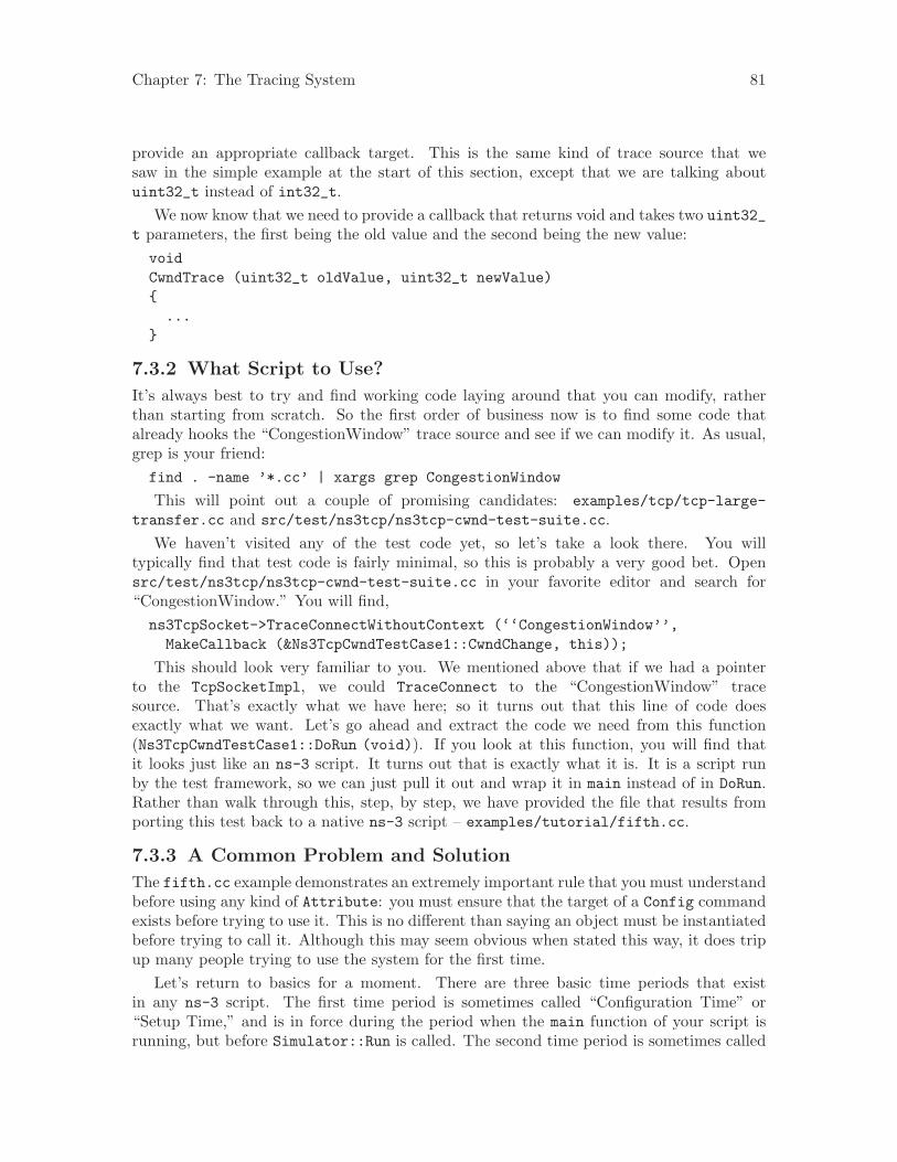
Chapter 7: The Tracing System 81
provide an appropriate callback target. This is the same kind of trace source that wesaw in the simple example at the start of this section, except that we are talking aboutuint32_t instead of int32_t.
We now know that we need to provide a callback that returns void and takes two uint32_t parameters, the first being the old value and the second being the new value:voidCwndTrace (uint32_t oldValue, uint32_t newValue){
...}
7.3.2 What Script to Use?
It’s always best to try and find working code laying around that you can modify, ratherthan starting from scratch. So the first order of business now is to find some code thatalready hooks the “CongestionWindow” trace source and see if we can modify it. As usual,grep is your friend:find . -name ’*.cc’ | xargs grep CongestionWindow
This will point out a couple of promising candidates: examples/tcp/tcp-large-transfer.cc and src/test/ns3tcp/ns3tcp-cwnd-test-suite.cc.
We haven’t visited any of the test code yet, so let’s take a look there. You willtypically find that test code is fairly minimal, so this is probably a very good bet. Opensrc/test/ns3tcp/ns3tcp-cwnd-test-suite.cc in your favorite editor and search for“CongestionWindow.” You will find,ns3TcpSocket->TraceConnectWithoutContext (‘‘CongestionWindow’’,
MakeCallback (&Ns3TcpCwndTestCase1::CwndChange, this));
This should look very familiar to you. We mentioned above that if we had a pointerto the TcpSocketImpl, we could TraceConnect to the “CongestionWindow” tracesource. That’s exactly what we have here; so it turns out that this line of code doesexactly what we want. Let’s go ahead and extract the code we need from this function(Ns3TcpCwndTestCase1::DoRun (void)). If you look at this function, you will find thatit looks just like an ns-3 script. It turns out that is exactly what it is. It is a script runby the test framework, so we can just pull it out and wrap it in main instead of in DoRun.Rather than walk through this, step, by step, we have provided the file that results fromporting this test back to a native ns-3 script – examples/tutorial/fifth.cc.
7.3.3 A Common Problem and Solution
The fifth.cc example demonstrates an extremely important rule that you must understandbefore using any kind of Attribute: you must ensure that the target of a Config commandexists before trying to use it. This is no different than saying an object must be instantiatedbefore trying to call it. Although this may seem obvious when stated this way, it does tripup many people trying to use the system for the first time.
Let’s return to basics for a moment. There are three basic time periods that existin any ns-3 script. The first time period is sometimes called “Configuration Time” or“Setup Time,” and is in force during the period when the main function of your script isrunning, but before Simulator::Run is called. The second time period is sometimes called
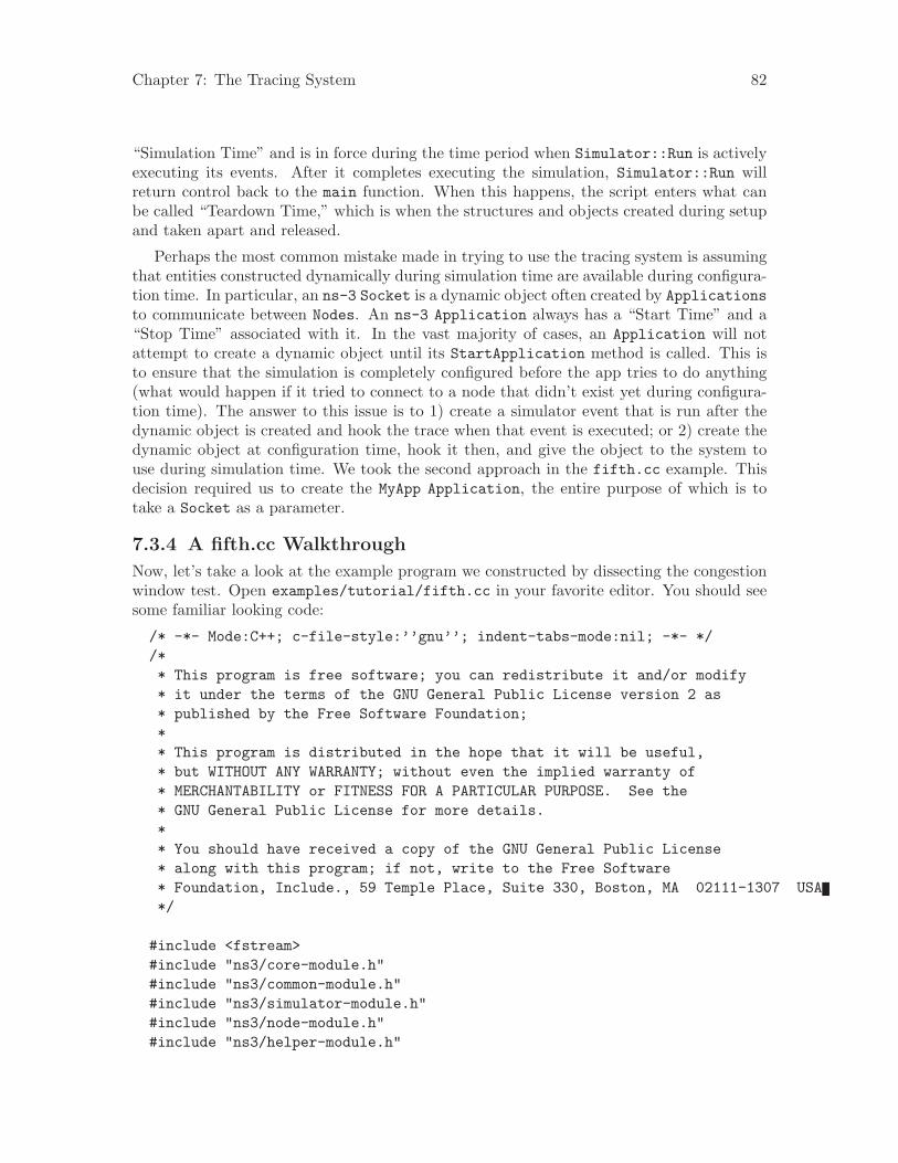
Chapter 7: The Tracing System 82
“Simulation Time” and is in force during the time period when Simulator::Run is activelyexecuting its events. After it completes executing the simulation, Simulator::Run willreturn control back to the main function. When this happens, the script enters what canbe called “Teardown Time,” which is when the structures and objects created during setupand taken apart and released.
Perhaps the most common mistake made in trying to use the tracing system is assumingthat entities constructed dynamically during simulation time are available during configura-tion time. In particular, an ns-3 Socket is a dynamic object often created by Applicationsto communicate between Nodes. An ns-3 Application always has a “Start Time” and a“Stop Time” associated with it. In the vast majority of cases, an Application will notattempt to create a dynamic object until its StartApplication method is called. This isto ensure that the simulation is completely configured before the app tries to do anything(what would happen if it tried to connect to a node that didn’t exist yet during configura-tion time). The answer to this issue is to 1) create a simulator event that is run after thedynamic object is created and hook the trace when that event is executed; or 2) create thedynamic object at configuration time, hook it then, and give the object to the system touse during simulation time. We took the second approach in the fifth.cc example. Thisdecision required us to create the MyApp Application, the entire purpose of which is totake a Socket as a parameter.
7.3.4 A fifth.cc Walkthrough
Now, let’s take a look at the example program we constructed by dissecting the congestionwindow test. Open examples/tutorial/fifth.cc in your favorite editor. You should seesome familiar looking code:
/* -*- Mode:C++; c-file-style:’’gnu’’; indent-tabs-mode:nil; -*- *//** This program is free software; you can redistribute it and/or modify* it under the terms of the GNU General Public License version 2 as* published by the Free Software Foundation;** This program is distributed in the hope that it will be useful,* but WITHOUT ANY WARRANTY; without even the implied warranty of* MERCHANTABILITY or FITNESS FOR A PARTICULAR PURPOSE. See the* GNU General Public License for more details.** You should have received a copy of the GNU General Public License* along with this program; if not, write to the Free Software* Foundation, Include., 59 Temple Place, Suite 330, Boston, MA 02111-1307 USA*/
#include <fstream>#include "ns3/core-module.h"#include "ns3/common-module.h"#include "ns3/simulator-module.h"#include "ns3/node-module.h"#include "ns3/helper-module.h"

Chapter 7: The Tracing System 83
using namespace ns3;
NS_LOG_COMPONENT_DEFINE ("FifthScriptExample");
This has all been covered, so we won’t rehash it. The next lines of source are the networkillustration and a comment addressing the problem described above with Socket.// ===========================================================================//// node 0 node 1// +----------------+ +----------------+// | ns-3 TCP | | ns-3 TCP |// +----------------+ +----------------+// | 10.1.1.1 | | 10.1.1.2 |// +----------------+ +----------------+// | point-to-point | | point-to-point |// +----------------+ +----------------+// | |// +---------------------+// 5 Mbps, 2 ms////// We want to look at changes in the ns-3 TCP congestion window. We need// to crank up a flow and hook the CongestionWindow attribute on the socket// of the sender. Normally one would use an on-off application to generate a// flow, but this has a couple of problems. First, the socket of the on-off// application is not created until Application Start time, so we wouldn’t be// able to hook the socket (now) at configuration time. Second, even if we// could arrange a call after start time, the socket is not public so we// couldn’t get at it.//// So, we can cook up a simple version of the on-off application that does what// we want. On the plus side we don’t need all of the complexity of the on-off// application. On the minus side, we don’t have a helper, so we have to get// a little more involved in the details, but this is trivial.//// So first, we create a socket and do the trace connect on it; then we pass// this socket into the constructor of our simple application which we then// install in the source node.// ===========================================================================//
This should also be self-explanatory.The next part is the declaration of the MyApp Application that we put together to allow
the Socket to be created at configuration time.class MyApp : public Application{public:
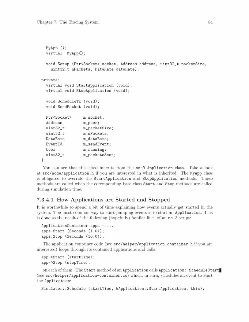
Chapter 7: The Tracing System 84
MyApp ();virtual ~MyApp();
void Setup (Ptr<Socket> socket, Address address, uint32_t packetSize,uint32_t nPackets, DataRate dataRate);
private:virtual void StartApplication (void);virtual void StopApplication (void);
void ScheduleTx (void);void SendPacket (void);
Ptr<Socket> m_socket;Address m_peer;uint32_t m_packetSize;uint32_t m_nPackets;DataRate m_dataRate;EventId m_sendEvent;bool m_running;uint32_t m_packetsSent;
};
You can see that this class inherits from the ns-3 Application class. Take a lookat src/node/application.h if you are interested in what is inherited. The MyApp classis obligated to override the StartApplication and StopApplication methods. Thesemethods are called when the corresponding base class Start and Stop methods are calledduring simulation time.
7.3.4.1 How Applications are Started and Stopped
It is worthwhile to spend a bit of time explaining how events actually get started in thesystem. The most common way to start pumping events is to start an Application. Thisis done as the result of the following (hopefully) familar lines of an ns-3 script:
ApplicationContainer apps = ...apps.Start (Seconds (1.0));apps.Stop (Seconds (10.0));
The application container code (see src/helper/application-container.h if you areinterested) loops through its contained applications and calls,
app->Start (startTime);app->Stop (stopTime);
on each of them. The Start method of an Application calls Application::ScheduleStart(see src/helper/application-container.cc) which, in turn, schedules an event to startthe Application:
Simulator::Schedule (startTime, &Application::StartApplication, this);
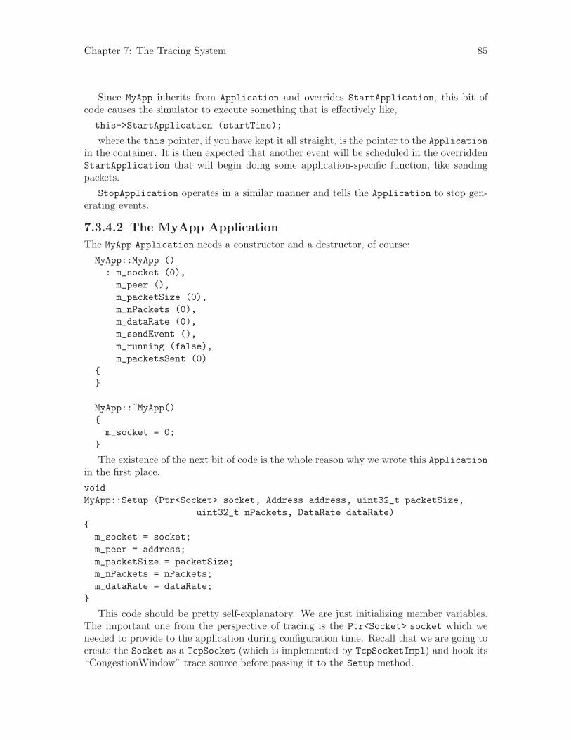
Chapter 7: The Tracing System 85
Since MyApp inherits from Application and overrides StartApplication, this bit ofcode causes the simulator to execute something that is effectively like,this->StartApplication (startTime);
where the this pointer, if you have kept it all straight, is the pointer to the Applicationin the container. It is then expected that another event will be scheduled in the overriddenStartApplication that will begin doing some application-specific function, like sendingpackets.
StopApplication operates in a similar manner and tells the Application to stop gen-erating events.
7.3.4.2 The MyApp Application
The MyApp Application needs a constructor and a destructor, of course:MyApp::MyApp ()
: m_socket (0),m_peer (),m_packetSize (0),m_nPackets (0),m_dataRate (0),m_sendEvent (),m_running (false),m_packetsSent (0)
{}
MyApp::~MyApp(){
m_socket = 0;}
The existence of the next bit of code is the whole reason why we wrote this Applicationin the first place.voidMyApp::Setup (Ptr<Socket> socket, Address address, uint32_t packetSize,
uint32_t nPackets, DataRate dataRate){m_socket = socket;m_peer = address;m_packetSize = packetSize;m_nPackets = nPackets;m_dataRate = dataRate;
}
This code should be pretty self-explanatory. We are just initializing member variables.The important one from the perspective of tracing is the Ptr<Socket> socket which weneeded to provide to the application during configuration time. Recall that we are going tocreate the Socket as a TcpSocket (which is implemented by TcpSocketImpl) and hook its“CongestionWindow” trace source before passing it to the Setup method.
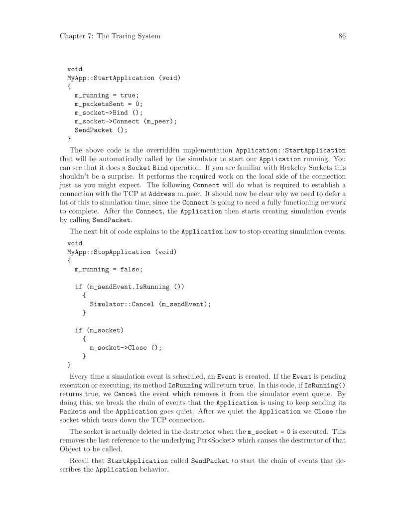
Chapter 7: The Tracing System 86
voidMyApp::StartApplication (void){
m_running = true;m_packetsSent = 0;m_socket->Bind ();m_socket->Connect (m_peer);SendPacket ();
}
The above code is the overridden implementation Application::StartApplicationthat will be automatically called by the simulator to start our Application running. Youcan see that it does a Socket Bind operation. If you are familiar with Berkeley Sockets thisshouldn’t be a surprise. It performs the required work on the local side of the connectionjust as you might expect. The following Connect will do what is required to establish aconnection with the TCP at Address m peer. It should now be clear why we need to defer alot of this to simulation time, since the Connect is going to need a fully functioning networkto complete. After the Connect, the Application then starts creating simulation eventsby calling SendPacket.
The next bit of code explains to the Application how to stop creating simulation events.
voidMyApp::StopApplication (void){
m_running = false;
if (m_sendEvent.IsRunning ()){Simulator::Cancel (m_sendEvent);
}
if (m_socket){
m_socket->Close ();}
}
Every time a simulation event is scheduled, an Event is created. If the Event is pendingexecution or executing, its method IsRunning will return true. In this code, if IsRunning()returns true, we Cancel the event which removes it from the simulator event queue. Bydoing this, we break the chain of events that the Application is using to keep sending itsPackets and the Application goes quiet. After we quiet the Application we Close thesocket which tears down the TCP connection.
The socket is actually deleted in the destructor when the m_socket = 0 is executed. Thisremoves the last reference to the underlying Ptr<Socket> which causes the destructor of thatObject to be called.
Recall that StartApplication called SendPacket to start the chain of events that de-scribes the Application behavior.
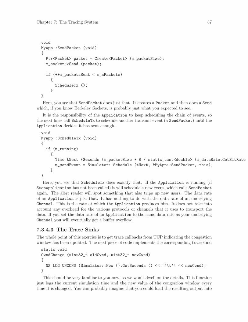
Chapter 7: The Tracing System 87
voidMyApp::SendPacket (void){
Ptr<Packet> packet = Create<Packet> (m_packetSize);m_socket->Send (packet);
if (++m_packetsSent < m_nPackets){
ScheduleTx ();}
}
Here, you see that SendPacket does just that. It creates a Packet and then does a Sendwhich, if you know Berkeley Sockets, is probably just what you expected to see.
It is the responsibility of the Application to keep scheduling the chain of events, sothe next lines call ScheduleTx to schedule another transmit event (a SendPacket) until theApplication decides it has sent enough.
voidMyApp::ScheduleTx (void){
if (m_running){
Time tNext (Seconds (m_packetSize * 8 / static_cast<double> (m_dataRate.GetBitRate ())));m_sendEvent = Simulator::Schedule (tNext, &MyApp::SendPacket, this);
}}
Here, you see that ScheduleTx does exactly that. If the Applciation is running (ifStopApplication has not been called) it will schedule a new event, which calls SendPacketagain. The alert reader will spot something that also trips up new users. The data rateof an Application is just that. It has nothing to do with the data rate of an underlyingChannel. This is the rate at which the Application produces bits. It does not take intoaccount any overhead for the various protocols or channels that it uses to transport thedata. If you set the data rate of an Application to the same data rate as your underlyingChannel you will eventually get a buffer overflow.
7.3.4.3 The Trace Sinks
The whole point of this exercise is to get trace callbacks from TCP indicating the congestionwindow has been updated. The next piece of code implements the corresponding trace sink:
static voidCwndChange (uint32_t oldCwnd, uint32_t newCwnd){
NS_LOG_UNCOND (Simulator::Now ().GetSeconds () << ‘‘\t’’ << newCwnd);}
This should be very familiar to you now, so we won’t dwell on the details. This functionjust logs the current simulation time and the new value of the congestion window everytime it is changed. You can probably imagine that you could load the resulting output into
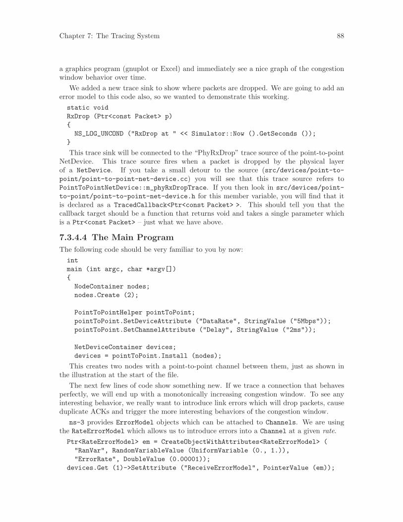
Chapter 7: The Tracing System 88
a graphics program (gnuplot or Excel) and immediately see a nice graph of the congestionwindow behavior over time.
We added a new trace sink to show where packets are dropped. We are going to add anerror model to this code also, so we wanted to demonstrate this working.static voidRxDrop (Ptr<const Packet> p){
NS_LOG_UNCOND ("RxDrop at " << Simulator::Now ().GetSeconds ());}
This trace sink will be connected to the “PhyRxDrop” trace source of the point-to-pointNetDevice. This trace source fires when a packet is dropped by the physical layerof a NetDevice. If you take a small detour to the source (src/devices/point-to-point/point-to-point-net-device.cc) you will see that this trace source refers toPointToPointNetDevice::m_phyRxDropTrace. If you then look in src/devices/point-to-point/point-to-point-net-device.h for this member variable, you will find that itis declared as a TracedCallback<Ptr<const Packet> >. This should tell you that thecallback target should be a function that returns void and takes a single parameter whichis a Ptr<const Packet> – just what we have above.
7.3.4.4 The Main Program
The following code should be very familiar to you by now:intmain (int argc, char *argv[]){
NodeContainer nodes;nodes.Create (2);
PointToPointHelper pointToPoint;pointToPoint.SetDeviceAttribute ("DataRate", StringValue ("5Mbps"));pointToPoint.SetChannelAttribute ("Delay", StringValue ("2ms"));
NetDeviceContainer devices;devices = pointToPoint.Install (nodes);
This creates two nodes with a point-to-point channel between them, just as shown inthe illustration at the start of the file.
The next few lines of code show something new. If we trace a connection that behavesperfectly, we will end up with a monotonically increasing congestion window. To see anyinteresting behavior, we really want to introduce link errors which will drop packets, causeduplicate ACKs and trigger the more interesting behaviors of the congestion window.
ns-3 provides ErrorModel objects which can be attached to Channels. We are usingthe RateErrorModel which allows us to introduce errors into a Channel at a given rate.Ptr<RateErrorModel> em = CreateObjectWithAttributes<RateErrorModel> (
"RanVar", RandomVariableValue (UniformVariable (0., 1.)),"ErrorRate", DoubleValue (0.00001));
devices.Get (1)->SetAttribute ("ReceiveErrorModel", PointerValue (em));
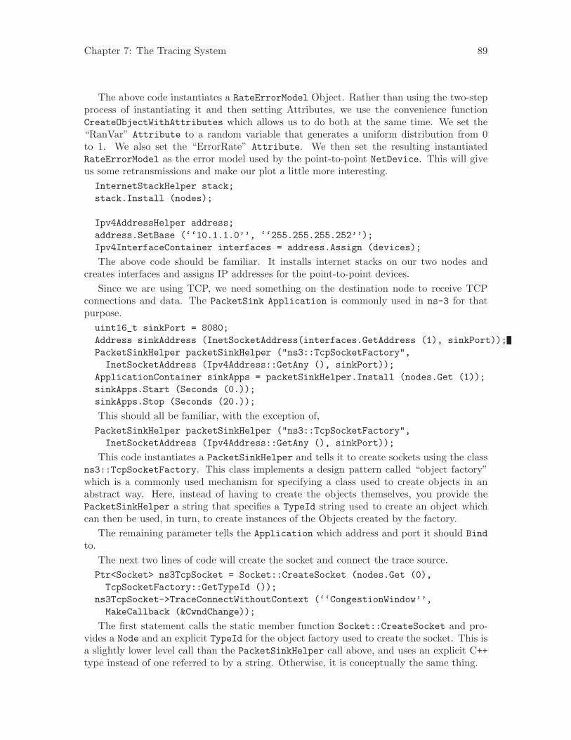
Chapter 7: The Tracing System 89
The above code instantiates a RateErrorModel Object. Rather than using the two-stepprocess of instantiating it and then setting Attributes, we use the convenience functionCreateObjectWithAttributes which allows us to do both at the same time. We set the“RanVar” Attribute to a random variable that generates a uniform distribution from 0to 1. We also set the “ErrorRate” Attribute. We then set the resulting instantiatedRateErrorModel as the error model used by the point-to-point NetDevice. This will giveus some retransmissions and make our plot a little more interesting.InternetStackHelper stack;stack.Install (nodes);
Ipv4AddressHelper address;address.SetBase (‘‘10.1.1.0’’, ‘‘255.255.255.252’’);Ipv4InterfaceContainer interfaces = address.Assign (devices);
The above code should be familiar. It installs internet stacks on our two nodes andcreates interfaces and assigns IP addresses for the point-to-point devices.
Since we are using TCP, we need something on the destination node to receive TCPconnections and data. The PacketSink Application is commonly used in ns-3 for thatpurpose.uint16_t sinkPort = 8080;Address sinkAddress (InetSocketAddress(interfaces.GetAddress (1), sinkPort));PacketSinkHelper packetSinkHelper ("ns3::TcpSocketFactory",
InetSocketAddress (Ipv4Address::GetAny (), sinkPort));ApplicationContainer sinkApps = packetSinkHelper.Install (nodes.Get (1));sinkApps.Start (Seconds (0.));sinkApps.Stop (Seconds (20.));
This should all be familiar, with the exception of,PacketSinkHelper packetSinkHelper ("ns3::TcpSocketFactory",
InetSocketAddress (Ipv4Address::GetAny (), sinkPort));
This code instantiates a PacketSinkHelper and tells it to create sockets using the classns3::TcpSocketFactory. This class implements a design pattern called “object factory”which is a commonly used mechanism for specifying a class used to create objects in anabstract way. Here, instead of having to create the objects themselves, you provide thePacketSinkHelper a string that specifies a TypeId string used to create an object whichcan then be used, in turn, to create instances of the Objects created by the factory.
The remaining parameter tells the Application which address and port it should Bindto.
The next two lines of code will create the socket and connect the trace source.Ptr<Socket> ns3TcpSocket = Socket::CreateSocket (nodes.Get (0),
TcpSocketFactory::GetTypeId ());ns3TcpSocket->TraceConnectWithoutContext (‘‘CongestionWindow’’,
MakeCallback (&CwndChange));
The first statement calls the static member function Socket::CreateSocket and pro-vides a Node and an explicit TypeId for the object factory used to create the socket. This isa slightly lower level call than the PacketSinkHelper call above, and uses an explicit C++type instead of one referred to by a string. Otherwise, it is conceptually the same thing.
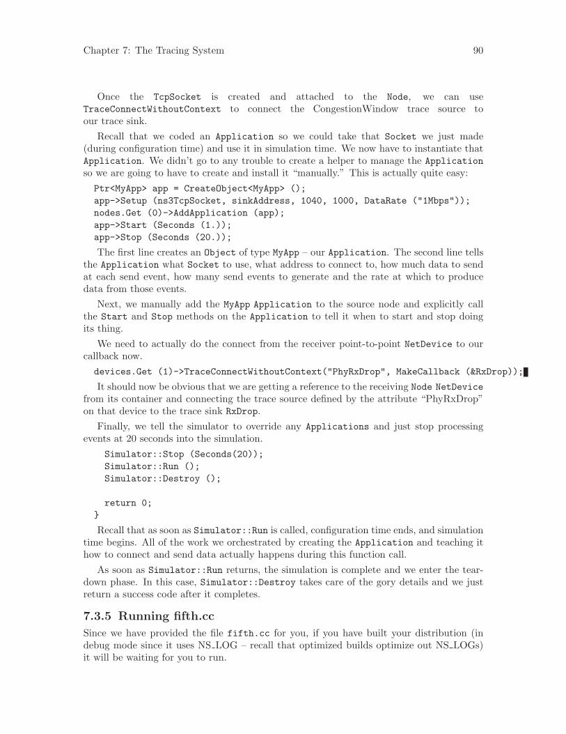
Chapter 7: The Tracing System 90
Once the TcpSocket is created and attached to the Node, we can useTraceConnectWithoutContext to connect the CongestionWindow trace source toour trace sink.
Recall that we coded an Application so we could take that Socket we just made(during configuration time) and use it in simulation time. We now have to instantiate thatApplication. We didn’t go to any trouble to create a helper to manage the Applicationso we are going to have to create and install it “manually.” This is actually quite easy:Ptr<MyApp> app = CreateObject<MyApp> ();app->Setup (ns3TcpSocket, sinkAddress, 1040, 1000, DataRate ("1Mbps"));nodes.Get (0)->AddApplication (app);app->Start (Seconds (1.));app->Stop (Seconds (20.));
The first line creates an Object of type MyApp – our Application. The second line tellsthe Application what Socket to use, what address to connect to, how much data to sendat each send event, how many send events to generate and the rate at which to producedata from those events.
Next, we manually add the MyApp Application to the source node and explicitly callthe Start and Stop methods on the Application to tell it when to start and stop doingits thing.
We need to actually do the connect from the receiver point-to-point NetDevice to ourcallback now.devices.Get (1)->TraceConnectWithoutContext("PhyRxDrop", MakeCallback (&RxDrop));
It should now be obvious that we are getting a reference to the receiving Node NetDevicefrom its container and connecting the trace source defined by the attribute “PhyRxDrop”on that device to the trace sink RxDrop.
Finally, we tell the simulator to override any Applications and just stop processingevents at 20 seconds into the simulation.
Simulator::Stop (Seconds(20));Simulator::Run ();Simulator::Destroy ();
return 0;}
Recall that as soon as Simulator::Run is called, configuration time ends, and simulationtime begins. All of the work we orchestrated by creating the Application and teaching ithow to connect and send data actually happens during this function call.
As soon as Simulator::Run returns, the simulation is complete and we enter the tear-down phase. In this case, Simulator::Destroy takes care of the gory details and we justreturn a success code after it completes.
7.3.5 Running fifth.cc
Since we have provided the file fifth.cc for you, if you have built your distribution (indebug mode since it uses NS LOG – recall that optimized builds optimize out NS LOGs)it will be waiting for you to run.
Chapter 7: The Tracing System 91
./waf --run fifthWaf: Entering directory ‘/home/craigdo/repos/ns-3-allinone-dev/ns-3-dev/buildWaf: Leaving directory ‘/home/craigdo/repos/ns-3-allinone-dev/ns-3-dev/build’’build’ finished successfully (0.684s)1.20919 10721.21511 16081.22103 2144...1.2471 80401.24895 85761.2508 9112RxDrop at 1.25151...
You can probably see immediately a downside of using prints of any kind in your traces.We get those extraneous waf messages printed all over our interesting information alongwith those RxDrop messages. We will remedy that soon, but I’m sure you can’t wait to seethe results of all of this work. Let’s redirect that output to a file called cwnd.dat:
./waf --run fifth > cwnd.dat 2>&1
Now edit up “cwnd.dat” in your favorite editor and remove the waf build statusand drop lines, leaving only the traced data (you could also comment out theTraceConnectWithoutContext("PhyRxDrop", MakeCallback (&RxDrop)); in the scriptto get rid of the drop prints just as easily.
You can now run gnuplot (if you have it installed) and tell it to generate some prettypictures:
gnuplot> set terminal png size 640,480gnuplot> set output "cwnd.png"gnuplot> plot "cwnd.dat" using 1:2 title ’Congestion Window’ with linespointsgnuplot> exit
You should now have a graph of the congestion window versus time sitting in the file“cwnd.png” in all of its glory, that looks like:
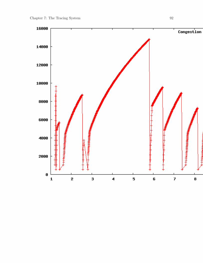
Chapter 7: The Tracing System 92
Chapter 8: Closing Remarks 93
8 Closing Remarks
8.1 Futures
This document is a work in process. We hope and expect it to grow over time to cover moreand more of the nuts and bolts of ns-3.
We hope to add the following chapters over the next few releases:• The Callback System• The Object System and Memory Management• The Routing System• Adding a New NetDevice and Channel• Adding a New Protocol• Working with Real Networks and Hosts
Writing manual and tutorial chapters is not something we all get excited about, but itis very important to the project. If you are an expert in one of these areas, please considercontributing to ns-3 by providing one of these chapters; or any other chapter you may thinkis important.
8.2 Closing
ns-3 is a large and complicated system. It is impossible to cover all of the things you willneed to know in one small tutorial.
We have really just scratched the surface of ns-3 in this tutorial, but we hope to havecovered enough to get you started doing useful networking research using our favorite sim-ulator.
– The ns-3 development team.
Index 94
Index
AApplication . . . . . . . . . . . . . . . . . . . . . . . . . . . . . . . . . . . . 15architecture . . . . . . . . . . . . . . . . . . . . . . . . . . . . . . . . . . . . 3ascii trace dequeue operation . . . . . . . . . . . . . . . . . . 40ascii trace drop operation . . . . . . . . . . . . . . . . . . . . . . 40ascii trace enqueue operation . . . . . . . . . . . . . . . . . . 40ascii trace receive operation . . . . . . . . . . . . . . . . . . . . 40ASCII tracing . . . . . . . . . . . . . . . . . . . . . . . . . . . . . . . . . 39
Bbuild . . . . . . . . . . . . . . . . . . . . . . . . . . . . . . . . . . . . . . . . . . . 3building debug version with Waf . . . . . . . . . . . . . . . 10building with build.py . . . . . . . . . . . . . . . . . . . . . . . . . . 9building with Waf . . . . . . . . . . . . . . . . . . . . . . . . . . . . . 10bus network topology . . . . . . . . . . . . . . . . . . . . . . . . . . 43
CC++ . . . . . . . . . . . . . . . . . . . . . . . . . . . . . . . . . . . . . . . . . . . . 4Channel . . . . . . . . . . . . . . . . . . . . . . . . . . . . . . . . . . . . . . . 16class Application . . . . . . . . . . . . . . . . . . . . . . . . . . . . . . 15class Node . . . . . . . . . . . . . . . . . . . . . . . . . . . . . . . . . . . . . 15command line arguments . . . . . . . . . . . . . . . . . . . . . . 33compiling with Waf . . . . . . . . . . . . . . . . . . . . . . . . . . . . 10configuring Waf . . . . . . . . . . . . . . . . . . . . . . . . . . . . . . . 10contributing . . . . . . . . . . . . . . . . . . . . . . . . . . . . . . . . . . . . 2Cygwin . . . . . . . . . . . . . . . . . . . . . . . . . . . . . . . . . . . . . . 4, 6
Ddocumentation . . . . . . . . . . . . . . . . . . . . . . . . . . . . . . . . . . 3
EEthernet . . . . . . . . . . . . . . . . . . . . . . . . . . . . . . . . . . . . . . 16
Ffirst script . . . . . . . . . . . . . . . . . . . . . . . . . . . . . . . . . . . . . 17first.cc . . . . . . . . . . . . . . . . . . . . . . . . . . . . . . . . . . . . . . . . . 17
GGNU . . . . . . . . . . . . . . . . . . . . . . . . . . . . . . . . . . . . . . . . . 4, 6
Hhelper . . . . . . . . . . . . . . . . . . . . . . . . . . . . . . . . . . . . . . . . . 17
LLinux . . . . . . . . . . . . . . . . . . . . . . . . . . . . . . . . . . . . . . . . 4, 6
logging . . . . . . . . . . . . . . . . . . . . . . . . . . . . . . . . . . . . . . . . 28Logitech . . . . . . . . . . . . . . . . . . . . . . . . . . . . . . . . . . . . . . . . 4
Mmake . . . . . . . . . . . . . . . . . . . . . . . . . . . . . . . . . . . . . . . . . . . 3Mercurial . . . . . . . . . . . . . . . . . . . . . . . . . . . . . . . . . . . . 3, 6mercurial repository . . . . . . . . . . . . . . . . . . . . . . . . . . . . 3MinGW . . . . . . . . . . . . . . . . . . . . . . . . . . . . . . . . . . . . . . . . 4myfirst.tr . . . . . . . . . . . . . . . . . . . . . . . . . . . . . . . . . . . . . . 39
Nnet device number . . . . . . . . . . . . . . . . . . . . . . . . . . . . . 40NetDevice . . . . . . . . . . . . . . . . . . . . . . . . . . . . . . . . . . . . . 16Node . . . . . . . . . . . . . . . . . . . . . . . . . . . . . . . . . . . . . . . . . . 15node number . . . . . . . . . . . . . . . . . . . . . . . . . . . . . . . . . . 40ns-3-dev repository . . . . . . . . . . . . . . . . . . . . . . . . . . . . . 3NS LOG . . . . . . . . . . . . . . . . . . . . . . . . . . . . . . . . . . . 29, 33
Pparsing ascii traces . . . . . . . . . . . . . . . . . . . . . . . . . . . . 40pcap . . . . . . . . . . . . . . . . . . . . . . . . . . . . . . . . . . . . . . . . . . 41pcap tracing . . . . . . . . . . . . . . . . . . . . . . . . . . . . . . . . . . . 41Python . . . . . . . . . . . . . . . . . . . . . . . . . . . . . . . . . . . . . . . . . 4
Rregression tests . . . . . . . . . . . . . . . . . . . . . . . . . . . . . . . . 12regression tests with Waf . . . . . . . . . . . . . . . . . . . . . . 10release repository . . . . . . . . . . . . . . . . . . . . . . . . . . . . . . . 3repository . . . . . . . . . . . . . . . . . . . . . . . . . . . . . . . . . . . . . . 6running a script with Waf . . . . . . . . . . . . . . . . . . . . . 14
Ssimulation time . . . . . . . . . . . . . . . . . . . . . . . . . . . . . . . . 40smart pointer . . . . . . . . . . . . . . . . . . . . . . . . . . . . . . . . . . 40sockets . . . . . . . . . . . . . . . . . . . . . . . . . . . . . . . . . . . . . . . . . 4software configuration management . . . . . . . . . . . . . 3system call . . . . . . . . . . . . . . . . . . . . . . . . . . . . . . . . . . . . 15
Ttarball . . . . . . . . . . . . . . . . . . . . . . . . . . . . . . . . . . . . . . . . . . 6tcpdump . . . . . . . . . . . . . . . . . . . . . . . . . . . . . . . . . . . . . . 42toolchain . . . . . . . . . . . . . . . . . . . . . . . . . . . . . . . . . . . . . 4, 6topology . . . . . . . . . . . . . . . . . . . . . . . . . . . . . . . 17, 43, 52topology helper . . . . . . . . . . . . . . . . . . . . . . . . . . . . . . . . 17trace event . . . . . . . . . . . . . . . . . . . . . . . . . . . . . . . . . . . . 40tracing . . . . . . . . . . . . . . . . . . . . . . . . . . . . . . . . . . . . . . . . 39tracing packets . . . . . . . . . . . . . . . . . . . . . . . . . . . . . . . . 39
Index 95
Uunit tests . . . . . . . . . . . . . . . . . . . . . . . . . . . . . . . . . . . . . . 12unit tests with Waf . . . . . . . . . . . . . . . . . . . . . . . . . . . . 10
WWaf . . . . . . . . . . . . . . . . . . . . . . . . . . . . . . . . . . . . . . . . . . 3, 6wireless network topology . . . . . . . . . . . . . . . . . . . . . . 52Wireshark . . . . . . . . . . . . . . . . . . . . . . . . . . . . . . . . . 41, 42www.nsnam.org . . . . . . . . . . . . . . . . . . . . . . . . . . . . . . . . . 3