nsf center for adaptive optics uco lick observatory laboratory for adaptive optics tomographic...
TRANSCRIPT

NSF Center for Adaptive OpticsUCO Lick Observatory Laboratory for Adaptive Optics
Tomographic algorithm for multiconjugate adaptive optics systems
Donald GavelCenter for Adaptive Optics
UC Santa Cruz

IPAM Workshop on Estimation and Control Problems in Adaptive Optics, Jan., 2004 2
Multi-conjugate AO Tomographyusing Tokovinin’s Fourier domain approach1
fffMfs kkk ~,~~ gsnk ,1
sg ~~~,~,~1
TN
kkk fsfgf
1Tokovinin, A., Viard, E., “Limiting precision tomographic phase estimation,” JOSA-A, 18, 4, Apr. 2001, pp873-882.
Measurements from guide stars:
Problem as posed: Find a linear combination of guide star data that best predicts the wavefront in a given science direction,

IPAM Workshop on Estimation and Control Problems in Adaptive Optics, Jan., 2004 3
Least-squares solution
A-posteriori error covariance:
00
20
022
02
2exp~
2exp~
cWW
dhhCc
cdhhihCMa
cdhhihCMc
n
kknkk
knk
fff
θθff
θθff
*~~ 1 fcIffAfg
*1 100 cIAcff
TcWW
3/11230 21069.9 fW f
IPAM Workshop on Estimation and Control Problems in Adaptive Optics, Jan., 2004 5
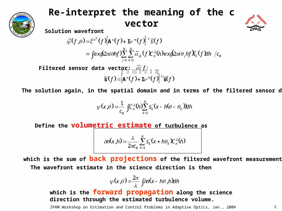
Re-interpret the meaning of the c vector
01 1
2
1
~2exp~2exp
~~,~
cdhfshfihCfhfi
fsfffcfN
j
N
kkjnjk
T
IA
Filtered sensor data vector:
f
f
fff sIAs ~
~
~ 1
The solution again, in the spatial domain and in terms of the filtered sensor data:
dhhxshCc
xN
kkkn
1
2
0
1,
Define the volumetric estimate of turbulence as
N
knkk hChxs
chxn
1
2
02,
which is the sum of back projections of the filtered wavefront measurements.
The wavefront estimate in the science direction is then
dhhhxnx ,2
,
which is the forward propagation along the science direction through the estimated turbulence volume.
Solution wavefront

IPAM Workshop on Estimation and Control Problems in Adaptive Optics, Jan., 2004 6
The new interpretation allows us to extend the approach into useful domains
• Solution is independent of science direction (other than the final forward projection, which is accomplished by light waves in the MCAO optical system)
• The following is a least-squares solution for spherical waves (guidestars at finite altitude)
• An approximate solution for finite apertures is obtained by mimicking the back propagation implied by the infinite aperture solutions
• An approximate solution for finite aperture spherical waves (cone beams from laser guide stars) is obtained by mimicking the spherical wave back propagations
ffff s sIAs ~~ 1
Dfpfsfs kFA
k ;~~~
N
knkkest hCh
hz
zs
chn
1
2
02, θxx
00
20
02 2exp~
cWW
dhhCc
cdhhz
hzihCa
n
kknskk
fff
θθff

IPAM Workshop on Estimation and Control Problems in Adaptive Optics, Jan., 2004 7
Spherical Wave Solution
Turbulence at position x at altitude happears at position
at the pupil
hz
hzx
So back-propagateposition x in pupilto position
at altitude h
hhz
zx
Frequencies f at altitude hscale down to frequencies
at the pupil
z
hzf
Frequencies f at thepupil scale up to frequencies
at altitude h
hz
zf
Forward propagation Backward propagation
Spatial domain
Frequency domain

IPAM Workshop on Estimation and Control Problems in Adaptive Optics, Jan., 2004 8
Another algorithm2 projects the volume estimates onto a finite number of
deformable mirrors
2Tokovinin, A., Le Louarn, M., Sarazin, M., “Isoplanatism in a multiconjugate adaptive optics system,” JOSA-A, 17, 10, Oct. 2000, pp1819-1827.
dhhfnhfgfd DMmm ,~,~~
mm
DMmm
mDM
m
DMDMDM
HHfJa
hHfJb
hffhf
2~2
~,
~,~
0
0
1bAg
DMnm ,,1

IPAM Workshop on Estimation and Control Problems in Adaptive Optics, Jan., 2004 9
MCAO tomography algorithm summary
Wavefront slope measurements
from each guidestar
Filter
Back-projectAlong guidestar directions
Projectonto DMs
Actuator commands
xxxs kkk ,
Convert slope to phase (Poyneer’s
algorithm)
fffs kkk ~,~~
ffff sIAs ~~ 1
dhehCc
fa
hifn
kk
kk 22
0
1
~
N
kkn
N
k
ifhn
hxshCc
hxn
efshCc
hfn k
1
2
0
1
22
0
2,
~2
,~
dhhfnhfgfd DMmm ,~,~~
mm
DMmm
mDM
m
DMDMDM
HHfJa
hHfJb
hffhf
2~2
~,
~,~
0
0
1bAg
Guide star angles k
DM conjugate heights
Field of view
mH
References:Tokovinin, A., Viard, E., “Limiting precision tomographic phase estimation,” JOSA-A, 18, 4, Apr. 2001, pp873-882.Tokovinin, A., Le Louarn, M., Sarazin, M., “Isoplanatism in a multiconjugate adaptive optics system,” JOSA-A, 17, 10, Oct. 2000, pp1819-1827.Poyneer, L., Gavel, D., and Brase, J., “Fast wave-front reconstruction in large adaptive optics systems with use of the Fourier transform,”
JOSA-A, 19, 10, October, 2002, pp2100-2111.Gavel, D., “Tomography for multiconjugate adaptive optics systems using laser guide stars,” work in progress.
k=angle of guidestar kx = position on pupil (spatial domain)f = spatial frequency (frequency domain)h = altitudeHm = altitude of DM m

IPAM Workshop on Estimation and Control Problems in Adaptive Optics, Jan., 2004 10
The MCAO reconstruction processa pictoral representation of what’s happening
Propagate light fromScience target
Measure light fromguidestars
Back-Project* to volume
Combine onto DMs
1 2 3 4
*after the all-important filtering step, which makes the back projections consistent with all the data

IPAM Workshop on Estimation and Control Problems in Adaptive Optics, Jan., 2004 11
For implementation purposes, combine steps 2 and 3 to create a reconstruction matrix
data WFSof vector
matrixfilter
1
matrixprojector
commands DMof vector
221
~~
~~
~,
,~,~~
KKKKM
DM
M
DM
kk
ifhDMn
DM
DMmm
ffvfff
fff
fsdhehfhCf
dhhfnhfgfd
k
sIAPd
sPd
bA
A simple approximation, or clarifying example: assume atmospheric layers (Cn
2) occur only at the DM conjugate altitudes.
k
kifH
mnm fseHCfd km ~~ 22
Filtered measurements from guide star kShifted during back projection
Weighted by Cn2
mm Hhhfg ,~

IPAM Workshop on Estimation and Control Problems in Adaptive Optics, Jan., 2004 12
It’s a “fast” algorithm
• The real-time part of the algorithm requires– O(N log(N))K computations to transform the guidestar measurements
– O(N) KM computations to filter and back-propagate to M DM’s
– O(N log(N))M computations to transform commands to the DM’s
– where N = number of samples on the aperture, K = number of guidestars, M = number of DMs.
• Two sets of filter matrices, A(f)+Iv(f) and PDM(f), must be pre-computed– One KxK for each of N spatial frequencies (to filter measurements)-- these
matrices depend on guide star configuration
– One MxK for each of N spatial frequencies (to compact volume to DMs)-- these matrices depend on DM conjugate altitudes and desired FOV
• Deformable mirror “commands”, dm(x) are actually the desired phase on the DM
– One needs to fit to DM response functions accordingly
– If the DM response functions can be represented as a spatial filter, simply divide by the filter in the frequency domain

IPAM Workshop on Estimation and Control Problems in Adaptive Optics, Jan., 2004 13
Simulations
• Parameters– D=30 m
– du = 20 cm
– 9 guidestars (8 in circle, one on axis)
– zLGS = 90 km
– Constellation of guidestars on 40 arcsecond radius
– r0 = 20 cm, CP Cn2 profile (7 layer)
– = 10 arcsec off axis (example science direction)
• Cases– Infinite aperture, plane wave
– Finite aperture, plane wave
– Infinite aperture, spherical wave
– Finite aperture, spherical wave (cone beam)

IPAM Workshop on Estimation and Control Problems in Adaptive Optics, Jan., 2004 14
Plane wave
129 nm rms 155 nm rms
Infinite aperture Finite aperture

IPAM Workshop on Estimation and Control Problems in Adaptive Optics, Jan., 2004 15
Spherical Wave
421 nm rms388 nm rms
155 nm rms
Infinite Aperture Finite Aperture

IPAM Workshop on Estimation and Control Problems in Adaptive Optics, Jan., 2004 16
Movie

IPAM Workshop on Estimation and Control Problems in Adaptive Optics, Jan., 2004 17
Conclusions
• MCAO Fourier domain tomography analyses can be extended to spherical waves and finite apertures, and suggest practical real-time reconstructors
• Finite aperture algorithms “mimic” their infinite aperture equivalents
• Fourier domain reconstructors are fast– Useful for fast exploration of parameter space
– Could be good pre-conditioners for iterative methods – if they aren’t sufficiently accurate on their own
• Difficulties– Sampling 30m aperture finely enough (on my PC)
– Numerical singularity of filter matrices at some spatial frequencies
– Spherical wave tomographic error appears to be high in simulations, but this may be due to the numerics of rescaling/resampling (we’re working on this)
– Not clear how to extend the infinite aperture spherical wave solution to frequency domain covariance analysis (it mixes and thus cross-correlates different frequencies)