nsg9000-40g hectoqam - harmonic inc. · nsg9000-40g hectoqam© universal edgeqam version 3.1 &...
TRANSCRIPT

NSG9000-40G HectoQAM© Universal EdgeQAM VERSION 3.1 & UP
HW and Installation User Guide
Rev H

© 2012 Harmonic Inc. All rights reserved.
Disclaimer
Harmonic reserves the right to alter the equipment specifications and descriptions in this publication without prior notice. No part of this publication shall be deemed to be part of any contract or warranty unless specifically incorporated by reference into such contract or warranty. The information contained herein is merely descriptive in nature, and does not constitute a binding offer for sale of the product described herein. Harmonic assumes no responsibility or liability arising from the use of the products described herein, except as expressly agreed to in writing by Harmonic. The use and purchase of this product do not convey a license under any patent rights, copyrights, trademark rights, or any intellectual property rights of Harmonic. Nothing hereunder constitutes a representation or warranty that using any products in the manner described herein will not infringe any patents of third parties.
Trademark Acknowledgments
Harmonic and all Harmonic product names are trademarks of Harmonic Inc. All other trademarks are the property of their respective owners.
Compliance and Approval
This equipment generates, uses, and can radiate radio frequency energy. It may cause harmful interference to radio communications if it is not installed and used in accordance with the instructions in this manual. Operation of this equipment in a residential area is likely to cause harmful interference. If this occurs, the user will be required to correct the interference at his or her own expense.
This equipment has been tested and found to comply with the limits for a Class A digital device, pursuant to Part 15, Subpart B of the Federal Communications Commission (FCC) rules.
These limits are designed to provide reasonable protection against harmful interference when the equipment is operated in a commercial environment.
This device complies with Part 15 of the FCC rules. Operation is subject to the following two conditions: (1) this device may not cause harmful interference, and (2) this device must accept any interference received, including interference that may cause undesired operation.
Connections between the Harmonic equipment and other equipment must be made in a manner that is consistent with maintaining compliance with FCC radio frequency emission limits. Modifications to this equipment not expressly approved by Harmonic may void the authority granted to the user by the FCC to operate this equipment.
WEEE/RoHS Compliance Policy
Harmonic Inc. intends to comply fully with the European Union’s Directive 2002/96/EC as amended by Directive 2003/108/EC, on Waste Electrical and Electronic Equipment, also known as “WEEE,” and Directive 2002/95/EC, as amended, on the Restriction of use of Hazardous Substances, also known as “RoHS.”
Harmonic will ensure that product which cannot be reused will be recycled in compliance with the WEEE Directive. To that end, users are advised that (1) Harmonic equipment is not to be discarded in household or office garbage, (2) Harmonic Inc. will pay the freight for shipment of equipment to be disposed of if it is returned to Harmonic, (3) customers should call the normal RMA telephone numbers to arrange for such shipment, and (4) for additional and updated information on this process customers may consult the Harmonic website: http://harmonicinc.com/pa_weee_recycle.cfm.
Harmonic will ensure that its products will be either reused or recycled in compliance with the WEEE Directive. For the latest information concerning Harmonic’s WEEE/RoHS Compliance Policy and its Recycling and Take-Back process, please visit our web site.

© 2012 Harmonic Inc. All rights reserved.
?品中的有毒有害物?或元素的名?及含量表 Names and Contents of the Toxic and Hazardous Substances or Elements in the Products if the Part is Present
?表?示哈雷公司?品中可能含有的有毒有害物?元配件的信息,除了?源于元配件供?商的物料成分?料, 亦?自其它相?的机构与?料。哈雷?品不一定使用?些元配件。This table shows those components where hazardous substances may be found in Harmonic products based on, among other things, material content information provided by third party suppliers. These components may or may not be part of the product.
除非特殊注明,哈雷公司?品的?保使用期限 均? 20 年。??保使用期限的有效条件?:必?遵循??品使用手?的?定,???品?行使用或存?。The Environmental Protective Use Period for Harmonic products is 20 years unless displayed otherwise on the product. The EPUP period is valid only when the products are operated or stored as per the conditions specified in the product manual.
O: 表示在?部件的所有均?材料中,此类有毒有害物?的含量均小于 SJ/T11363-2006 ?准所?定的限量。O: Indicates the content of the toxic and hazardous substances at the homogeneous material level of the parts is below the limit defined in SJ/T11363 2006 standard.
X: 表示至少在?部件的某一均?材料中,此类有毒有害物?的含量超出 SJ/T11363-2006 ?准?定的限量。X: Indicates that the content of the toxic and hazardous substances in at least one of the homogeneous materials of the parts is above the limit defined in SJ/T11363 2006 standard.
部件名? (Part name)
有毒有害物?或元素 (Hazardous Substance)
?(PB)
汞(Hg)
?(Cd)
六价?(CrVI)
多溴联苯(PBB)
多溴二苯醚(PBDE)
印刷?路板 (Printed Circuit Assemblies)
X O O O O O
机械?件 (Mechanical Subassemblies)
X O O O O O
光学?件 (Optical Subassemblies)
X O O O O O
电源 (Power Supplies)
X O O O O O
缆? / ?束 (Cables, harnesses)
X O O O O O
屏幕 / ?示器 (Screens, Monitors)
X O O O O O
金属零件 (Metal Parts)
O O O O O O
塑料 / 发泡材料 (Plastics, foams)
O O O O O O
电池 (Batteries)
O O O O O O

© 2012 Harmonic Inc. All rights reserved.
Standards and Agency Approval
The following tables list regulatory standards and agency approvals:
North America
Europe
Japan
Australia and New Zealand
Standards Agency Approval
EMI: FCC Part 15, Subpart B, ICES-003, Issue 2, Class A FCC
Safety: UL 60950, CSA 60950 cTUV-us Mark
Standards Agency Approval
EMI/EMC: EN55022, Class A, EN55024 CE
Safety: EN 60950 TUV-GS-Mark, CE
Standards Agency Approval
EMI: VCCI V-3 / 2000.04 VCCI
Standards Agency Approval
EMI: AS/NZS-3548: 1995 +A1: 1997 +A2: 1997 N/A

© 2012 Harmonic Inc. All rights reserved.
Documentation ConventionsThis manual uses some special symbols and fonts to call your attention to important information. The following symbols appear throughout this manual:
DANGER: The Danger symbol calls your attention to information that, if ignored, can cause physical harm to you.
CAUTION: The Caution symbol calls your attention to information that, if ignored, can adversely affect the performance of your Harmonic product, or that can make a procedure needlessly difficult.
LASER DANGER: The Laser symbol and the Danger alert call your attention to information about the lasers in this product that, if ignored, can cause physical harm to you.
NOTE: The Note symbol calls your attention to additional information that you will benefit from heeding. It may be used to call attention to an especially important piece of information you need, or it may provide additional information that applies in only some carefully delineated circumstances.
TIP: The Tip symbol calls your attention to parenthetical information that is not necessary for performing a given procedure, but which, if followed, might make the procedure or its subsequent steps easier, smoother, or more efficient.
In addition to these symbols, this manual uses the following text conventions:
Data Entry: indicates text you enter at the keyboard.
User Interface: indicates a button to click, a menu item to select, or a key or key sequence to press.
Screen Output: shows console output or other text that is displayed to you on a computer screen.
Bold: indicates the definition of a new term.
Italics: used for emphasis, cross-references, and hyperlinked cross-references in online documents.

Table of Contents
© 2012 Harmonic Inc. 6 NSG9000-40G v.3.1.0 & Up, Rev H
Table of Contents
Chapter 1 Main Features and Specifications1.1 Introduction . . . . . . . . . . . . . . . . . . . . . . . . . . . . . . . . . . . . . . . . . . . . . . . 91.2 Main Features . . . . . . . . . . . . . . . . . . . . . . . . . . . . . . . . . . . . . . . . . . . . . 91.3 NSG 9000 Physical and Power Specifications . . . . . . . . . . . . . . . . . . 11
1.3.1 Physical Dimensions . . . . . . . . . . . . . . . . . . . . . . . . . . . . . . . . . . . . . . 111.3.2 NSG 9000 Weight . . . . . . . . . . . . . . . . . . . . . . . . . . . . . . . . . . . . . . . . 111.3.3 Power Supply Specifications . . . . . . . . . . . . . . . . . . . . . . . . . . . . . . . . 121.3.4 Power Consumption from Grid . . . . . . . . . . . . . . . . . . . . . . . . . . . . . . 121.3.5 Environmental Specifications . . . . . . . . . . . . . . . . . . . . . . . . . . . . . . . 13
1.4 NSG 9000 Front Panel . . . . . . . . . . . . . . . . . . . . . . . . . . . . . . . . . . . . . 131.4.1 Front Bezel . . . . . . . . . . . . . . . . . . . . . . . . . . . . . . . . . . . . . . . . . . . . . . 131.4.2 EIA-232 Serial Port . . . . . . . . . . . . . . . . . . . . . . . . . . . . . . . . . . . . . . . 131.4.3 Front Panel LEDs . . . . . . . . . . . . . . . . . . . . . . . . . . . . . . . . . . . . . . . . . 141.4.4 Control Panel . . . . . . . . . . . . . . . . . . . . . . . . . . . . . . . . . . . . . . . . . . . . 141.4.5 Air Inlets . . . . . . . . . . . . . . . . . . . . . . . . . . . . . . . . . . . . . . . . . . . . . . . . 141.4.6 Cooling Fans . . . . . . . . . . . . . . . . . . . . . . . . . . . . . . . . . . . . . . . . . . . . . 14
1.5 Back Panel . . . . . . . . . . . . . . . . . . . . . . . . . . . . . . . . . . . . . . . . . . . . . . . 151.5.1 Processing Module . . . . . . . . . . . . . . . . . . . . . . . . . . . . . . . . . . . . . . . 151.5.2 QAM-RF Modules . . . . . . . . . . . . . . . . . . . . . . . . . . . . . . . . . . . . . . . . . 191.5.3 Power Supply . . . . . . . . . . . . . . . . . . . . . . . . . . . . . . . . . . . . . . . . . . . . 201.5.4 What’s Next... . . . . . . . . . . . . . . . . . . . . . . . . . . . . . . . . . . . . . . . . . . . . 21
Chapter 2 Installation2.1 Unpacking the NSG 9000 Platform . . . . . . . . . . . . . . . . . . . . . . . . . . 222.2 Installation Guidelines. . . . . . . . . . . . . . . . . . . . . . . . . . . . . . . . . . . . . . 22
2.2.1 Rack Specifications . . . . . . . . . . . . . . . . . . . . . . . . . . . . . . . . . . . . . . . 222.2.2 Rack Ventilation . . . . . . . . . . . . . . . . . . . . . . . . . . . . . . . . . . . . . . . . . . 222.2.3 Rack Positioning and Device Mounting . . . . . . . . . . . . . . . . . . . . . . . 232.2.4 Rack Weight . . . . . . . . . . . . . . . . . . . . . . . . . . . . . . . . . . . . . . . . . . . . . 232.2.5 Power Source and Wiring Specifications . . . . . . . . . . . . . . . . . . . . . . 242.2.6 Facility Cooling Requirements . . . . . . . . . . . . . . . . . . . . . . . . . . . . . . 25
2.3 Installing NSG 9000-40G Devices . . . . . . . . . . . . . . . . . . . . . . . . . . . 252.3.1 Required Tools for Installation . . . . . . . . . . . . . . . . . . . . . . . . . . . . . . 25
2.4 Inserting Processing/QAM-RF Modules . . . . . . . . . . . . . . . . . . . . . . . 262.4.1 Guidelines for Handling Processing/QAM-RF Modules . . . . . . . . . . 26
Chapter 3 Cabling3.1 Device Dimensions . . . . . . . . . . . . . . . . . . . . . . . . . . . . . . . . . . . . . . . . 31
3.1.1 Back Panel Measurements . . . . . . . . . . . . . . . . . . . . . . . . . . . . . . . . . 313.2 Cabling the GbE Ports. . . . . . . . . . . . . . . . . . . . . . . . . . . . . . . . . . . . . . 32
3.2.1 Mirroring a GbE Input Port . . . . . . . . . . . . . . . . . . . . . . . . . . . . . . . . . 323.3 Connecting the QAM-RF Output Cables. . . . . . . . . . . . . . . . . . . . . . . 323.4 Connecting the Ethernet Cables . . . . . . . . . . . . . . . . . . . . . . . . . . . . . 33
Table of Contents
© 2012 Harmonic Inc. 7 NSG9000-40G v.3.1.0 & Up, Rev H
3.5 Cabling the DTI Ports . . . . . . . . . . . . . . . . . . . . . . . . . . . . . . . . . . . . . . 333.6 Connecting the ASI Monitoring Port Cables. . . . . . . . . . . . . . . . . . . . 333.7 Connecting Power. . . . . . . . . . . . . . . . . . . . . . . . . . . . . . . . . . . . . . . . . 33
3.7.1 Grounding the Mounted Devices . . . . . . . . . . . . . . . . . . . . . . . . . . . . 333.7.2 Connecting to the Power Outlet . . . . . . . . . . . . . . . . . . . . . . . . . . . . . 34
3.8 Boot-Up Sequence . . . . . . . . . . . . . . . . . . . . . . . . . . . . . . . . . . . . . . . . 343.9 Establishing Ethernet Connection . . . . . . . . . . . . . . . . . . . . . . . . . . . . 35
3.9.1 What’s Next... . . . . . . . . . . . . . . . . . . . . . . . . . . . . . . . . . . . . . . . . . . . . 35
Chapter 4 Maintenance4.1 Cooling Fans Unit . . . . . . . . . . . . . . . . . . . . . . . . . . . . . . . . . . . . . . . . . 36
4.1.1 Removing and Replacing the Cooling Fans Unit . . . . . . . . . . . . . . . . 364.2 Hot Swapping Power Supply Unit . . . . . . . . . . . . . . . . . . . . . . . . . . . . 38
Appendix A Wiring the –48 VDC Power Supply

List of Figures
© 2012 Harmonic Inc. 8 NSG9000-40G, v.3.1.0 & Up, Rev H
List of Figures
Figure 1–1: NSG9000-40G Front panel . . . . . . . . . . . . . . . . . . . . . . . . . . . . . . . . . . . . . . . . . . . . 13Figure 1–2: NSG9000-40G Back Panel (picture to be updated) . . . . . . . . . . . . . . . . . . . . . . . . 15Figure 1–3: NSG9000-40G Processing Module (picture to be updated). . . . . . . . . . . . . . . . . . 15Figure 1–4: SFP Modules. . . . . . . . . . . . . . . . . . . . . . . . . . . . . . . . . . . . . . . . . . . . . . . . . . . . . . . . 18Figure 1–5: NSG9000-40G QAM-RF Module . . . . . . . . . . . . . . . . . . . . . . . . . . . . . . . . . . . . . . . 19Figure 2–1: Inserting a QAM-RF Module (to be updated) . . . . . . . . . . . . . . . . . . . . . . . . . . . . . 27Figure 2–2: Secure QAM-RF Module (picture to be updated) . . . . . . . . . . . . . . . . . . . . . . . . . . 27Figure 2–3: QAM-RF Terminator . . . . . . . . . . . . . . . . . . . . . . . . . . . . . . . . . . . . . . . . . . . . . . . . . 28Figure 2–4: Unscrewing the QAM-RF Module (picture to be updated) . . . . . . . . . . . . . . . . . . 28Figure 2–5: Module Knob Holders (picture to be updated) . . . . . . . . . . . . . . . . . . . . . . . . . . . . 28Figure 2–6: Processing Module . . . . . . . . . . . . . . . . . . . . . . . . . . . . . . . . . . . . . . . . . . . . . . . . . . 29Figure 2–7: Replacing Processing Module (picture to be updated) . . . . . . . . . . . . . . . . . . . . . . 29Figure 3–1: NSG9000-40G Dimensions . . . . . . . . . . . . . . . . . . . . . . . . . . . . . . . . . . . . . . . . . . . . 31Figure 3–2: NSG9000-40G Back Panel Measurements . . . . . . . . . . . . . . . . . . . . . . . . . . . . . . . 31Figure 4–1: Fan Unit . . . . . . . . . . . . . . . . . . . . . . . . . . . . . . . . . . . . . . . . . . . . . . . . . . . . . . . . . . . 36Figure 4–2: Detaching Front Panel. . . . . . . . . . . . . . . . . . . . . . . . . . . . . . . . . . . . . . . . . . . . . . . . 37Figure 4–3: NSG9000-40G Power Supply Units . . . . . . . . . . . . . . . . . . . . . . . . . . . . . . . . . . . . . 38Figure 4–4: Pulling Out Power Supply . . . . . . . . . . . . . . . . . . . . . . . . . . . . . . . . . . . . . . . . . . . . . 38Figure A–1: DC Connector. . . . . . . . . . . . . . . . . . . . . . . . . . . . . . . . . . . . . . . . . . . . . . . . . . . . . . . 41Figure A–2: Assembling the DC Input Power Cable . . . . . . . . . . . . . . . . . . . . . . . . . . . . . . . . . . 42

© 2012 Harmonic Inc. 9 NSG9000-40G v.3.1.0 & Up, Rev H
Chapter 1Main Features and Specifications
1.1 IntroductionNSGTM (Network Services Gateway) 9000-40G is Harmonic’s advanced modular 2-RU platform. The NSG 9000-40G platform is a high density edgeQAM system, capable of scaling up to 648 QAM-RF output transport streams. The number of the delivered transport streams is set according to the device configuration and number of QAM-RF modules mounted in the slots of the device.
This guide describes the NSG 9000-40G specifications, and instructs you on how to install
and cable the NSG 9000-40G.
1.2 Main FeaturesThe following table describes the main features of the NSG 9000-40G platform:
Table 1–1: NSG 9000-40G Main Features
Component Feature Description
Chassis Chassis 2-RU, mounts in Electronic Industries Association (EIA) standard rack
Hot-swappable Front Panel The front panel module includes four cooling fans, LCD display panel and a keypad, and indication LEDs. The module may be removed for maintenance purposes while the system is operational.
Indication LEDs 2 power, alarm and 9 output status LEDs.
Processing module
4 x 1Gbe port 4 x 10GbE port (port operation is firmware dependent)
Provides eight independent ports receiving simultaneously different feeds
Input rate is SFP dependent: SFP - 1G SFP - up to 1000Mbps per port
SFP+ - 10G SFP - up to 10,000Mbps per port
1 x ASI monitoring port Any GbE port
The unit duplicates any requested QAM channel to the ASI output port/GbE port for monitoring purposes.
Back panel LEDs Activity and alarm LED pair for each GbE port(12 LEDs in all).
2x10Base-T/100Base-T Ethernet ports
Two independent Ethernet ports, typically Eth1 is used for management and Eth2 for CAS.
2xDTI ports Two DTI ports, typically used for M-CMTS applications.
USB Port Located on the back panel.

Chapter 1 Main Features and Specifications Main Features
© 2012 Harmonic Inc. 10 NSG9000-40G v3.1.0 & Up Rev H
QAM-RF modules
Up to nine QAM-RF modules,Hot-swappable
Up to 9 QAM-RF modules may be mounted in the chassis. Modules may be added or removed while the system is operational.
2xRF ports per QAM-RF module, overall up to 72xQAM RF ports
RF bandwidth per port - 384MHz Number of QAMs per port:
Annex B and C - up to 36xQAM channels
Annex A - up to 26xQAM channels
Up to 648 QAM-RF channels
Each port carries up to 36 QAM channels combined and upconverted. For further information, refer to page 19. QAM Mode:
ITU-T J.83 Annex-A (DVB): 8 MHz
ITU-T J.83 Annex-B: 6 MHz
ITU-T J.83 Annex-C (Japan): 6 MHz
QAM Constellations: ITU-T J.83 Annex-A:16, 32, 64, 128, 256
ITU-T J.83 Annex-B: 64, 256
ITU-T J.83 Annex-C:16, 32, 64, 128, 256
For further QAM-RF specifications, see product specification sheet.
QAM-RF module
Maximum output bit rate ITU-T J.83 Annex-A Up to 26xQAM channels per physical port (Triple
QAM)
Up to 52xQAM channels per module
Max output bitrate per QAM channel - 51.287 Mbps
ITU-T J.83 Annex-B: Up to 36xQAM channels per physical port (Quad
QAM)
Up to 72xQAM channels per module
Max output bitrate per QAM channel - 38.811 Mbps
ITU-T J.83 Annex-C: Up to 36xQAM channels per physical port (Quad
QAM)
Up to 72xQAM channels per module
Max output bitrate per QAM channel - 39.171 Mbps
Table 1–1: NSG 9000-40G Main Features
Component Feature Description

Chapter 1 Main Features and Specifications NSG 9000 Physical and Power Specifications
© 2012 Harmonic Inc. 11 NSG9000-40G v3.1.0 & Up Rev H
1.3 NSG 9000 Physical and Power Specifications
1.3.1 Physical Dimensions
1.3.2 NSG 9000 WeightThe table lists worse case values of weight for several model combinations:
Power Supply AC/DC Power Supply Options
Two distinct types of Power Supply are available: AC DC
Hot Swappable redundant power supply
Two independent Power Supply units may be mounted in the chassis. The units can be removed or inserted while the system is operational.
Current and load sharing When operating with two Power Supplies, load is shared and balanced between the two modules.
Table 1–2: Physical Dimensions
Dimension Inches mm
Height 3.47 88.1
Width 19.00 482.6
Total Length (front to back) 22.88 581.2
Depth (From rack mount fixture to back of device)
21.78 553.4
Table 1–3: NSG 9000 Weight
Configuration Weight (lb.) Weight (kg)
Chassis with front panel and main processing board
26.8 12.2
Power Supply AC/DC 3.9 1.8
QAM-RF blade 2.50 1.13
Full platform(chassis + 2xPS + 9xQRF)
63 28.6
Full platform(chassis + 1xPS + 9xQRF)
59 26.8
Table 1–1: NSG 9000-40G Main Features
Component Feature Description

Chapter 1 Main Features and Specifications NSG 9000 Physical and Power Specifications
© 2012 Harmonic Inc. 12 NSG9000-40G v3.1.0 & Up Rev H
1.3.3 Power Supply Specifications Harmonic sells power supply units that have been thoroughly qualified to operate with the NSG 9000-40G device. Table 1–4 lists power specifications of a fully populated unit together with the Harmonic part numbers for the qualified power supply modules. Use these part numbers for ordering your power supply modules.
CAUTION: Both power supply units should be of the same part number. Power supply units with different part numbers, may adversely affect the performance of the QAM-RF output signal.
CAUTION: Power Supply units with the following part numbers are not qualified for NSG9000-40G: NSG-PS-AC-01, NSG-PS-DC-01, NSG-PS-AC-02 and NSG-PS-DC-02.
1.3.4 Power Consumption from GridThe following table lists the power consumption from grid. The consumption of the NSG9000-40G unit depends on the ambient temperature in which it operates, as reflected in the table. Use the consumption figure of a single module in order to calculate the consumption of a partly-populated chassis:
For installation details, see 2.2.5.2 Overcurrent protection on page 24.
For cabling details, see 3.7 Connecting Power on page 33.
Table 1–4: Power Supply Units Specifications
Harmonic Part Number
PS Type
Input Voltage Range Input Line Frequency
NSG-PS-AC-03 AC 100 to240 VAC 47 to 63 Hz
NSG-PS-DC-03 DC -40 to -60 VDC N/A
NSG-PS-DC-04 DC -42 to -60 VDC N/A
Table 1–5: Power Consumption from Grid
Ambient TemperaturePower Consumption from Grid (Watts)
Fully Populated Chassis Single QAM-RF Module
Typical consumption at 25°c 765 64
Max consumption at 50°c 810 70

Chapter 1 Main Features and Specifications NSG 9000 Front Panel
© 2012 Harmonic Inc. 13 NSG9000-40G v3.1.0 & Up Rev H
1.3.5 Environmental SpecificationsThe following table lists the environmental specifications for the NSG 9000 (NSG-9K-CS-11):
1.4 NSG 9000 Front PanelThe front panel of the NSG 9000 platform contains the following:
Front bezel
RS-232 connector
LEDs
Control panel
Four cooling fans
The following figure illustrates the front panel of the NSG 9000 platform:
Figure 1–1: NSG9000-40G Front panel
1.4.1 Front BezelThe NSG 9000 platform has a detachable front bezel that snaps on top of the control panel. The air inlets located on the bezel provide air flow. See 1.4.5 Air Inlets on page 14.
1.4.2 EIA-232 Serial PortThe EIA-232 serial port may be used to configure the Ethernet port IP addresses. You can use the serial port for monitoring and manual maintenance operations. The EIA-232 serial port has a female DB-9 D-type connector.
Table 1–6: Environmental Specifications
Parameter Description
Operating temperature 0 to 50 °C (32 to 122 °F)
Storage temperature –20 to 80 °C (–4 to 176 °F)
Relative humidity Maximum 95% non-condensing
Ventilation When fans operate at full speed, air flow through the device is at least 2.745m³/min (97CFM) per NSG 9000-40G unit.
Serial port Front panel LEDs Control panel with keys Air inlets

Chapter 1 Main Features and Specifications NSG 9000 Front Panel
© 2012 Harmonic Inc. 14 NSG9000-40G v3.1.0 & Up Rev H
1.4.3 Front Panel LEDsThe front panel of the NSG 9000 platform includes the following LEDs:
Output Modules LEDs - nine LEDs for monitoring the status of the modules.
Operation Status LEDs - include two Power supply LEDs and an Alarm LED. The Operation Status LEDs enable to monitor the status of the NSG 9000 power and of the unit’s operation. The following table describes the front panel LEDs, from left to right and from top down.
1.4.4 Control PanelThe control panel consists of an LCD display area and a keypad. The control panel enables preliminary configuration and basic monitoring of the device. It is usually used for standalone devices. For further information, see NSG 9000-40G Software User Guide.
1.4.5 Air InletsAir inlets are located along the lower, upper right and middle of the front panel. The air inlets are designed to provide maximum air flow. The air flow is critical for maintaining the proper temperature range. Fans in the front unit draw air in through the front inlets.
CAUTION: Do not obstruct the airflow when mounting the device on the rack. Severe equipment damage can result when the device cannot properly exhaust the airflow.
1.4.6 Cooling FansThe NSG 9000 platform uses four fans to control the temperature during operation. The fans located in the front of the device, use air from the front and exhaust it to the rear of the device. Each fan has a speed control and the CPU manages their speed to increase Mean time Between Failures and to lower the noise level.
All four fans are mounted on the back side of the front panel to allow a quick and easy hot swap in case of a fan failure. See 4.1.1 Removing and Replacing the Cooling Fans Unit on page 36.
Table 1–7: Front Panel LEDs
LED Color Description
Power PS1 & PS2 Green/Red ON (Green) - Power supply unit is working properly.ON (Red) - Power supply unit is faulty.OFF - Power supply unit is not mounted in the slot.
Alarm Red/Orange ON (Red) - Indicates an alarm has been activated in the device. Refer to NSG 9000 Software User’s Guide for further details.OFF - Indicates no alarm activated.
Module 1 - 9 Green/Red/Orange ON (Green) - A module is mounted and it is working properly.ON (Red) - A module is mounted and is faulty.OFF - No module is mounted.

Chapter 1 Main Features and Specifications Back Panel
© 2012 Harmonic Inc. 15 NSG9000-40G v3.1.0 & Up Rev H
1.5 Back PanelThis section describes the back panel of the NSG 9000 platform. The back panel of the NSG 9000 platform includes the following:
Processing module
9 x Module Slots
2 x Power supply
Grounding terminal
Figure 1–2: NSG9000-40G Back Panel (picture to be updated)
1.5.1 Processing Module The Processing module is the main module of the NSG 9000 platform. It includes the communication interfaces of the unit and the GbE interfaces. The Processing module manages, configures and monitors the device and its modules. It is a swappable module that is easily mounted from the rear side of the platform. The Central Processing module includes the following components:
Figure 1–3: NSG9000-40G Processing Module (picture to be updated)
2 x Ethernet ports
1 x CAS Ethernet port
2 x DTI ports for M-CMTS application
1 x USB port
1 x ASI Monitor port
4 x 1GbE port
4 x 10GbE port
NOTE: In case of processing module malfunction, replace the module as instructed in 2.4 Inserting Processing/QAM-RF Modules on page 26 and send the faulty module to Harmonic.
Processing module 9 x populated Module slots
2 x Power supply
Grounding terminal
2 x Ethernet ports
2 x DTI ports (optional)
ASI monitor port 4 x 1GbE ports 4 x 10GbE ports

Chapter 1 Main Features and Specifications Back Panel
© 2012 Harmonic Inc. 16 NSG9000-40G v3.1.0 & Up Rev H
1.5.1.1 Ethernet Ports
The Ethernet ports allow connection to separate networks. The Ethernet ports are labeled ETH1 and ETH2. ETH1 is a management port and ETH2 is usually used for CAS. The following table lists the specifications of the Ethernet ports.
For cabling instructions, see 3.4 Connecting the Ethernet Cables on page 33.
1.5.1.2 USB Port
The USB port, labeled USB.
1.5.1.3 DTI Ports
The DTI ports, labeled DTI1 and DTI2, allow the NSG 9000 to operate in an M-CMTS application. The following table lists the DTI ports specifications:
1.5.1.4 ASI Monitoring Port
The NSG 9000 platform may duplicate one of the output transport streams to the ASI output port designed for monitoring purposes. Use this port to connect to devices that accept ASI input such as an MPEG analyzer. The following table lists the specifications of the ASI monitoring port.
For cabling instructions, see 3.6 Connecting the ASI Monitoring Port Cables on page 33.
1.5.1.5 GbE Input Ports
The NSG 9000 platform includes eight GbE ports labeled as follows:
GbE1-4 - for 1Gbps. These ports support fiber or copper cables and use SFP transreceivers.
10GbE5-8 - for 10Gbps. These ports support fiber cables only and use SFP+ transreceivers.
Table 1–8: Ethernet Ports Specifications
Parameter Specification
Ethernet 10/100 Base-T ports
Connector RJ-45 (1 Management, 1 CAS)
Table 1–9: DTI Ports Specifications
Parameter Specification
Input signal Complies with DOCSIS 3.0 DTI
Table 1–10: ASI Monitoring Specifications
Parameter Specifications
MPEG Format ASI Output
Connector Type BNC, 75
Configuration Configurable mirroring per QAM
MPEG Format 188 Bytes per TS packet

Chapter 1 Main Features and Specifications Back Panel
© 2012 Harmonic Inc. 17 NSG9000-40G v3.1.0 & Up Rev H
The following table lists the GbE port specification:
The NSG 9000 back panel features two LEDs for each GbE port. The following table describes the LEDs:
1.5.1.6 SFP Module
The SFP (Small Form Factor Pluggable) module converts optical data into electrical data and vice versa. The SFP modules allow the NSG to receive input signals over a variety of physical interfaces:
SFP
Single-mode optical interface (1000 Base-LX)
Multi-mode optical interface (1000 Base-SX)
Copper interface (1000 Base-T)
SFP +
Multi-mode optical interface (1000 Base-SX 1G Ethernet, 10GBase-SR/SW 10G Ethernet)
The following figure illustrates an SFP module:
Table 1–11: GbE Port Specifications
Parameter Specification
Connector SFP+ transreceiver for fiber cable only SFP transreceiver for either fiber of copper cables
Maximum input bitrate SFP Line rate up to 1000 Mbps
Processing up to 960Mbps
SFP+ Line rate up to 10,000Mbps
Processing up to 9600Mbps
Maintenance Swappable
Table 1–12: LEDs of GbE Ports
LED Color Description
Activity GreenBlinking green
Illuminates when a live fiber is connected and a network link is detected.
Blinking when real traffic flows through the link.
Error Yellow Illuminates when an alarm is issued Off when port is inactive or no alarm has been
issued.

Chapter 1 Main Features and Specifications Back Panel
© 2012 Harmonic Inc. 18 NSG9000-40G v3.1.0 & Up Rev H
Figure 1–4: SFP Modules
Warning: Class I laser product. (IEC/EN 60825-1; 21CFR SubChapter J (1040.10 and 1040.11)
You can use either of the following types of SFP depending on the cable/fiber type you are using.
Harmonic sells SFP modules that have been thoroughly qualified to operate with the NSG 9000 device. These SFPs are made by Finisar, and may be purchased either directly from Harmonic, or from other sources.
Table 1–13 lists the Harmonic part numbers for the qualified SFP modules, as well as the matching Finisar part numbers for the same modules. Use these part numbers for ordering your SFP modules.
NOTE: To be eligible for support by Harmonic, use qualified SFPs only.
An optical SFP has two LC sockets, Receive(Rx) and Transmit(Tx). Use Multimode or Singlemode fiber optics to connect your Gigabit Ethernet switch to the Rx socket. If bi-directional topology is used, connect the Tx socket back to the switch.
Table 1–13: 1Giga SFP Modules
Harmonic Part Num. Fiber/Cable Type Connector
TypeWave Length
Max. Cable/Fiber Length
Qualified Finisar SFP Model Part Num.
GSF9311-02 Multimode fiber 2 x LC 850 nm 550m FTLF8519P2BNL
GSF9322-02 Singlemode fiber 2 x LC 1310 nm 10 km FTLF1319P1BTL
GSF9132-02 Singlemode fiber 2 x LC 1550 nm 70 km FTLF1621P1BCL
GSF9100-02 Shielded and grounded CAT-6 or CAT-7
1 x RJ-45 N/A 100m FCLF-8521-3
Table 1–14: 10Giga SFP+ Modules
Harmonic Part Num. Fiber/Cable Type Connector
TypeWave Length
Max. Cable/Fiber Length
Qualified Finisar SFP Model Part Num.
GSF9400-02 Multimode fiber 2 x LC 850nm 300m FTLX8571D3BCV
SFP copper
SFP fiber
1Giga SFP 10Giga SFP+

Chapter 1 Main Features and Specifications Back Panel
© 2012 Harmonic Inc. 19 NSG9000-40G v3.1.0 & Up Rev H
1.5.2 QAM-RF Modules
1.5.2.1 Module Slots
The back panel of the NSG 9000 platform includes nine module slots labeled Module 1 to nine. Each one of the slots accommodates a single QAM-RF module. The following figure illustrates the arrangement of the slots at the back panel of the device:
1.5.2.2 QAM-RF Modules
Figure 1–5: NSG9000-40G QAM-RF Module
Edge-connector
Module screws
Module knob-handles
RF ports with termination
Module screws
RF ports with termination

Chapter 1 Main Features and Specifications Back Panel
© 2012 Harmonic Inc. 20 NSG9000-40G v3.1.0 & Up Rev H
NSG 9000 supports QAM-RF module NSG-36R1G. Each QAM-RF module performs QAM modulation and up conversion of the QAM signal. Each QAM-RF module includes two QAM-RF ports labeled 1 and 2. Each port may output up to eight channels as your license permits. For further details refer to the NSG 9000-40G Online Help or to the NSG 9000-40G SW User’s Guide. The following table provides the RF port specifications:
NOTE: For detailed specifications, see NSG 9000-40G data sheet.
Each module may be configured offline and when mounted into the slot, the system identifies the inserted module. The modules are hot swappable and are mounted and plugged from the rear side of the device.
For information on how to connect the ports, see 3.3 Connecting the QAM-RF Output Cables on page 32.
1.5.3 Power SupplyThe NSG 9000 device is furnished with two hot swappable redundant AC or DC power supply units. Each power supply unit easily accommodates the power consumption of a fully populated device. When both power supply units are plugged in and connected to the mains, the power supply units operate in current sharing mode. For power consumption specifications, see 1.3.3 Power Supply Specifications on page 12.
The physical dimensions of the AC/DC power supply unit: 40mmH x 90mmW x 440mmD.
Each power supply unit features two LEDs. The following table describes the LEDs:
For instructions to connect the AC power supply, see 3.7 Connecting Power on page 33.
Table 1–15: RF Port specifications
Parameter Description
Connector Male F connector
Cable RG6 (75Ohm, 0-3GHz)RG59 (75Ohm, 0-3GHz)The female RF connectors are designed to accept cables with center pin diameter of 0.68-1.73mm (0.026"- 0.068"). Cables that do not meet this requirement must be mounted with crimp-on connector of the required dimensions.
Output center frequency per QAM-RF
ANNEX A 54 - 998MHz ANNEX B and C 53 - 999MHzNOTE: Currently only ANNEX B is supported
Table 1–16: Power Supply LEDs
LED Color Description
In Ok Green Illuminates when mains input voltage is present.
Out Ok Green Illuminates when output voltage is greater than 80% of the nominal output rate.

Chapter 1 Main Features and Specifications Back Panel
© 2012 Harmonic Inc. 21 NSG9000-40G v3.1.0 & Up Rev H
The -48 VDC power supply unit is supplied with the required 3-pin male connector. See Wiring the –48 VDC Power Supply on page 40 for instructions to connect the power supply.
NOTE: Consideration should be given to the connection of the equipment to the supply circuit and the effect that overloading of circuits might have on overcurrent protection and supply wiring. Appropriate consideration of equipment nameplate ratings should be used when addressing this concern.
1.5.4 What’s Next...The next step is to unpack and cable the NSG 9000-40G platform, as described in the following chapter.

© 2012 Harmonic Inc. 22 NSG9000-40G v.3.1.0 & Up, Rev H
Chapter 2Installation
This chapter instructs you on how to install the NSG 9000 device. For best results, perform the required actions according to following order:
Unpack the NSG 9000 devices
Read the installation guidelines
Install the NSG 9000 devices
Insert the QAM-RF modules
2.1 Unpacking the NSG 9000 PlatformThe NSG 9000 platform comes in a specially designed shipping container that ensures its safety during shipping and handling. To avoid damaging the NSG 9000 platform, unpack it carefully. The container includes the following:
Chassis - front panel is attached but no modules are mounted
Processing module - the module is static sensitive. Unpack, following the ESD guidelines on page 26.
The QAM-RF modules and power supply units are shipped separately.
2.2 Installation GuidelinesNOTE: The NSG 9000 platforms are used in restricted access locations.
NOTE: To prevent body injury when mounting or servicing this platform in a rack, you must take special precautions to ensure that the system remains stable. Read the following guidelines to assure your safety.
2.2.1 Rack Specifications Install the 2-RU chassis in the following rack:
A standard EIA 19-inch computer rack with at least 30” (76cm) deep and 40RU high. In addition, recommended rack: 36” (91cm) or 40” (102cm) depth.
To allow free air flow, the rack must be completely open at its front side. See Table 2–1: Guidelines and Specifications for Mounting a Device on page 23.
The rack should be mounted with side walls and a back door.
The back door should have ventilation slots either at its bottom part only or throughout the height of the door.
2.2.2 Rack VentilationA typical rack, a rack with an open front and top and with ventilation slots at the back, should enable free flow of hot air into the air conditioning system intake. The rack should meet the following:
Typical NSG air flow is front to back.
NSG air flow as indicated in 1.3.5 Environmental Specifications on page 13

Chapter 2 Installation Installation Guidelines
© 2012 Harmonic Inc. 23 NSG9000-40G v.3.1.0 & Up, Rev H
2.2.3 Rack Positioning and Device Mounting
2.2.3.1 Rack positioning
From front - leave clearance of at least 25”(63cm) from the front to any neighboring cabinet/wall.
From back - leave clearance of at least 20”(51cm) from the back to any neighboring cabinet/wall.
Ensure that the front of the rack is not directly exposed to the air-outlet side of any other racks.
2.2.3.2 Device Mounting
The following table lists the guidelines and specifications for mounting the NSG 9000 devices on a rack:
NOTE: Do not obstruct the airflow of the platform. Severe equipment damage can result when the device cannot properly exhaust the airflow.
2.2.4 Rack Weight1. Check the allowed floor load of the facility.
2. Calculate the total weight and load according to the following parameters:
Table 2–1: Guidelines and Specifications for Mounting a Device
Parameter Description
Occupied Space 2 rack unit
Mounting Order Partially filled rack - load rack from the bottom to the top with the heaviest component at the bottom of the rack.
Max Number According to allowed floor load. See, 2.2.4 Rack Weight on page 23.Spacing between units (1RU or more) is recommended for ease of cabling. Block the spaces between units as explained in this table in Open space.
Mounting Method Mount each device on supporting rails provided by Harmonic in a separate kit (P/N RM-4-30). Install the rack-mounting rails before mounting the device on the rack.
Open space To prevent hot air circulation, all open spaces below and above the devices should be closed with a blank panel.
Cabling Route all cables at the back panel along the sides of the rack to allow pulling out the power supply unit and QAM-RF modules.
Table 2–2: Total Load and Weight
Item Value (US) Value (metric)
Single fully loaded NSG 9000 unit 63lbs 28.6Kg
Footprint of a typical 23"x30" rack 4.8sqr. Ft 0.45m2

Chapter 2 Installation Installation Guidelines
© 2012 Harmonic Inc. 24 NSG9000-40G v.3.1.0 & Up, Rev H
For partial NSG 9000 configuration, see 1.3.2 NSG 9000 Weight on page 11.
3. Limit the number of NSG 9000 devices on a rack according to the allowed floor load. Take into account also additional equipment to be mounted on the rack.
2.2.5 Power Source and Wiring Specifications
2.2.5.1 Redundant power supply
When installing NSG 9000 devices with a redundant power supply, both power supply units should be fed by different power sources:
Dual AC supplies - use two different phases of the AC power plant.
Dual DC supplies - use two distinct DC sources (A line and B line). It is highly recommended to maintain regularity, and connect all top power supply units to the A line and all bottom power supply units to the B line.
NOTE: To ensure optimal RF output performance, verify that both power supply units are identical - they both have the same part number.
2.2.5.2 Overcurrent protection
NOTE: Overcurrent protection devices must meet applicable national and local electrical safety codes and be approved for the intended application.
To ensure adequate over-current protection, mount power feed lines with circuit breakers (CB) of the appropriate rating. Power feed to the NSG9000 should be segmented as specified below:
When using DC power supply, overcurrent protection should be provided by a fuse panel, with a separate fuse for each individual NSG9000 unit. This fuse is meant primarily for protecting the DC power source from damage in case of an internal power supply problem. The following table lists recommended fuse types for the external fuse panel:
Table 2–3: Overcurrent Protection
Nominal Input
Voltage
Max Power consumption
(Watts)
Max Steady State Current
(Amp)
In Rush Current Draw
(Amp)Number of Units per CB
110VAC 810 9.9 30 15A CB - 1 unit20A CB - 1 unit
220VAC 810 4.6 35 15A CB - up to 2 unit20A CB - up to 3 units
-48VDC 810 21.0 25 N/A
Table 2–4: Recommended Fuse Types
Power Supply Recommended Fuse
NSG-PS-DC-03 25 Amp GMT, 60 VDC/125 VAC rating, Fast-acting 25 Amp, 250 VAC rating, Slow-blow.
NSG-PS-DC-04 20Amp, 250 VAC, Slow-blow

Chapter 2 Installation Installing NSG 9000-40G Devices
© 2012 Harmonic Inc. 25 NSG9000-40G v.3.1.0 & Up, Rev H
For additional details on AC/DC power source requirements, see Wiring the –48 VDC Power Supply on page 40.
2.2.5.3 Grounding
Every rack must be properly earthed, connected to the ground bus of the plant.
Each NSG 9000 device in the rack must also be connected to the main Earth line of the rack, using a 12 AWG copper wire. See 3.7.1 Grounding the Mounted Devices on page 33.
2.2.6 Facility Cooling Requirements The NSG 9000 power consumption and therefore generated heat varies depending on the ambient temperature. The table below specifies the cooling requirements for worst-case conditions (50°c) and typical conditions (25°c).
The required cooling capacity of the facility's air conditioning system assumes 15% general leakage of a typical air conditioning system and 25% latent heat.
NOTE: It is assumed that the head-end air conditioning system is designed to circulate the air in a manner that ensures the same ambient temperature for all the NSG 9000 devices in a rack.
Ambient temperature for a continuously operating device should be 25°c. NSG 9000 can continuously operate in ambient temperature of up to 50°c. However, continuous operation in a high ambient temperature shortens the device lifetime.
2.3 Installing NSG 9000-40G Devices
2.3.1 Required Tools for Installation Four screws to secure the unit to the rack
A screwdriver for fastening the screws
Supporting rails provided by Harmonic in a separate kit(P/N RM-4-30).
To install the NSG 9000 platform in a rack:
NOTE: It is recommended to install the NSG 9000 platform before mounting any cards or modules.
1. Install the rack-mounting rails before mounting the device on the rack.
2. Place the 2-RU chassis on the rack and slide it along the supporting rails.
3. Push the device back until the rack-mount holes in the front of the device line up with the rack posts.
4. Insert four screws through the mount holes in the front of the device to go through the corresponding holes on the rack posts.
5. Tighten the screws with a screwdriver.
Table 2–5: Facility Cooling Requirements
Ambient Temperature
Generated Heat (Watts)
Generated Heat (BTU/Hour)
Facility A/C Cooling Capacity per NSG (BTU/Hour)
50°c 810 2788 4018
25°c 765 2,601 3,672
Chapter 2 Installation Inserting Processing/QAM-RF Modules
© 2012 Harmonic Inc. 26 NSG9000-40G v.3.1.0 & Up, Rev H
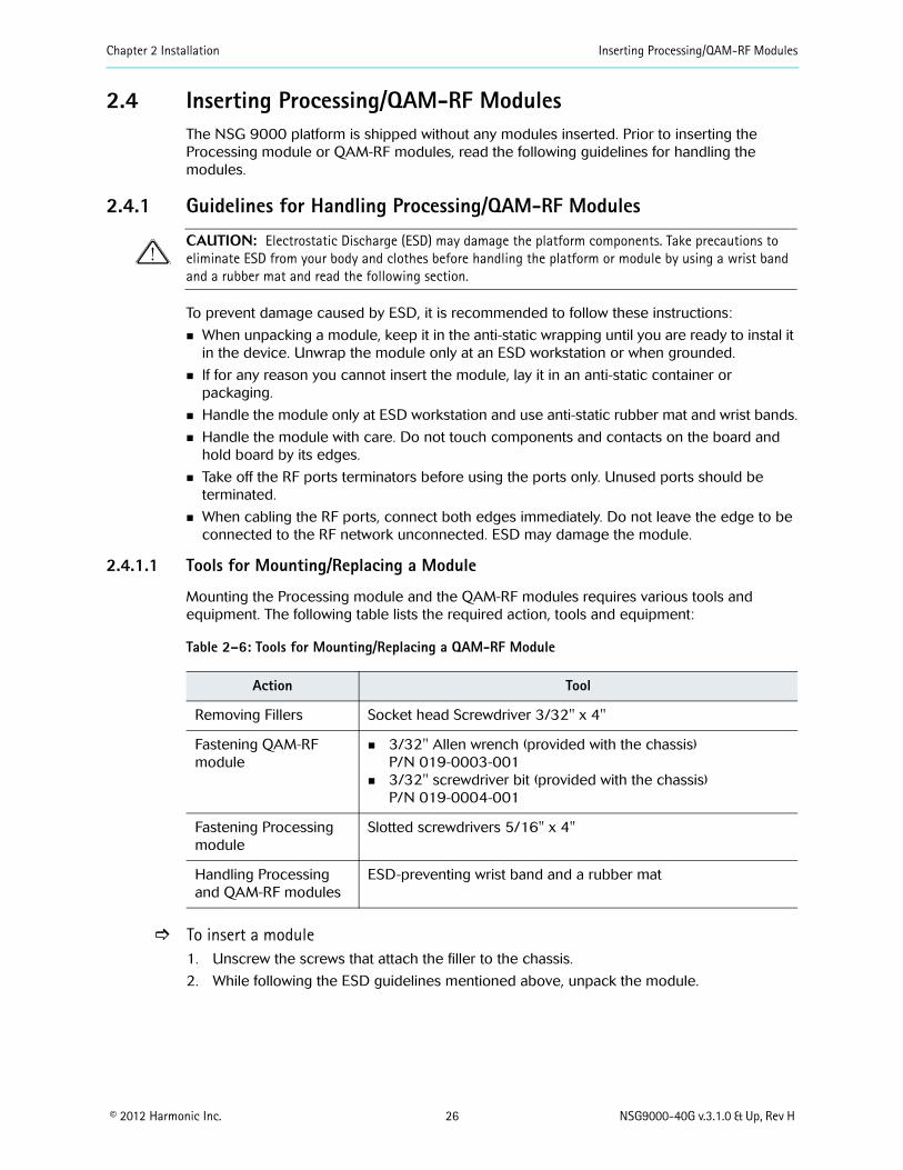
2.4 Inserting Processing/QAM-RF ModulesThe NSG 9000 platform is shipped without any modules inserted. Prior to inserting the Processing module or QAM-RF modules, read the following guidelines for handling the modules.
2.4.1 Guidelines for Handling Processing/QAM-RF Modules
CAUTION: Electrostatic Discharge (ESD) may damage the platform components. Take precautions to eliminate ESD from your body and clothes before handling the platform or module by using a wrist band and a rubber mat and read the following section.
To prevent damage caused by ESD, it is recommended to follow these instructions:
When unpacking a module, keep it in the anti-static wrapping until you are ready to instal it in the device. Unwrap the module only at an ESD workstation or when grounded.
If for any reason you cannot insert the module, lay it in an anti-static container or packaging.
Handle the module only at ESD workstation and use anti-static rubber mat and wrist bands.
Handle the module with care. Do not touch components and contacts on the board and hold board by its edges.
Take off the RF ports terminators before using the ports only. Unused ports should be terminated.
When cabling the RF ports, connect both edges immediately. Do not leave the edge to be connected to the RF network unconnected. ESD may damage the module.
2.4.1.1 Tools for Mounting/Replacing a Module
Mounting the Processing module and the QAM-RF modules requires various tools and equipment. The following table lists the required action, tools and equipment:
To insert a module1. Unscrew the screws that attach the filler to the chassis.
2. While following the ESD guidelines mentioned above, unpack the module.
Table 2–6: Tools for Mounting/Replacing a QAM-RF Module
Action Tool
Removing Fillers Socket head Screwdriver 3/32" x 4"
Fastening QAM-RF module
3/32" Allen wrench (provided with the chassis) P/N 019-0003-001
3/32" screwdriver bit (provided with the chassis)P/N 019-0004-001
Fastening Processing module
Slotted screwdrivers 5/16" x 4"
Handling Processing and QAM-RF modules
ESD-preventing wrist band and a rubber mat

Chapter 2 Installation Inserting Processing/QAM-RF Modules
© 2012 Harmonic Inc. 27 NSG9000-40G v.3.1.0 & Up, Rev H
3. While holding the module by its edges, insert it into the slot. Make sure that the sides of the module slide into the guides of the slot.
Figure 2–1: Inserting a QAM-RF Module (to be updated)
4. Push the module until its edge-connector mates securely with the connector in the slot. See 1.5.2.2 QAM-RF Modules on page 19.
5. Fasten the screws of the module to secure the module to the chassis.
Figure 2–2: Secure QAM-RF Module (picture to be updated)
6. Using the Web client, or management system, assign the module.
NOTE: To ensure proper cooling of the device, install a filler panel in any unoccupied slot. This applies equally to QAM-RF module slots and to Power Supply slots.
To replace a module
Slot’s guides

Chapter 2 Installation Inserting Processing/QAM-RF Modules
© 2012 Harmonic Inc. 28 NSG9000-40G v.3.1.0 & Up, Rev H
1. After disconnecting the RF ports, terminate them with the port terminators.
Figure 2–3: QAM-RF Terminator
2. Unscrew the screws that attach the module to the chassis.
Figure 2–4: Unscrewing the QAM-RF Module (picture to be updated)
3. Hold the module by its knob-holders and pull it out of the slot.
Figure 2–5: Module Knob Holders (picture to be updated)
4. Hold the module by its edges and lay it in an anti-static container or packaging.
QAM-RF port terminator
Module knob-holders

Chapter 2 Installation Inserting Processing/QAM-RF Modules
© 2012 Harmonic Inc. 29 NSG9000-40G v.3.1.0 & Up, Rev H
5. To insert another module, see ] To insert a module on page 26, Step 2.
To replace the Processing module:1. Unscrew the screws that attach the Processing module to the chassis in a synchronized
manner.
Figure 2–6: Processing Module
2. Pull the processing module out of its slot and place it in an anti-static container or packaging.
Figure 2–7: Replacing Processing Module (picture to be updated)
3. While following the ESD guidelines mentioned above, unpack the Processing module to be installed in the device.
4. While holding the module by its edges, insert it into the slot.
5. Push the module until its edge-connectors mate securely with the connectors in the slot.
6. In a synchronized manner, fasten the screws of the module to secure the Processing module to the chassis.
Unscrew in a synchronized manner

© 2012 Harmonic Inc. 30 NSG9000-40G v.3.1.0 & Up, Rev H
Chapter 3Cabling
The Cabling chapter guides you on how to connect the GbE, QAM-RF and Ethernet ports. Connecting cables to the NSG 9000 platform is straightforward. The NSG 9000 ports are clearly marked on the NSG 9000 back panel. See 1.5 Back Panel on page 15 for placement.
The Cabling chapter also includes device dimensions to allow better planning of the rack cabling scheme:
3.1 Device Dimensions on page 31
3.2 Cabling the GbE Ports on page 32
3.3 Connecting the QAM-RF Output Cables on page 32
3.4 Connecting the Ethernet Cables on page 33
3.5 Cabling the DTI Ports on page 33
3.6 Connecting the ASI Monitoring Port Cables on page 33
3.7.1 Grounding the Mounted Devices on page 33
3.7.2 Connecting to the Power Outlet on page 34

Chapter 3 Cabling Device Dimensions
© 2012 Harmonic Inc. 31 NSG9000-40G v.3.1.0 & Up, Rev H
3.1 Device DimensionsDimensions are provided in Inches and millimeters as follows:[inch]mm
Figure 3–1: NSG9000-40G Dimensions
3.1.1 Back Panel Measurements
Figure 3–2: NSG9000-40G Back Panel Measurements
86.13.39
580.422.85
528.320.80
0.9825.0
442.017.40
22.87580.8
27.81.09
88.13.47
482.619.00
19.4mm
50.0mm

Chapter 3 Cabling Cabling the GbE Ports
© 2012 Harmonic Inc. 32 NSG9000-40G v.3.1.0 & Up, Rev H
3.2 Cabling the GbE PortsTo connect the GbE port to the GbE switch, use either of the following:
Multimode or single-mode optic fiber with an LC connector. The LC connector plugs into an SFP receptacle and accommodates two fibers, one for transmission and the other for reception.
Shielded and grounded CAT-6 or CAT-7 cable with an RJ-45 connector. The RJ-45 connector plugs into a copper SFP receptacle.
To cable the GbE ports
1. Insert the SFP modules into the required ports at the back of the NSG 9000.
2. Insert the LC/RJ-45 plugs into the SFP module.
3. Connect the NSG 9000 to a switch or other NSG 9000 as appropriate for your network configuration.
3.2.1 Mirroring a GbE Input PortThe NSG 9000 unit may duplicate the incoming content of any GbE input port to any GbE port that is defined as a mirroring port. See, NSG 9000 Software User’s Guide.
Once a port is defined as a mirroring port, connect it to devices that accept GbE input.
To connect a mirroring port
1. Insert the SFP modules into the required receptacles at the back of the NSG 9000.
2. Insert the LC/RJ-45 plugs into the SFP module or RJ-45 cage.
3. Connect the NSG 9000 to any device with GbE interface with an RJ-5 connector such as an IP analyzer.
3.3 Connecting the QAM-RF Output Cables The NSG 9000 device accommodates up to nine modules with two QAM-RF ports for each module. The ports are labeled RF 1and 2 and implement the dual upconverter technology. Each port delivers up to eight RF channels.
When cabling the QAM-RF ports, use either of the following cables:
RG-6 (75 Ohm, 0-3 GHz) coaxial cable equipped with F-type connectors only
RG-59 (75 Ohm, 0-3 GHz) coaxial cable equipped with F-type connectors only
NOTE: The female F-type connectors are designed to accept cables with center pin diameter of 0.68-1.73 mm (0.026"- 0.068"). Cables that do not meet this requirement must be mounted with crimp-on connector of the required dimensions.
CAUTION: Using cables other than the cables indicated above may adversely affect the QAM-RF performance.
To connect the RF Cables:
1. Remove the terminators that cover the RF port.
2. Connect the cable to the RF port.
3. Connect the other edge of the cable to your output equipment according to your network schema.
CAUTION: Failing to perform step 3 and having a loose edge of the RF cable, exposes the QAM-RF module to ESD and may severely damage the QAM-RF module.

Chapter 3 Cabling Connecting the Ethernet Cables
© 2012 Harmonic Inc. 33 NSG9000-40G v.3.1.0 & Up, Rev H
3.4 Connecting the Ethernet CablesThe Ethernet ports, labeled ETH1 and ETH2, provide access to two independent networks. The required cables are shielded and grounded CAT-5E cables with RJ-45 connectors.
To connect the Ethernet cables:
Connect an Ethernet cable with RJ-45 connectors from the ETH1 port on the NSG 9000 to your management network hub or switch.
3.5 Cabling the DTI PortsCabling the DTI card is straightforward. See 1.5 Back Panel on page 15 for placement.
For connecting the DTI ports to the DTI server, use the following cables:
Shielded and grounded CAT-5E or CAT 6 cables with RJ-45 connectors.
To connect the DTI cables:
Connect one side of the DTI cable to a DTI port on the NSG 9000 back panel and the other side of the DTI cable to the DTI server.
3.6 Connecting the ASI Monitoring Port Cables The ASI output port for the NSG 9000 provides a method to monitor the device’s output data.
To connect the ASI output cable:
Connect the ASI cable with a BNC connector from the ASI output port on the NSG 9000 back panel to a device such as an MPEG analyzer.
3.7 Connecting PowerThe NSG 9000 comes with either an AC power supply or a –48 VDC power supply. Follow the instructions appropriate to your power supply.
NOTE: Reliable earthing of rack-mounted equipment should be maintained. Particular attention should be given to supply connections other than direct connections to the branch circuit.
3.7.1 Grounding the Mounted DevicesEach device should be grounded using the ground terminal on the back panel of the device. For grounding a device use a non terminated 12 AWG copper wire.
To ground each mounted device:
1. Connect one edge of the grounding wire to the Rack grounding terminal.
2. Connect the other edge of the grounding wire to the device grounding terminal by inserting the wire into the grounding terminal and fastening the screws of the grounding terminal.

Chapter 3 Cabling Boot-Up Sequence
© 2012 Harmonic Inc. 34 NSG9000-40G v.3.1.0 & Up, Rev H
3.7.2 Connecting to the Power Outlet
3.7.2.1 Power cord rating
Harmonic ships the AC power supply of the NSG with a power cord of the required rating. Customers who choose to use a different type of cord due to various considerations or constraints should use an AC cord that meets the following rating:
Current rating - 16 Amp or higher
Wire gage - 18 AWG or thicker
3.7.2.2 Connecting the NSG to the Power Supply
Connection the NSG to the AC power supply - After verifying that a proper AC power cord is being used, connect the power cord to the power connector on the NSG 9000 back panel, and to the power outlet of the rack.
The recommended line cord is 16A/18 AWG.
CAUTION: Use the recommended 16A/18AWG cord to ensure your own personal safety and to help protect the device and working environment from potential damage.
The power supply automatically senses the input voltage.
Connecting the –48 VDC Power Supply - If your NSG 9000 has the optional –48 VDC power supply, see Wiring the –48 VDC Power Supply on page 40 for instructions to wire the power supply.
3.8 Boot-Up SequenceWhen you connect the NSG 9000 to the power supply, the boot up procedure starts. During boot up the following messages appear in the control panel display:
Uboot@9600bps - indicates the first stage of the boot up procedure
Kernel Boot - indicates the second stage of the boot up procedure
Gbe. Init. - indicates the third stage, loading the application
Once boot up is complete the Power Up screen appears in the control panel display and you may start configuring the device. The Power Up screen shows the type of device and a default IP address:
.
CAUTION: Once you power up the device, the QAM-RF ports should always be connected as explained in 3.3 Connecting the QAM-RF Output Cables on page 32 or else terminated.
NOTE: The unit may have more than one power supply cord. To protect against electric shock, disconnect all power supply cords before servicing.

Chapter 3 Cabling Establishing Ethernet Connection
© 2012 Harmonic Inc. 35 NSG9000-40G v.3.1.0 & Up, Rev H
3.9 Establishing Ethernet ConnectionBecause the NSG 9000 is configured and controlled by a remote management system, you must set the IP addresses of the Ethernet ports located on the back panel of the NSG 9000. For further information, see NSG 9000-40G Software User’s Guide.
NOTE: The NSG 9000-40G requires a user name and password to log in to all management interfaces, including the serial communications console, web client and FTP. Both user name and password are configure.
3.9.1 What’s Next...The next step is to set preliminary configuration to the NSG 9000, as described in the NSG 9000-40G Software User Guide.

© 2012 Harmonic Inc. 36 NSG9000-40G v.3.1.0 & Up, Rev H
Chapter 4Maintenance
This chapter contains service information that explains how to replace the following components of the platform:
Cooling fans unit
power supply
NOTE: To prevent body injury when servicing this unit in a rack, you must take special precautions to ensure that the system remains stable.
4.1 Cooling Fans UnitThe NSG 9000 uses four fans to control the temperature of the platform during operation. All four fans are mounted on the back side of the front panel to allow a quick and easy hot swap in case of a fan failure.
Figure 4–1: Fan Unit
NOTE: A failure of a single fan, requires the replacement of the front panel of the platform.
4.1.1 Removing and Replacing the Cooling Fans UnitThe design of the device allows a quick hot swap of the fans. Removing and replacing the fans does not affect the device operation and should last not more than two minutes. If it exceeds two minutes, the device may be damaged.
4.1.1.1 Preparation
For removing and replacing the fans, you need the following:
Phillips screwdriver
A new front panel

Chapter 4 Maintenance Cooling Fans Unit
© 2012 Harmonic Inc. 37 NSG9000-40G 3.1.0 & Up, Rev H
1. Unscrew all four screws that attach the front panel to the platform. The screws are located on both sides of the front panel. Refer to the figure below.
2. Detach the front panel from the working device.
Figure 4–2: Detaching Front Panel
3. Push the new front panel to snap on the chassis and to allow the mating connector to mate securely with the connector on the chassis.
4. Screw the front panel to the working device.
5. Verify that the alarm Fan Failure is remitted.
NOTE: It is recommended to replace the front panel after five years of continuous operation. To order a front panel, use the following part number: NSG-FP-SPR-01-01L.
Screws that attach front panel to device

Chapter 4 Maintenance Hot Swapping Power Supply Unit
© 2012 Harmonic Inc. 38 NSG9000-40G 3.1.0 & Up, Rev H
4.2 Hot Swapping Power Supply UnitThe device uses two hot swappable power supply units manufactured by Telkoor or Tectrol. The following procedure guides you on how to hot swap a power supply unit assuming that both power supply units are mounted in the platform.
Figure 4–3: NSG9000-40G Power Supply Units
CAUTION: You must disconnect the power cord before removing the power supply.
1. Verify that the functioning power supply unit is connected to the main.
2. Disconnect the power cord of the malfunctioning power supply unit.
3. Turn the locking knob counter-clock wise to unlock the latch.
4. While holding on to the handle of the unit, pull it to disconnected it from the device.
5. Pull the power supply unit until the unit comes out of the platform.
Figure 4–4: Pulling Out Power Supply
6. Hold the new unit in its handle and slide it into the slot.
7. Push the unit until its edge-connector mates securely with the connector in the slot.
Power Supply unit Handle
Locking knob Grounding terminal
Power Supply unit Handle
Grounding terminal
Locking knob
Telkoor power supply unit Tectrol power supply unit
Pull the power supply unit until it comes out.

Chapter 4 Maintenance Hot Swapping Power Supply Unit
© 2012 Harmonic Inc. 39 NSG9000-40G 3.1.0 & Up, Rev H
8. Turn the locking knob clock wise to lock the latch.
9. Connect the power cord to the unit and to the wall outlet.
10. Verify that the unit is on and operating properly by checking its LEDs as explained in 1.5.3 Power Supply on page 20.
NOTE: In case only one power supply unit is mounted, install a filler panel in the slot of the unoccupied power supply unit to allow proper air flow.

© 2012 Harmonic Inc. 40 NSG9000-40G v.3.1.0 & Up, Rev H
Appendix AWiring the –48 VDC Power Supply
If your NSG 9000 uses the –48 VDC power supply, follow these steps to wire the power supply.
A.1 Getting StartedBefore you begin wiring the –48 VDC power supply, make sure that you provide the necessary overcurrent protection, wires, and power connector.
A.1.1 Power Source SpecificationsThe DC power source feeding the NSG 9000 device must meet the following requirements:
Electrically isolated from any AC power source
Positive ground. The Positive bus of the DC power source must be reliably connected to the Ground bus.
Each feed-pair must provide a continuous supply of power that meets the following specifications:
NOTE: For information on overcurrent, see 2.2.5.2 Overcurrent protection on page 24.
A.2 Wiring RequirementsThe NSG 9000 is connected to the DC power source using three wires:
–Vin
GND
+Vin
Although Harmonic provides the power input connector with the NSG 9000, you must supply the wires.
Table A–1: Feed-pair Power Supply Specifications
Parameter Power Supply Specification
Voltage NSG-PS-DC-03NSG-PS-DC-04
42 - 60VDC
Max. operating current NSG-PS-DC-03 21A
NSG-PS-DC-04 16A

Appendix A Wiring the –48 VDC Power Supply Wiring Requirements
© 2012 Harmonic Inc. 41 NSG9000-40G v.3.1.0 & Up, Rev H
The wires to be used must comply with the following specifications:
A.2.1 Power ConnectorThe NSG 9000 is supplied with a special DC power connector plug that matches the DC power socket on the power supply.
This connector may be purchased directly from Harmonic. Use the following part number for ordering the connector from Harmonic: NSG-9K-ACC-DC-CONN-01.
Use only the original connector for connecting the NSG 9000 to the DC power source. Contact Harmonic Technical Support if you want to use any other type of connector.
The following figure shows the connector with its hood removed::
Figure A–1: DC Connector
Table A–2: DC Wiring Specifications
Parameter Specification
Suitable conductor material Copper only
–Vin and +Vin wires 12 AWG rating
Grounding cable 12 AWG rating
Cable insulation rating Minimum 80 C, low smoke fume (LSF), flame retardant
Cable type Must comply with at least one of the following standards: UL 1581 (VW-1) - UL style 1028 or equivalent EEE 383 EEE 1202-1991
Branch circuit cable insulation color
Per applicable national electrical codes
Grounding cable insulation color
Green-yellow

Appendix A Wiring the –48 VDC Power Supply Assembling the DC Input Power Cable
© 2012 Harmonic Inc. 42 NSG9000-40G v.3.1.0 & Up, Rev H
A.3 Assembling the DC Input Power Cable To assemble the DC input power cable:
1. Prepare the power wires as specified in A.2 Wiring Requirements on page 40.
2. Use the disconnect device to make sure that the power supply from the DC power source to the cables is switched off.
CAUTION: Turn off the power before proceeding with these instructions.
3. Unpack the power connector.
4. Identify the three wires coming from the DC power source that are used in the connection to the expansion unit:
–Vin
+Vin
GND
5. Strip up to 0.3 inches (8 mm) of insulation from each of the wires coming from the DC power source.
NOTE: Do not strip more than this length from each wire. Stripping more leaves uninsulated wire exposed outside the DC connector after the assembly is complete.
6. Remove the connector hood.
7. Feed the exposed section of the wires into the matching hole in the DC plug connector. See step 1 in the following illustration.
8. Fasten the screws to hold securely the wires. See step 2 in the following illustration.
Figure A–2: Assembling the DC Input Power Cable
9. Place the connector hood back to its place and fasten its screws.
Pin 1: VINPin2: -VIN Pin 3: chassis ground

Appendix A Wiring the –48 VDC Power Supply Connecting the Power Cable to the NSG 9000
© 2012 Harmonic Inc. 43 NSG9000-40G v.3.1.0 & Up, Rev H
A.4 Connecting the Power Cable to the NSG 90001. Ensure the NSG 9000 is securely installed in a rack and in a Restricted Access Location
only.
2. Verify that the NSG chassis is properly grounded, as explained in 3.7.1 Grounding the Mounted Devices on page 33.
3. Connect the DC input power cable to the DC connector on the NSG 9000 back panel, as the following figure illustrates:
4. Place the Safety bracket on the DC connector as the following figure illustrates:
NOTE: The Safety bracket is not required for power supply units with the following part number:NSG-PS-DC-03 and NSG-PS-DC-04.
5. Attach the Safety bracket to the chassis by fastening the Safety bracket screw.
Grounding terminal
DC connector and power cable
DC connector inside NSG 9000 power supply
Safety bracket
Appendix A Wiring the –48 VDC Power Supply Connecting the Power Cable to the NSG 9000
© 2012 Harmonic Inc. 44 NSG9000-40G v.3.1.0 & Up, Rev H
Your NSG 9000 is now connected to power.
6. Complete any other cabling that may still be needed, and engage the disconnected device to start using the device.

Harmonic Inc.4300 North First StreetSan Jose, CA 95134 U.S.A.T +1 408 542 2500 F +1 408 542.2511
www.harmonicinc.com
© Copyright 2007 Harmonic Inc. All rights reserved.Manual Part No. 700-000XXXX