nstx tf flag joint review analysis & design c neumeyer 9/3/3
TRANSCRIPT

NSTX TF Flag Joint Review
ANALYSIS & DESIGN
C Neumeyer9/3/3

Topics• Backround• Requirements• Forces and Load Paths • Thermal Effects• Contact Resistance• Features of New Design• Performance of New Design

BACKGROUND
• TF joint failed on February 14, 2003 due to structural weaknesses
• Project has developed a more robust design.......
– factor in lessons learned from failure
– all engineering aspects analyzed at appropriate level of detail
– testing as necessary for engineering input and design verification
– reduced dependence on precision manufacturing/assembly
– easier maintenance

Failure2/14
FailureAnalysis
ConceptScopingStudies
Drawings
FEA
PrototypeMechanical
Testing
PrototypeElectricalTesting
DesignReview4/10
Testing
ComponentTests
Design Integration
Conductor Machining
Inner LegFabrication
& Assy
PPPLActivity
Certification Committee
Lessons Learned
Review PanelReport
DesignReview
8/7
Resume Operations
Design Finalization
LehmanReview
9/3
RECOVERY ACTIVITIES

DESIGN3D modeling complete, including…
integrated TF inner leg bundle coolant tube routing and bulkhead outer leg connections
Fabrication drawings complete, including…
conductors flags flag boxes shear shoes hub assembly torque collar*
* Under revision

ANALYSISStructural FEA complete, including…
both tiers of conductors out-of-plane load path through spline collar and wet lay-up representation in-plane, out-of-plane, thermal loads SOFT, EOFT, EOP casesVarious off-normal cases
Other analysis complete, including…
force calculations temperatures, including joint temperature rise fastener sizing calculations miscellaneous calculations
Torque Collar analysis continuing

TESTINGComponent testing (design input data) consists of:
Pull-out tests on threaded inserts - one time and cyclic at 100oC
Pull-out tests on bolts threaded in copper - one time and cyclic
Friction coefficient and electrical resistance testsShear tests on torque collar attachment
Status: Complete except more data to be generated for torque collar shear at high compression
Prototype testing (design verification) consists of:
Mechanical mock-up of single joint for cyclic fatigue testingElectrical mock-up of single joint tested at full current and I2T
Status: In Preparation

0
10
20
30
40
50
60
70
80
-1 0 1 2 3 4 5 6
6kG Full I2T L/R
108712
3kG Full I2T L/R
CURRENT WAVEFORMS• Engineering design accounts for PS response, inc’l L/R decay in case of fault from Imax
• ∫I2T = 6.0 x 10⁹ A2-s for 3kG-4.5s
• ∫I2T = 6.15 x 10⁹ A2-s for 6kG-0.6s
• Design basis ∫I2T = 6.5 x 10⁹ A2-s which causes adiabatic T of 80oC in Cu
• 6kG pulse is most critical for joint since forces are maximum and time for heat diffusion is minimum
Short Pulse
Long Pulse

NUMBER OF PULSES & THERMAL CYCLES
• Assume 50,000 pulse requirement at 6kG- 10 yr*20 week*5day*8hr*6pulse/hr = 48,000- Highly conservative- NSTX 5yr plan calls for …
40% @ 3kG (25% EM load) 40% @ 4kG (44% EM load) 15% @ 5kG (69% EM load) 5% @ 6kG (100% EM load) 100%
• Assume 1,000 thermal ratcheting cycles (= number of days)- 10 yr*20 week*5day = 1000- drives flag fastener fatigue cycle requirement- assuming 12 pulse/hr rate to set thermal ratcheting (conservative)

EM FORCES
• In-Plane-vertical load and momentdue to magnetic pressure from self-field
• Out-of-Plane-lateral due to ItfxBz(oh&pf)
-torsional due to ItfxBr(oh&pf)
9.3klb
2.3klb
4.7klb
3klb
148kft-lb
40.8kft-lb
Notes: 1) All coils assumed at full current, worst case polarity (conservative)2) Forces equal and opposite on two ends of bundle

FUNCTIONS OF JOINTMechanical FunctionMechanical Function
Preload for High Contact Pressure
Structural Support Against EM & Thermal Loads
Maintain High Contact Pressure
Low Electrical Resistance and Dissipation
Peak Temperature within Limit
Electrical FunctionElectrical Function

LOAD PATHS
1) Friction2) Shear Shoe3) Torque Collar4) Hub/Spline/VV
Spline JointUmbrellaOuter LegFlexHubFlagVesselAnchorTorque CollarWet Lay-upInner Leg BundleFEMShearShoe

THERMAL EFFECTS•Vertical length of inner leg bundle from bottom to top increases by up to 0.35” during a pulse
•Vertical length of inner leg from torque collar to top of bundle increases due to inner leg temperature rise, whereas flag and hub remain relatively cool
•Radius of inner leg bundle increases bundle increases by approximately 0.006” during a pulse
•Flag heats modestly during pulse (T ≈ 5oC) but can ratchet to T ≤25oC at rated duty cycle (conservative), r ≈ 0.005” in length

CONTACT RESISTANCEFlat Top Time to Limit Max Temperature
at Joint to 120 C 71 KA Waveform, L/R Decay
0.2
0.3
0.4
0.5
0.6
0.7
0.8
0.9
1.0
0 1 2 3 4 5 6 7 8
Contact Resistance, μΩ- 2in
, Flat top sec
120 C Liμit at Joint~80 C Liμit in Turn
Req’d Flat Top Time=0.6 sec
TolerableResistivity≈ 2.5µΩ-in2
(700psi)
Note: assuming constant resistivity along joint
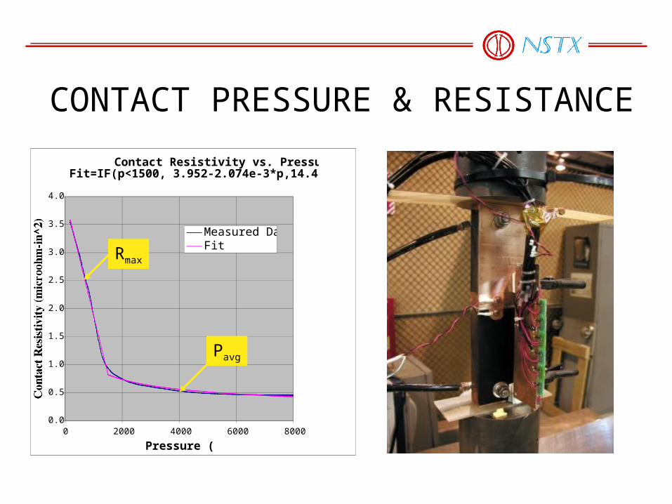
CONTACT PRESSURE & RESISTANCE
Contact Resistivity vs. Pressure, Fit=IF(p<1500, 3.952-2.074e-3*p,14.482*p^-0.392)
0.0
0.5
1.0
1.5
2.0
2.5
3.0
3.5
4.0
0 2000 4000 6000 8000
Pressure (psi)
Contact Resistivity (microohm-in^2)
Measured DataFit
Rmax
Pavg

KEY DESIGN FEATURES
Flag
Flag bolts (studs)
Shear Shoe
Flag Box
Box Bolts (stud)Torque Collar
Hub Disks

TORQUE COLLAR
Prior Design (August 7)-not vertically symmetric-Torque reacted through moment arm
New Design-vertically symmetric-torque reacted tangentially

VOLTAGE PROBES FOR IN-SITU JOINT RESISTANCE MEASUREMENT
• IDI 100526 Coaxial Probe - commercial spring-loaded probe used in semiconductor test industry-2 probes per flag, 1 connected to instrumentation, 1 redundant spare-All 72 joints monitored (maintenance @ 200A, real time at full current)

DESIGN HIGHLIGHTS• Solid (not split) flags insulated with 4 layers Kapton, glass wrapped, potted in 304SS boxes
• Boxes attached to hub disks using 1/2” studs
• Flags attached via 3/8” Inconel studs preloaded to 5000lbf
• Shear shoe on outer edge of flags is bolted to ends of inner leg conductor using Inconel bolts, one vertical and one angled for moment reaction
• 3-segment torque collar w/two 1/2” bolts @ 10000lbf per joint, 0.180” wet lay-up with better type of epoxy (Hysol E-120HP)
• Collar transmits torque only to hub structure at 3 anchor points
• Redundant voltage probes are located on each side of the flag
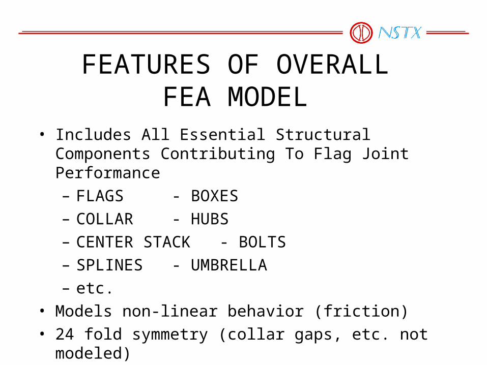
FEATURES OF OVERALLFEA MODEL
• Includes All Essential Structural Components Contributing To Flag Joint Performance
– FLAGS - BOXES
– COLLAR - HUBS
– CENTER STACK - BOLTS
– SPLINES - UMBRELLA
– etc.
• Models non-linear behavior (friction)
• 24 fold symmetry (collar gaps, etc. not modeled)


LOAD CASES EXAMINED• Time Points
– START OF FLAT TOP (SOFT)
– END OF FLAT TOP (EOFT)
– END OF PULSE (EOP)
• Conditions– Normal
– Off NormalLow Preload (60%)High Friction CoefficientLow Friction Coefficient

FEA USED TO ASSESS STRESSES, DISPLACEMENTS, CONTACT PRESSURES

SUMMARY OF RESULTSLOAD CASE < 1000 PSI LOST CONTACTEOFT-0.4 f 8% <1%
EOFT-0.2 f 0% 0%
EOFT-0.0 f 0% 0%
SOFT-0.4 f 9% 4%
SOFT-0.6 f 11% 8%
SOFT-0.4 f(3000 lbs/bolt)
20% 14%
EOP 0% 0%

Temperatures Well Below Limit of 120oC
Contact Region
Max Temperature of 94oC Occurs Just After EOFT
• Tflat = 0.7sec (vs. 0.6 req’t)• Bolt Holes not exactly modeled (+10oC)• OH constant at max current (-TBDoC)• Insignificant change from constant resistivity simulation

OFF-NORMAL CASE: 60% PRELOAD
Normal
• Peak Temperature ≈ 3oC Higher
• Temperature Distribution Different
• Current Redistribution Beneficial
Notes:1) Held SOFT pressure conditions after
SOFT due to lack of EOFT data2) Color scales different
Off-Normal

TORQUE COLLAR FEA
Detailed analysis of prior design revealed high stressconcentrations in wet lay-up due to lack of vertical symmetry

NEW TORQUE COLLAR FEA
-preliminary results indicate adequate safety margins-work still in progress

DESIGN MARGINS
Component Material
Max Load (lbf)
Max Stress (psi)
Yield Stress (psi)
Safety Factor on
Yield
Failure Stress (psi)
Safety Factor on Failure
Flag Studs Inconel 718 5755 74268 185000 2.49 210000 2.83
Insert pullout Copper 5755 13573 19412 1.43 23152 1.71
Shear Shoe Bolt A286 5279 68125 102000 1.50 146000 2.14
Shear Shoe Bolt pullout Copper 5279 11971 18701 1.56 22713 1.90
Wet Lay-up Peak Shear (Combined) Hysol n.a. TBD TBD TBD
Collar Bolts Inconel 718 10000 70473 185000 2.63 210000 2.98
Box Bolts 304SS 3695 23101 31200 2.16 73200 5.97
Box Bolt Pullout 304SS 3695 5324 15600 2.93 36600 6.87
Box Friction 304/304 4700 1.84

DESIGN IMPROVEMENTSFeature Old Design New Design
Hub Stiffness Not adequate; lacking stiff linkages between disks because flags could slide w.r.t. disks
Very stiff. Boxes form webs with disks like I-beams
Flag Bolts/Studs
Shoulder engagement was too small Shear Shoe using two 3/8” dia bolts
5/16” Bolt thread necked down too far, shank not necked down, not compliant for thermal cycling
3/8” Studs necked down to root diameter, belleville washers
Torsion in long bolts during tightening, inaccurate tensioning
Studs with nuts used in place of long bolts, stud tensioner
Dual purpose bolts, combined tension and shear functions, tolerance issues
Loose fitting clearance holes for studs, separate shear shoes
Four 5/16" bolts @ 2500#, marginal friction to carry shear
Four 3/8" studs @ 5000#, doubling of preload
Thin washers under bolt heads 1/4" thick washer plate over Belleville washers

All defects contributing to original failure have been addressed
Feature Old Design New Design
Inserts Keensert type, marginal thread engagement Taplok type, thread engagement > 0.5"
Shimming Manually selected and inserted G10 shim stock Hysol/glass tape potting in boxes, mold released to permit thermal growth
Out-of-Plane Load Path
Wedged G10 blocks with pusher bolts Flags potted in boxes, boxes bolted to hub disks
Torque Collar Two piece collar bolted directly to hub. Wet lay-up 0.25” thick Hysol RE2039 & HD3561. Holes in collar for epoxy outflow to enhance adhesion.
Three piece collar with sliding contact with hub for torsion-only connection. Wet lay-up 0.180” thick Hysol E-120HP (improved adhesive strength). Serrations in collar to enhance adhesion.
Joint Resistance Measurement
10A Biddle measurement via connection to two half flags on disassembled joint, 1µΩ resolution
200A precision measurement using voltage taps in situ, ≈ 20x enhanced resolution, plus real time measurement every pulse

CONCLUSIONS•New Design Corrects All Defects Associated with Original Design
•New Design Has Sufficient Margins at 6kG (pending torque collar resolution)
• Follow-on Activities Will Increase Confidence
Mechanical Prototype Testing
Electrical Prototype Testing
Instrumentation During Commissioning and Operations
- resistance measurement (200A maintenance and real-time) system- temperature, strain, displacement)