ntc thermistors - ge measurement & control
TRANSCRIPT
WHAT IS A THERMISTOR
A thermistor is an electronic component thatexhibits a large change in resistance with a changein its body temperature. The word “thermistor” isactually a contraction of the words “thermal resistor”.
The thermistors that we shall describe herein areceramic semiconductors and have either large positive temperature coefficient of resistance (PTCdevices) or large negative temperature coefficient ofresistance (NTC devices). Both types of thermistors(PTC and NTC) have definite features and advantages which make them ideal for certain sensor applications.
NTC THERMISTORS
The NTC thermistors which are discussed hereinare composed of metal oxides. The most commonlyused oxides are those of manganese, nickel, cobalt,iron, copper and titanium. The fabrication of commercial NTC thermistors uses basic ceramicstechnology and continues today much as it has fordecades. In the basic process, a mixture of two ormore metal oxide powders are combined with suitable binders, are formed to a desired geometry,dried, and sintered at an elevated temperature. Byvarying the types of oxides used, their relative proportions, the sintering atmosphere, and the sintering temperature, a wide range of resistivitiesand temperature coefficient characteristics can be obtained.
Types of NTC Thermistors
Commercial NTC thermistors can be classifiedinto two major groups depending upon the methodby which electrodes are attached to the ceramicbody. Each group may be further subdivided intovarious types of thermistors where each type is characterized by differences in geometry, packagingand/or processing techniques.
The first group consists of bead type thermistors.All of the bead type thermistors have platinum alloyleadwires which are directly sintered into theceramic body. Bead type thermistors include the following:
• Bare Beads• Glass Coated Beads• Ruggedized Beads• Miniature Glass Probes• Glass Probes• Glass Rods• Bead-in-Glass Enclosures
The second group of thermistors have metallizedsurface contacts. All of these types are availablewith radial or axial leads as well as without leads forsurface mounting or mounting by means of springcontacts.
Metallized surface contact thermistors includethe following:
• Disks• Chips (Wafers)• Surface Mounts• Flakes• Rods• Washers
NTC thermistors are available in a wide variety ofconfigurations and protective coatings to suit almostany application. The most stable and accurate ther-mistors available are those which are hermeticallysealed in glass. Hermetically sealed thermistors arealso used, almost exclusively, for applications thatrequire continuous exposure to temperatures above150°C.
Fabrication of Bead Type Thermistors
Bead type thermistors are normally fabricated byapplying a small dab of a slurry of mixed metaloxides with a suitable binder onto a pair of spacedplatinum alloy leadwires. When the proper binder isused, surface tension draws the material into a bead that has the shape of an ellipsoid. The leadwires are strung in a fixture that applies a slightamount of tension to them and carefully controls thespacing between the wires. After the mixture hasbeen allowed to dry, or has been partially sintered,the strand of beads is removed from the fixture andsintered. During the sintering, the thermistor oxidesshrink about the platinum alloy wires to form intimate electrical and mechanical bonds.
NTC THERMISTORS
BOWTHORPE THERMOMETRICS THERMOMETRICS, INC. KEYSTONE THERMOMETRICS CORPORATIONCrown Industrial Estate, Priorswood Road 808 US Highway 1 967 Windfall Road
Taunton, Somerset TA2 8QY UK Edison, New Jersey 08817-4695 USA St. Marys, Pennsylvania 15857-3397 USATel +44 (0) 1823 335200 Tel +1 (732) 287 2870 Tel +1 (814) 834 9140Fax +44 (0) 1823 332637 Fax +1 (732) 287 8847 Fax +1 (814) 781 7969
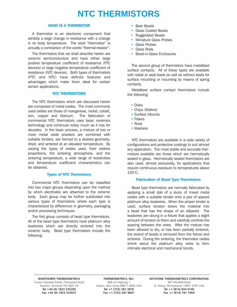
The beads are then individually cut from thestrand in one of the desired lead configurations as shown in Figure <1>. The most common con-figurations are those that result in the adjacent andopposite cut leads. All commercial bead type thermistors have platinum alloy leads which rangefrom .0007” to .004” (0.018 mm to 0.1 mm) diameter.
Although it is possible to obtain strain relief for theleads of a bare bead with organic coatings, it is morecommon to hermetically seal such units in glass.The use of an hermetic seal provides about a ten-fold improvement in the stability of a thermistor.Common glass structures are shown in Figure <2>.
Figure 1: NTC Bead strands
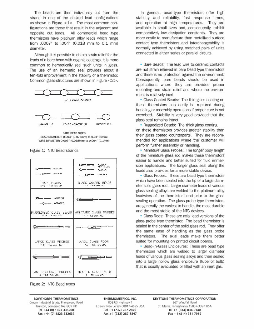
Figure 2: NTC Bead types
In general, bead-type thermistors offer high stability and reliability, fast response times, and operation at high temperatures. They are available in small sizes and, consequently, exhibit comparatively low dissipation constants. They aremore costly to manufacture than metallized surfacecontact type thermistors and interchangeability isnormally achieved by using matched pairs of unitsconnected in either series or parallel circuits.
• Bare Beads: The lead wire to ceramic contacts are not strain relieved in bare bead type thermistorsand there is no protection against the environment.Consequently, bare beads should be used in applications where they are provided propermounting and strain relief and where the environ-ment is relatively inert.
• Glass Coated Beads: The thin glass coating onthese thermistors can easily be ruptured during handling or assembly operations if proper care is notexercised. Stability is very good provided that theglass seal remains intact.
• Ruggedized Beads: The thick glass coatingon these thermistors provides greater stability thantheir glass coated counterparts. They are recom-mended for applications where the customer willperform further assembly or handling.
• Miniature Glass Probes: The longer body lengthof the miniature glass rod makes these thermistorseasier to handle and better suited for fluid immer-sion applications. The longer glass seal along theleads also provides for a more stable device.
• Glass Probes: These are bead type thermistors which have been sealed into the tip of a large diam-eter solid glass rod. Larger diameter leads of variousglass sealing alloys are welded to the platinum alloyleadwires of the thermistor bead prior to the glasssealing operation. The glass probe type thermistorsare generally the easiest to handle, the most durableand the most stable of the NTC devices.
• Glass Rods: These are axial lead versions of the glass probe type thermistor. The bead thermistor issealed in the center of the solid glass rod. They offerthe same ease of handling as the glass probe thermistors. The axial leads make them bettersuited for mounting on printed circuit boards.
• Bead-in-Glass Enclosures: These are bead typethermistors which are welded to larger diameterleads of various glass sealing alloys and then sealedinto a large hollow glass enclosure (tube or bulb)that is usually evacuated or filled with an inert gas.
BOWTHORPE THERMOMETRICS THERMOMETRICS, INC. KEYSTONE THERMOMETRICS CORPORATIONCrown Industrial Estate, Priorswood Road 808 US Highway 1 967 Windfall Road
Taunton, Somerset TA2 8QY UK Edison, New Jersey 08817-4695 USA St. Marys, Pennsylvania 15857-3397 USATel +44 (0) 1823 335200 Tel +1 (732) 287 2870 Tel +1 (814) 834 9140Fax +44 (0) 1823 332637 Fax +1 (732) 287 8847 Fax +1 (814) 781 7969
BARE BEAD SIZESBEAD DIAMETER: 0.003” (0.075mm) to 0.04” (1mm)
WIRE DIAMETER: 0.007” (0.018mm) to 0.004” (0.1mm)
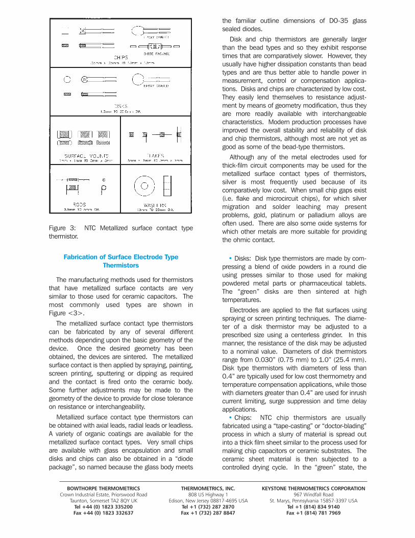
Figure 3: NTC Metallized surface contact type thermistor.
Fabrication of Surface Electrode TypeThermistors
The manufacturing methods used for thermistorsthat have metallized surface contacts are very similar to those used for ceramic capacitors. Themost commonly used types are shown in Figure <3>.
The metallized surface contact type thermistorscan be fabricated by any of several different methods depending upon the basic geometry of thedevice. Once the desired geometry has beenobtained, the devices are sintered. The metallizedsurface contact is then applied by spraying, painting,screen printing, sputtering or dipping as requiredand the contact is fired onto the ceramic body.Some further adjustments may be made to thegeometry of the device to provide for close toleranceon resistance or interchangeability.
Metallized surface contact type thermistors canbe obtained with axial leads, radial leads or leadless.A variety of organic coatings are available for themetallized surface contact types. Very small chipsare available with glass encapsulation and smalldisks and chips can also be obtained in a “diodepackage”, so named because the glass body meets
the familiar outline dimensions of DO-35 glasssealed diodes.
Disk and chip thermistors are generally largerthan the bead types and so they exhibit responsetimes that are comparatively slower. However, theyusually have higher dissipation constants than beadtypes and are thus better able to handle power in measurement, control or compensation applica-tions. Disks and chips are characterized by low cost.They easily lend themselves to resistance adjust-ment by means of geometry modification, thus theyare more readily available with interchangeable characteristics. Modern production processes haveimproved the overall stability and reliability of diskand chip thermistors, although most are not yet asgood as some of the bead-type thermistors.
Although any of the metal electrodes used forthick-film circuit components may be used for themetallized surface contact types of thermistors, silver is most frequently used because of its comparatively low cost. When small chip gaps exist(i.e. flake and microcircuit chips), for which silvermigration and solder leaching may present problems, gold, platinum or palladium alloys areoften used. There are also some oxide systems forwhich other metals are more suitable for providingthe ohmic contact.
• Disks: Disk type thermistors are made by com-pressing a blend of oxide powders in a round dieusing presses similar to those used for making powdered metal parts or pharmaceutical tablets.The “green” disks are then sintered at high temperatures.
Electrodes are applied to the flat surfaces usingspraying or screen printing techniques. The diame-ter of a disk thermistor may be adjusted to a prescribed size using a centerless grinder. In thismanner, the resistance of the disk may be adjustedto a nominal value. Diameters of disk thermistorsrange from 0.030” (0.75 mm) to 1.0” (25.4 mm).Disk type thermistors with diameters of less than0.4” are typically used for low cost thermometry andtemperature compensation applications, while thosewith diameters greater than 0.4” are used for inrushcurrent limiting, surge suppression and time delayapplications.
• Chips: NTC chip thermistors are usually fabricated using a “tape-casting” or “doctor-blading”process in which a slurry of material is spread outinto a thick film sheet similar to the process used formaking chip capacitors or ceramic substrates. Theceramic sheet material is then subjected to a controlled drying cycle. In the “green” state, the
BOWTHORPE THERMOMETRICS THERMOMETRICS, INC. KEYSTONE THERMOMETRICS CORPORATIONCrown Industrial Estate, Priorswood Road 808 US Highway 1 967 Windfall Road
Taunton, Somerset TA2 8QY UK Edison, New Jersey 08817-4695 USA St. Marys, Pennsylvania 15857-3397 USATel +44 (0) 1823 335200 Tel +1 (732) 287 2870 Tel +1 (814) 834 9140Fax +44 (0) 1823 332637 Fax +1 (732) 287 8847 Fax +1 (814) 781 7969
sheet of material is reasonably flexible and easy to handle. The dried material is then cut into slabs or squares that are stacked on ceramic setters and sintered at high temperatures. Metallized electrodes are applied by using standard spraying, screening, or dipping techniques.
The typical commercial NTC chip thermistors areavailable with cross sectional areas that range from0.010” x 0.010” (0.25 mm x 0.25 mm) up to0.120” x 0.120” (3 mm x 3 mm) and with thick-nesses that range between 0.006” (0.15 mm) and0.030” (0.75 mm). Larger size and thicker chipsare less economical to manufacture, however, theycan be available upon special order. Chips are frequently used for precision thermometry applica-tions because of their smaller sizes and fasterresponse times when compared to disks. A typicallow cost interchangeable NTC thermistor consists ofa small chip that has been attached to leads, groundto a precision resistance tolerance at a controlled temperature, and then provided with an epoxy coating for protection.
Hybrid Mount type thermistors are leadless versions of chip type thermistors. They are intendedfor mounting directly to metallized pads on hybridmicrocircuits, integrated circuits or printed circuitboards by either soldering or conductive epoxy bonding. A leadwire is then attached to the topelectrode surface to complete the electricalconnection.
• Surface Mounts: Surface mount type therm-istors are leadless, rectangular devices which caneither be formed in a die similar to disk type thermistors or they can be bladed and diced similarto chip type thermistors. Electrodes are appliedsuch that they wrap around the edges of the deviceand the body dimensions are fixed with respect toprinted circuit industry standards. Electrical connection to the circuit is accomplished either bymeans of reflow soldering or by conductive epoxybonds.
• Flakes: Flake thermistors have been fabricatedusing the “doctor blade” or “tape-casting” methodsas well as the standard screening techniques usedin the manufacture of thick-film capacitors andresistors. After sintering, electrodes are applied tothe flakes using any of the standard methods forfilm-type components. The low mass and high surface-to-mass ratio provided by flakes make theseunits ideally suited for passive infrared measure-ment.
• Rods: Rod-type thermistors are made by ex-truding a mixture of oxide powders and a suitablebinder through a die. Their greater mass, longerthermal time constants and higher dissipation
constants makes them suitable for applicationsinvolving temperature compensation, time delay orsurge suppression.
• Washers: Washer type thermistors are fabri-cated using techniques similar to those used fordisks except that a hole is formed in the center during the pressing operation. Washers are usuallyconnected to circuitry by means of spring clips orother hardware.
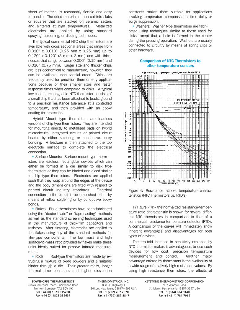
Comparison of NTC Thermistors toother temperature sensors
Figure 4: Resistance-ratio vs. temperature charac-teristics (NTC Thermistors vs. RTD’s)
In Figure <4> the normalized resistance-temper-ature ratio characteristic is shown for several differ-ent NTC thermistors in comparison to that of a commercial resistance-temperature detector (RTD).A comparison of the curves will immediately showinherent advantages and disadvantages for bothtypes of devices.
The ten-fold increase in sensitivity exhibited byNTC thermistor makes it advantageous to use suchdevices for low cost, precision temperature measurement and control. Another major advantage offered by thermistors is the availability ofa wide range of relatively high resistance values. Byusing high resistance thermistors, the effects of
BOWTHORPE THERMOMETRICS THERMOMETRICS, INC. KEYSTONE THERMOMETRICS CORPORATIONCrown Industrial Estate, Priorswood Road 808 US Highway 1 967 Windfall Road
Taunton, Somerset TA2 8QY UK Edison, New Jersey 08817-4695 USA St. Marys, Pennsylvania 15857-3397 USATel +44 (0) 1823 335200 Tel +1 (732) 287 2870 Tel +1 (814) 834 9140Fax +44 (0) 1823 332637 Fax +1 (732) 287 8847 Fax +1 (814) 781 7969
sensor lead resistance can be minimized. The non-linearity of the thermistor resistance-tempera-ture characteristics puts a practical limit on the temperature span over which a single thermistor canbe operated in a measurement or control circuit.RTD’s have lower sensitivity, are more linear and can therefore be used in application where the temperature spans are very wide.
Thermistors have other important advantagesover RTD’s in that they are available in smaller sizes,with faster response times, at lower costs and withgreater resistance to shock and vibration effects.
NTC thermistors compare very will to thermocou-ples over the limited temperature ranges where bothsensors can be effectively used for temperaturemeasurement and control. Of course, thermocou-ples will operate at much higher temperatures and over much wider spans and are available in very fine wire diameters. However, thermocoupleshave some notable disadvantages. First the thermal EMF values produced by thermocouples (thermoelelments) are on the order of a few microvolts per degree. Second, the electronic circuits used for thermocouple measurement andcontrol applications must provide high gain, lownoise amplification of the signal and provide compensation for the cold junction temperature.Third, the stability and accuracy of base metal thermocouples can be degraded by environmentalfactors and non-homogeneities. As such, NTC thermistors provide greater sensitivity, stability andaccuracy than thermocouples and can be used withless complex, less costly instrumentation.
NTC thermistors also have advantages over thesolid state sensors that are finding widespread usein direct digital temperature measurement and control applications. The solid state devices produce an output signal that is proportional to temperature over operationing ranges that fall withinthe overall range of -55° to +150°C. The solid state devices can be incorporated into applicationspecific integrated circuits for direct readout of temperatures. They exhibit accuracy and linearityspecifications in the range of ±0.3°C (selected) upto ±4°C over their published ranges. Packaging ofthe devices can take any of the standard outline dimensions for solid state devices.
The NTC thermistors, by comparison, offer bettersensitivity and accuracy over the operating tempera-ture ranges, smaller sizes with faster response timesand can be obtained in a wider assortment of device packages or sensor housings. Glass encapsulated NTC thermistors will also perform in much higher operating and storage temperaturesthan the solid state devices.
PROPERTIES OF NTC THERMISTORS
NTC thermistors have thermal and electrical properties which are important considerations ineach application. These properties are a function ofthe geometry of the thermistor, of the particular “material system” of metal oxides that is being usedand of the additional materials (electrodes, inks,solders, leadwires, etc.) that are applied to the basicdevice.
These properties and other product data are presented in the manufacturers catalogs as nominalresistance values, resistance-vs-temperature curves(tables), thermal time constant values, dissipationconstant values and power ratings.
Thermal Properties
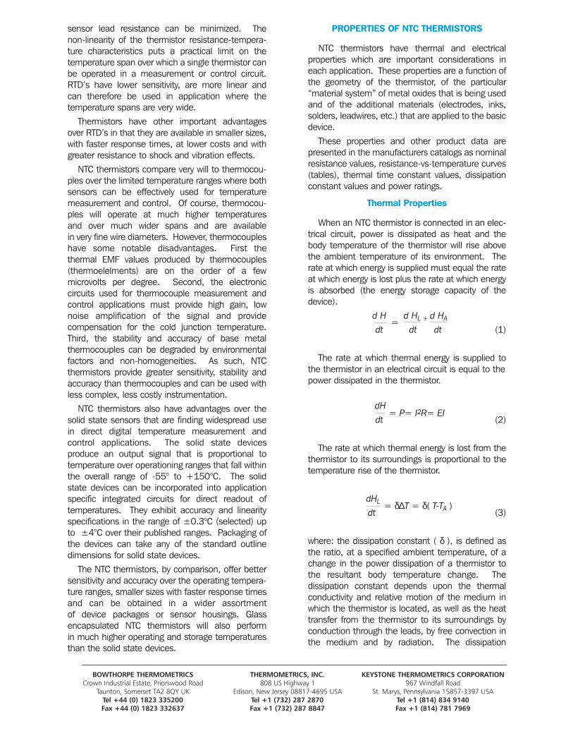
When an NTC thermistor is connected in an elec-trical circuit, power is dissipated as heat and thebody temperature of the thermistor will rise abovethe ambient temperature of its environment. Therate at which energy is supplied must equal the rateat which energy is lost plus the rate at which energyis absorbed (the energy storage capacity of thedevice).
d H d HL + d HA
dt dt dt (1)
The rate at which thermal energy is supplied tothe thermistor in an electrical circuit is equal to thepower dissipated in the thermistor.
dH dt (2)
The rate at which thermal energy is lost from thethermistor to its surroundings is proportional to thetemperature rise of the thermistor.
dHL
dt (3)
where: the dissipation constant ( δ ), is defined asthe ratio, at a specified ambient temperature, of achange in the power dissipation of a thermistor tothe resultant body temperature change. The dissipation constant depends upon the thermal conductivity and relative motion of the medium inwhich the thermistor is located, as well as the heattransfer from the thermistor to its surroundings byconduction through the leads, by free convection inthe medium and by radiation. The dissipation
BOWTHORPE THERMOMETRICS THERMOMETRICS, INC. KEYSTONE THERMOMETRICS CORPORATIONCrown Industrial Estate, Priorswood Road 808 US Highway 1 967 Windfall Road
Taunton, Somerset TA2 8QY UK Edison, New Jersey 08817-4695 USA St. Marys, Pennsylvania 15857-3397 USATel +44 (0) 1823 335200 Tel +1 (732) 287 2870 Tel +1 (814) 834 9140Fax +44 (0) 1823 332637 Fax +1 (732) 287 8847 Fax +1 (814) 781 7969
=
= P= I2R= EI
= δ∆T = δ( T-TA )
constant is not a true constant since it varies slightlywith temperature and also with temperature rise. Itis typically measured under equilibrium conditions.
The rate at which thermal energy is absorbed bythe thermistor to produce a specific amount of risein temperature can be expressed as follows:
d HA dT dT
dt dt dt (4)
where: (s) is the specific heat and (m) is the massof the thermistor. The product of the specific heatand the mass is the heat capacity (C) of the ther-mistor and is dependent upon thermistor materialsand construction. Thus, the heat transfer equationfor an NTC thermistor at any instant in time afterpower has been applied to the circuit can beexpressed as:
d H dT
dt dt(5)
In order to complete our analysis of the thermalcharacteristics of thermistors, we must examine thethermistor behavior under transient and steady stateconditions. The solution of equation (5) where thepower (P) is constant is:
P -δδ C (6)
Equation (6) demonstrates that when a significant amount of power is dissipated in a thermistor, its body temperature will rise above theambient temperature as a function of time. The transient conditions at “turn on”, and all applicationsthat are based upon the Current-TimeCharacteristics, are governed by equation (6).
A condition of equilibrium is achieved whendT/dt=0 in equation (5) or when t>>C/δ in equa-tion (6). In this steady state condition, the rate ofheat loss is equal to the power supplied to the thermistor.
Therefore:
δ( T-TA ) = δ∆T = P = ET IT(7)
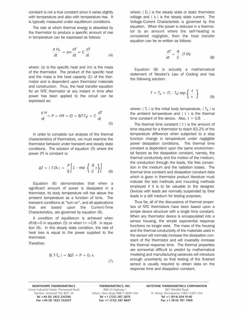
where: ( ET ) is the steady state or static thermistorvoltage and ( IT ) is the steady state current. TheVoltage-Current Characteristic is governed by thisequation. When the power is reduced in a thermis-tor to an amount where the self-heating is considered negligible, then the heat transfer equation can be re-written as follows:
dT -δdt C (8)
Equation (8) is actually a mathematical statement of Newton’s Law of Cooling and has the following solution:
-t τ (9)
where: ( TI ) is the initial body temperature, ( TA ) isthe ambient temperature and ( τ ) is the thermaltime constant of the device. Also, τ = C/δ .
The thermal time constant ( τ ) is the amount oftime required for a thermistor to reach 63.2% of thetemperature difference when subjected to a stepfunction change in temperature under negligiblepower dissipation conditions. The thermal time constant is dependent upon the same environmen-tal factors as the dissipation constant, namely, the thermal conductivity and the motion of the medium,the conduction through the leads, the free convec-tion in the medium and the radiation losses. Thethermal time constant and dissipation constant datawhich is given in thermistor product literature mustindicate the test methods and mounting methodsemployed if it is to be valuable to the designer.Devices with leads are normally suspended by theirleads in a still medium for testing purposes.
Thus far, all of the discussions of thermal proper-ties of NTC thermistors have been based upon asimple device structure with a single time constant.When any thermistor device is encapsulated into asensor housing, the simple exponential responsefunctions no longer exist. The mass of the housingand the thermal conductivity of the materials used inthe sensor will normally increase the dissipation con-stant of the thermistor and will invariably increasethe thermal response time. The thermal propertiesare somewhat difficult to predict by mathematicalmodeling and manufacturing variances will introduceenough uncertainty so that testing of the finishedsensor is usually required to obtain data on theresponse time and dissipation constant.
BOWTHORPE THERMOMETRICS THERMOMETRICS, INC. KEYSTONE THERMOMETRICS CORPORATIONCrown Industrial Estate, Priorswood Road 808 US Highway 1 967 Windfall Road
Taunton, Somerset TA2 8QY UK Edison, New Jersey 08817-4695 USA St. Marys, Pennsylvania 15857-3397 USATel +44 (0) 1823 335200 Tel +1 (732) 287 2870 Tel +1 (814) 834 9140Fax +44 (0) 1823 332637 Fax +1 (732) 287 8847 Fax +1 (814) 781 7969
= sm = C
= P = I2R = EI = δ(T-TA) + C
[ { {
{ {
[
(T-TA)
1 – exp t
=
T = TA + (TI - TA) exp
∆T = ( T-TA ) =
Electrical Properties
There are three basic electrical characteristicsthat account for virtually all of the applications inwhich NTC thermistors may be used.
a) Current-Time Characteristicb) Voltage-Current Characteristicc) Resistance-Temperature Characteristic
There are also several applications where the NTCthermistor is indirectly heated by resistive devices or even other thermistors. These applications aremerely special cases of one of the three basic electrical characteristics.
Current-Time Characteristic
In our analysis of the thermal properties of NTCthermistors, we observed that a self heated ther-mistor exhibits a body temperature rise that is afunction of time. This is mathematically expressedin equation (6).
A transient condition exists in a thermistor circuitfrom the time at which power is first applied from aThevenin source, (t=0), until the time at which anequilibrium condition is achieved, (t>>τ). Generally,the excitation is considered to be a step function involtage through a Thevenin equivalent source.During this time the current will rise from an initialvalue to a final value and this current change as afunction of time is called the “Current-TimeCharacteristic”.
The Current-Time Characteristic is not a simpleexponential relationship. The rate of current changewill be initially low due to the high resistance of thethermistor and the added source resistance. As thedevice begins to self-heat, the resistance willdecrease rapidly and the rate of current change willincrease. Finally, as the device approaches an equilibrium condition, the rate of current change willdecrease as the current reaches its final value.
The factors which affect the Current-TimeCharacteristic are the heat capacity of the device(C), the dissipation constant of the device ( δ ), thesource voltage, the source resistance and the resistance of the device at a specified ambient temperature. The initial and final current values andthe time required to reach the final current value canbe altered as needed by proper circuit design.
The Current-Time Characteristic is used in timedelay, surge suppression, filament protection, overload protection and sequential switching applications.
Voltage-Current Characteristic
Once a self-heated thermistor has reached acondition of equilibrium, the rate of heat loss fromthe device will be equal to the power supplied. It ismathematically expressed by equation (7).
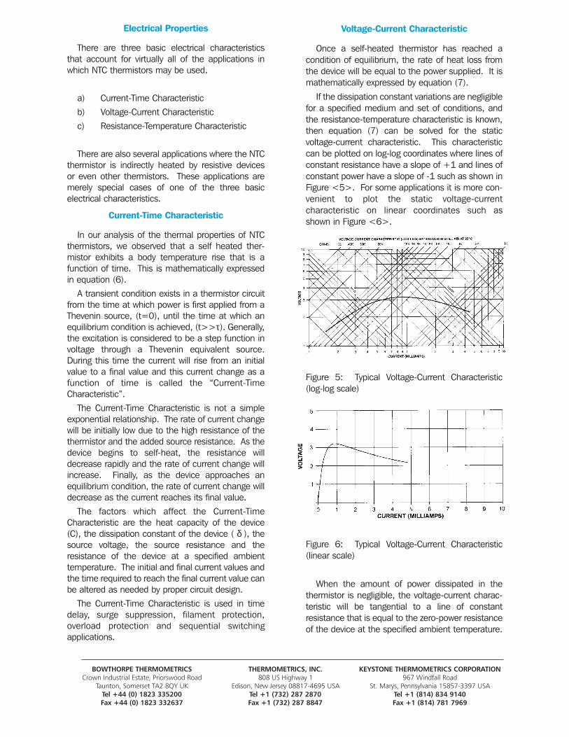
If the dissipation constant variations are negligiblefor a specified medium and set of conditions, andthe resistance-temperature characteristic is known,then equation (7) can be solved for the static voltage-current characteristic. This characteristiccan be plotted on log-log coordinates where lines ofconstant resistance have a slope of +1 and lines ofconstant power have a slope of -1 such as shown inFigure <5>. For some applications it is more con-venient to plot the static voltage-current characteristic on linear coordinates such as shown in Figure <6>.
Figure 5: Typical Voltage-Current Characteristic (log-log scale)
Figure 6: Typical Voltage-Current Characteristic (linear scale)
When the amount of power dissipated in the thermistor is negligible, the voltage-current charac-teristic will be tangential to a line of constant resistance that is equal to the zero-power resistanceof the device at the specified ambient temperature.
BOWTHORPE THERMOMETRICS THERMOMETRICS, INC. KEYSTONE THERMOMETRICS CORPORATIONCrown Industrial Estate, Priorswood Road 808 US Highway 1 967 Windfall Road
Taunton, Somerset TA2 8QY UK Edison, New Jersey 08817-4695 USA St. Marys, Pennsylvania 15857-3397 USATel +44 (0) 1823 335200 Tel +1 (732) 287 2870 Tel +1 (814) 834 9140Fax +44 (0) 1823 332637 Fax +1 (732) 287 8847 Fax +1 (814) 781 7969
As the current continues to be increased, theeffects of self-heating become more evident and thetemperature of the thermistor rises with a resultantdecrease in its resistance. For each subsequentincremental increase in current there is a corresponding decrease in resistance. Hence, theslope of the voltage-current characteristic ( ∆E/∆I )decreases with increasing current. This continuesuntil a current value ( IP ) is reached for which theslope becomes zero and the voltage reaches a maximum value ( EP ). As the current is increasedabove the value of ( I P ), the slope of the character-istic continues to decrease and the thermistorexhibits a negative resistance characteristic.
A maximum power rating as well as power derating curve is usually given for each thermistortype. Care should be exercised when designing acircuit for a self heated application so that the thermistor is operated within the maximum power limitations.
There are many applications which are basedupon the static voltage-current characteristic. Theseapplications can be grouped according to the type of excitation which is employed to vary the voltage-current characteristic.
The first major group involves applications wherethe dissipation constant is varied. This can beaccomplished by changing the thermal conductivityof the medium, the relative motion of the medium orthe heat transfer from the thermistor to its surroundings. Typical applications would includevacuum manometers, anemometers, flow meters,liquid level, fluid velocity, thermal conductivity cells,gas chromatography and gas analysis.
The second major group involves applicationswhere the electrical parameters of the circuit arevaried. This would involve a change in the Theveninsource voltage or source resistance. Typical applications would include automatic gain or amplitude control, voltage regulation, equalization,volume limiters, signal compression or expansionand switching devices.
The third and fourth major groups involve applications where the ambient temperature is varied. In one case the change is thermal, while inthe other case the change is due to radiationabsorbed by the thermistor. Temperature controland alarm indication are examples of applicationswhere the change is thermal. Microwave powermeasurement is an example of an application wherethe change is due to absorbed radiation.
Resistance-Temperature Characteristic
There are many applications based upon theresistance-temperature characteristic and they canbe grouped into the general categories of resistancethermometry, temperature control or temperaturecompensation. In the previous discussions of thecurrent-time and voltage-current characteristics, weexamined devices that were operated in a self-heated mode (heated above the ambient temperature by the power being dissipated in thethermistor). For most applications based on the R-T characteristic the self-heating effect is undesir-able and one attempts to work with as close to zero-power as possible.
The zero-power resistance of a thermistor ( RT ) ata specified temperature ( T ) is the DC resistancemeasured when the power dissipation is negligible.By definition in MIL-PRF-23648, the power is considered to be negligible when “any furtherdecrease in power will result in not more than 0.1percent (or 1/10 of the specified measurement tolerance, whichever is smaller) change in resistance”.
There are two models presently used to explainthe electrical conduction mechanism for NTC thermistors. One explanation involves the so called“hopping” model and the other explanation is basedupon the “energy band” model. Both conductionmodels have difficulty when it comes to a completeexplanation of the R-T characteristics of metal oxidethermistors. Fortunately, there are a number ofequations that can be used to define the resistance-temperature characteristic of the devices.
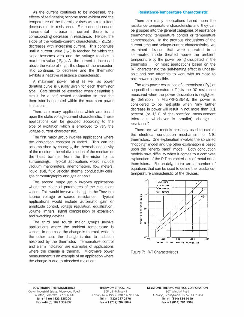
Figure 7: R-T Characteristics
BOWTHORPE THERMOMETRICS THERMOMETRICS, INC. KEYSTONE THERMOMETRICS CORPORATIONCrown Industrial Estate, Priorswood Road 808 US Highway 1 967 Windfall Road
Taunton, Somerset TA2 8QY UK Edison, New Jersey 08817-4695 USA St. Marys, Pennsylvania 15857-3397 USATel +44 (0) 1823 335200 Tel +1 (732) 287 2870 Tel +1 (814) 834 9140Fax +44 (0) 1823 332637 Fax +1 (732) 287 8847 Fax +1 (814) 781 7969
The R-T characteristic of semiconductors is very often plotted with the logarithm of specific resistance expressed as a function of the reciprocalof absolute temperature. In Figure <7>, the R-Tcharacteristics of three commonly used thermistormaterials are shown in terms of their specified resis-tances and inverse absolute temperatures. Theresistance-ratio versus temperature characteristicsfor these materials are specified in MIL-PRF-23648.
It can be demonstrated that, over any specifiedtemperature range for which the slope of a givenmaterial system curve may be considered to be constant (straight line relationship between In RTand 1/T), the resistance of the device at any tem-perature within the specified range may beexpressed as:
β (TO-T)TTO (10)
where: ( RT ) is the resistance at an absolute temperature (T) expressed in kelvins (°C + 273.15); (β) is the “beta” or “material constant” is the slope of the thermistor R-T charac-teristic (in kelvins) over the specified temperaturerange; and, RT0 is the resistance at a specified reference temperature, T0, that is also expressed in kelvins.
Equations (10) appears most frequently in NTCthermistor literature. Thermistor manufacturers willprovide “beta” information for each of the materialsystems they offer. Temperature spans of 0 to 50°C, 25 to 85°C, 25 to 125°C and 100 to 200°Fare most common, however, any two data pointscan be used for solution. The terms equation (10)can be rearranged to solve for beta or temperature:
TTO RT
TO-T RTO (11)
1 RT 1 β RTO TO (12)
Also, the temperature coefficient of resistance or “alpha” ( α ) of an NTC thermistor is defined as:
1 d RT
RT dT (13)
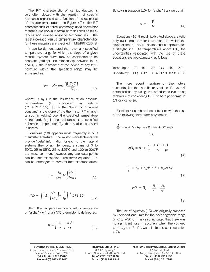
By solving equation (10) for “alpha” ( α ) we obtain:
βT2 (14)
Equations (10) through (14) cited above are validonly over small temperature spans for which theslope of the InRT vs 1/T characteristic approximatesa straight line. At temperatures above 0°C, theuncertainties associated with the use of these equations are approximately as follows:
Temp. span (°C) 10 20 30 40 50
Uncertainty (°C) 0.01 0.04 0.10 0.20 0.30
The more recent literature on thermistorsaccounts for the non-linearity of In RT vs 1/T characteristic by using the standard curve fittingtechnique of considering In RT to be a polynomial in1/T or vice versa.
Excellent results have been obtained with the useof the following third order polynomials:
1T
(15)
B + C + D
T T2 T3
(16)
1 T
(17)
B1 + B3
T T3
(18)
The use of equation (15) was originally proposedby Steinhart and Hart for the oceanographic rangeof -2 to +30°C. They also indicated that there wasno significant loss in accuracy when the squaredterm, a2 { In RT }2 , was eliminated as in equation(17).
BOWTHORPE THERMOMETRICS THERMOMETRICS, INC. KEYSTONE THERMOMETRICS CORPORATIONCrown Industrial Estate, Priorswood Road 808 US Highway 1 967 Windfall Road
Taunton, Somerset TA2 8QY UK Edison, New Jersey 08817-4695 USA St. Marys, Pennsylvania 15857-3397 USATel +44 (0) 1823 335200 Tel +1 (732) 287 2870 Tel +1 (814) 834 9140Fax +44 (0) 1823 332637 Fax +1 (732) 287 8847 Fax +1 (814) 781 7969
1n
1n
RT = RTO exp [ [[ [
[ [ [[
[ [
β =
t(°C) = -273.15
α =
α = –
lnRT = A0 +
lnRT = B0 +-1
= a + b[lnRT] + c[lnRT]2 + d[lnRT]3
= b0 + b1[lnRT]2 + b3[lnRT]3
+
The work of Steinhart and Hart was confirmed bystudies conducted by B.W. Mangum at NBS and R.Koehler at Woods Hole Oceanographic Institute.However, they found that greater accuracy is obtained when the squared term is retained.
The results of the investigations conducted atThermometrics, Inc. indicate excellent curve fit usingthird degree polynomials and are summarized in theTable <1>.
Because equations (15) and (16) each have fourunknown constants, a minimum of four calibrationdata points are required in order to determine theconstants. The constants may be obtained from thesolution of four simultaneous equations if only fourdata points are given, or, they may be obtained bypolynomial regression analysis when more than fourpoints are given. Such an analysis statisticallyimproves the accuracy of the data.
Table 1: Summary of curve fitting errors
A) Full third degree polynomials, such as equa-tions (15) and (16), do not introduce interpo-lation errors that exceed the total measure-ment uncertainty (typically 0.005°C to 0.010°C) for:
a1) 100°C spans within the overall range of -80 to +260°C.
a2) 150°C spans within the overall range of -60 to +260°C.
a3) 150 to 200°C spans within the overall rangeof 0 to +260°C except that the interpolationerror begins to approximate the measurementuncertainties.
B) Third degree polynomials with the squaredterm eliminated, such as equations (17) and(18), introduce interpolation errors that donot exceed the following conditions:
b1) .001 to .003°C error for 50 °C spans within the overall range of 0°C to +260°C.
b2) .010 to .020°C error for 50°C spans within the overall range of -80 to 0°C.
b3) .010°C error for 100°C spans within the over-all range of 0 to +260°C.
b4) .020 to .030°C error for 100°C spans withinthe overall range of -80 to +25°C.
b5) .015°C error for 150°C span (+50 to+200°C).
b6) .045°C error for 150°C span (0 to +150°C).
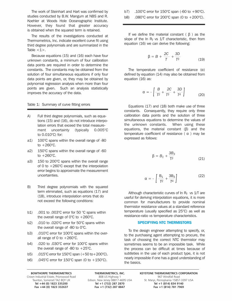
b7) .100°C error for 150°C span (-60 to +90°C).b8) .080°C error for 200°C span (0 to +200°C).
If we define the material constant ( β ) as theslope of the In RT vs 1/T characteristic, then fromequation (16) we can derive the following:
2C 3DT T3 (19)
The temperature coefficient of resistance (α)defined by equation (14) may also be obtained fromequation (16) as:
B 2C 3D T2 T3 T4 (20)
Equations (17) and (18) both make use of threeconstants. Consequently, they require only threecalibration data points and the solution of threesimultaneous equations to determine the values ofthe unknown constants. When using these equations, the material constant (β) and the temperature coefficient of resistance ( α ) may beexpressed as follows:
3B3
T3 (21)
B1 3B3 (22)T2 T4
Although characteristic curves of In RT vs 1/T areuseful for deriving interpolation equations, it is morecommon for manufacturers to provide nominal thermistor resistance values at a standard referencetemperature (usually specified as 25°C) as well asresistance-ratio vs temperature characteristics.
SPECIFYING NTC THERMISTORS
To the design engineer attempting to specify, or,to the purchasing agent attempting to procure, thetask of choosing the correct NTC thermistor maysometimes seems to be an impossible task. Whilethe process can be difficult at times because of subtleties in the use of each product type, it is notnearly impossible if one has a good understanding ofthe basics.
BOWTHORPE THERMOMETRICS THERMOMETRICS, INC. KEYSTONE THERMOMETRICS CORPORATIONCrown Industrial Estate, Priorswood Road 808 US Highway 1 967 Windfall Road
Taunton, Somerset TA2 8QY UK Edison, New Jersey 08817-4695 USA St. Marys, Pennsylvania 15857-3397 USATel +44 (0) 1823 335200 Tel +1 (732) 287 2870 Tel +1 (814) 834 9140Fax +44 (0) 1823 332637 Fax +1 (732) 287 8847 Fax +1 (814) 781 7969
[ [
β = B +
α = - +
+
+
β = B1 +
[ [
α = - +
Product Type and Size:Usually, the designer or user will have a good idea
as to the device size, thermal response time or otherphysical characteristic that they desire in the thermistor. Even if there is only limited informationavailable, it is usually enough to “rule out” whole families of NTC product types because they will betoo far from the desired characteristics. A carefulconsideration of what the thermistor is intended todo in the application will also provide clues as towhich products are inappropriate.
Resistance-Temperature Curves:Most NTC thermistor manufacturers provide
tables of either resistance or resistance-ratio versustemperature for each of the material systems thatthey offer in their respective product lines. Often themanufacturer will also provide the coefficients forthe various thermistor equations in order to assistthe designer or user to interpolate the R-T data.There are a great many material systems in use andeach one has certain limitations with respect to thetype of thermistor that can be manufactured, thesize of the thermistor, temperature ranges for oper-ation and storage, as well as the range of available nominal resistance values.
Nominal Resistance Value:The next common starting point when specifying
a thermistor is to choose the nominal resistance at a specified temperature. As previously mentioned, manufacturers will present a range ofavailable resistance values for each NTC producttype and its associated material systems. The usualreference temperature is 25°C, however, many otherreference temperatures can be specified. If thedesired resistance value is not available for thatcombination of product type and material system,then the user must determined which is more impor-tant: the product type and size, or, the material system with its defined resistance-ratio versus temperature data. The user can not specifyall three parameters (nominal resistance, producttype/size, material system) if the combination fallsoutside of the manufacturers guidelines.
Resistance Tolerance:
The standard tolerances available for each thermistor type are given on the specific productdata sheet. Typically, the bead type thermistors willhave a distribution (3 sigma) of the zero-powerresistance at the reference temperature of about ± 20% to ± 25% depending upon sizes. The metallized surface contact type thermistors havetypical resistance distributions of about ± 5% to ± 10%, except for flake type thermistors where distribution may be ± 20% or greater. Specifyingthe broadest possible tolerance for the applicationwill provide the most cost effective solution. Ofcourse, tighter zero-power resistance tolerances are available for all types of thermistors, however, thelower expected yield from the production lots willtranslate into higher cost. In this regard, the metallized surface contact type thermistors have anadvantage since their shapes can easily be adjustedor trimmed to provide closer tolerances at lower costs.
Beta Tolerance:
The beta of a thermistor is determined by thecomposition and structure of the various metaloxides being used in the device. The beta can alsobe influenced by some manufacturing process variables. The result will be a variation from unit tounit within a production lot as well as from lot to lot.
For bead type thermistors, beta tolerances areusually on the order of ± 1% to ± 3% (up to ±5% is possible for some material systems). For themetallized surface contact type thermistors, betatolerances will range from ±0.5% up to ± 3%.
Resistance Limits:
The maximum and minimum resistance values atthe reference temperature are fixed by the specifiedtolerance. As the temperature is changed from thereference temperature, however, the maximum andminimum limits (as percentage of the nominal resistance) will increase due to the effects of the tolerance on the material constant, beta (β).
If the temperature span is small enough so thatthe beta can be considered constant, then equation(10) can be used to solve for the minimum andmaximum resistance values. The equation is solvedfor all the possible combinations of high and low resistance as well as high and low beta. A typi-cal plot of the resulting R-T data is shown in figure <8>.
BOWTHORPE THERMOMETRICS THERMOMETRICS, INC. KEYSTONE THERMOMETRICS CORPORATIONCrown Industrial Estate, Priorswood Road 808 US Highway 1 967 Windfall Road
Taunton, Somerset TA2 8QY UK Edison, New Jersey 08817-4695 USA St. Marys, Pennsylvania 15857-3397 USATel +44 (0) 1823 335200 Tel +1 (732) 287 2870 Tel +1 (814) 834 9140Fax +44 (0) 1823 332637 Fax +1 (732) 287 8847 Fax +1 (814) 781 7969
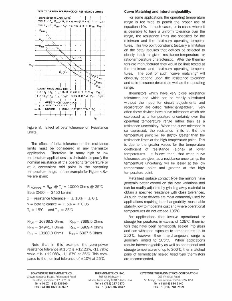
Figure 8: Effect of beta tolerance on ResistanceLimits.
The effect of beta tolerance on the resistance limits must be considered in any thermistor application. Therefore, in many high or low temperature applications it is desirable to specify thenominal resistance at the operating temperature orat a convenient mid point in the operating temperature range. In the example for Figure <8>we are given:
R NOMINAL = RTO @ T0 = 10000 Ohms @ 25°C
Beta (0/50) = 3450 kelvins
x = resistance tolerance = ± 10% = ± 0.1
y = beta tolerance = ± 5% = ± 0.05
TL = 15°C and TH = 35°C
RTLH = 16769.3 Ohms RTHH= 7699.5 Ohms
RTLN = 14941.7 Ohms RTHN= 6869.4 Ohms
RTLL = 13180.3 Ohms RTHL= 6067.5 Ohms
Note that in this example the zero-power resistance tolerance at 15°C is +12.23%, -11.79%;while it is +12.08%, -11.67% at 35°C. This com-pares to the nominal tolerance of ±10% at 25°C.
Curve Matching and Interchangeability:
For some applications the operating temperaturerange is too wide to permit the proper use of equation (10). In such cases, or in cases where itis desirable to have a uniform tolerance over therange, the resistance limits are specified for the minimum and the maximum operating tempera-tures. This two point constraint (actually a limitationon the beta) requires that devices be selected toclosely track a given resistance-temperature or ratio-temperature characteristic. After the thermis-tors are manufactured they would be limit tested atthe minimum and maximum operating tempera-tures. The cost of such “curve matching” will obviously depend upon the resistance tolerance and ratio tolerance desired as well as the operatingrange.
Thermistors which have very close resistancetolerances and which can be readily substitutedwithout the need for circuit adjustments and recalibration are called “Interchangeables”. Veryoften these devices have curve tolerances which areexpressed as a temperature uncertainty over theoperating temperature range rather than as a resistance uncertainty. When the curve tolerance isso expressed, the resistance limits at the low temperature point will be slightly greater than theresistance limits at the high temperature point. Thisis due to the greater values for the temperaturecoefficient of resistance (alpha) at lower temperatures. It follows then, that when curve tolerances are given as a resistance uncertainty, thetemperature uncertainty will be lesser at the lowtemperature point and greater at the high temperature point.
Metallized surface contact type thermistors havegenerally better control on the beta variations andcan be readily adjusted by grinding away material toobtain a specified resistance with close tolerances.As such, these devices are most commonly used forapplications requiring interchangeability, reasonablestability, low to moderate cost and where operationaltemperatures do not exceed 105°C.
For applications that involve operational or storage temperatures in excess of 105°C, thermis-tors that have been hermetically sealed into glassand can withstand exposure to temperatures up to250°C, however, their interchangeable range is generally limited to 105°C. When applicationsrequire interchangeability as well as operational andstorage temperatures of up to 300°C, then matchedpairs of hermetically sealed bead type thermistorsare recommended.
BOWTHORPE THERMOMETRICS THERMOMETRICS, INC. KEYSTONE THERMOMETRICS CORPORATIONCrown Industrial Estate, Priorswood Road 808 US Highway 1 967 Windfall Road
Taunton, Somerset TA2 8QY UK Edison, New Jersey 08817-4695 USA St. Marys, Pennsylvania 15857-3397 USATel +44 (0) 1823 335200 Tel +1 (732) 287 2870 Tel +1 (814) 834 9140Fax +44 (0) 1823 332637 Fax +1 (732) 287 8847 Fax +1 (814) 781 7969
The beta and resistance tolerances for bead typethermistors are generally too broad to permit effec-tive and economic use of a single thermistor in suchhigh temperature, interchangeable applications —-unless the temperature span is very small. Theusual approach to a solution involves the calibrationof the bead type thermistors at two or more tem-perature points over the operating range. The datais entered into computer files for sorting and analysis. The beads are then matched such thathigh and low beta values offset each other. Thus,when the beads are connected in either a series orparallel pair, they will behave as a single interchangeable device and track a defined resis-tance-temperature characteristic.
Such matching of bead type thermistors, (beads,probes or rods) is more costly than precision grinding of metallized surface contact type thermis-tors. However, it may be the only acceptable solution for applications where small sizes, continu-ous operation at high temperatures or high reliabilityare required.
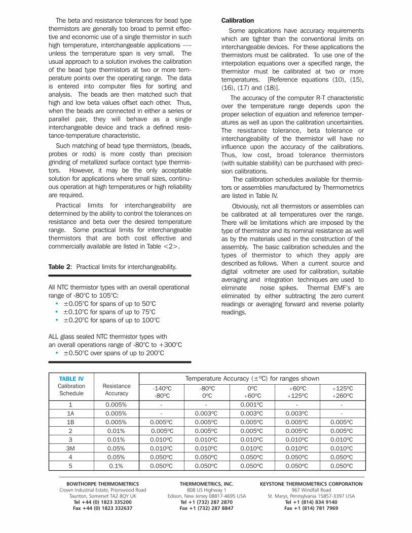
Practical limits for interchangeability are determined by the ability to control the tolerances onresistance and beta over the desired temperaturerange. Some practical limits for interchangeablethermistors that are both cost effective and commercially available are listed in Table <2>.
Table 2: Practical limits for interchangeability.
All NTC thermistor types with an overall operational range of -80°C to 105°C:
• ±0.05°C for spans of up to 50°C• ±0.10°C for spans of up to 75°C• ±0.20°C for spans of up to 100°C
ALL glass sealed NTC thermistor types with an overall operations range of -80°C to +300°C
• ±0.50°C over spans of up to 200°C
CalibrationSome applications have accuracy requirements
which are tighter than the conventional limits oninterchangeable devices. For these applications thethermistors must be calibrated. To use one of theinterpolation equations over a specified range, thethermistor must be calibrated at two or more temperatures. [Reference equations (10), (15),(16), (17) and (18)].
The accuracy of the computer R-T characteristicover the temperature range depends upon theproper selection of equation and reference temper-atures as well as upon the calibration uncertainties.The resistance tolerance, beta tolerance or interchangeability of the thermistor will have noinfluence upon the accuracy of the calibrations.Thus, low cost, broad tolerance thermistors (with suitable stability) can be purchased with preci-sion calibrations.
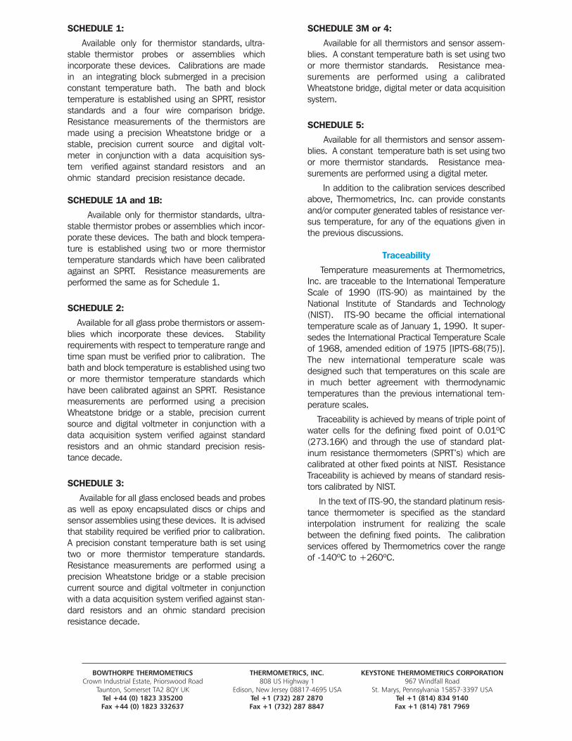
The calibration schedules available for thermis-tors or assemblies manufactured by Thermometricsare listed in Table IV.
Obviously, not all thermistors or assemblies canbe calibrated at all temperatures over the range.There will be limitations which are imposed by thetype of thermistor and its nominal resistance as wellas by the materials used in the construction of theassembly. The basic calibration schedules and thetypes of thermistor to which they apply aredescribed as follows. When a current source anddigital voltmeter are used for calibration, suitableaveraging and integration techniques are used toeliminate noise spikes. Thermal EMF’s are eliminated by either subtracting the zero currentreadings or averaging forward and reverse polarityreadings.
BOWTHORPE THERMOMETRICS THERMOMETRICS, INC. KEYSTONE THERMOMETRICS CORPORATIONCrown Industrial Estate, Priorswood Road 808 US Highway 1 967 Windfall Road
Taunton, Somerset TA2 8QY UK Edison, New Jersey 08817-4695 USA St. Marys, Pennsylvania 15857-3397 USATel +44 (0) 1823 335200 Tel +1 (732) 287 2870 Tel +1 (814) 834 9140Fax +44 (0) 1823 332637 Fax +1 (732) 287 8847 Fax +1 (814) 781 7969
TABLE IVCalibrationSchedule
ResistanceAccuracy
-140ºC-80ºC
-80ºC0ºC
0ºC+60ºC
+60ºC+125ºC
+125ºC+260ºC
Temperature Accuracy (±ºC) for ranges shown
1 0.005% - - 0.001ºC - -1A 0.005% - 0.003ºC 0.003ºC 0.003ºC -1B 0.005% 0.005ºC 0.005ºC 0.005ºC 0.005ºC 0.005ºC2 0.01% 0.005ºC 0.005ºC 0.005ºC 0.005ºC 0.005ºC3 0.01% 0.010ºC 0.010ºC 0.010ºC 0.010ºC 0.010ºC
3M 0.05% 0.010ºC 0.010ºC 0.010ºC 0.010ºC 0.010ºC4 0.05% 0.050ºC 0.050ºC 0.050ºC 0.050ºC 0.050ºC5 0.1% 0.050ºC 0.050ºC 0.050ºC 0.050ºC 0.050ºC
BOWTHORPE THERMOMETRICS THERMOMETRICS, INC. KEYSTONE THERMOMETRICS CORPORATIONCrown Industrial Estate, Priorswood Road 808 US Highway 1 967 Windfall Road
Taunton, Somerset TA2 8QY UK Edison, New Jersey 08817-4695 USA St. Marys, Pennsylvania 15857-3397 USATel +44 (0) 1823 335200 Tel +1 (732) 287 2870 Tel +1 (814) 834 9140Fax +44 (0) 1823 332637 Fax +1 (732) 287 8847 Fax +1 (814) 781 7969
SCHEDULE 3M or 4:
Available for all thermistors and sensor assem-blies. A constant temperature bath is set using twoor more thermistor standards. Resistance mea-surements are performed using a calibratedWheatstone bridge, digital meter or data acquisitionsystem.
SCHEDULE 5:
Available for all thermistors and sensor assem-blies. A constant temperature bath is set using twoor more thermistor standards. Resistance mea-surements are performed using a digital meter.
In addition to the calibration services describedabove, Thermometrics, Inc. can provide constantsand/or computer generated tables of resistance ver-sus temperature, for any of the equations given inthe previous discussions.
Traceability
Temperature measurements at Thermometrics,Inc. are traceable to the International TemperatureScale of 1990 (ITS-90) as maintained by theNational Institute of Standards and Technology(NIST). ITS-90 became the official internationaltemperature scale as of January 1, 1990. It super-sedes the International Practical Temperature Scaleof 1968, amended edition of 1975 [IPTS-68(75)].The new international temperature scale wasdesigned such that temperatures on this scale arein much better agreement with thermodynamictemperatures than the previous international tem-perature scales.
Traceability is achieved by means of triple point ofwater cells for the defining fixed point of 0.01ºC(273.16K) and through the use of standard plat-inum resistance thermometers (SPRT’s) which arecalibrated at other fixed points at NIST. ResistanceTraceability is achieved by means of standard resis-tors calibrated by NIST.
In the text of ITS-90, the standard platinum resis-tance thermometer is specified as the standardinterpolation instrument for realizing the scalebetween the defining fixed points. The calibrationservices offered by Thermometrics cover the rangeof -140ºC to +260ºC.
SCHEDULE 1:
Available only for thermistor standards, ultra-stable thermistor probes or assemblies whichincorporate these devices. Calibrations are madein an integrating block submerged in a precisionconstant temperature bath. The bath and blocktemperature is established using an SPRT, resistorstandards and a four wire comparison bridge.Resistance measurements of the thermistors aremade using a precision Wheatstone bridge or astable, precision current source and digital volt-meter in conjunction with a data acquisition sys-tem verified against standard resistors and anohmic standard precision resistance decade.
SCHEDULE 1A and 1B:
Available only for thermistor standards, ultra-stable thermistor probes or assemblies which incor-porate these devices. The bath and block tempera-ture is established using two or more thermistortemperature standards which have been calibratedagainst an SPRT. Resistance measurements areperformed the same as for Schedule 1.
SCHEDULE 2:
Available for all glass probe thermistors or assem-blies which incorporate these devices. Stabilityrequirements with respect to temperature range andtime span must be verified prior to calibration. Thebath and block temperature is established using twoor more thermistor temperature standards whichhave been calibrated against an SPRT. Resistancemeasurements are performed using a precisionWheatstone bridge or a stable, precision currentsource and digital voltmeter in conjunction with adata acquisition system verified against standardresistors and an ohmic standard precision resis-tance decade.
SCHEDULE 3:
Available for all glass enclosed beads and probesas well as epoxy encapsulated discs or chips andsensor assemblies using these devices. It is advisedthat stability required be verified prior to calibration.A precision constant temperature bath is set usingtwo or more thermistor temperature standards.Resistance measurements are performed using aprecision Wheatstone bridge or a stable precisioncurrent source and digital voltmeter in conjunctionwith a data acquisition system verified against stan-dard resistors and an ohmic standard precisionresistance decade.
BOWTHORPE THERMOMETRICS THERMOMETRICS, INC. KEYSTONE THERMOMETRICS CORPORATIONCrown Industrial Estate, Priorswood Road 808 US Highway 1 967 Windfall Road
Taunton, Somerset TA2 8QY UK Edison, New Jersey 08817-4695 USA St. Marys, Pennsylvania 15857-3397 USATel +44 (0) 1823 335200 Tel +1 (732) 287 2870 Tel +1 (814) 834 9140Fax +44 (0) 1823 332637 Fax +1 (732) 287 8847 Fax +1 (814) 781 7969
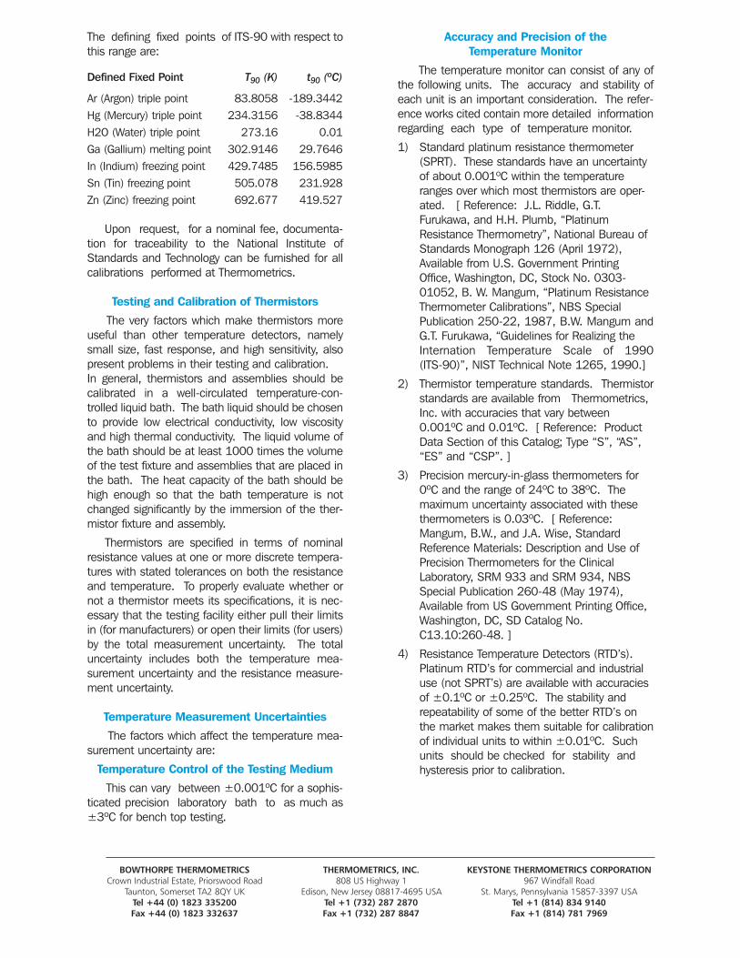
The defining fixed points of ITS-90 with respect tothis range are:
Defined Fixed Point T90 (K) t90 (ºC)
Ar (Argon) triple point 83.8058 -189.3442Hg (Mercury) triple point 234.3156 -38.8344H2O (Water) triple point 273.16 0.01Ga (Gallium) melting point 302.9146 29.7646In (Indium) freezing point 429.7485 156.5985Sn (Tin) freezing point 505.078 231.928Zn (Zinc) freezing point 692.677 419.527
Upon request, for a nominal fee, documenta-tion for traceability to the National Institute ofStandards and Technology can be furnished for allcalibrations performed at Thermometrics.
Testing and Calibration of Thermistors
The very factors which make thermistors moreuseful than other temperature detectors, namelysmall size, fast response, and high sensitivity, alsopresent problems in their testing and calibration.In general, thermistors and assemblies should becalibrated in a well-circulated temperature-con-trolled liquid bath. The bath liquid should be chosento provide low electrical conductivity, low viscosityand high thermal conductivity. The liquid volume ofthe bath should be at least 1000 times the volumeof the test fixture and assemblies that are placed inthe bath. The heat capacity of the bath should behigh enough so that the bath temperature is notchanged significantly by the immersion of the ther-mistor fixture and assembly.
Thermistors are specified in terms of nominalresistance values at one or more discrete tempera-tures with stated tolerances on both the resistanceand temperature. To properly evaluate whether ornot a thermistor meets its specifications, it is nec-essary that the testing facility either pull their limitsin (for manufacturers) or open their limits (for users)by the total measurement uncertainty. The totaluncertainty includes both the temperature mea-surement uncertainty and the resistance measure-ment uncertainty.
Temperature Measurement Uncertainties
The factors which affect the temperature mea-surement uncertainty are:
Temperature Control of the Testing Medium
This can vary between ±0.001ºC for a sophis-ticated precision laboratory bath to as much as±3ºC for bench top testing.
Accuracy and Precision of the Temperature Monitor
The temperature monitor can consist of any ofthe following units. The accuracy and stability ofeach unit is an important consideration. The refer-ence works cited contain more detailed informationregarding each type of temperature monitor.
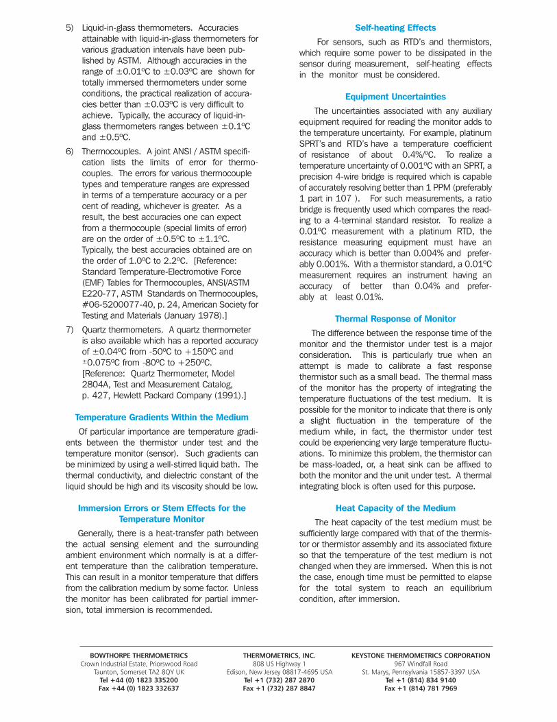
1) Standard platinum resistance thermometer (SPRT). These standards have an uncertainty of about 0.001ºC within the temperature ranges over which most thermistors are oper-ated. [ Reference: J.L. Riddle, G.T. Furukawa, and H.H. Plumb, “Platinum Resistance Thermometry”, National Bureau of Standards Monograph 126 (April 1972), Available from U.S. Government Printing Office, Washington, DC, Stock No. 0303-01052, B. W. Mangum, “Platinum Resistance Thermometer Calibrations”, NBS Special Publication 250-22, 1987, B.W. Mangum andG.T. Furukawa, “Guidelines for Realizing the Internation Temperature Scale of 1990 (ITS-90)”, NIST Technical Note 1265, 1990.]
2) Thermistor temperature standards. Thermistorstandards are available from Thermometrics, Inc. with accuracies that vary between 0.001ºC and 0.01ºC. [ Reference: Product Data Section of this Catalog; Type “S”, “AS”, “ES” and “CSP”. ]
3) Precision mercury-in-glass thermometers for 0ºC and the range of 24ºC to 38ºC. The maximum uncertainty associated with these thermometers is 0.03ºC. [ Reference: Mangum, B.W., and J.A. Wise, Standard Reference Materials: Description and Use of Precision Thermometers for the Clinical Laboratory, SRM 933 and SRM 934, NBS Special Publication 260-48 (May 1974), Available from US Government Printing Office, Washington, DC, SD Catalog No. C13.10:260-48. ]
4) Resistance Temperature Detectors (RTD’s). Platinum RTD’s for commercial and industrial use (not SPRT’s) are available with accuracies of ±0.1ºC or ±0.25ºC. The stability and repeatability of some of the better RTD’s on the market makes them suitable for calibrationof individual units to within ±0.01ºC. Such units should be checked for stability and hysteresis prior to calibration.
BOWTHORPE THERMOMETRICS THERMOMETRICS, INC. KEYSTONE THERMOMETRICS CORPORATIONCrown Industrial Estate, Priorswood Road 808 US Highway 1 967 Windfall Road
Taunton, Somerset TA2 8QY UK Edison, New Jersey 08817-4695 USA St. Marys, Pennsylvania 15857-3397 USATel +44 (0) 1823 335200 Tel +1 (732) 287 2870 Tel +1 (814) 834 9140Fax +44 (0) 1823 332637 Fax +1 (732) 287 8847 Fax +1 (814) 781 7969
5) Liquid-in-glass thermometers. Accuracies attainable with liquid-in-glass thermometers forvarious graduation intervals have been pub-lished by ASTM. Although accuracies in the range of ±0.01ºC to ±0.03ºC are shown for totally immersed thermometers under some conditions, the practical realization of accura-cies better than ±0.03ºC is very difficult to achieve. Typically, the accuracy of liquid-in-glass thermometers ranges between ±0.1ºC and ±0.5ºC.
6) Thermocouples. A joint ANSI / ASTM specifi-cation lists the limits of error for thermo-couples. The errors for various thermocouple types and temperature ranges are expressed in terms of a temperature accuracy or a percent of reading, whichever is greater. As a result, the best accuracies one can expect from a thermocouple (special limits of error) are on the order of ±0.5ºC to ±1.1ºC. Typically, the best accuracies obtained are on the order of 1.0ºC to 2.2ºC. [Reference: Standard Temperature-Electromotive Force (EMF) Tables for Thermocouples, ANSI/ASTM E220-77, ASTM Standards on Thermocouples,#06-5200077-40, p. 24, American Society forTesting and Materials (January 1978).]
7) Quartz thermometers. A quartz thermometer is also available which has a reported accuracyof ±0.04ºC from -50ºC to +150ºC and ±0.075ºC from -80ºC to +250ºC. [Reference: Quartz Thermometer, Model 2804A, Test and Measurement Catalog, p. 427, Hewlett Packard Company (1991).]
Temperature Gradients Within the Medium
Of particular importance are temperature gradi-ents between the thermistor under test and thetemperature monitor (sensor). Such gradients canbe minimized by using a well-stirred liquid bath. Thethermal conductivity, and dielectric constant of theliquid should be high and its viscosity should be low.
Immersion Errors or Stem Effects for theTemperature Monitor
Generally, there is a heat-transfer path betweenthe actual sensing element and the surroundingambient environment which normally is at a differ-ent temperature than the calibration temperature.This can result in a monitor temperature that differsfrom the calibration medium by some factor. Unlessthe monitor has been calibrated for partial immer-sion, total immersion is recommended.
Self-heating Effects
For sensors, such as RTD’s and thermistors,which require some power to be dissipated in thesensor during measurement, self-heating effectsin the monitor must be considered.
Equipment Uncertainties
The uncertainties associated with any auxiliaryequipment required for reading the monitor adds tothe temperature uncertainty. For example, platinumSPRT’s and RTD’s have a temperature coefficientof resistance of about 0.4%/ºC. To realize a temperature uncertainty of 0.001ºC with an SPRT, aprecision 4-wire bridge is required which is capableof accurately resolving better than 1 PPM (preferably1 part in 107 ). For such measurements, a ratiobridge is frequently used which compares the read-ing to a 4-terminal standard resistor. To realize a0.01ºC measurement with a platinum RTD, theresistance measuring equipment must have anaccuracy which is better than 0.004% and prefer-ably 0.001%. With a thermistor standard, a 0.01ºCmeasurement requires an instrument having anaccuracy of better than 0.04% and prefer-ably at least 0.01%.
Thermal Response of Monitor
The difference between the response time of themonitor and the thermistor under test is a majorconsideration. This is particularly true when anattempt is made to calibrate a fast response thermistor such as a small bead. The thermal massof the monitor has the property of integrating thetemperature fluctuations of the test medium. It ispossible for the monitor to indicate that there is onlya slight fluctuation in the temperature of themedium while, in fact, the thermistor under testcould be experiencing very large temperature fluctu-ations. To minimize this problem, the thermistor canbe mass-loaded, or, a heat sink can be affixed toboth the monitor and the unit under test. A thermalintegrating block is often used for this purpose.
Heat Capacity of the Medium
The heat capacity of the test medium must be sufficiently large compared with that of the thermis-tor or thermistor assembly and its associated fixtureso that the temperature of the test medium is notchanged when they are immersed. When this is notthe case, enough time must be permitted to elapsefor the total system to reach an equilibrium condition, after immersion.
BOWTHORPE THERMOMETRICS THERMOMETRICS, INC. KEYSTONE THERMOMETRICS CORPORATIONCrown Industrial Estate, Priorswood Road 808 US Highway 1 967 Windfall Road
Taunton, Somerset TA2 8QY UK Edison, New Jersey 08817-4695 USA St. Marys, Pennsylvania 15857-3397 USATel +44 (0) 1823 335200 Tel +1 (732) 287 2870 Tel +1 (814) 834 9140Fax +44 (0) 1823 332637 Fax +1 (732) 287 8847 Fax +1 (814) 781 7969
Resistance MeasurementUncertainties
The factors which affect the resistance measure-ment uncertainty are:
Resistance Measuring Equipment
The accuracy, precision, stability, and tempera-ture coefficient of the resistance measuringequipment must be considered.
Self-heating Error
The ratio of the power dissipated in the thermis-tor (by the test equipment) to the dissipation constant of the thermistor in the test medium determines the self-heat error.
Stability of the Thermistor Under Test
If a thermistor which has not had sufficient stability conditioning is calibrated at a low tempera-ture and is subse-quently calibrated at an elevatedtemperature, the high temperature exposure maycreate a shift in resistance which gives the appear-ance of a hysteresis effect. This may also occur ifthe thermistor is calibrated at a temperature aboveits maximum rated temperature.
Thermistor and Circuit Lead Resistance
In general, when the desired accuracy of themeasurement requires a resistance resolution thatis less than 1 Ohm, or when the absolute resistanceof the thermistor at a specified temperature will beless than 1000 Ohms, the user must consider thefollowing:
1. The contact resistance between the instrument and its measuring leads.
2. The contact resistance between the instrument leads and the fixture used to hold the thermistor.
3. The temperature coefficient of the instrument and measuring leads.
4. The resistance of the thermistor leads and the ability to make contact on the thermistor leads at exactly the same point each time a measurement is made. This is important when attempting to make measurements on thermis-tors with fine gauge platinum alloy leadwires such as small beads.
Thermal EMF Effects
Thermal EMF’s can result at the instrument ter-minals, the connections between the instrumentleads and the thermistor fixture, the connectionbetween the fixture and the thermistor leads, andelectrical connections between dissimilar metalswithin the fixture itself.
QUALITY ASSURANCEThermometrics maintains a system which com-
plies with MIL-Q-9858. All of our bead and chip thermistors are designed to comply with MIL-PRF-23648. Every Thermometrics thermistorreceives 100% electrical inspection as well as100% visual and mechanical inspection. This is ver-ified by additional QA sampling which varies with theapplication requirements (typically 0.65 AQL or 1.0AQL). Our Applications Engineering Department willgladly provide assistance in selecting the best qual-ification and acceptance testing programs for anyspecific application. We can provide a low costscreening test or sophisticated qualification testingdepending upon your requirements.
APPLICATIONSThe thermistor is a versatile component that can
be used in a wide variety of applications where themeasurand is temperature dependent.
Table I gives a partial listing of thermistor applications which are grouped according to one ofthe three fundamental electrical characteristics:the resistance-temperature characteristic, thevoltage-current characteristic, and the current-time characteristic. The current-time and voltage-current characteristics are associated with self-heated thermistors. The resistance-tempera-ture characteristic is applicable to thermistors operated with negligible self-heat.
Applications which depend on the resistance-temperature characteristic include temperature measurement, control, and compensation. Alsoincluded are those applications for which the temperature of the thermistor is related to someother physical phenomena. An example would bethe use of thermistor type cardiac catheters forthermodilution studies. With this type of device, asaline or dextrose solution, having a known volume and temperature, is injected into theblood stream through one of the catheter lumens.The solution mixes with the blood and is diluted as

BOWTHORPE THERMOMETRICS THERMOMETRICS, INC. KEYSTONE THERMOMETRICS CORPORATIONCrown Industrial Estate, Priorswood Road 808 US Highway 1 967 Windfall Road
Taunton, Somerset TA2 8QY UK Edison, New Jersey 08817-4695 USA St. Marys, Pennsylvania 15857-3397 USATel +44 (0) 1823 335200 Tel +1 (732) 287 2870 Tel +1 (814) 834 9140Fax +44 (0) 1823 332637 Fax +1 (732) 287 8847 Fax +1 (814) 781 7969
it is carried downstream past a thermistor locatedat the surface of another catheter lumen. At thethermistor location, the temperature of the blood-injectate mixture is measured over a period oftime. The cardiac output (efficiency) is computedfrom the temperature-time response data.Another example is an hypsometer, an instrumentin which the temperature of a boiling fluid is usedto determine the pressure to which the fluid isexposed.
Applications based on the voltage-current char-acteristic of a thermistor generally involvechanges in the environmental conditions or circuit variations which, in turn, result in changes in theoperating point on any given curve or family ofcurves.
The current-time characteristic of a thermistordepends on its heat capacity and dissipation constant as well as the circuit in which it is used.Applications which make use of the current-time characteristic include time delay and surgesuppression.
NTC THERMISTOR APPLICATIONS
The NTC thermistor is a versatile component thatcan be used in a wide variety of applications wherethe measured is temperature dependent. Table<3> gives a partial listing of thermistor applicationsthat are grouped according to one of the three fundamental electrical characteristics; the current-time characteristics, the voltage-currentcharacteristic, and the resistance-temperature characteristic.
Applications based on the voltage-current char-acteristic generally involve changes in the environ-mental conditions or the electrical circuit parame-ters of a self-heated thermistor. In turn, thesechanges will result in a shift of the operating pointon any given voltage-current curve or family of suchcurves. These applications are further subdividedinto four major categories depending on the type ofexcitation that causes the operating point tochange.
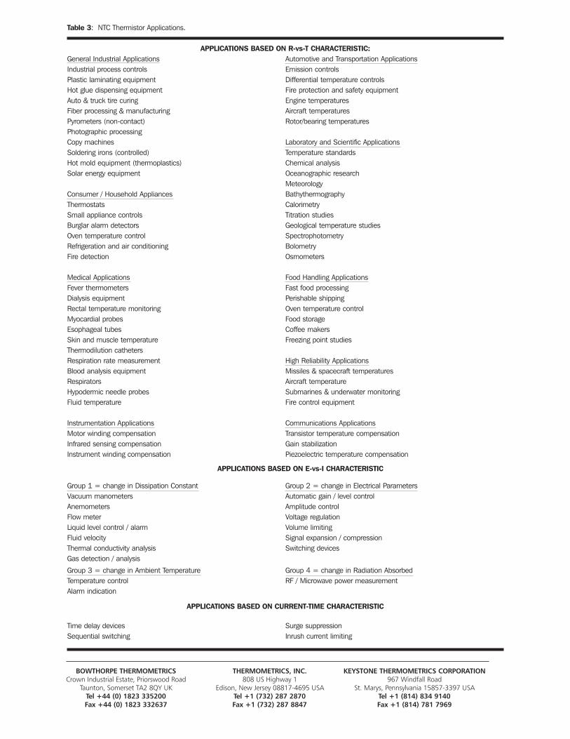
Table 3: NTC Thermistor Applications.
APPLICATIONS BASED ON R-vs-T CHARACTERISTIC:General Industrial Applications Automotive and Transportation ApplicationsIndustrial process controls Emission controlsPlastic laminating equipment Differential temperature controlsHot glue dispensing equipment Fire protection and safety equipmentAuto & truck tire curing Engine temperaturesFiber processing & manufacturing Aircraft temperaturesPyrometers (non-contact) Rotor/bearing temperaturesPhotographic processingCopy machines Laboratory and Scientific ApplicationsSoldering irons (controlled) Temperature standardsHot mold equipment (thermoplastics) Chemical analysisSolar energy equipment Oceanographic research
MeteorologyConsumer / Household Appliances BathythermographyThermostats CalorimetrySmall appliance controls Titration studiesBurglar alarm detectors Geological temperature studiesOven temperature control SpectrophotometryRefrigeration and air conditioning BolometryFire detection Osmometers
Medical Applications Food Handling ApplicationsFever thermometers Fast food processingDialysis equipment Perishable shippingRectal temperature monitoring Oven temperature controlMyocardial probes Food storageEsophageal tubes Coffee makersSkin and muscle temperature Freezing point studiesThermodilution cathetersRespiration rate measurement High Reliability ApplicationsBlood analysis equipment Missiles & spacecraft temperaturesRespirators Aircraft temperatureHypodermic needle probes Submarines & underwater monitoringFluid temperature Fire control equipment
Instrumentation Applications Communications ApplicationsMotor winding compensation Transistor temperature compensationInfrared sensing compensation Gain stabilizationInstrument winding compensation Piezoelectric temperature compensation
APPLICATIONS BASED ON E-vs-I CHARACTERISTIC
Group 1 = change in Dissipation Constant Group 2 = change in Electrical ParametersVacuum manometers Automatic gain / level controlAnemometers Amplitude controlFlow meter Voltage regulationLiquid level control / alarm Volume limitingFluid velocity Signal expansion / compressionThermal conductivity analysis Switching devicesGas detection / analysis
Group 3 = change in Ambient Temperature Group 4 = change in Radiation AbsorbedTemperature control RF / Microwave power measurementAlarm indication
APPLICATIONS BASED ON CURRENT-TIME CHARACTERISTIC
Time delay devices Surge suppressionSequential switching Inrush current limiting
BOWTHORPE THERMOMETRICS THERMOMETRICS, INC. KEYSTONE THERMOMETRICS CORPORATIONCrown Industrial Estate, Priorswood Road 808 US Highway 1 967 Windfall Road
Taunton, Somerset TA2 8QY UK Edison, New Jersey 08817-4695 USA St. Marys, Pennsylvania 15857-3397 USATel +44 (0) 1823 335200 Tel +1 (732) 287 2870 Tel +1 (814) 834 9140Fax +44 (0) 1823 332637 Fax +1 (732) 287 8847 Fax +1 (814) 781 7969
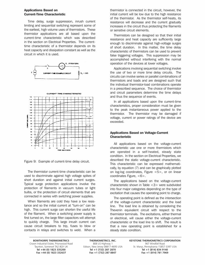
Applications Based on Current-Time Characteristic
Time delay, surge suppression, inrush current limiting and sequential switching represent some ofthe earliest, high volume uses of thermistors. Thesethermistor applications are all based upon the current-time characteristic which was described in the section on Electrical Properties. The current-time characteristic of a thermistor depends on itsheat capacity and dissipation constant as well as the circuit in which it is used.
Figure 9: Example of current-time delay circuit.
The thermistor current-time characteristic can beused to discriminate against high voltage spikes ofshort duration and against initial current surges.Typical surge protection applications involve the protection of filaments in vacuum tubes or lightbulbs, or the protection of circuit elements that areconnected in series with switching power supplies.
When filaments are cold they have a low resis-tance and so the initial current at “turn-on” can behigh. This current surge can shorten the useful lifeof the filament. When a switching power supply isfirst turned on, the large filter capacitors will attemptto quickly charge. This large inrush current cancause circuit breakers to trip, fuses to blow or contacts in relays and switches to weld. When a
thermistor is connected in the circuit, however, theinitial current will be low due to the high resistanceof the thermistor. As the thermistor self-heats, itsresistance will decrease and the current graduallyincreases in the circuit thus protecting the filamentsor sensitive circuit elements.
Thermistors can be designed so that their initialresistance and heat capacity are sufficiently largeenough to discriminate against high-voltage surgesof short duration. In this matter, the time delaycharacteristic of thermistors can be used to preventfalse triggering voltages. This suppression may beaccomplished without interfering with the normaloperation of the devices at lower voltages.
Applications involving sequential switching involvethe use of two or more time delay circuits. The circuits can involve series or parallel combinations ofthermistors and loads and are designed such thatthe individual thermistor-load combinations operatein a prescribed sequence. The choice of thermistorand circuit parameters determine the time delaysand thus the sequence of events.
In all applications based upon the current-timecharacteristics, proper consideration must be givento the peak instantaneous power applied to thethermistor. The thermistor may be damaged if voltage, current or power ratings of the device areexceeded.
Applications Based on Voltage-CurrentCharacteristic
All applications based on the voltage-currentcharacteristic use one or more thermistors whichare operated in a self-heated, steady state condition. In the section on Electrical Properties, wedescribed the static voltage-current characteristic.This characteristic can be expressed mathemati-cally, by equation (7) and can be graphically plottedon log-log coordinates, Figure <5>, or on linear coordinates Figure, <6>.
The applications based on the voltage-currentcharacteristic shown in Table <3> were subdividedinto four major categories depending on the type ofexcitation that causes the operating point to charge.
The operating point is defined as the intersectionof the voltage-current characteristic and the loadline. The load line is obtained by considering theThevenin equivalent circuit with respect to the thermistor terminals. The excitations, either thermalor electrical, will cause either the voltage-currentcharacteristic or the load line to shift. The result isthat a new operating point is established for asteady state condition.
BOWTHORPE THERMOMETRICS THERMOMETRICS, INC. KEYSTONE THERMOMETRICS CORPORATIONCrown Industrial Estate, Priorswood Road 808 US Highway 1 967 Windfall Road
Taunton, Somerset TA2 8QY UK Edison, New Jersey 08817-4695 USA St. Marys, Pennsylvania 15857-3397 USATel +44 (0) 1823 335200 Tel +1 (732) 287 2870 Tel +1 (814) 834 9140Fax +44 (0) 1823 332637 Fax +1 (732) 287 8847 Fax +1 (814) 781 7969
-tº
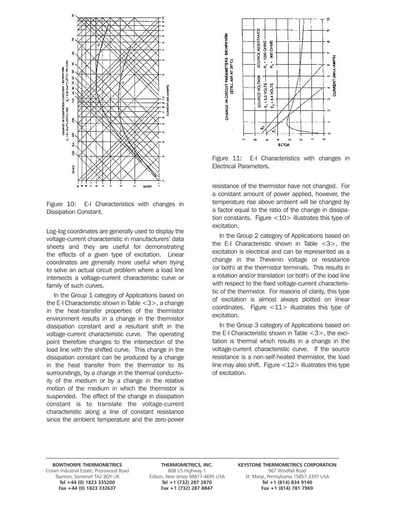
Figure 10: E-I Characteristics with changes inDissipation Constant.
Log-log coordinates are generally used to display thevoltage-current characteristic in manufacturers’ datasheets and they are useful for demonstrating the effects of a given type of excitation. Linear coordinates are generally more useful when trying to solve an actual circuit problem where a load lineintersects a voltage-current characteristic curve orfamily of such curves.
In the Group 1 category of Applications based onthe E-I Characteristic shown in Table <3>, a changein the heat-transfer properties of the thermistor environment results in a change in the thermistordissipation constant and a resultant shift in the voltage-current characteristic curve. The operatingpoint therefore changes to the intersection of theload line with the shifted curve. This change in thedissipation constant can be produced by a change in the heat transfer from the thermistor to its surroundings, by a change in the thermal conductiv-ity of the medium or by a change in the relativemotion of the medium in which the thermistor issuspended. The effect of the change in dissipationconstant is to translate the voltage-current characteristic along a line of constant resistancesince the ambient temperature and the zero-power
Figure 11: E-I Characteristics with changes inElectrical Parameters.
resistance of the thermistor have not changed. Fora constant amount of power applied, however, thetemperature rise above ambient will be changed bya factor equal to the ratio of the change in dissipa-tion constants. Figure <10> illustrates this type ofexcitation.
In the Group 2 category of Applications based onthe E-I Characteristic shown in Table <3>, the excitation is electrical and can be represented as achange in the Thevenin voltage or resistance (or both) at the thermistor terminals. This results ina rotation and/or translation (or both) of the load linewith respect to the fixed voltage-current characteris-tic of the thermistor. For reasons of clarity, this typeof excitation is almost always plotted on linear coordinates. Figure <11> illustrates this type of excitation.
In the Group 3 category of Applications based onthe E-I Characteristic shown in Table <3>, the exci-tation is thermal which results in a change in the voltage-current characteristic curve. If the sourceresistance is a non-self-heated thermistor, the loadline may also shift. Figure <12> illustrates this typeof excitation.
BOWTHORPE THERMOMETRICS THERMOMETRICS, INC. KEYSTONE THERMOMETRICS CORPORATIONCrown Industrial Estate, Priorswood Road 808 US Highway 1 967 Windfall Road
Taunton, Somerset TA2 8QY UK Edison, New Jersey 08817-4695 USA St. Marys, Pennsylvania 15857-3397 USATel +44 (0) 1823 335200 Tel +1 (732) 287 2870 Tel +1 (814) 834 9140Fax +44 (0) 1823 332637 Fax +1 (732) 287 8847 Fax +1 (814) 781 7969
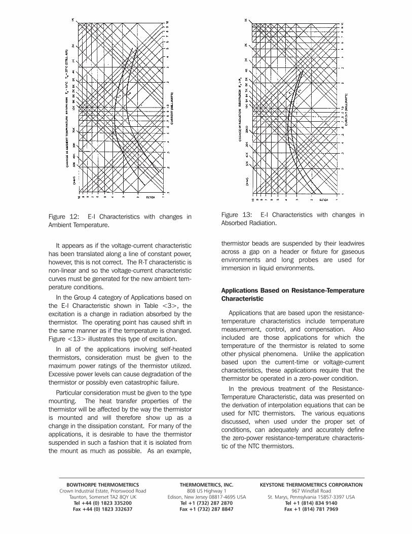
Figure 12: E-I Characteristics with changes inAmbient Temperature.
It appears as if the voltage-current characteristichas been translated along a line of constant power,however, this is not correct. The R-T characteristic isnon-linear and so the voltage-current characteristiccurves must be generated for the new ambient tem-perature conditions.
In the Group 4 category of Applications based onthe E-I Characteristic shown in Table <3>, the excitation is a change in radiation absorbed by thethermistor. The operating point has caused shift inthe same manner as if the temperature is changed.Figure <13> illustrates this type of excitation.
In all of the applications involving self-heatedthermistors, consideration must be given to the maximum power ratings of the thermistor utilized.Excessive power levels can cause degradation of thethermistor or possibly even catastrophic failure.
Particular consideration must be given to the typemounting. The heat transfer properties of the thermistor will be affected by the way the thermistoris mounted and will therefore show up as a change in the dissipation constant. For many of the applications, it is desirable to have the thermistor suspended in such a fashion that it is isolated fromthe mount as much as possible. As an example,
Figure 13: E-I Characteristics with changes inAbsorbed Radiation.
thermistor beads are suspended by their leadwiresacross a gap on a header or fixture for gaseous environments and long probes are used for immersion in liquid environments.
Applications Based on Resistance-TemperatureCharacteristic
Applications that are based upon the resistance-temperature characteristics include temperaturemeasurement, control, and compensation. Alsoincluded are those applications for which the temperature of the thermistor is related to someother physical phenomena. Unlike the applicationbased upon the current-time or voltage-currentcharacteristics, these applications require that thethermistor be operated in a zero-power condition.
In the previous treatment of the Resistance-Temperature Characteristic, data was presented onthe derivation of interpolation equations that can beused for NTC thermistors. The various equationsdiscussed, when used under the proper set of conditions, can adequately and accurately definethe zero-power resistance-temperature characteris-tic of the NTC thermistors.
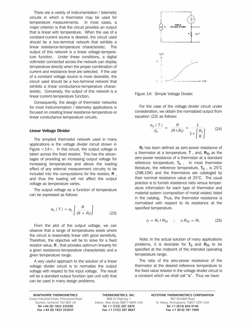
BOWTHORPE THERMOMETRICS THERMOMETRICS, INC. KEYSTONE THERMOMETRICS CORPORATIONCrown Industrial Estate, Priorswood Road 808 US Highway 1 967 Windfall Road
Taunton, Somerset TA2 8QY UK Edison, New Jersey 08817-4695 USA St. Marys, Pennsylvania 15857-3397 USATel +44 (0) 1823 335200 Tel +1 (732) 287 2870 Tel +1 (814) 834 9140Fax +44 (0) 1823 332637 Fax +1 (732) 287 8847 Fax +1 (814) 781 7969
There are a variety of instrumentation / telemetrycircuits in which a thermistor may be used for temperature measurements. In most cases, amajor criterion is that the circuit provides an outputthat is linear with temperature. When the use of aconstant-current source is desired, the circuit usedshould be a two-terminal network that exhibits a linear resistance-temperature characteristic. Theoutput of this network is a linear voltage-tempera-ture function. Under these conditions, a digital voltmeter connected across the network can displaytemperature directly when the proper combination ofcurrent and resistance level are selected. If the useof a constant voltage source is more desirable, thecircuit used should be a two-terminal network thatexhibits a linear conductance-temperature charac-teristic. Conversely, the output of this network is alinear current-temperature function.
Consequently, the design of thermistor networksfor most instrumentation / telemetry applications isfocused on creating linear resistance-temperature orlinear conductance-temperature circuits.
Linear Voltage Divider
The simplest thermistor network used in manyapplications is the voltage divider circuit shown inFigure <14>. In this circuit, the output voltage istaken across the fixed resistor. This has the advan-tages of providing an increasing output voltage forincreasing temperatures and allows the loadingeffect of any external measurement circuitry to beincluded into the computations for the resistor, R ,and thus the loading will not affect the output voltage as temperature varies.
The output voltage as a function of temperaturecan be expressed as follows:
R(R + RT) (23)
From the plot of the output voltage, we canobserve that a range of temperatures exists wherethe circuit is reasonably linear with good sensitivity.Therefore, the objective will be to solve for a fixedresistor value, R , that provides optimum linearity fora given resistance-temperature characteristic and agiven temperature range.
A very useful approach to the solution of a linearvoltage divider circuit is to normalize the output voltage with respect to the input voltage. The resultwill be a standard output function (per unit volt) thatcan be used in many design problems.
Figure 14: Simple Voltage Divider.
For the case of the voltage divider circuit underconsideration, we obtain the normalized output fromequation (23) as follows:
(24)
RT has been defined as zero-power resistance ofa thermistor at a temperature, T , and, RTO as thezero-power resistance of a thermistor at a standardreference temperature, T0 . In most thermistor literature, the reference temperature, TO , is 25°C(298.15K) and the thermistors are cataloged bytheir nominal resistance value at 25°C. The usualpractice is to furnish resistance ratio versus temper-ature information for each type of thermistor andmaterial system (composition of metal oxides) listedin the catalog. Thus, the thermistor resistance isnormalized with respect to its resistance at the specified temperature.
rT = RT I RTO rT RTO = RT (25)
Note: In the actual solution of many applicationsproblems, it is desirable for TO and RTO to be specified at the midpoint of the intended operatingtemperature range.
The ratio of the zero-power resistance of the thermistor at the desired reference temperature tothe fixed value resistor in the voltage divider circuit isa constant which we shall call “s”. Thus we have:
[ [
[ [eo ( T ) = es
eo ( T ) R 1es (R+RT) 1+
= =RT
R
...
-tº
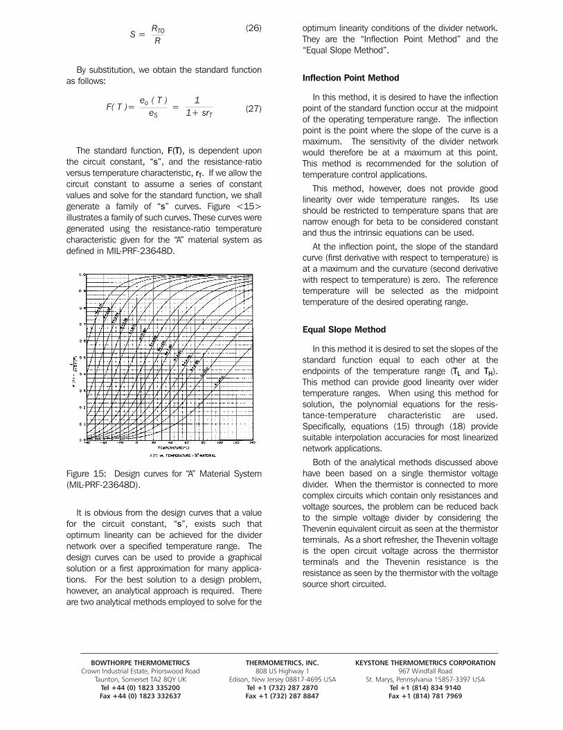
BOWTHORPE THERMOMETRICS THERMOMETRICS, INC. KEYSTONE THERMOMETRICS CORPORATIONCrown Industrial Estate, Priorswood Road 808 US Highway 1 967 Windfall Road
Taunton, Somerset TA2 8QY UK Edison, New Jersey 08817-4695 USA St. Marys, Pennsylvania 15857-3397 USATel +44 (0) 1823 335200 Tel +1 (732) 287 2870 Tel +1 (814) 834 9140Fax +44 (0) 1823 332637 Fax +1 (732) 287 8847 Fax +1 (814) 781 7969
(26)
By substitution, we obtain the standard functionas follows:
(27)
The standard function, F(T), is dependent uponthe circuit constant, “s”, and the resistance-ratio versus temperature characteristic, rT. If we allow thecircuit constant to assume a series of constant values and solve for the standard function, we shallgenerate a family of “s” curves. Figure <15> illustrates a family of such curves. These curves weregenerated using the resistance-ratio temperaturecharacteristic given for the “A” material system asdefined in MIL-PRF-23648D.
Figure 15: Design curves for “A” Material System(MIL-PRF-23648D).
It is obvious from the design curves that a valuefor the circuit constant, “s”, exists such that optimum linearity can be achieved for the dividernetwork over a specified temperature range. Thedesign curves can be used to provide a graphicalsolution or a first approximation for many applica-tions. For the best solution to a design problem,however, an analytical approach is required. Thereare two analytical methods employed to solve for the
optimum linearity conditions of the divider network.They are the “Inflection Point Method” and the“Equal Slope Method”.
Inflection Point Method
In this method, it is desired to have the inflectionpoint of the standard function occur at the midpointof the operating temperature range. The inflectionpoint is the point where the slope of the curve is amaximum. The sensitivity of the divider networkwould therefore be at a maximum at this point. This method is recommended for the solution of temperature control applications.
This method, however, does not provide good linearity over wide temperature ranges. Its useshould be restricted to temperature spans that arenarrow enough for beta to be considered constantand thus the intrinsic equations can be used.
At the inflection point, the slope of the standardcurve (first derivative with respect to temperature) isat a maximum and the curvature (second derivativewith respect to temperature) is zero. The referencetemperature will be selected as the midpoint temperature of the desired operating range.
Equal Slope Method
In this method it is desired to set the slopes of thestandard function equal to each other at the endpoints of the temperature range (TL and TH).This method can provide good linearity over widertemperature ranges. When using this method forsolution, the polynomial equations for the resis-tance-temperature characteristic are used.Specifically, equations (15) through (18) providesuitable interpolation accuracies for most linearizednetwork applications.
Both of the analytical methods discussed abovehave been based on a single thermistor voltagedivider. When the thermistor is connected to morecomplex circuits which contain only resistances andvoltage sources, the problem can be reduced backto the simple voltage divider by considering theThevenin equivalent circuit as seen at the thermistorterminals. As a short refresher, the Thevenin voltageis the open circuit voltage across the thermistor terminals and the Thevenin resistance is the resistance as seen by the thermistor with the voltagesource short circuited.
F( T )= =eo ( T ) 1
eS 1+ srT
S =RTO
R
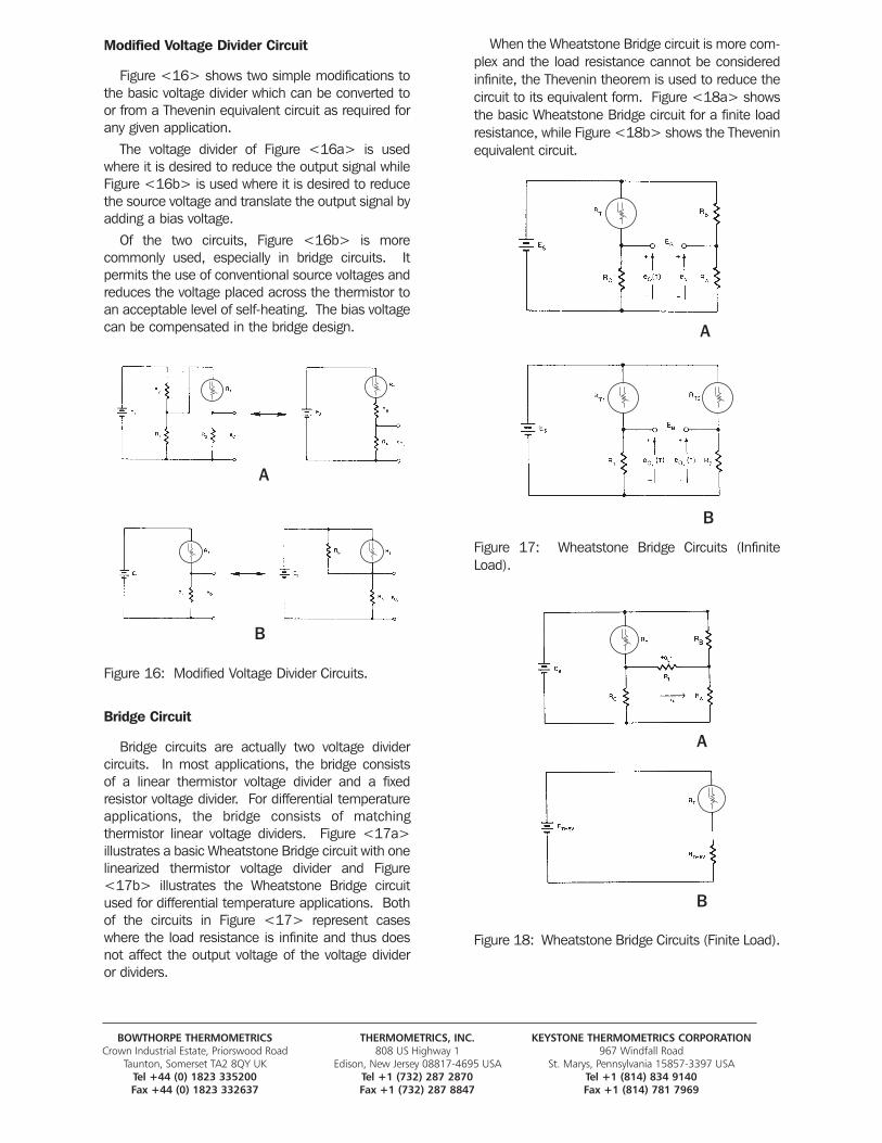
BOWTHORPE THERMOMETRICS THERMOMETRICS, INC. KEYSTONE THERMOMETRICS CORPORATIONCrown Industrial Estate, Priorswood Road 808 US Highway 1 967 Windfall Road
Taunton, Somerset TA2 8QY UK Edison, New Jersey 08817-4695 USA St. Marys, Pennsylvania 15857-3397 USATel +44 (0) 1823 335200 Tel +1 (732) 287 2870 Tel +1 (814) 834 9140Fax +44 (0) 1823 332637 Fax +1 (732) 287 8847 Fax +1 (814) 781 7969
Modified Voltage Divider Circuit
Figure <16> shows two simple modifications tothe basic voltage divider which can be converted toor from a Thevenin equivalent circuit as required forany given application.
The voltage divider of Figure <16a> is usedwhere it is desired to reduce the output signal whileFigure <16b> is used where it is desired to reducethe source voltage and translate the output signal byadding a bias voltage.
Of the two circuits, Figure <16b> is more commonly used, especially in bridge circuits. It permits the use of conventional source voltages andreduces the voltage placed across the thermistor toan acceptable level of self-heating. The bias voltagecan be compensated in the bridge design.
Figure 16: Modified Voltage Divider Circuits.
Bridge Circuit
Bridge circuits are actually two voltage divider circuits. In most applications, the bridge consists of a linear thermistor voltage divider and a fixedresistor voltage divider. For differential temperatureapplications, the bridge consists of matching thermistor linear voltage dividers. Figure <17a>illustrates a basic Wheatstone Bridge circuit with onelinearized thermistor voltage divider and Figure<17b> illustrates the Wheatstone Bridge circuitused for differential temperature applications. Bothof the circuits in Figure <17> represent caseswhere the load resistance is infinite and thus doesnot affect the output voltage of the voltage divider or dividers.
When the Wheatstone Bridge circuit is more com-plex and the load resistance cannot be consideredinfinite, the Thevenin theorem is used to reduce thecircuit to its equivalent form. Figure <18a> showsthe basic Wheatstone Bridge circuit for a finite loadresistance, while Figure <18b> shows the Theveninequivalent circuit.
Figure 17: Wheatstone Bridge Circuits (InfiniteLoad).
Figure 18: Wheatstone Bridge Circuits (Finite Load).
A
A
A
B
B
B
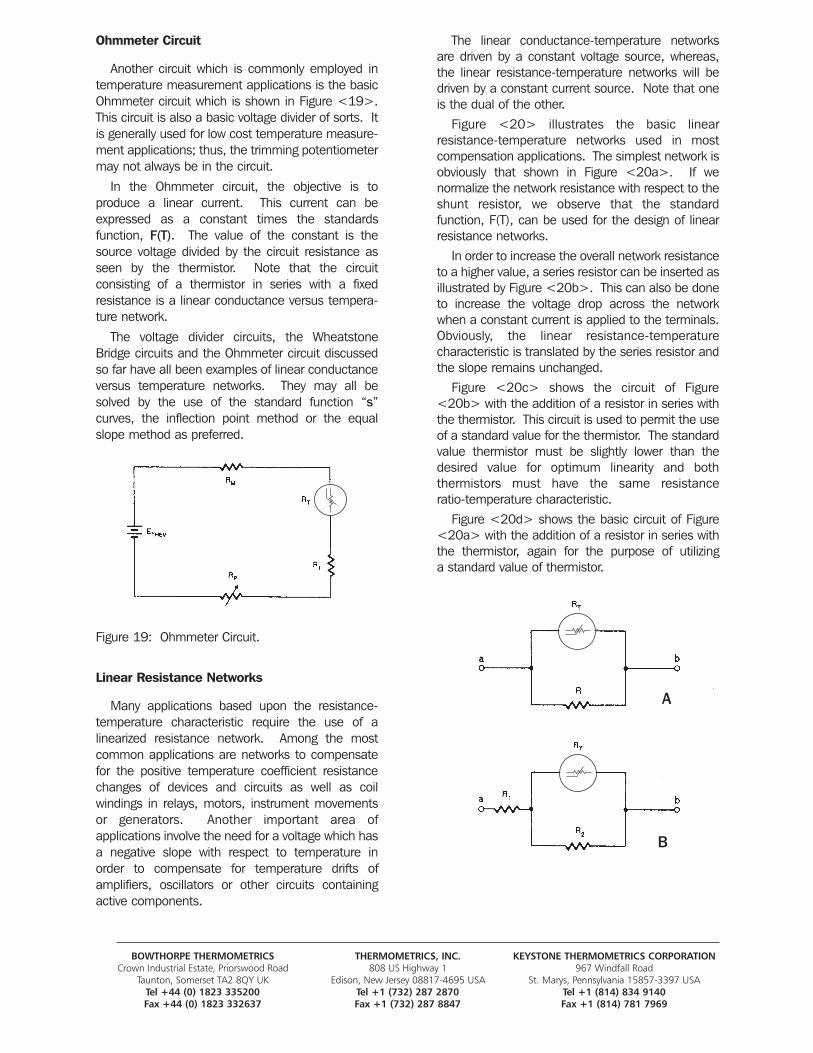
BOWTHORPE THERMOMETRICS THERMOMETRICS, INC. KEYSTONE THERMOMETRICS CORPORATIONCrown Industrial Estate, Priorswood Road 808 US Highway 1 967 Windfall Road
Taunton, Somerset TA2 8QY UK Edison, New Jersey 08817-4695 USA St. Marys, Pennsylvania 15857-3397 USATel +44 (0) 1823 335200 Tel +1 (732) 287 2870 Tel +1 (814) 834 9140Fax +44 (0) 1823 332637 Fax +1 (732) 287 8847 Fax +1 (814) 781 7969
Ohmmeter Circuit
Another circuit which is commonly employed intemperature measurement applications is the basicOhmmeter circuit which is shown in Figure <19>.This circuit is also a basic voltage divider of sorts. Itis generally used for low cost temperature measure-ment applications; thus, the trimming potentiometermay not always be in the circuit.
In the Ohmmeter circuit, the objective is to produce a linear current. This current can beexpressed as a constant times the standards function, F(T). The value of the constant is thesource voltage divided by the circuit resistance asseen by the thermistor. Note that the circuit consisting of a thermistor in series with a fixed resistance is a linear conductance versus tempera-ture network.
The voltage divider circuits, the WheatstoneBridge circuits and the Ohmmeter circuit discussedso far have all been examples of linear conductanceversus temperature networks. They may all besolved by the use of the standard function “s”curves, the inflection point method or the equalslope method as preferred.
Figure 19: Ohmmeter Circuit.
Linear Resistance Networks
Many applications based upon the resistance-temperature characteristic require the use of a linearized resistance network. Among the mostcommon applications are networks to compensatefor the positive temperature coefficient resistancechanges of devices and circuits as well as coil windings in relays, motors, instrument movementsor generators. Another important area of applications involve the need for a voltage which hasa negative slope with respect to temperature inorder to compensate for temperature drifts of amplifiers, oscillators or other circuits containingactive components.
The linear conductance-temperature networksare driven by a constant voltage source, whereas,the linear resistance-temperature networks will bedriven by a constant current source. Note that oneis the dual of the other.
Figure <20> illustrates the basic linear resistance-temperature networks used in most compensation applications. The simplest network isobviously that shown in Figure <20a>. If we normalize the network resistance with respect to theshunt resistor, we observe that the standard function, F(T), can be used for the design of linearresistance networks.
In order to increase the overall network resistanceto a higher value, a series resistor can be inserted asillustrated by Figure <20b>. This can also be doneto increase the voltage drop across the networkwhen a constant current is applied to the terminals.Obviously, the linear resistance-temperature characteristic is translated by the series resistor andthe slope remains unchanged.
Figure <20c> shows the circuit of Figure<20b> with the addition of a resistor in series withthe thermistor. This circuit is used to permit the useof a standard value for the thermistor. The standardvalue thermistor must be slightly lower than thedesired value for optimum linearity and both thermistors must have the same resistance ratio-temperature characteristic.
Figure <20d> shows the basic circuit of Figure<20a> with the addition of a resistor in series withthe thermistor, again for the purpose of utilizing a standard value of thermistor.
A
B
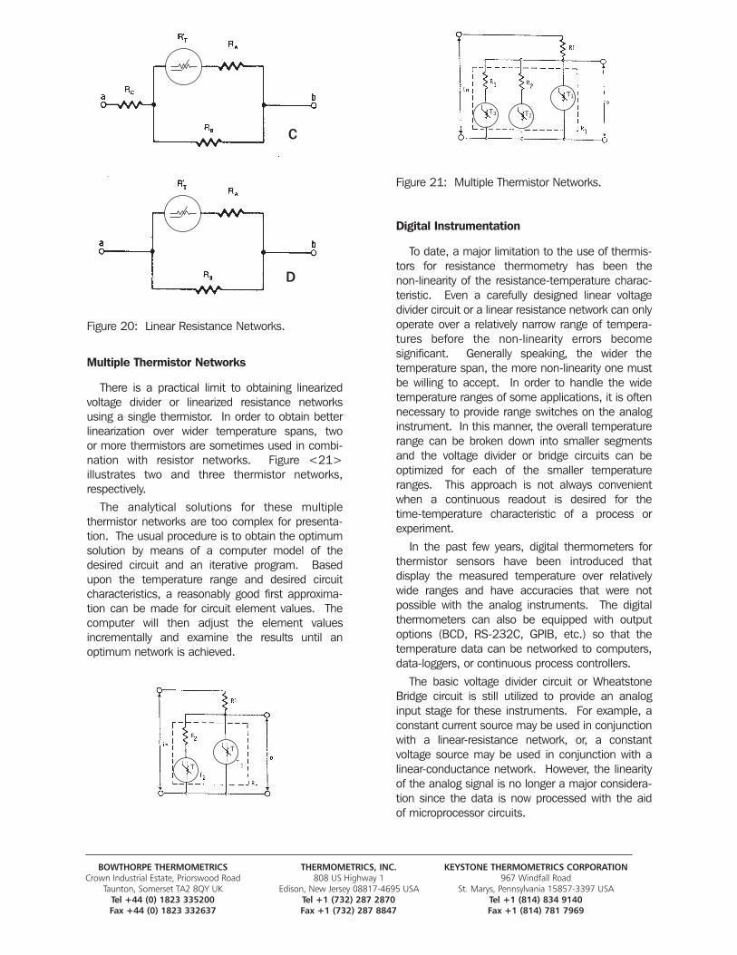
BOWTHORPE THERMOMETRICS THERMOMETRICS, INC. KEYSTONE THERMOMETRICS CORPORATIONCrown Industrial Estate, Priorswood Road 808 US Highway 1 967 Windfall Road
Taunton, Somerset TA2 8QY UK Edison, New Jersey 08817-4695 USA St. Marys, Pennsylvania 15857-3397 USATel +44 (0) 1823 335200 Tel +1 (732) 287 2870 Tel +1 (814) 834 9140Fax +44 (0) 1823 332637 Fax +1 (732) 287 8847 Fax +1 (814) 781 7969
Figure 20: Linear Resistance Networks.
Multiple Thermistor Networks
There is a practical limit to obtaining linearizedvoltage divider or linearized resistance networksusing a single thermistor. In order to obtain betterlinearization over wider temperature spans, two or more thermistors are sometimes used in combi-nation with resistor networks. Figure <21> illustrates two and three thermistor networks, respectively.
The analytical solutions for these multiple thermistor networks are too complex for presenta-tion. The usual procedure is to obtain the optimumsolution by means of a computer model of thedesired circuit and an iterative program. Basedupon the temperature range and desired circuitcharacteristics, a reasonably good first approxima-tion can be made for circuit element values. The computer will then adjust the element values incrementally and examine the results until an optimum network is achieved.
Figure 21: Multiple Thermistor Networks.
Digital Instrumentation
To date, a major limitation to the use of thermis-tors for resistance thermometry has been the non-linearity of the resistance-temperature charac-teristic. Even a carefully designed linear voltagedivider circuit or a linear resistance network can onlyoperate over a relatively narrow range of tempera-tures before the non-linearity errors become significant. Generally speaking, the wider the temperature span, the more non-linearity one mustbe willing to accept. In order to handle the wide temperature ranges of some applications, it is oftennecessary to provide range switches on the analoginstrument. In this manner, the overall temperaturerange can be broken down into smaller segmentsand the voltage divider or bridge circuits can be optimized for each of the smaller temperatureranges. This approach is not always convenientwhen a continuous readout is desired for the time-temperature characteristic of a process orexperiment.
In the past few years, digital thermometers forthermistor sensors have been introduced that display the measured temperature over relativelywide ranges and have accuracies that were not possible with the analog instruments. The digital thermometers can also be equipped with outputoptions (BCD, RS-232C, GPIB, etc.) so that thetemperature data can be networked to computers,data-loggers, or continuous process controllers.
The basic voltage divider circuit or WheatstoneBridge circuit is still utilized to provide an analoginput stage for these instruments. For example, aconstant current source may be used in conjunctionwith a linear-resistance network, or, a constant voltage source may be used in conjunction with alinear-conductance network. However, the linearityof the analog signal is no longer a major considera-tion since the data is now processed with the aid of microprocessor circuits.
T3
T
T
T2
T1
C
D
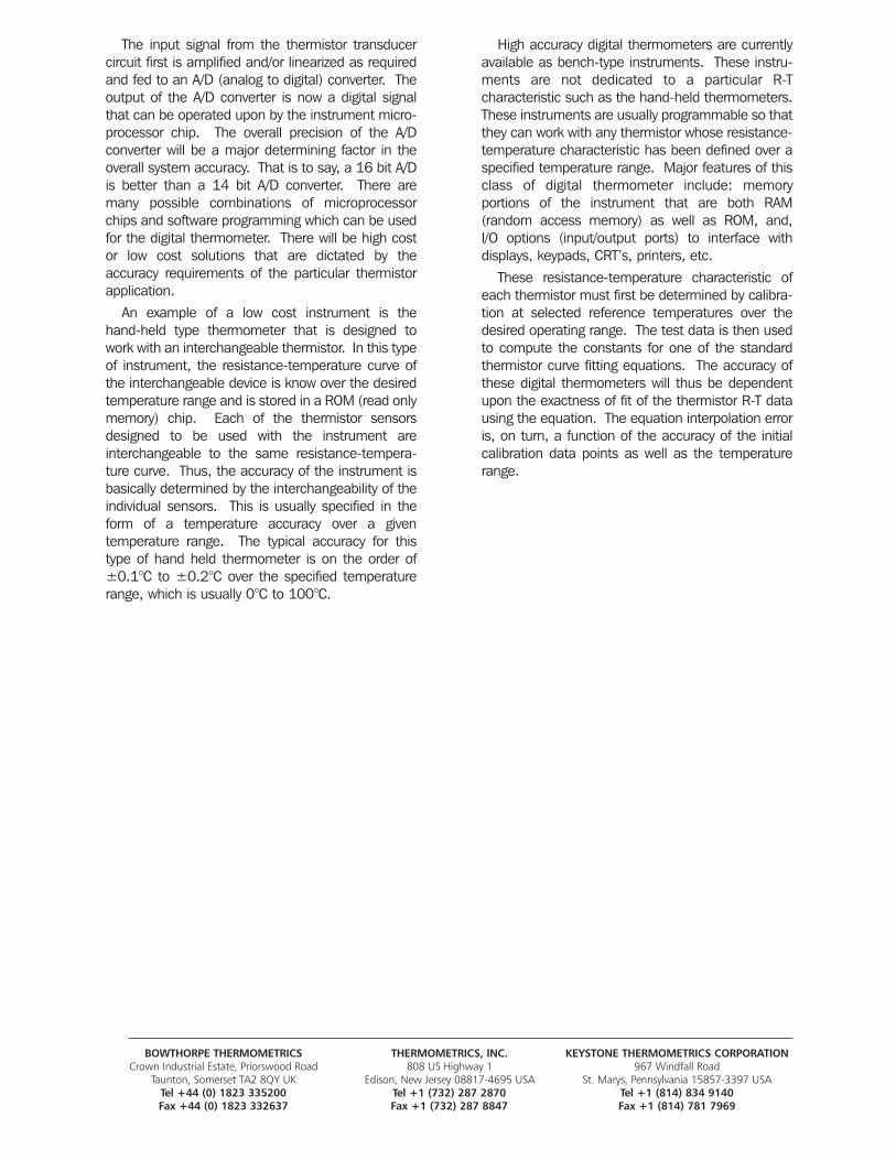
BOWTHORPE THERMOMETRICS THERMOMETRICS, INC. KEYSTONE THERMOMETRICS CORPORATIONCrown Industrial Estate, Priorswood Road 808 US Highway 1 967 Windfall Road
Taunton, Somerset TA2 8QY UK Edison, New Jersey 08817-4695 USA St. Marys, Pennsylvania 15857-3397 USATel +44 (0) 1823 335200 Tel +1 (732) 287 2870 Tel +1 (814) 834 9140Fax +44 (0) 1823 332637 Fax +1 (732) 287 8847 Fax +1 (814) 781 7969
The input signal from the thermistor transducercircuit first is amplified and/or linearized as requiredand fed to an A/D (analog to digital) converter. Theoutput of the A/D converter is now a digital signalthat can be operated upon by the instrument micro-processor chip. The overall precision of the A/D converter will be a major determining factor in theoverall system accuracy. That is to say, a 16 bit A/Dis better than a 14 bit A/D converter. There aremany possible combinations of microprocessorchips and software programming which can be usedfor the digital thermometer. There will be high costor low cost solutions that are dictated by the accuracy requirements of the particular thermistorapplication.
An example of a low cost instrument is the hand-held type thermometer that is designed towork with an interchangeable thermistor. In this typeof instrument, the resistance-temperature curve ofthe interchangeable device is know over the desiredtemperature range and is stored in a ROM (read onlymemory) chip. Each of the thermistor sensorsdesigned to be used with the instrument are interchangeable to the same resistance-tempera-ture curve. Thus, the accuracy of the instrument isbasically determined by the interchangeability of theindividual sensors. This is usually specified in theform of a temperature accuracy over a given temperature range. The typical accuracy for thistype of hand held thermometer is on the order of ±0.1°C to ±0.2°C over the specified temperaturerange, which is usually 0°C to 100°C.
High accuracy digital thermometers are currentlyavailable as bench-type instruments. These instru-ments are not dedicated to a particular R-T characteristic such as the hand-held thermometers.These instruments are usually programmable so thatthey can work with any thermistor whose resistance-temperature characteristic has been defined over aspecified temperature range. Major features of thisclass of digital thermometer include: memory portions of the instrument that are both RAM (random access memory) as well as ROM, and, I/O options (input/output ports) to interface with displays, keypads, CRT’s, printers, etc.
These resistance-temperature characteristic ofeach thermistor must first be determined by calibra-tion at selected reference temperatures over thedesired operating range. The test data is then usedto compute the constants for one of the standardthermistor curve fitting equations. The accuracy ofthese digital thermometers will thus be dependentupon the exactness of fit of the thermistor R-T datausing the equation. The equation interpolation erroris, on turn, a function of the accuracy of the initialcalibration data points as well as the temperaturerange.