ntc thermistors - anysat ntc thermistors r44e.pdf dec.17,2012!note † please read rating and...
TRANSCRIPT
Cat.No.R44E-15
NTC Thermistors
R44E.pdfDec.17,2012
!Note • Please read rating and !CAUTION (for storage, operating, rating, soldering, mounting and handling) in this catalog to prevent smoking and/or burning, etc.• This catalog has only typical specifi cations. Therefore, please approve our product specifi cations or transact the approval sheet for product specifi cations before ordering.
EU RoHS Compliant All the products in this catalog comply with EU RoHS. EU RoHS is "the European Directive 2011/65/EU on the Restriction of the Use
of Certain Hazardous Substances in Electrical and Electronic Equipment." For more details, please refer to our website 'Murata's Approach for EU RoHS'
(http://www.murata.com/info/rohs.html).
R44E.pdfDec.17,2012
!Note • Please read rating and !CAUTION (for storage, operating, rating, soldering, mounting and handling) in this catalog to prevent smoking and/or burning, etc.• This catalog has only typical specifi cations. Therefore, please approve our product specifi cations or transact the approval sheet for product specifi cations before ordering.
CONTENTS
1
2
3
4
5
6
7
Part Numbering 2
Basic Characteristics 6
Temperature Sensor and Compensation 0201 (0603) Size 7
Temperature Sensor and Compensation 0402 (1005) Size 8
Temperature Sensor and Compensation 0603 (1608) Size 10
Temperature Sensor and Compensation 0805 (2012) Size 12
Temperature Sensor and Compensation Chip Type Standard Land Pattern Dimensions 13
Temperature Sensor and Compensation Chip Type Temperature Characteristics (Center Value) 14
Temperature Sensor and Compensation Chip Type !Caution/Notice 18
Temperature Sensor and Compensation Chip Type Package 22
Temperature Sensor Thermo String Type 25
Temperature Sensor Thermo String Type Specifications and Test Methods 26
Temperature Sensor Lead Type 28
Temperature Sensor Lead Type Specifications and Test Methods 29
Temperature Sensor Thermo String/Lead Type Temperature Characteristics (Center Value) 30
Temperature Sensor Thermo String/Lead Type !Caution/Notice 31
Temperature Sensor Thermo String/Lead Type Package 32
Inrush Current Suppression Lead Type 33
Current - R Ratio (RT/R25)/Current - Temperature Characteristics (Typical) 35
Inrush Current Suppression Lead Type !Caution/Notice 38
Inrush Current Suppression Lead Type Package 40
1
2
3
4
5
6
7
R44E.pdfDec.17,2012
!Note • Please read rating and !CAUTION (for storage, operating, rating, soldering, mounting and handling) in this catalog to prevent smoking and/or burning, etc.• This catalog has only typical specifi cations. Therefore, please approve our product specifi cations or transact the approval sheet for product specifi cations before ordering.
2
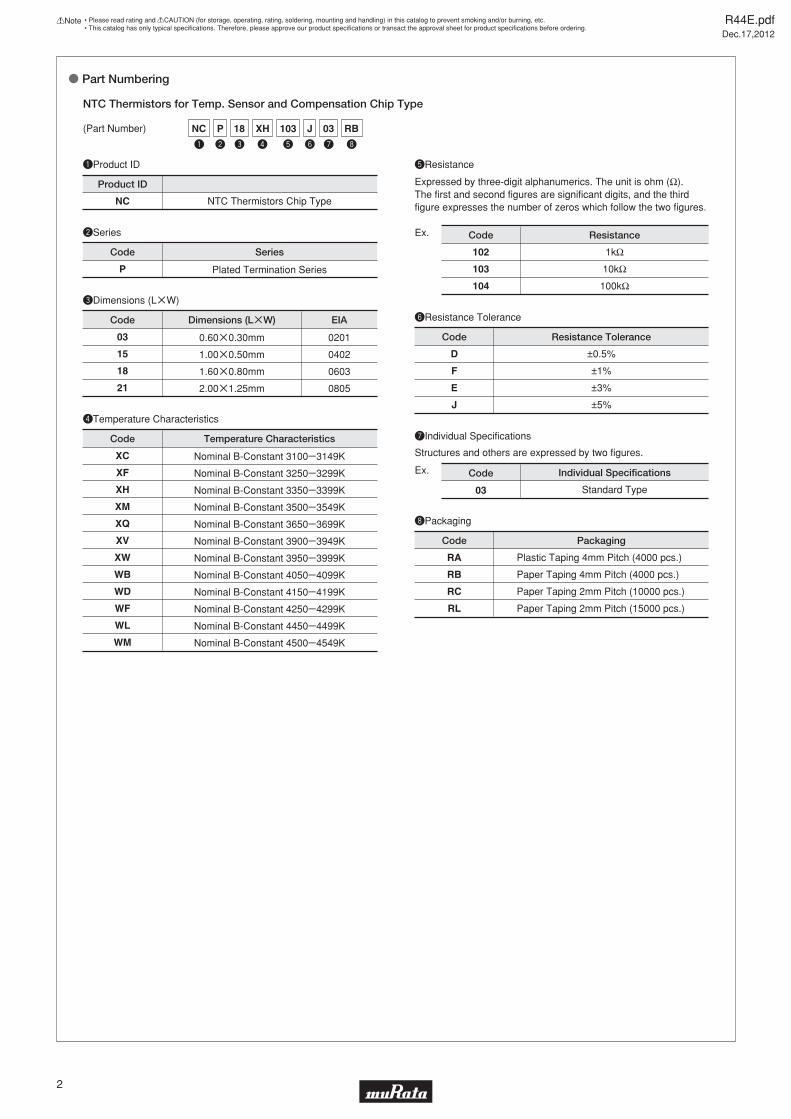
o Part Numbering
qProduct ID
wSeries
yResistance Tolerance
uIndividual Specifications
NTC Thermistors for Temp. Sensor and Compensation Chip Type
NC NTC Thermistors Chip Type
D
F
E
J
P
±0.5%
±1%
±3%
±5%
03
Individual Specifications
Product ID
Code
Code
Series
Resistance Tolerance
Code
(Part Number)
tResistance
Expressed by three-digit alphanumerics. The unit is ohm (Ω). The first and second figures are significant digits, and the third figure expresses the number of zeros which follow the two figures.
Structures and others are expressed by two figures.
102
103
104
Ex.
Ex.
1kΩ
10kΩ
100kΩ
Code Resistance
Standard Type
iPackaging
RA
RB
RC
RL
Plastic Taping 4mm Pitch (4000 pcs.)
Paper Taping 4mm Pitch (4000 pcs.)
Paper Taping 2mm Pitch (10000 pcs.)
Paper Taping 2mm Pitch (15000 pcs.)
Code Packaging
Plated Termination Series
eDimensions (LgW)
03
15
18
21
Code Dimensions (LgW)
0.60g0.30mm
1.00g0.50mm
1.60g0.80mm
2.00g1.25mm
EIA
0201
0402
0603
0805
rTemperature Characteristics
XC
XF
XH
XM
XQ
XV
XW
WB
WD
WF
WL
WM
Code Temperature Characteristics
Nominal B-Constant 3100e3149K
Nominal B-Constant 3250e3299K
Nominal B-Constant 3350e3399K
Nominal B-Constant 3500e3549K
Nominal B-Constant 3650e3699K
Nominal B-Constant 3900e3949K
Nominal B-Constant 3950e3999K
Nominal B-Constant 4050e4099K
Nominal B-Constant 4150e4199K
Nominal B-Constant 4250e4299K
Nominal B-Constant 4450e4499K
Nominal B-Constant 4500e4549K
y
J
e
18
w
P
r
XH
t
103
u
03
i
RBNC
q
R44E.pdfDec.17,2012
!Note • Please read rating and !CAUTION (for storage, operating, rating, soldering, mounting and handling) in this catalog to prevent smoking and/or burning, etc.• This catalog has only typical specifi cations. Therefore, please approve our product specifi cations or transact the approval sheet for product specifi cations before ordering.
3
qProduct ID
wIndividual Specifications
uLead Wire Type
iShape of the Lead Wire Kink
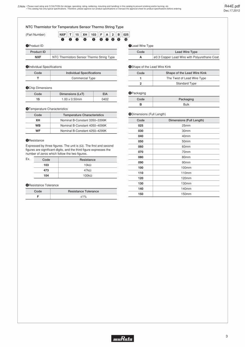
NTC Thermistor for Temperature Sensor Thermo String Type
NXF NTC Thermistors Sensor Thermo String Type A ø0.3 Copper Lead Wire with Polyurethane Coat
1
2
Shape of the Lead Wire Kink
Product ID Code Lead Wire Type
Code
(Part Number)
tResistance
Expressed by three figures. The unit is (Ω). The first and second figures are significant digits, and the third figure expresses the number of zeros which follow the two figures.
103
473
104
Ex.
10kΩ
47kΩ
100kΩ
Code Resistance
The Twist of Lead Wire Type
Standard Type
T Commercial Type
Code
yResistance Tolerance
F ±1%
Code Resistance Tolerance
oPackaging
B Bulk
Code Packaging
!0Dimensions (Full Length)
025
030
040
050
060
070
080
090
100
110
120
130
140
150
25mm
30mm
40mm
50mm
60mm
70mm
80mm
90mm
100mm
110mm
120mm
130mm
140mm
150mm
Code Dimensions (Full Length)
Individual Specifications
rTemperature Characteristics
XH
WB
WF
Nominal B-Constant 3350–3399K
Nominal B-Constant 4050–4099K
Nominal B-Constant 4250–4299K
Code Temperature Characteristics
eChip Dimensions
15 1.00 x 0.50mm
Code Dimensions (LxT)
0402
EIA
t
103
w
T
e
15
r
XH
y
F
u
A
i
2
o
B
!0
025NXF
q
R44E.pdfDec.17,2012
!Note • Please read rating and !CAUTION (for storage, operating, rating, soldering, mounting and handling) in this catalog to prevent smoking and/or burning, etc.• This catalog has only typical specifi cations. Therefore, please approve our product specifi cations or transact the approval sheet for product specifi cations before ordering.
4
qProduct ID
wIndividual Specifications
uLead Wire Type
iShape of the Lead Wire
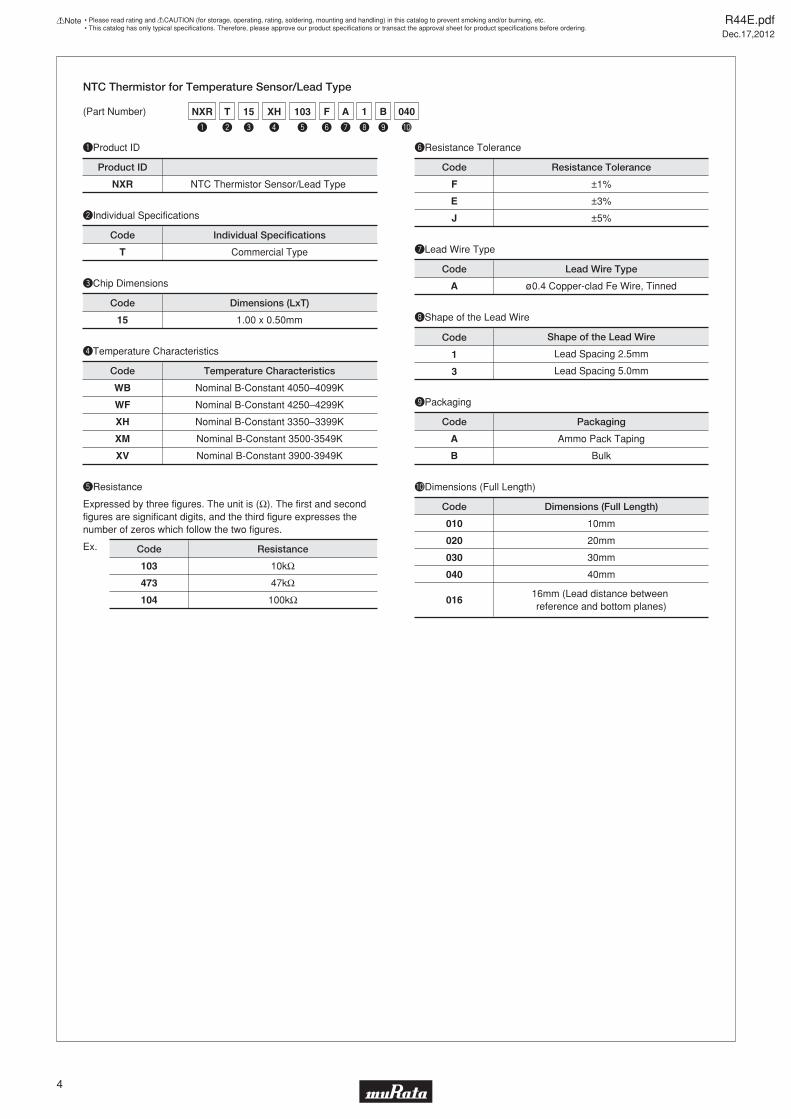
NTC Thermistor for Temperature Sensor/Lead Type
NXR NTC Thermistor Sensor/Lead Type
A ø0.4 Copper-clad Fe Wire, Tinned
1
3
Shape of the Lead Wire
Product ID
Code Lead Wire Type
Code
(Part Number)
tResistance
Expressed by three figures. The unit is (Ω). The first and second figures are significant digits, and the third figure expresses the number of zeros which follow the two figures.
103
473
104
Ex.
10kΩ
47kΩ
100kΩ
Code Resistance
Lead Spacing 2.5mm
Lead Spacing 5.0mm
T Commercial Type
Code
yResistance Tolerance
F
E
J
±1%
±3%
±5%
Code Resistance Tolerance
oPackaging
A
B
Ammo Pack Taping
Bulk
Code Packaging
!0Dimensions (Full Length)
010
020
030
040
016
10mm
20mm
30mm
40mm
16mm (Lead distance between reference and bottom planes)
Code Dimensions (Full Length)
Individual Specifications
rTemperature Characteristics
WB
WF
XH
XM
XV
Nominal B-Constant 4050–4099K
Nominal B-Constant 4250–4299K
Nominal B-Constant 3350–3399K
Nominal B-Constant 3500-3549K
Nominal B-Constant 3900-3949K
Code Temperature Characteristics
eChip Dimensions
15 1.00 x 0.50mm
Code Dimensions (LxT)
t
103
w
T
e
15
r
XH
y
F
u
A
i
1
o
B
!0
040NXR
q
R44E.pdfDec.17,2012
!Note • Please read rating and !CAUTION (for storage, operating, rating, soldering, mounting and handling) in this catalog to prevent smoking and/or burning, etc.• This catalog has only typical specifi cations. Therefore, please approve our product specifi cations or transact the approval sheet for product specifi cations before ordering.
5
y
B0
e
160
r
L
t
BMNT
q w
PA7
qProduct ID
wSeries
rResistance Tolerance
tIndividual Specifications
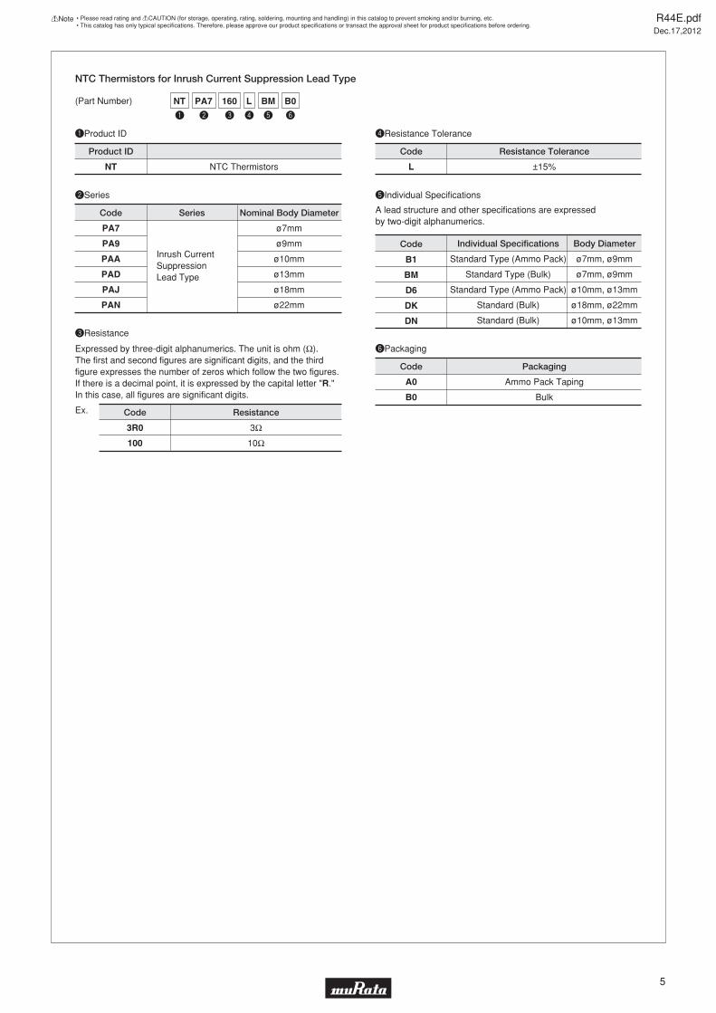
NTC Thermistors for Inrush Current Suppression Lead Type
NT NTC Thermistors L
PA7
PA9
PAA
PAD
PAJ
PAN
±15%
DK
Individual Specifications
Product ID
Code
Code
Series
Resistance Tolerance
Code
(Part Number)
eResistance
Expressed by three-digit alphanumerics. The unit is ohm (Ω). The first and second figures are significant digits, and the third figure expresses the number of zeros which follow the two figures. If there is a decimal point, it is expressed by the capital letter "R." In this case, all figures are significant digits.
A lead structure and other specifications are expressed by two-digit alphanumerics.
3R0
100
Ex.
3Ω
10Ω
Code Resistance
Standard (Bulk)
yPackaging
A0
B0
Ammo Pack Taping
Bulk
Code Packaging
Body Diameter
ø18mm, ø22mm
DN Standard (Bulk) ø10mm, ø13mm
BM Standard Type (Bulk) ø7mm, ø9mm
B1 Standard Type (Ammo Pack) ø7mm, ø9mm
D6 Standard Type (Ammo Pack) ø10mm, ø13mm
Inrush CurrentSuppressionLead Type
ø7mm
ø9mm
ø10mm
ø13mm
ø18mm
ø22mm
Nominal Body Diameter
R44E.pdfDec.17,2012
!Note • Please read rating and !CAUTION (for storage, operating, rating, soldering, mounting and handling) in this catalog to prevent smoking and/or burning, etc.• This catalog has only typical specifi cations. Therefore, please approve our product specifi cations or transact the approval sheet for product specifi cations before ordering.
6
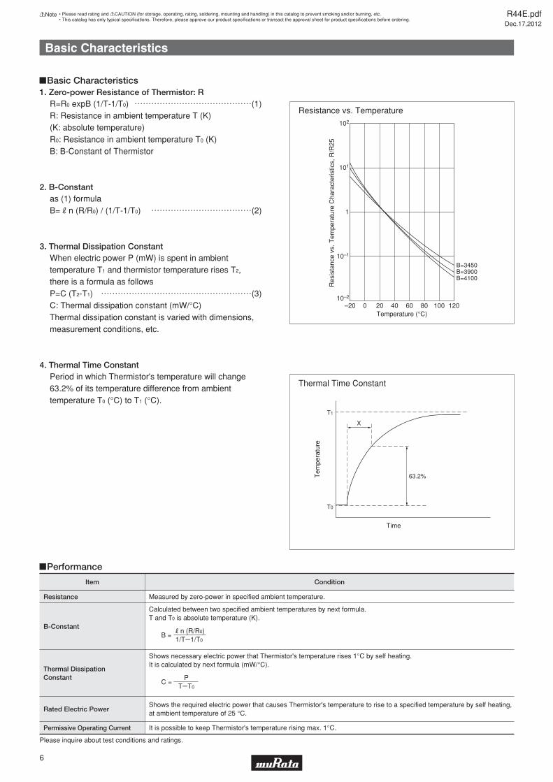
1. Zero-power Resistance of Thermistor: R
2. B-Constant
R=R0 expB (1/T-1/T0) ..............(1)R: Resistance in ambient temperature T (K)(K: absolute temperature)R0: Resistance in ambient temperature T0 (K)B: B-Constant of Thermistor
as (1) formulaB=Rn (R/R0) / (1/T-1/T0) ............(2)
3. Thermal Dissipation ConstantWhen electric power P (mW) is spent in ambient temperature T1 and thermistor temperature rises T2, there is a formula as followsP=C (T2-T1) ..................(3)C: Thermal dissipation constant (mW/°C)Thermal dissipation constant is varied with dimensions, measurement conditions, etc.
4. Thermal Time ConstantPeriod in which Thermistor's temperature will change 63.2% of its temperature difference from ambient temperature T0 (°C) to T1 (°C).
Resistance vs. Temperature
!Basic Characteristics
!Performance
Thermal Time Constant
Item
Resistance
Condition
Measured by zero-power in specified ambient temperature.
Rated Electric PowerShows the required electric power that causes Thermistor's temperature to rise to a specified temperature by self heating, at ambient temperature of 25 °C.
Permissive Operating Current It is possible to keep Thermistor's temperature rising max. 1°C.
Thermal DissipationConstant
Shows necessary electric power that Thermistor's temperature rises 1°C by self heating.It is calculated by next formula (mW/°C).
B-Constant
Calculated between two specified ambient temperatures by next formula.T and T0 is absolute temperature (K).
Rn (R/R0)B =
1/TY1/T0
PC =
TYT0
102
101
Res
ista
nce
vs. T
empe
ratu
re C
hara
cter
istic
s, R
/R25
–20Temperature (°C)
0 20 40 60 80 12010010–2
10–1
1
B=3450B=3900B=4100
Basic Characteristics
T1
T0
Time
63.2%
X
Tem
pera
ture
Please inquire about test conditions and ratings.
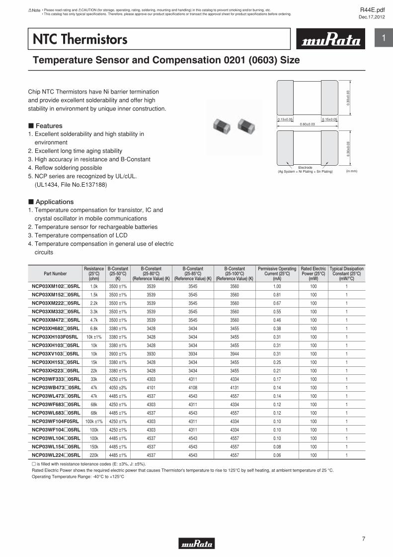
NTC ThermistorsTemperature Sensor and Compensation 0201 (0603) Size
Chip NTC Thermistors have Ni barrier termination and provide excellent solderability and offer high stability in environment by unique inner construction.
c Features1. Excellent solderability and high stability in environment2. Excellent long time aging stability3. High accuracy in resistance and B-Constant4. Refl ow soldering possible5. NCP series are recognized by UL/cUL. (UL1434, File No.E137188)
c Applications1. Temperature compensation for transistor, IC and crystal oscillator in mobile communications2. Temperature sensor for rechargeable batteries3. Temperature compensation of LCD4. Temperature compensation in general use of electric circuits
Electrode(Ag System + Ni Plating + Sn Plating)
0.15±0.05 0.15±0.050.60±0.03
(in mm)
0.30
±0.
030.
30±
0.03
Part NumberResistance
(25°C)(ohm)
B-Constant(25-50°C)
(K)
B-Constant(25-80°C)
(Reference Value) (K)
B-Constant(25-85°C)
(Reference Value) (K)
B-Constant(25-100°C)
(Reference Value) (K)
Permissive OperatingCurrent (25°C)
(mA)
Rated ElectricPower (25°C)
(mW)
Typical DissipationConstant (25°C)
(mW/°C)
NCP03XM102p05RL 1.0k 3500 ±1% 3539 3545 3560 1.00 100 1
NCP03XM152p05RL 1.5k 3500 ±1% 3539 3545 3560 0.81 100 1
NCP03XM222p05RL 2.2k 3500 ±1% 3539 3545 3560 0.67 100 1
NCP03XM332p05RL 3.3k 3500 ±1% 3539 3545 3560 0.55 100 1
NCP03XM472p05RL 4.7k 3500 ±1% 3539 3545 3560 0.46 100 1
NCP03XH682p05RL 6.8k 3380 ±1% 3428 3434 3455 0.38 100 1
NCP03XH103F05RL 10k ±1% 3380 ±1% 3428 3434 3455 0.31 100 1
NCP03XH103p05RL 10k 3380 ±1% 3428 3434 3455 0.31 100 1
NCP03XV103p05RL 10k 3900 ±1% 3930 3934 3944 0.31 100 1
NCP03XH153p05RL 15k 3380 ±1% 3428 3434 3455 0.25 100 1
NCP03XH223p05RL 22k 3380 ±1% 3428 3434 3455 0.21 100 1
NCP03WF333p05RL 33k 4250 ±1% 4303 4311 4334 0.17 100 1
NCP03WB473p05RL 47k 4050 ±3% 4101 4108 4131 0.14 100 1
NCP03WL473p05RL 47k 4485 ±1% 4537 4543 4557 0.14 100 1
NCP03WF683p05RL 68k 4250 ±1% 4303 4311 4334 0.12 100 1
NCP03WL683p05RL 68k 4485 ±1% 4537 4543 4557 0.12 100 1
NCP03WF104F05RL 100k ±1% 4250 ±1% 4303 4311 4334 0.10 100 1
NCP03WF104p05RL 100k 4250 ±1% 4303 4311 4334 0.10 100 1
NCP03WL104p05RL 100k 4485 ±1% 4537 4543 4557 0.10 100 1
NCP03WL154p05RL 150k 4485 ±1% 4537 4543 4557 0.08 100 1
NCP03WL224p05RL 220k 4485 ±1% 4537 4543 4557 0.06 100 1
p is fi lled with resistance tolerance codes (E: ±3%, J: ±5%).
Rated Electric Power shows the required electric power that causes Thermistor's temperature to rise to 125°C by self heating, at ambient temperature of 25 °C.
Operating Temperature Range: -40°C to +125°C
R44E.pdfDec.17,2012
7
!Note • Please read rating and !CAUTION (for storage, operating, rating, soldering, mounting and handling) in this catalog to prevent smoking and/or burning, etc.• This catalog has only typical specifi cations. Therefore, please approve our product specifi cations or transact the approval sheet for product specifi cations before ordering.
1
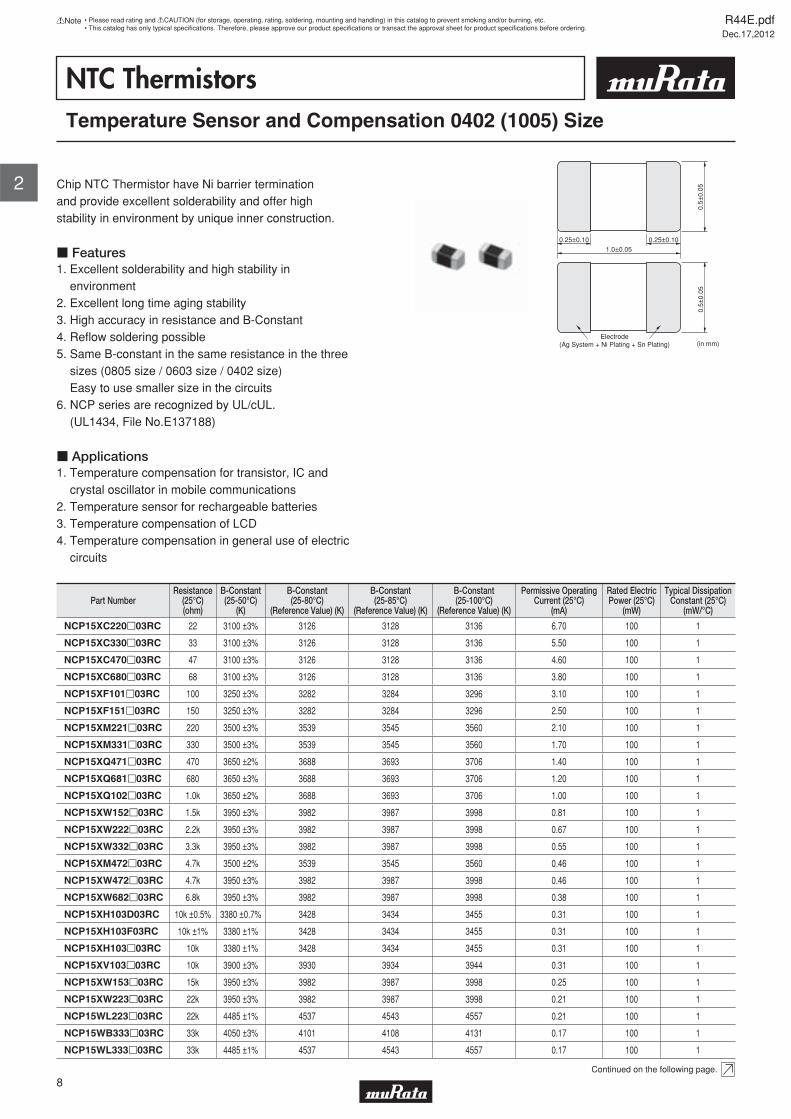
NTC ThermistorsTemperature Sensor and Compensation 0402 (1005) Size
Chip NTC Thermistor have Ni barrier termination and provide excellent solderability and offer high stability in environment by unique inner construction.
c Features1. Excellent solderability and high stability in environment2. Excellent long time aging stability3. High accuracy in resistance and B-Constant4. Refl ow soldering possible5. Same B-constant in the same resistance in the three sizes (0805 size / 0603 size / 0402 size) Easy to use smaller size in the circuits6. NCP series are recognized by UL/cUL. (UL1434, File No.E137188)
c Applications1. Temperature compensation for transistor, IC and crystal oscillator in mobile communications2. Temperature sensor for rechargeable batteries3. Temperature compensation of LCD4. Temperature compensation in general use of electric circuits
Electrode(Ag System + Ni Plating + Sn Plating)
0.25±0.10 0.25±0.101.0±0.05
(in mm)
0.5±
0.05
0.5±
0.05
Part NumberResistance
(25°C)(ohm)
B-Constant(25-50°C)
(K)
B-Constant(25-80°C)
(Reference Value) (K)
B-Constant(25-85°C)
(Reference Value) (K)
B-Constant(25-100°C)
(Reference Value) (K)
Permissive OperatingCurrent (25°C)
(mA)
Rated ElectricPower (25°C)
(mW)
Typical DissipationConstant (25°C)
(mW/°C)
NCP15XC220p03RC 22 3100 ±3% 3126 3128 3136 6.70 100 1
NCP15XC330p03RC 33 3100 ±3% 3126 3128 3136 5.50 100 1
NCP15XC470p03RC 47 3100 ±3% 3126 3128 3136 4.60 100 1
NCP15XC680p03RC 68 3100 ±3% 3126 3128 3136 3.80 100 1
NCP15XF101p03RC 100 3250 ±3% 3282 3284 3296 3.10 100 1
NCP15XF151p03RC 150 3250 ±3% 3282 3284 3296 2.50 100 1
NCP15XM221p03RC 220 3500 ±3% 3539 3545 3560 2.10 100 1
NCP15XM331p03RC 330 3500 ±3% 3539 3545 3560 1.70 100 1
NCP15XQ471p03RC 470 3650 ±2% 3688 3693 3706 1.40 100 1
NCP15XQ681p03RC 680 3650 ±3% 3688 3693 3706 1.20 100 1
NCP15XQ102p03RC 1.0k 3650 ±2% 3688 3693 3706 1.00 100 1
NCP15XW152p03RC 1.5k 3950 ±3% 3982 3987 3998 0.81 100 1
NCP15XW222p03RC 2.2k 3950 ±3% 3982 3987 3998 0.67 100 1
NCP15XW332p03RC 3.3k 3950 ±3% 3982 3987 3998 0.55 100 1
NCP15XM472p03RC 4.7k 3500 ±2% 3539 3545 3560 0.46 100 1
NCP15XW472p03RC 4.7k 3950 ±3% 3982 3987 3998 0.46 100 1
NCP15XW682p03RC 6.8k 3950 ±3% 3982 3987 3998 0.38 100 1
NCP15XH103D03RC 10k ±0.5% 3380 ±0.7% 3428 3434 3455 0.31 100 1
NCP15XH103F03RC 10k ±1% 3380 ±1% 3428 3434 3455 0.31 100 1
NCP15XH103p03RC 10k 3380 ±1% 3428 3434 3455 0.31 100 1
NCP15XV103p03RC 10k 3900 ±3% 3930 3934 3944 0.31 100 1
NCP15XW153p03RC 15k 3950 ±3% 3982 3987 3998 0.25 100 1
NCP15XW223p03RC 22k 3950 ±3% 3982 3987 3998 0.21 100 1
NCP15WL223p03RC 22k 4485 ±1% 4537 4543 4557 0.21 100 1
NCP15WB333p03RC 33k 4050 ±3% 4101 4108 4131 0.17 100 1
NCP15WL333p03RC 33k 4485 ±1% 4537 4543 4557 0.17 100 1
Continued on the following page.
R44E.pdfDec.17,2012
8
!Note • Please read rating and !CAUTION (for storage, operating, rating, soldering, mounting and handling) in this catalog to prevent smoking and/or burning, etc.• This catalog has only typical specifi cations. Therefore, please approve our product specifi cations or transact the approval sheet for product specifi cations before ordering.
2
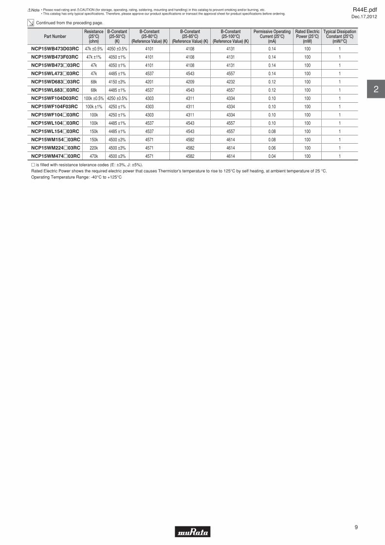
Continued from the preceding page.
Part NumberResistance
(25°C)(ohm)
B-Constant(25-50°C)
(K)
B-Constant(25-80°C)
(Reference Value) (K)
B-Constant(25-85°C)
(Reference Value) (K)
B-Constant(25-100°C)
(Reference Value) (K)
Permissive OperatingCurrent (25°C)
(mA)
Rated ElectricPower (25°C)
(mW)
Typical DissipationConstant (25°C)
(mW/°C)
NCP15WB473D03RC 47k ±0.5% 4050 ±0.5% 4101 4108 4131 0.14 100 1
NCP15WB473F03RC 47k ±1% 4050 ±1% 4101 4108 4131 0.14 100 1
NCP15WB473p03RC 47k 4050 ±1% 4101 4108 4131 0.14 100 1
NCP15WL473p03RC 47k 4485 ±1% 4537 4543 4557 0.14 100 1
NCP15WD683p03RC 68k 4150 ±3% 4201 4209 4232 0.12 100 1
NCP15WL683p03RC 68k 4485 ±1% 4537 4543 4557 0.12 100 1
NCP15WF104D03RC 100k ±0.5% 4250 ±0.5% 4303 4311 4334 0.10 100 1
NCP15WF104F03RC 100k ±1% 4250 ±1% 4303 4311 4334 0.10 100 1
NCP15WF104p03RC 100k 4250 ±1% 4303 4311 4334 0.10 100 1
NCP15WL104p03RC 100k 4485 ±1% 4537 4543 4557 0.10 100 1
NCP15WL154p03RC 150k 4485 ±1% 4537 4543 4557 0.08 100 1
NCP15WM154p03RC 150k 4500 ±3% 4571 4582 4614 0.08 100 1
NCP15WM224p03RC 220k 4500 ±3% 4571 4582 4614 0.06 100 1
NCP15WM474p03RC 470k 4500 ±3% 4571 4582 4614 0.04 100 1
p is fi lled with resistance tolerance codes (E: ±3%, J: ±5%).
Rated Electric Power shows the required electric power that causes Thermistor's temperature to rise to 125°C by self heating, at ambient temperature of 25 °C.
Operating Temperature Range: -40°C to +125°C
R44E.pdfDec.17,2012
9
!Note • Please read rating and !CAUTION (for storage, operating, rating, soldering, mounting and handling) in this catalog to prevent smoking and/or burning, etc.• This catalog has only typical specifi cations. Therefore, please approve our product specifi cations or transact the approval sheet for product specifi cations before ordering.
2
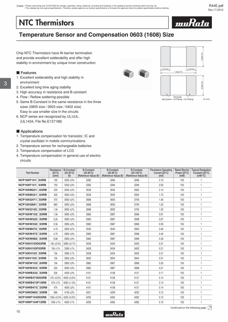
NTC ThermistorsTemperature Sensor and Compensation 0603 (1608) Size
Chip NTC Thermistors have Ni barrier termination and provide excellent solderability and offer high stability in environment by unique inner construction.
c Features1. Excellent solderability and high stability in environment2. Excellent long time aging stability3. High accuracy in resistance and B-constant4. Flow / Refl ow soldering possible5. Same B-Constant in the same resistance in the three sizes (0805 size / 0603 size / 0402 size) Easy to use smaller size in the circuits6. NCP series are recognized by UL/cUL. (UL1434, File No.E137188)
c Applications1. Temperature compensation for transistor, IC and crystal oscillator in mobile communications2. Temperature sensor for rechargeable batteries3. Temperature compensation of LCD4. Temperature compensation in general use of electric circuits
Electrode(Ag System + Ni Plating + Sn Plating)
0.2-0.6 0.2-0.61.6±0.15
(in mm)
0.8±
0.15
0.8±
0.15
Part NumberResistance
(25°C)(ohm)
B-Constant(25-50°C)
(K)
B-Constant(25-80°C)
(Reference Value) (K)
B-Constant(25-85°C)
(Reference Value) (K)
B-Constant(25-100°C)
(Reference Value) (K)
Permissive OperatingCurrent (25°C)
(mA)
Rated ElectricPower (25°C)
(mW)
Typical DissipationConstant (25°C)
(mW/°C)
NCP18XF101p03RB 100 3250 ±3% 3282 3284 3296 3.10 100 1
NCP18XF151p03RB 150 3250 ±3% 3282 3284 3296 2.50 100 1
NCP18XM221p03RB 220 3500 ±3% 3539 3545 3560 2.10 100 1
NCP18XM331p03RB 330 3500 ±3% 3539 3545 3560 1.70 100 1
NCP18XQ471p03RB 470 3650 ±2% 3688 3693 3706 1.40 100 1
NCP18XQ681p03RB 680 3650 ±3% 3688 3693 3706 1.20 100 1
NCP18XQ102p03RB 1.0k 3650 ±2% 3688 3693 3706 1.00 100 1
NCP18XW152p03RB 1.5k 3950 ±3% 3982 3987 3998 0.81 100 1
NCP18XW222p03RB 2.2k 3950 ±3% 3982 3987 3998 0.67 100 1
NCP18XW332p03RB 3.3k 3950 ±3% 3982 3987 3998 0.55 100 1
NCP18XM472p03RB 4.7k 3500 ±2% 3539 3545 3560 0.46 100 1
NCP18XW472p03RB 4.7k 3950 ±3% 3982 3987 3998 0.46 100 1
NCP18XW682p03RB 6.8k 3950 ±3% 3982 3987 3998 0.38 100 1
NCP18XH103D03RB 10k ±0.5% 3380 ±0.7% 3428 3434 3455 0.31 100 1
NCP18XH103F03RB 10k ±1% 3380 ±1% 3428 3434 3455 0.31 100 1
NCP18XH103p03RB 10k 3380 ±1% 3428 3434 3455 0.31 100 1
NCP18XV103p03RB 10k 3900 ±3% 3930 3934 3944 0.31 100 1
NCP18XW153p03RB 15k 3950 ±3% 3982 3987 3998 0.25 100 1
NCP18XW223p03RB 22k 3950 ±3% 3982 3987 3998 0.21 100 1
NCP18WB333p03RB 33k 4050 ±3% 4101 4108 4131 0.17 100 1
NCP18WB473D03RB 47k ±0.5% 4030 ±0.5% 4101 4108 4131 0.14 100 1
NCP18WB473F10RB 47k ±1% 4050 ±1.5% 4101 4108 4131 0.14 100 1
NCP18WB473p03RB 47k 4050 ±2% 4101 4108 4131 0.14 100 1
NCP18WD683p03RB 68k 4150 ±3% 4201 4209 4232 0.12 100 1
NCP18WF104D03RB 100k ±0.5% 4200 ±0.5% 4255 4260 4282 0.10 100 1
NCP18WF104F12RB 100k ±1% 4200 ±1% 4255 4260 4282 0.10 100 1
Continued on the following page.
R44E.pdfDec.17,2012
10
!Note • Please read rating and !CAUTION (for storage, operating, rating, soldering, mounting and handling) in this catalog to prevent smoking and/or burning, etc.• This catalog has only typical specifi cations. Therefore, please approve our product specifi cations or transact the approval sheet for product specifi cations before ordering.
3
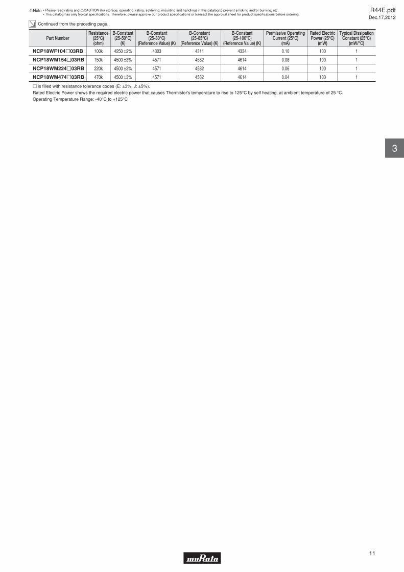
Continued from the preceding page.
Part NumberResistance
(25°C)(ohm)
B-Constant(25-50°C)
(K)
B-Constant(25-80°C)
(Reference Value) (K)
B-Constant(25-85°C)
(Reference Value) (K)
B-Constant(25-100°C)
(Reference Value) (K)
Permissive OperatingCurrent (25°C)
(mA)
Rated ElectricPower (25°C)
(mW)
Typical DissipationConstant (25°C)
(mW/°C)
NCP18WF104p03RB 100k 4250 ±2% 4303 4311 4334 0.10 100 1
NCP18WM154p03RB 150k 4500 ±3% 4571 4582 4614 0.08 100 1
NCP18WM224p03RB 220k 4500 ±3% 4571 4582 4614 0.06 100 1
NCP18WM474p03RB 470k 4500 ±3% 4571 4582 4614 0.04 100 1
p is fi lled with resistance tolerance codes (E: ±3%, J: ±5%).
Rated Electric Power shows the required electric power that causes Thermistor's temperature to rise to 125°C by self heating, at ambient temperature of 25 °C.
Operating Temperature Range: -40°C to +125°C
R44E.pdfDec.17,2012
11
!Note • Please read rating and !CAUTION (for storage, operating, rating, soldering, mounting and handling) in this catalog to prevent smoking and/or burning, etc.• This catalog has only typical specifi cations. Therefore, please approve our product specifi cations or transact the approval sheet for product specifi cations before ordering.
3
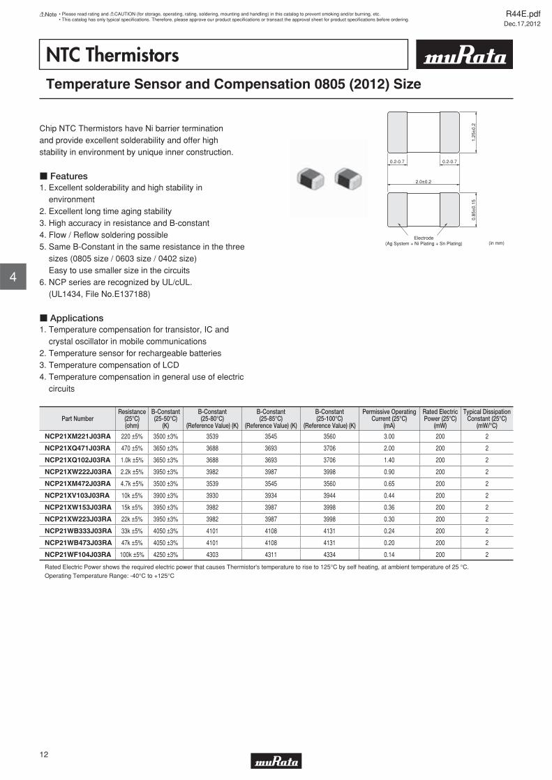
NTC ThermistorsTemperature Sensor and Compensation 0805 (2012) Size
Chip NTC Thermistors have Ni barrier termination and provide excellent solderability and offer high stability in environment by unique inner construction.
c Features1. Excellent solderability and high stability in environment2. Excellent long time aging stability3. High accuracy in resistance and B-constant4. Flow / Refl ow soldering possible5. Same B-Constant in the same resistance in the three sizes (0805 size / 0603 size / 0402 size) Easy to use smaller size in the circuits6. NCP series are recognized by UL/cUL. (UL1434, File No.E137188)
c Applications1. Temperature compensation for transistor, IC and crystal oscillator in mobile communications2. Temperature sensor for rechargeable batteries3. Temperature compensation of LCD4. Temperature compensation in general use of electric circuits
2.0±0.2
0.2-0.7 0.2-0.7
Electrode(Ag System + Ni Plating + Sn Plating)
1.25
±0.
20.
85±
0.15
(in mm)
Part NumberResistance
(25°C)(ohm)
B-Constant(25-50°C)
(K)
B-Constant(25-80°C)
(Reference Value) (K)
B-Constant(25-85°C)
(Reference Value) (K)
B-Constant(25-100°C)
(Reference Value) (K)
Permissive OperatingCurrent (25°C)
(mA)
Rated ElectricPower (25°C)
(mW)
Typical DissipationConstant (25°C)
(mW/°C)
NCP21XM221J03RA 220 ±5% 3500 ±3% 3539 3545 3560 3.00 200 2
NCP21XQ471J03RA 470 ±5% 3650 ±3% 3688 3693 3706 2.00 200 2
NCP21XQ102J03RA 1.0k ±5% 3650 ±3% 3688 3693 3706 1.40 200 2
NCP21XW222J03RA 2.2k ±5% 3950 ±3% 3982 3987 3998 0.90 200 2
NCP21XM472J03RA 4.7k ±5% 3500 ±3% 3539 3545 3560 0.65 200 2
NCP21XV103J03RA 10k ±5% 3900 ±3% 3930 3934 3944 0.44 200 2
NCP21XW153J03RA 15k ±5% 3950 ±3% 3982 3987 3998 0.36 200 2
NCP21XW223J03RA 22k ±5% 3950 ±3% 3982 3987 3998 0.30 200 2
NCP21WB333J03RA 33k ±5% 4050 ±3% 4101 4108 4131 0.24 200 2
NCP21WB473J03RA 47k ±5% 4050 ±3% 4101 4108 4131 0.20 200 2
NCP21WF104J03RA 100k ±5% 4250 ±3% 4303 4311 4334 0.14 200 2
Rated Electric Power shows the required electric power that causes Thermistor's temperature to rise to 125°C by self heating, at ambient temperature of 25 °C.
Operating Temperature Range: -40°C to +125°C
R44E.pdfDec.17,2012
12
!Note • Please read rating and !CAUTION (for storage, operating, rating, soldering, mounting and handling) in this catalog to prevent smoking and/or burning, etc.• This catalog has only typical specifi cations. Therefore, please approve our product specifi cations or transact the approval sheet for product specifi cations before ordering.
4
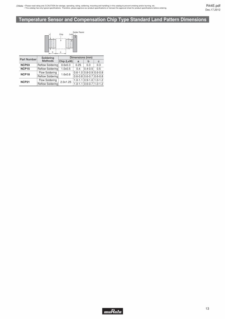
Temperature Sensor and Compensation Chip Type Standard Land Pattern Dimensions
Chip LandSolder Resist
b a
c
Part Number SolderingMethods Chip (LxW)
Dimensions (mm)a b c
NCP03NCP15
NCP18
NCP21
Reflow SolderingReflow SolderingFlow Soldering
Reflow SolderingFlow Soldering
Reflow Soldering
0.6x0.31.0x0.5
1.6x0.8
2.0x1.25
0.250.4
0.6-1.00.6-0.81.0-1.11.0-1.1
0.30.4-0.50.8-0.90.6-0.70.9-1.00.6-0.7
0.30.5
0.6-0.80.6-0.81.0-1.21.0-1.2
R44E.pdfDec.17,2012
13
!Note • Please read rating and !CAUTION (for storage, operating, rating, soldering, mounting and handling) in this catalog to prevent smoking and/or burning, etc.• This catalog has only typical specifi cations. Therefore, please approve our product specifi cations or transact the approval sheet for product specifi cations before ordering.
Y40Y35Y30Y25Y20Y15Y10Y505101520253035404550556065707580859095100105110115120125
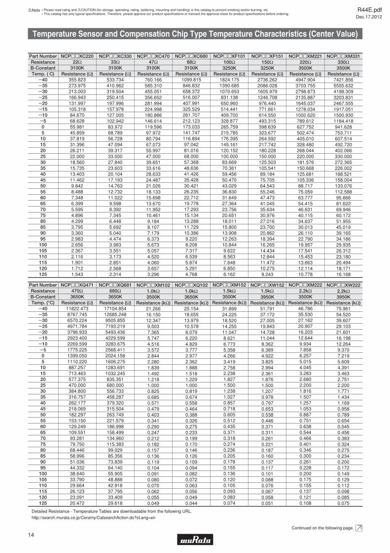
Temp. ( C)B-ConstantResistance
Part Number
355.823273.975213.003166.943131.997105.31884.67068.62855.98145.85937.81931.39626.21122.00018.56015.73513.40311.4629.8428.4887.3486.3995.5954.8964.2993.7953.3602.9832.6562.3672.1161.9011.7121.543
NCPppXC220
Resistance (Ω)533.734410.962319.504250.415197.996157.978127.005102.94283.97268.78956.72847.09439.31733.00027.84023.60320.10417.19314.76312.73211.0229.5988.3927.3456.4485.6925.0404.4743.9833.5513.1732.8512.5682.314
NCPppXC330
Resistance (Ω)760.166585.310455.051356.652281.994224.998180.886146.614119.59697.97280.79467.07355.99747.00039.65133.61628.63324.48721.02618.13315.69813.67011.95210.4619.1848.1077.1796.3735.6735.0574.5204.0603.6573.296
NCPppXC470
Resistance (Ω)
Y40Y35Y30Y25Y20Y15Y10Y505101520253035404550556065707580859095100105110115120125
11822.4738767.7456570.2244971.7843796.9332923.4002269.5991775.2251399.0501110.220887.257713.463577.375470.000384.800316.757262.177218.069182.297153.150129.249109.55193.28179.75068.44658.99651.03644.33238.64033.79029.66426.12323.09120.472
NCPppXQ471
Resistance (Ω)17104.85412685.2489505.8557193.2195493.4364229.5993283.6752568.4112024.1581606.2751283.6911032.245835.351680.000556.733458.287379.320315.504263.749221.579186.998158.499134.960115.38399.02985.35673.83964.14055.90548.88842.91837.79533.40929.618
NCPppXQ681
Resistance (Ω)
Continued on the following page.
3100K 3100K 3100K
3650K 3650K
22Ω 33Ω 47Ω
470Ω 680Ω
Temp. (°C)B-ConstantResistance
Part Number
1099.815846.832658.372516.007407.991325.529261.707212.123173.033141.747116.89497.04281.01668.00057.36848.63641.42635.42830.42126.23522.71219.77817.29315.13413.28811.72910.3869.2208.2087.3176.5395.8745.2914.768
NCPppXC680
Resistance (Ω)3100K68Ω
1824.1751390.6851070.653831.138650.960514.441409.700328.877265.759215.785176.395145.161120.152100.00083.66970.36159.45650.47043.02936.83031.64927.36423.75620.65118.01115.80013.90812.26310.8449.6228.5637.6486.8506.162
NCPppXF101
Resistance (Ω)2736.2622086.0281605.9791246.708976.440771.661614.550493.315398.639323.677264.592217.742180.228150.000125.503105.54189.18475.70564.54355.24647.47341.04535.63430.97627.01623.70020.86218.39416.26514.43412.84411.47210.2759.243
NCPppXF151
Resistance (Ω)4947.9043703.7552798.8732135.8871645.0371278.0341000.620789.612627.752502.474405.010328.480268.044220.000181.576150.668125.681105.33688.71775.05963.77754.41546.63140.11534.63730.01326.11022.79019.95717.54115.45313.66312.11410.778
NCPppXM221
Resistance (Ω)7421.8565555.6324198.3093203.8312467.5551917.0511500.9301184.418941.628753.711607.514492.720402.066330.000272.365226.002188.521158.004133.076112.58895.66681.62269.94660.17251.95545.01939.16534.18629.93526.31223.18020.49418.17116.168
NCPppXM331
Resistance (Ω)3250K 3250K 3500K 3500K100Ω 150Ω 220Ω 330Ω
75.96154.52039.60729.10321.60116.19812.2649.3707.2195.6094.3913.4632.7512.2001.7711.4341.1690.9580.7890.6540.5450.4560.3830.3240.2750.2340.2000.1720.1490.1290.1120.0980.0850.075
NCPppXW222
Resistance (kΩ)25.15418.65513.97910.5788.0796.2204.8293.7772.9772.3621.8881.5181.2291.0000.8190.6740.5580.4640.3880.3260.2750.2330.1990.1700.1460.1260.1090.0940.0820.0720.0630.0560.0490.044
NCPppXQ102
Resistance (kΩ)51.79137.17227.00519.84314.72811.0448.3626.3894.9223.8252.9942.3611.8761.5001.2070.9780.7970.6530.5380.4460.3710.3110.2610.2210.1870.1600.1370.1170.1010.0880.0760.0670.0580.051
NCPppXW152
Resistance (kΩ)3950K3650K 3950K2.2kΩ1.0kΩ
21.26616.15012.3479.5037.3655.7474.5163.5722.8442.2801.8391.4921.2181.0000.8250.6850.5710.4790.4030.3410.2900.2470.2120.1820.1570.1360.1190.1040.0910.0800.0700.0620.0550.049
NCPppXM102
Resistance (kΩ)3500K1.0kΩ
31.89924.22518.52014.25511.0478.6216.7735.3584.2663.4192.7582.2381.8271.5001.2381.0270.8570.7180.6050.5120.4350.3710.3180.2740.2360.2050.1780.1550.1360.1200.1050.0930.0830.074
NCPppXM152
Resistance (kΩ)3500K1.5kΩ
46.78635.53027.16220.90716.20312.6449.9347.8586.2575.0154.0453.2832.6802.2001.8161.5071.2571.0530.8870.7510.6380.5440.4660.4010.3460.3000.2610.2280.2000.1750.1550.1370.1210.108
NCPppXM222
Resistance (kΩ)3500K2.2kΩ1.5kΩ
Detailed Resistance - Temperature Tables are downloadable from the following URL.
http://search.murata.co.jp/Ceramy/CatsearchAction.do?sLang=en
R44E.pdfDec.17,2012
14
!Note • Please read rating and !CAUTION (for storage, operating, rating, soldering, mounting and handling) in this catalog to prevent smoking and/or burning, etc.• This catalog has only typical specifi cations. Therefore, please approve our product specifi cations or transact the approval sheet for product specifi cations before ordering.
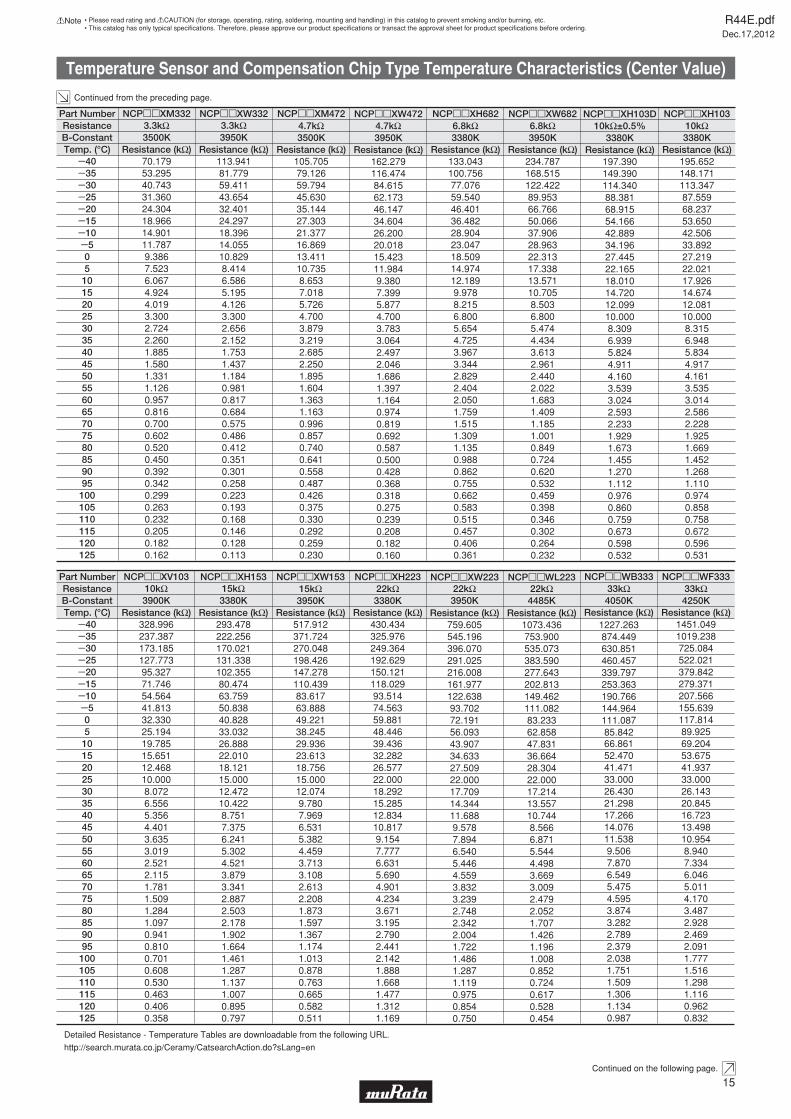
Temperature Sensor and Compensation Chip Type Temperature Characteristics (Center Value)
Continued from the preceding page.
Y40Y35Y30Y25Y20Y15Y10Y505101520253035404550556065707580859095100105110115120125
113.94181.77959.41143.65432.40124.29718.39614.05510.8298.4146.5865.1954.1263.3002.6562.1521.7531.4371.1840.9810.8170.6840.5750.4860.4120.3510.3010.2580.2230.1930.1680.1460.1280.113
NCPppXW332
Resistance (kΩ)
NCPppXV103
328.996237.387173.185127.77395.32771.74654.56441.81332.33025.19419.78515.65112.46810.0008.0726.5565.3564.4013.6353.0192.5212.1151.7811.5091.2841.0970.9410.8100.7010.6080.5300.4630.4060.358
Resistance (kΩ)293.478222.256170.021131.338102.35580.47463.75950.83840.82833.03226.88822.01018.12115.00012.47210.4228.7517.3756.2415.3024.5213.8793.3412.8872.5032.1781.9021.6641.4611.2871.1371.0070.8950.797
NCPppXH153
Resistance (kΩ)Y40Y35Y30Y25Y20Y15Y10Y505101520253035404550556065707580859095100105110115120125
Continued on the following page.
3950K
3900K 3380K
3.3kΩ
10kΩ 15kΩ
70.17953.29540.74331.36024.30418.96614.90111.7879.3867.5236.0674.9244.0193.3002.7242.2601.8851.5801.3311.1260.9570.8160.7000.6020.5200.4500.3920.3420.2990.2630.2320.2050.1820.162
NCPppXM332
Resistance (kΩ)3500K3.3kΩ
Temp. (°C)B-ConstantResistance
Part Number
Temp. (°C)B-ConstantResistance
Part Number
NCPppXM472
105.70579.12659.79445.63035.14427.30321.37716.86913.41110.7358.6537.0185.7264.7003.8793.2192.6852.2501.8951.6041.3631.1630.9960.8570.7400.6410.5580.4870.4260.3750.3300.2920.2590.230
Resistance (kΩ)133.043100.75677.07659.54046.40136.48228.90423.04718.50914.97412.1899.9788.2156.8005.6544.7253.9673.3442.8292.4042.0501.7591.5151.3091.1350.9880.8620.7550.6620.5830.5150.4570.4060.361
NCPppXH682
Resistance (kΩ)234.787168.515122.42289.95366.76650.06637.90628.96322.31317.33813.57110.7058.5036.8005.4744.4343.6132.9612.4402.0221.6831.4091.1851.0010.8490.7240.6200.5320.4590.3980.3460.3020.2640.232
NCPppXW682
Resistance (kΩ)195.652148.171113.34787.55968.23753.65042.50633.89227.21922.02117.92614.67412.08110.0008.3156.9485.8344.9174.1613.5353.0142.5862.2281.9251.6691.4521.2681.1100.9740.8580.7580.6720.5960.531
NCPppXH103
Resistance (kΩ)3500K 3380K 3950K 3380K4.7kΩ
NCPppXW472
162.279116.47484.61562.17346.14734.60426.20020.01815.42311.9849.3807.3995.8774.7003.7833.0642.4972.0461.6861.3971.1640.9740.8190.6920.5870.5000.4280.3680.3180.2750.2390.2080.1820.160
Resistance (kΩ)3950K4.7kΩ 6.8kΩ 6.8kΩ 10kΩ
197.390149.390114.34088.38168.91554.16642.88934.19627.44522.16518.01014.72012.09910.0008.3096.9395.8244.9114.1603.5393.0242.5932.2331.9291.6731.4551.2701.1120.9760.8600.7590.6730.5980.532
NCPppXH103D
Resistance (kΩ)3380K
10kΩ±0.5%
NCPppXW223
759.605545.196396.070291.025216.008161.977122.63893.70272.19156.09343.90734.63327.50922.00017.70914.34411.6889.5787.8946.5405.4464.5593.8323.2392.7482.3422.0041.7221.4861.2871.1190.9750.8540.750
Resistance (kΩ)1073.436753.900535.073383.590277.643202.813149.462111.08283.23362.85847.83136.66428.30422.00017.21413.55710.7448.5666.8715.5444.4983.6693.0092.4792.0521.7071.4261.1961.0080.8520.7240.6170.5280.454
NCPppWL223
Resistance (kΩ)1227.263874.449630.851460.457339.797253.363190.766144.964111.08785.84266.86152.47041.47133.00026.43021.29817.26614.07611.5389.5067.8706.5495.4754.5953.8743.2822.7892.3792.0381.7511.5091.3061.1340.987
NCPppWB333
Resistance (kΩ)1451.0491019.238725.084522.021379.842279.371207.566155.639117.81489.92569.20453.67541.93733.00026.14320.84516.72313.49810.9548.9407.3346.0465.0114.1703.4872.9282.4692.0911.7771.5161.2981.1160.9620.832
NCPppWF333
Resistance (kΩ)3950K 4485K 4050K 4250K22kΩ 22kΩ 33kΩ 33kΩ
430.434325.976249.364192.629150.121118.02993.51474.56359.88148.44639.43632.28226.57722.00018.29215.28512.83410.8179.1547.7776.6315.6904.9014.2343.6713.1952.7902.4412.1421.8881.6681.4771.3121.169
NCPppXH223
Resistance (kΩ)3380K22kΩ
517.912371.724270.048198.426147.278110.43983.61763.88849.22138.24529.93623.61318.75615.00012.0749.7807.9696.5315.3824.4593.7133.1082.6132.2081.8731.5971.3671.1741.0130.8780.7630.6650.5820.511
NCPppXW153
Resistance (kΩ)3950K15kΩ
Detailed Resistance - Temperature Tables are downloadable from the following URL.
http://search.murata.co.jp/Ceramy/CatsearchAction.do?sLang=en
R44E.pdfDec.17,2012
15
!Note • Please read rating and !CAUTION (for storage, operating, rating, soldering, mounting and handling) in this catalog to prevent smoking and/or burning, etc.• This catalog has only typical specifi cations. Therefore, please approve our product specifi cations or transact the approval sheet for product specifi cations before ordering.
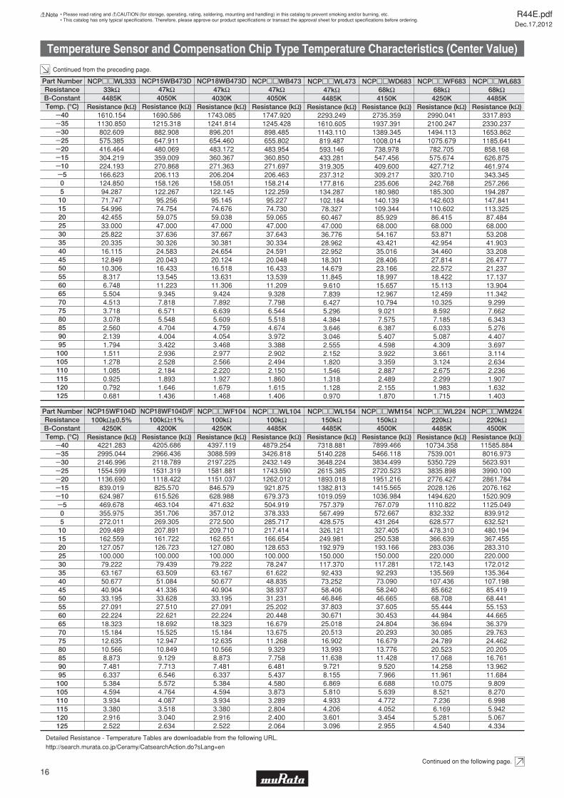
Temperature Sensor and Compensation Chip Type Temperature Characteristics (Center Value)
Continued from the preceding page.
Y40Y35Y30Y25Y20Y15Y10Y505101520253035404550556065707580859095100105110115120125
Y40Y35Y30Y25Y20Y15Y10Y505101520253035404550556065707580859095100105110115120125
1610.1541130.850802.609575.385416.464304.219224.193166.623124.85094.28771.74754.99642.45533.00025.82220.33516.11512.84910.3068.3176.7485.5044.5133.7183.0782.5602.1391.7941.5111.2781.0850.9250.7920.681
NCPppWL333
Resistance (kΩ)1747.9201245.428898.485655.802483.954360.850271.697206.463158.214122.25995.22774.73059.06547.00037.64330.33424.59120.04816.43313.53911.2099.3287.7986.5445.5184.6743.9723.3882.9022.4942.1501.8601.6151.406
NCPppWB473
Resistance (kΩ)4485K 4050K33kΩ 47kΩ
Temp. (°C)B-ConstantResistance
Part Number
Temp. (°C)B-ConstantResistance
Part Number NCPppWF104
4397.1193088.5992197.2251581.8811151.037846.579628.988471.632357.012272.500209.710162.651127.080100.00079.22263.16750.67740.90433.19527.09122.22418.32315.18412.63510.5668.8737.4816.3375.3844.5943.9343.3802.9162.522
Resistance (kΩ)4250K100kΩ
NCP15WF104D
4221.2832995.0442146.9961554.5991136.690839.019624.987469.678355.975272.011209.489162.559127.057100.00079.22263.16750.67740.90433.19527.09122.22418.32315.18412.63510.5668.8737.4816.3375.3844.5943.9343.3802.9162.522
Resistance (kΩ)4250K
100kΩ±0.5%
Continued on the following page.
1743.0851241.814896.201654.460483.172360.367271.363206.204158.051122.14595.14574.67659.03847.00037.66730.38124.65420.12416.51813.63111.3069.4247.8926.6395.6094.7594.0543.4682.9772.5662.2201.9271.6791.468
NCP18WB473D
Resistance (kΩ)4030K47kΩ
1690.5861215.318882.908647.911480.069359.009270.868206.113158.126122.26795.25674.75459.07547.00037.63630.32624.58320.04316.43313.54511.2239.3457.8186.5715.5484.7044.0043.4222.9362.5282.1841.8931.6461.436
NCP15WB473D
Resistance (kΩ)4050K47kΩ
2990.0412100.2471494.1131075.679782.705575.674427.712320.710242.768185.300142.603110.60286.41568.00053.87142.95434.46027.81422.57218.42215.11312.45910.3258.5927.1856.0335.0874.3093.6613.1242.6752.2991.9831.715
NCPppWF683
Resistance (kΩ)3317.8932330.2371653.8621185.641858.168626.875461.974343.345257.266194.287147.841113.32587.48468.00053.20841.90333.20826.47721.23717.13713.90411.3429.2997.6626.3435.2764.4073.6973.1142.6342.2361.9071.6321.403
NCPppWL683
Resistance (kΩ)4250K 4485K68kΩ 68kΩ
2735.3591937.3911389.3451008.014738.978547.456409.600309.217235.606180.980140.139109.34485.92968.00054.16743.42135.01628.40623.16618.99715.65712.96710.7949.0217.5756.3875.4074.5983.9223.3592.8872.4892.1551.870
NCPppWD683
Resistance (kΩ)4150K68kΩ
2293.2491610.6051143.110819.487593.146433.281319.305237.312177.816134.287102.18478.32760.46747.00036.77628.96222.95218.30114.67911.8459.6107.8396.4275.2964.3843.6463.0462.5552.1521.8201.5461.3181.1280.970
NCPppWL473
Resistance (kΩ)4485K47kΩ
NCP18WF104D/F
4205.6862966.4362118.7891531.3191118.422825.570615.526463.104351.706269.305207.891161.722126.723100.00079.43963.50951.08441.33633.62827.51022.62118.69215.52512.94710.8499.1297.7136.5465.5724.7644.0873.5183.0402.634
Resistance (kΩ)4200K
100kΩ±1%
11585.8848016.9735623.9313990.1002861.7842076.1621520.9091125.049839.912632.521480.194367.455283.310220.000172.012135.364107.19885.41968.44155.15344.66536.37929.76324.46220.20516.76113.96211.6849.8098.2706.9985.9425.0674.334
NCPppWM224
Resistance (kΩ)4500K220kΩ
NCPppWL224
10734.3587539.0015350.7293835.8982776.4272028.1261494.6201110.822832.332628.577478.310366.639283.036220.000172.143135.569107.43685.66268.70855.44444.98436.69430.08524.78920.52317.06814.25811.96110.0758.5217.2366.1695.2814.540
Resistance (kΩ)4485K220kΩ
7318.8815140.2283648.2242615.3851893.0181382.8131019.059757.379567.499428.575326.121249.981192.979150.000117.37092.43373.25258.40646.84637.80330.67125.01820.51316.90213.99311.6389.7218.1556.8695.8104.9334.2063.6013.096
NCPppWL154
Resistance (kΩ)7899.4665466.1183834.4992720.5231951.2161415.5651036.984767.079572.667431.264327.405250.538193.166150.000117.28192.29373.09058.24046.66537.60530.45324.80420.29316.67913.77611.4289.5207.9666.6885.6394.7724.0523.4542.955
NCPppWM154
Resistance (kΩ)4485K 4500K150kΩ 150kΩ
4879.2543426.8182432.1491743.5901262.012921.875679.373504.919378.333285.717217.414166.654128.653100.00078.24761.62248.83538.93731.23125.20220.44816.67913.67511.2689.3297.7586.4815.4374.5803.8733.2892.8042.4002.064
NCPppWL104
Resistance (kΩ)4485K100kΩ
Detailed Resistance - Temperature Tables are downloadable from the following URL.
http://search.murata.co.jp/Ceramy/CatsearchAction.do?sLang=en
R44E.pdfDec.17,2012
16
!Note • Please read rating and !CAUTION (for storage, operating, rating, soldering, mounting and handling) in this catalog to prevent smoking and/or burning, etc.• This catalog has only typical specifi cations. Therefore, please approve our product specifi cations or transact the approval sheet for product specifi cations before ordering.
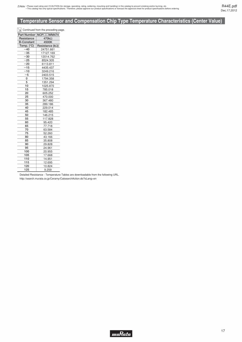
Temperature Sensor and Compensation Chip Type Temperature Characteristics (Center Value)
Continued from the preceding page.
Y40Y35Y30Y25Y20Y15Y10Y505101520253035404550556065707580859095100105110115120125
24751.66117127.16912014.7628524.3056113.8114435.4373249.2162403.5151794.3581351.2941025.870785.018605.252470.000367.480289.186229.014182.485146.215117.82895.42077.71863.58452.26043.16635.80829.82824.96120.95517.66814.95112.69510.8249.259
NCPppWM474
Resistance (kΩ)4500K470kΩ
Temp. (°C)B-ConstantResistance
Part Number
Detailed Resistance - Temperature Tables are downloadable from the following URL.
http://search.murata.co.jp/Ceramy/CatsearchAction.do?sLang=en
R44E.pdfDec.17,2012
17
!Note • Please read rating and !CAUTION (for storage, operating, rating, soldering, mounting and handling) in this catalog to prevent smoking and/or burning, etc.• This catalog has only typical specifi cations. Therefore, please approve our product specifi cations or transact the approval sheet for product specifi cations before ordering.
Temperature Sensor and Compensation Chip Type Temperature Characteristics (Center Value)
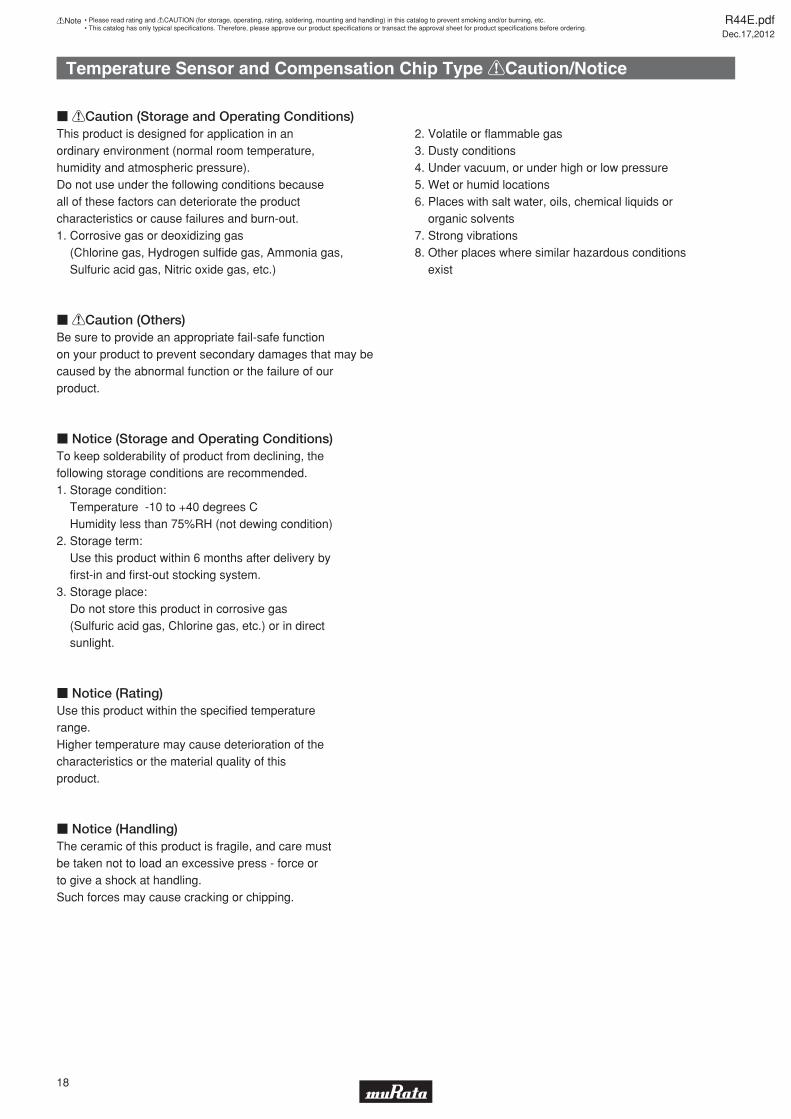
Temperature Sensor and Compensation Chip Type !Caution/Notice
c !Caution (Storage and Operating Conditions)This product is designed for application in an ordinary environment (normal room temperature, humidity and atmospheric pressure). Do not use under the following conditions because all of these factors can deteriorate the product characteristics or cause failures and burn-out.1. Corrosive gas or deoxidizing gas (Chlorine gas, Hydrogen sulfi de gas, Ammonia gas, Sulfuric acid gas, Nitric oxide gas, etc.)
2. Volatile or fl ammable gas3. Dusty conditions4. Under vacuum, or under high or low pressure5. Wet or humid locations6. Places with salt water, oils, chemical liquids or organic solvents7. Strong vibrations8. Other places where similar hazardous conditions exist
c !Caution (Others)Be sure to provide an appropriate fail-safe function on your product to prevent secondary damages that may be caused by the abnormal function or the failure of our product.
c Notice (Storage and Operating Conditions)
c Notice (Rating)Use this product within the specifi ed temperature range.Higher temperature may cause deterioration of the characteristics or the material quality of this product.
c Notice (Handling)The ceramic of this product is fragile, and care mustbe taken not to load an excessive press - force or to give a shock at handling. Such forces may cause cracking or chipping.
R44E.pdfDec.17,2012
18
!Note • Please read rating and !CAUTION (for storage, operating, rating, soldering, mounting and handling) in this catalog to prevent smoking and/or burning, etc.• This catalog has only typical specifi cations. Therefore, please approve our product specifi cations or transact the approval sheet for product specifi cations before ordering.
To keep solderability of product from declining, thefollowing storage conditions are recommended.1. Storage condition: Temperature -10 to +40 degrees C Humidity less than 75%RH (not dewing condition)2. Storage term: Use this product within 6 months after delivery by fi rst-in and fi rst-out stocking system.3. Storage place: Do not store this product in corrosive gas (Sulfuric acid gas, Chlorine gas, etc.) or in direct sunlight.
Temperature Sensor and Compensation Chip Type !Caution/Notice
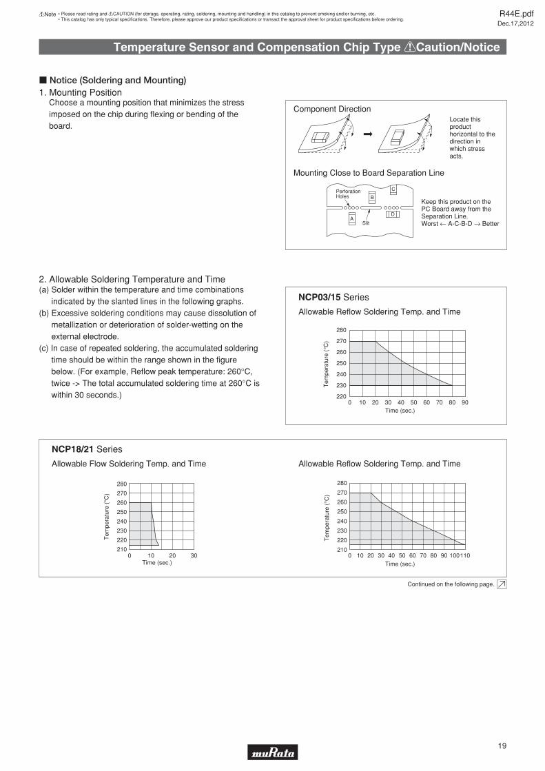
Locate this product horizontal to the direction in which stress acts.
Keep this product on the PC Board away from the Separation Line. Worst ← A-C-B-D → Better
Component Direction
Mounting Close to Board Separation Line
A
B
D
CPerforationHoles
Slit
1. Mounting Position
2. Allowable Soldering Temperature and Time
Choose a mounting position that minimizes the stress imposed on the chip during flexing or bending of the board.
(a) Solder within the temperature and time combinations indicated by the slanted lines in the following graphs.
(b) Excessive soldering conditions may cause dissolution of metallization or deterioration of solder-wetting on the external electrode.
(c) In case of repeated soldering, the accumulated soldering time should be within the range shown in the figure below. (For example, Reflow peak temperature: 260°C, twice -> The total accumulated soldering time at 260°C is within 30 seconds.)
Continued on the following page.
Allowable Reflow Soldering Temp. and Time
Allowable Reflow Soldering Temp. and Time
Time (sec.)
Tem
pera
ture
(°C
)
280
270
260
250
240
230
220
2100 10 20 30
Time (sec.)
Tem
pera
ture
(°C
)
280
270
260
250
240
230
220
2100 1109020 30 40 50 60 70 1008010
Time (sec.)
Tem
pera
ture
(°C
)280
270
260
250
240
230
2200 9020 30 40 50 60 70 8010
NCP03/15 Series
Allowable Flow Soldering Temp. and Time
NCP18/21 Series
c Notice (Soldering and Mounting)
R44E.pdfDec.17,2012
19
!Note • Please read rating and !CAUTION (for storage, operating, rating, soldering, mounting and handling) in this catalog to prevent smoking and/or burning, etc.• This catalog has only typical specifi cations. Therefore, please approve our product specifi cations or transact the approval sheet for product specifi cations before ordering.
Temperature Sensor and Compensation Chip Type !Caution/Notice
For removing the flux after soldering, observe the following points in order to avoid deterioration of the characteristics or any change of the external electrodes' quality.
occurrence of resonance in ultrasonic cleaning.
non-washed type flux.
your reference, we are using the solder paste below for any internal tests of this product.
We are using the solder paste below for any internal tests of this product.
Use rosin type flux in soldering process.
caused in the product characteristics and reliability.
(*Water-soluble flux can be defined as non rosin type flux including wash-type flux and non-wash-type flux.)
NCP03/15 NCP18/21
Continued from the preceding page.
After cleaning, promptly dry this product.
room temp. or less than
r
room temp. or less than
r Frequency of several
Solvent
Dipping Cleaning
Ultrasonic Cleaning
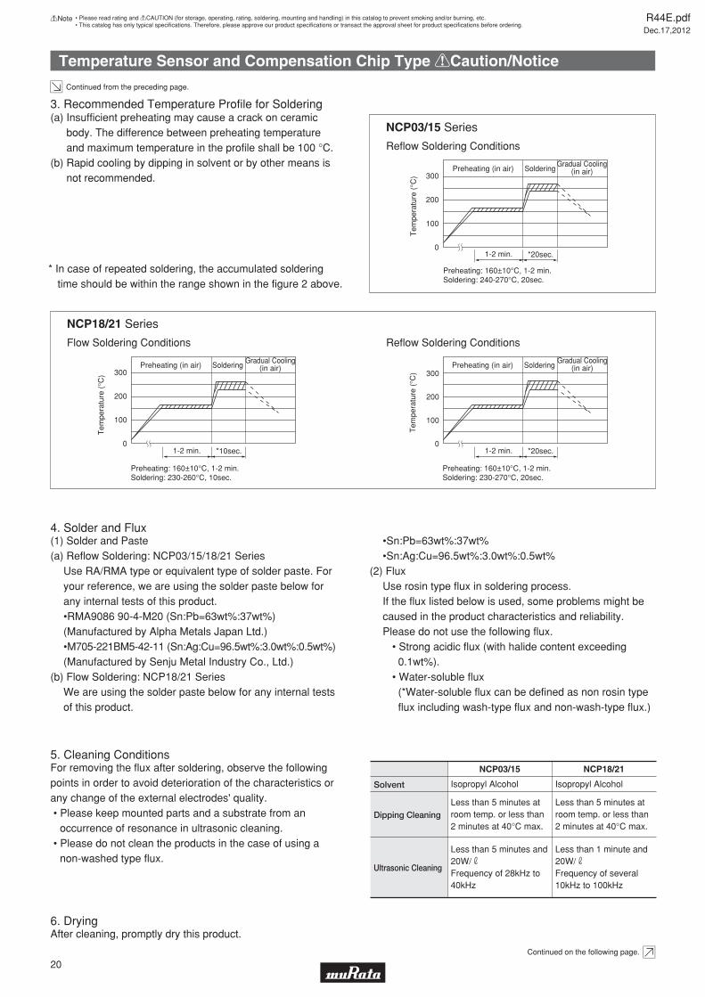
(b) Rapid cooling by dipping in solvent or by other means is not recommended.
Reflow Soldering Conditions
Reflow Soldering Conditions
SolderingGradual Cooling
(in air)
±
SolderingGradual Cooling
(in air)
±
SolderingGradual Cooling
(in air)
±
NCP03/15 Series
Flow Soldering Conditions
NCP18/21 Series
Continued on the following page.
R44E.pdfDec.17,2012
20
!Note • Please read rating and !CAUTION (for storage, operating, rating, soldering, mounting and handling) in this catalog to prevent smoking and/or burning, etc.• This catalog has only typical specifi cations. Therefore, please approve our product specifi cations or transact the approval sheet for product specifi cations before ordering.
Temperature Sensor and Compensation Chip Type !Caution/Notice
o Thin or insufficient adhesive may result in loose component contact with land during flow soldering.
o Low viscosity adhesive causes chips to slip after mounting.
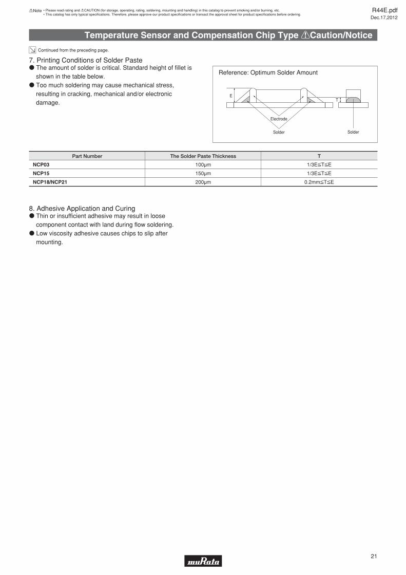
NCP03
NCP15
NCP18/NCP21
100μm
150μm
200μm
1/3EVTVE
1/3EVTVE
0.2mmVTVE
Part Number The Solder Paste Thickness T
Reference: Optimum Solder Amount
TE
Electrode
Solder Solder
Continued from the preceding page.
o The amount of solder is critical. Standard height of fillet is shown in the table below.
o Too much soldering may cause mechanical stress, resulting in cracking, mechanical and/or electronic damage.
7. Printing Conditions of Solder Paste
8. Adhesive Application and Curing
R44E.pdfDec.17,2012
21
!Note • Please read rating and !CAUTION (for storage, operating, rating, soldering, mounting and handling) in this catalog to prevent smoking and/or burning, etc.• This catalog has only typical specifi cations. Therefore, please approve our product specifi cations or transact the approval sheet for product specifi cations before ordering.
Temperature Sensor and Compensation Chip Type Package
NCP03
NCP15
NCP18
NCP21
15,000
10,000
4,000
-
-
4,000
Part NumberPaper Tape
Quantity (pcs.)
Embossed Tape
(in mm)
(in mm)
40 min.190-250
Vacant Section
210-250
Top Tape aloneCover Tape alone
Leader Unit
Trailer Unit
Chip-mounting Unit
Direction of Feed
ø180
ø21.0±0.8
ø13.0±0.2
ø60
2.0±0.5
9.013.0±1.0
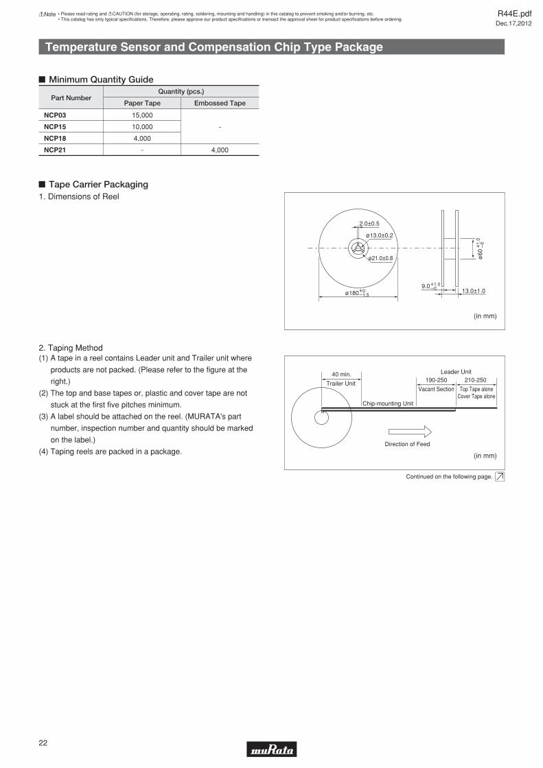
(1) A tape in a reel contains Leader unit and Trailer unit where
products are not packed. (Please refer to the figure at the
right.)
(2) The top and base tapes or, plastic and cover tape are not
stuck at the first five pitches minimum.
(3) A label should be attached on the reel. (MURATA's part
number, inspection number and quantity should be marked
on the label.)
(4) Taping reels are packed in a package.
1. Dimensions of Reel
2. Taping Method
Tape Carrier Packaging
Minimum Quantity Guide
Continued on the following page.
W0Y1.5
W1.0Y0
W1.
0Y
0
R44E.pdfDec.17,2012
22
!Note • Please read rating and !CAUTION (for storage, operating, rating, soldering, mounting and handling) in this catalog to prevent smoking and/or burning, etc.• This catalog has only typical specifi cations. Therefore, please approve our product specifi cations or transact the approval sheet for product specifi cations before ordering.
Temperature Sensor and Compensation Chip Type Package
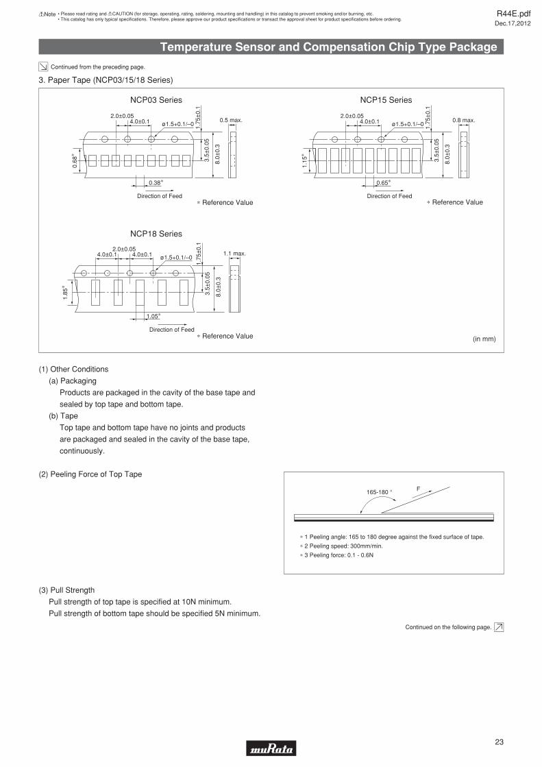
(1) Other Conditions
(a) Packaging
Products are packaged in the cavity of the base tape and
sealed by top tape and bottom tape.
(b) Tape
Top tape and bottom tape have no joints and products
are packaged and sealed in the cavity of the base tape,
continuously.
(2) Peeling Force of Top Tape
(3) Pull Strength
Pull strength of top tape is specified at 10N minimum.
Pull strength of bottom tape should be specified 5N minimum.
3. Paper Tape (NCP03/15/18 Series)
NCP15 Series
NCP18 Series
1.1 max.4.0±0.1 4.0±0.12.0±0.05
ø1.5+0.1/–0
1.75
±0.
1
3.5±
0.05
8.0±
0.3
Direction of Feed
1.05∗
0.8 max.4.0±0.12.0±0.05
ø1.5+0.1/–0 1.75
±0.
1
3.5±
0.05
1.15
∗
8.0±
0.3
Direction of Feed
0.65∗
(in mm)∗ Reference Value
∗ Reference Value
165-180 ° F
∗ 1 Peeling angle: 165 to 180 degree against the fixed surface of tape.
∗ 2 Peeling speed: 300mm/min.
∗ 3 Peeling force: 0.1 - 0.6N
Continued on the following page.
Continued from the preceding page.1.
85∗
∗ Reference Value
NCP03 Series
0.5 max.4.0±0.12.0±0.05
ø1.5+0.1/–0 1.75
±0.
1
3.5±
0.05
0.68
∗
8.0±
0.3
Direction of Feed
0.38∗
R44E.pdfDec.17,2012
23
!Note • Please read rating and !CAUTION (for storage, operating, rating, soldering, mounting and handling) in this catalog to prevent smoking and/or burning, etc.• This catalog has only typical specifi cations. Therefore, please approve our product specifi cations or transact the approval sheet for product specifi cations before ordering.
Temperature Sensor and Compensation Chip Type Package
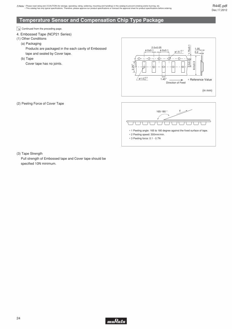
∗ 1 Peeling angle: 165 to 180 degree against the fixed surface of tape.
∗ 2 Peeling speed: 300mm/min.
∗ 3 Peeling force: 0.1 - 0.7N
F165-180 °
Continued from the preceding page.
(2) Peeling Force of Cover Tape
(3) Tape Strength
Pull strength of Embossed tape and Cover tape should be
specified 10N minimum.
(1) Other Conditions
(a) Packaging
Products are packaged in the each cavity of Embossed
tape and sealed by Cover tape.
(b) Tape
Cover tape has no joints.
4. Embossed Tape (NCP21 Series)
1.050.2
4.0±0.12.0±0.05
4.0±0.1 ø1.5
1.75
±0.
1
ø1.0 1.45∗ ∗ Reference Value
3.5±
0.05
8.0±
0.3
Direction of Feed
2.25
∗
(in mm)
+0.3-0
+0.1-1
R44E.pdfDec.17,2012
24
!Note • Please read rating and !CAUTION (for storage, operating, rating, soldering, mounting and handling) in this catalog to prevent smoking and/or burning, etc.• This catalog has only typical specifi cations. Therefore, please approve our product specifi cations or transact the approval sheet for product specifi cations before ordering.
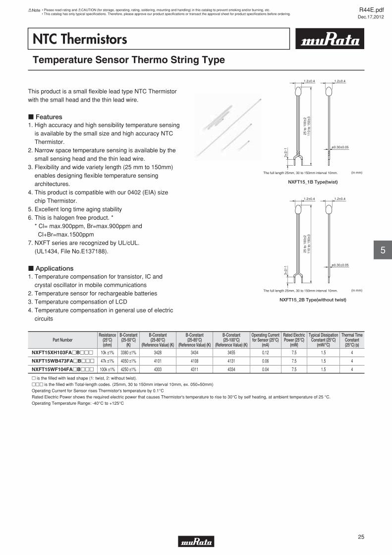
NTC ThermistorsTemperature Sensor Thermo String Type
This product is a small fl exible lead type NTC Thermistor with the small head and the thin lead wire.
c Features1. High accuracy and high sensibility temperature sensing is available by the small size and high accuracy NTC Thermistor.2. Narrow space temperature sensing is available by the small sensing head and the thin lead wire.3. Flexibility and wide variety length (25 mm to 150mm) enables designing fl exible temperature sensing architectures. 4. This product is compatible with our 0402 (EIA) size chip Thermistor.5. Excellent long time aging stability6. This is halogen free product. * * Cl= max.900ppm, Br=max.900ppm and Cl+Br=max.1500ppm7. NXFT series are recognized by UL/cUL. (UL1434, File No.E137188).
c Applications1. Temperature compensation for transistor, IC and crystal oscillator in mobile communications2. Temperature sensor for rechargeable batteries3. Temperature compensation of LCD4. Temperature compensation in general use of electric circuits
1.2±0.4
25 to
100
±2
110
to 1
50±
3
3+2/
-1
1.2±0.4
ø0.30±0.05
The full length 25mm, 30 to 150mm interval 10mm. (in mm)
1.2±0.4
25 to
100
±2
110
to 1
50±
3
3+2/
-1
1.2±0.4
ø0.30±0.05
The full length 25mm, 30 to 150mm interval 10mm. (in mm)
Part NumberResistance
(25°C)(ohm)
B-Constant(25-50°C)
(K)
B-Constant(25-80°C)
(Reference Value) (K)
B-Constant(25-85°C)
(Reference Value) (K)
B-Constant(25-100°C)
(Reference Value) (K)
Operating Currentfor Sensor (25°C)
(mA)
Rated ElectricPower (25°C)
(mW)
Typical DissipationConstant (25°C)
(mW/°C)
Thermal TimeConstant(25°C) (s)
NXFT15XH103FApBppp 10k ±1% 3380 ±1% 3428 3434 3455 0.12 7.5 1.5 4
NXFT15WB473FApBppp 47k ±1% 4050 ±1% 4101 4108 4131 0.06 7.5 1.5 4
NXFT15WF104FApBppp 100k ±1% 4250 ±1% 4303 4311 4334 0.04 7.5 1.5 4
p is the fi lled with lead shape (1: twist, 2: without twist).
ppp is the fi lled with Total-length codes. (25mm, 30 to 150mm interval 10mm, ex. 050=50mm)
Operating Current for Sensor rises Thermistor's temperature by 0.1°C
Rated Electric Power shows the required electric power that causes Thermistor's temperature to rise to 30°C by self heating, at ambient temperature of 25 °C.
Operating Temperature Range: -40°C to +125°C
R44E.pdfDec.17,2012
25
!Note • Please read rating and !CAUTION (for storage, operating, rating, soldering, mounting and handling) in this catalog to prevent smoking and/or burning, etc.• This catalog has only typical specifi cations. Therefore, please approve our product specifi cations or transact the approval sheet for product specifi cations before ordering.
5
NXFT15_1B Type(twist)
NXFT15_2B Type(without twist)
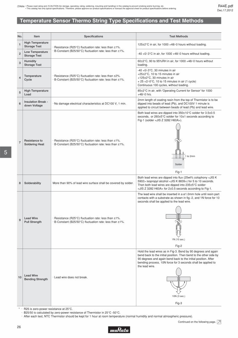
Temperature Sensor Thermo String Type Specifi cations and Test Methods
Hold the lead wires as in Fig-3. Bend by 90 degrees and again bend back to the initial position. Then bend to the other side by 90 degrees and again bend back to the initial position. After bending process, 10N force for 3 seconds shall be applied to the lead wire.
Fig-3
10Lead WireBending Strength
· Lead wire does not break.
Continued on the following page.
The lead wire shall be inserted in a ø1.0mm hole until resin part contacts with a substrate as shown in fig.-2, and 1N force for 10 seconds shall be applied to the lead wire.
Fig-2
9Lead WirePull Strength
· Resistance (R25°C) fluctuation rate: less than ±1%.· B-Constant (B25/50°C) fluctuation rate: less than ±1%.
Both lead wires are dipped into flux (25wt% colophony <JIS K 5902> isopropyl alcohol <JIS K 8839>) for 5 to 10 seconds. Then both lead wires are dipped into 235±5°C solder <JIS Z 3282 H60A> for 2±0.5 seconds according to Fig-1.
8 Solderability More than 90% of lead wire surface shall be covered by solder.
Both lead wires are dipped into 350±10°C solder for 3.5±0.5 seconds, or 260±5°C solder for 10±1 seconds according to Fig-1 (solder <JIS Z 3282 H60A>).
Fig-1
7Resistance toSoldering Heat
· Resistance (R25°C) fluctuation rate: less than ±1%.· B-Constant (B25/50°C) fluctuation rate: less than ±1%.
2mm length of coating resin from the top of Thermistor is to be dipped into beads of lead (Pb), and DC100V 1 minute is applied to circuit between beads of lead (Pb) and lead wire.
6Insulation Break -down Voltage
· No damage electrical characteristics at DC100 V, 1 min.
85±2°C in air, with 'Operating Current for Sensor' for 1000 +48/-0 hrs.
5High TemperatureLoad
-40 +0/-3°C, 30 minutes in air+25±2°C, 10 to 15 minutes in air+125±2°C, 30 minutes in air + 25 +2/-0°C, 10 to 15 minutes in air (1 cycle)Continuous 100 cycles, without loading.
4Temperature Cycle
60±2°C, 90 to 95%RH in air, for 1000 +48/-0 hours without loading.
3HumidityStorage Test
· Resistance (R25°C) fluctuation rate: less than ±2%.· B-Constant (B25/50°C) fluctuation rate: less than ±1%.
-40 +0/-3°C in air, for 1000 +48/-0 hours without loading.2Low TemperatureStorage Test
125±2°C in air, for 1000 +48/-0 hours without loading.1High TemperatureStorage Test · Resistance (R25°C) fluctuation rate: less than ±1%.
· B-Constant (B25/50°C) fluctuation rate: less than ±1%.
No. Test MethodsSpecificationsItem
* · R25 is zero-power resistance at 25°C. · B25/50 is calculated by zero-power resistance of Thermistor in 25°C -50°C. · After each test, NTC Thermistor should be kept for 1 hour at room temperature (normal humidity and normal atmospheric pressure).
Solder
1 to 2mm
1N (10 sec.)
10N (3 sec.)
R44E.pdfDec.17,2012
26
!Note • Please read rating and !CAUTION (for storage, operating, rating, soldering, mounting and handling) in this catalog to prevent smoking and/or burning, etc.• This catalog has only typical specifi cations. Therefore, please approve our product specifi cations or transact the approval sheet for product specifi cations before ordering.
5
Temperature Sensor Thermo String Type Specifi cations and Test Methods
Continued from the preceding page.
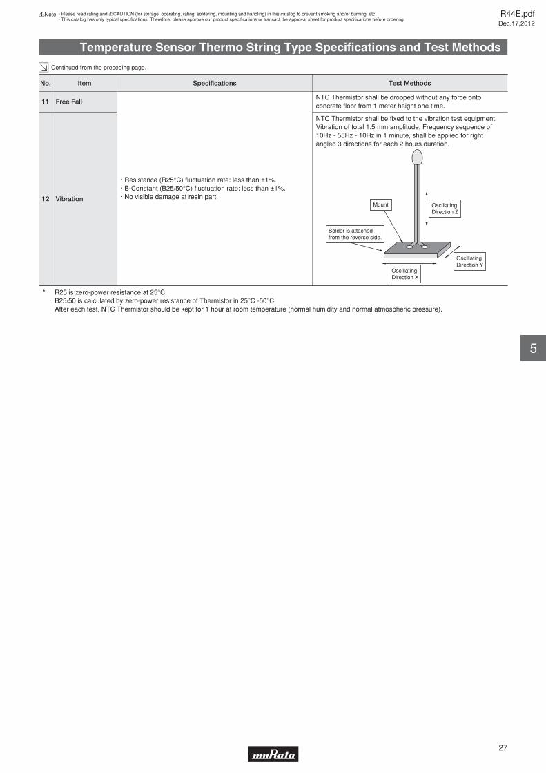
NTC Thermistor shall be fixed to the vibration test equipment. Vibration of total 1.5 mm amplitude, Frequency sequence of 10Hz - 55Hz - 10Hz in 1 minute, shall be applied for right angled 3 directions for each 2 hours duration.
12 Vibration
NTC Thermistor shall be dropped without any force onto concrete floor from 1 meter height one time.
11 Free Fall
· Resistance (R25°C) fluctuation rate: less than ±1%.· B-Constant (B25/50°C) fluctuation rate: less than ±1%.· No visible damage at resin part.
* · R25 is zero-power resistance at 25°C. · B25/50 is calculated by zero-power resistance of Thermistor in 25°C -50°C. · After each test, NTC Thermistor should be kept for 1 hour at room temperature (normal humidity and normal atmospheric pressure).
No. Test MethodsSpecificationsItem
Mount
Solder is attached from the reverse side.
OscillatingDirection Z
Oscillating Direction X
OscillatingDirection Y
R44E.pdfDec.17,2012
27
!Note • Please read rating and !CAUTION (for storage, operating, rating, soldering, mounting and handling) in this catalog to prevent smoking and/or burning, etc.• This catalog has only typical specifi cations. Therefore, please approve our product specifi cations or transact the approval sheet for product specifi cations before ordering.
5
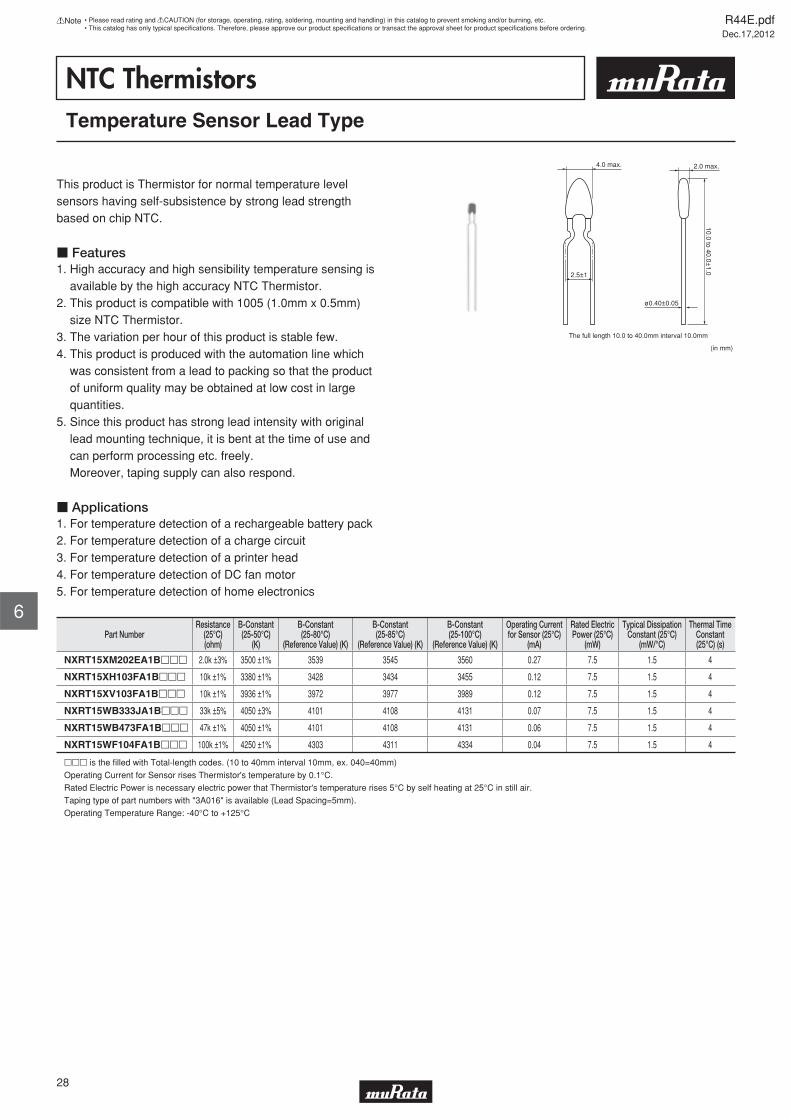
NTC ThermistorsTemperature Sensor Lead Type
This product is Thermistor for normal temperature level sensors having self-subsistence by strong lead strength based on chip NTC.
c Features1. High accuracy and high sensibility temperature sensing is available by the high accuracy NTC Thermistor.2. This product is compatible with 1005 (1.0mm x 0.5mm) size NTC Thermistor.3. The variation per hour of this product is stable few.4. This product is produced with the automation line which was consistent from a lead to packing so that the product of uniform quality may be obtained at low cost in large quantities.5. Since this product has strong lead intensity with original lead mounting technique, it is bent at the time of use and can perform processing etc. freely. Moreover, taping supply can also respond.
c Applications1. For temperature detection of a rechargeable battery pack2. For temperature detection of a charge circuit3. For temperature detection of a printer head4. For temperature detection of DC fan motor5. For temperature detection of home electronics
(in mm)
10.0 to 40.0±1.0
4.0 max.
2.5±1
The full length 10.0 to 40.0mm interval 10.0mm
2.0 max.
ø0.40±0.05
Part NumberResistance
(25°C)(ohm)
B-Constant(25-50°C)
(K)
B-Constant(25-80°C)
(Reference Value) (K)
B-Constant(25-85°C)
(Reference Value) (K)
B-Constant(25-100°C)
(Reference Value) (K)
Operating Currentfor Sensor (25°C)
(mA)
Rated ElectricPower (25°C)
(mW)
Typical DissipationConstant (25°C)
(mW/°C)
Thermal TimeConstant(25°C) (s)
NXRT15XM202EA1Bppp 2.0k ±3% 3500 ±1% 3539 3545 3560 0.27 7.5 1.5 4
NXRT15XH103FA1Bppp 10k ±1% 3380 ±1% 3428 3434 3455 0.12 7.5 1.5 4
NXRT15XV103FA1Bppp 10k ±1% 3936 ±1% 3972 3977 3989 0.12 7.5 1.5 4
NXRT15WB333JA1Bppp 33k ±5% 4050 ±3% 4101 4108 4131 0.07 7.5 1.5 4
NXRT15WB473FA1Bppp 47k ±1% 4050 ±1% 4101 4108 4131 0.06 7.5 1.5 4
NXRT15WF104FA1Bppp 100k ±1% 4250 ±1% 4303 4311 4334 0.04 7.5 1.5 4
ppp is the fi lled with Total-length codes. (10 to 40mm interval 10mm, ex. 040=40mm)
Operating Current for Sensor rises Thermistor's temperature by 0.1°C.
Rated Electric Power is necessary electric power that Thermistor's temperature rises 5°C by self heating at 25°C in still air.
Taping type of part numbers with "3A016" is available (Lead Spacing=5mm).
Operating Temperature Range: -40°C to +125°C
R44E.pdfDec.17,2012
28
!Note • Please read rating and !CAUTION (for storage, operating, rating, soldering, mounting and handling) in this catalog to prevent smoking and/or burning, etc.• This catalog has only typical specifi cations. Therefore, please approve our product specifi cations or transact the approval sheet for product specifi cations before ordering.
6
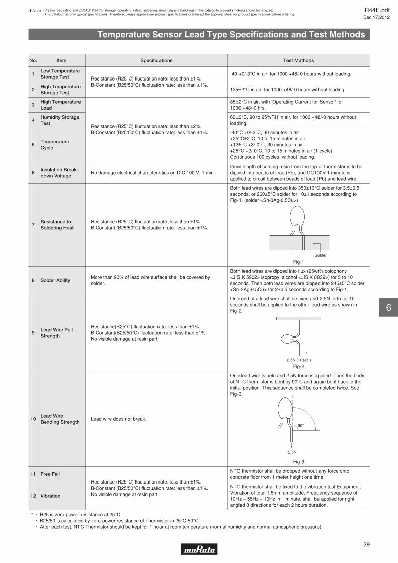
Temperature Sensor Lead Type Specifi cations and Test Methods
NTC thermistor shall be fixed to the vibration test Equipment. Vibration of total 1.5mm amplitude, Frequency sequence of 10Hz – 55Hz – 10Hz in 1 minute, shall be applied for right angled 3 directions for each 2 hours duration.
12 Vibration
NTC thermistor shall be dropped without any force onto concrete floor from 1 meter height one time.
11 Free Fall
· Resistance (R25°C) fluctuation rate: less than ±1%.· B-Constant (B25/50°C) fluctuation rate: less than ±1%.· No visible damage at resin part.
* · R25 is zero-power resistance at 25°C. · B25/50 is calculated by zero-power resistance of Thermistor in 25°C-50°C. · After each test, NTC Thermistor should be kept for 1 hour at room temperature (normal humidity and normal atmospheric pressure).
One lead wire is held and 2.5N force is applied. Then the body of NTC thermistor is bent by 90°C and again bent back to the initial position. This sequence shall be completed twice. See Fig-3.
Fig-3
10Lead Wire Bending Strength
· Lead wire does not break.
One end of a lead wire shall be fixed and 2.5N forth for 10 seconds shall be applied to the other lead wire as shown in Fig-2.
Fig-2
9Lead Wire Pull Strength
· Resistance(R25°C) fluctuation rate: less than ±1%.· B-Constant(B25/50°C) fluctuation rate: less than ±1%.· No visible damage at resin part.
Both lead wires are dipped into flux (25wt% colophony <JIS K 5902> isopropyl alcohol <JIS K 8839>) for 5 to 10 seconds. Then both lead wires are dipped into 245±5°C solder <Sn-3Ag-0.5Cu> for 2±0.5 seconds according to Fig-1.
8 Solder Ability· More than 90% of lead wire surface shall be covered by solder.
Both lead wires are dipped into 350±10°C solder for 3.5±0.5 seconds, or 260±5°C solder for 10±1 seconds according to Fig-1. (solder <Sn-3Ag-0.5Cu>)
Fig-1
7Resistance to Soldering Heat
· Resistance (R25°C) fluctuation rate: less than ±1%.· B-Constant (B25/50°C) fluctuation rate: less than ±1%.
2mm length of coating resin from the top of thermistor is to be dipped into beads of lead (Pb), and DC100V 1 minute is applied to circuit between beads of lead (Pb) and lead wire.
6Insulation Break - down Voltage
· No damage electrical characteristics on D.C.100 V, 1 min.
-40°C +0/-3°C, 30 minutes in air+25°C±2°C, 10 to 15 minutes in air+125°C +3/-0°C, 30 minutes in air+25°C +2/-0°C, 10 to 15 minutes in air (1 cycle)Continuous 100 cycles, without loading.
5Temperature Cycle
60±2°C, 90 to 95%RH in air, for 1000 +48/-0 hours without loading.
4Humidity Storage Test
85±2°C in air, with ‘Operating Current for Sensor’ for 1000 +48/-0 hrs.
3High Temperature Load
· Resistance (R25°C) fluctuation rate: less than ±2%.· B-Constant (B25/50°C) fluctuation rate: less than ±1%.
125±2°C in air, for 1000 +48/-0 hours without loading.2High Temperature Storage Test
-40 +0/-3°C in air, for 1000 +48/-0 hours without loading.1Low Temperature Storage Test · Resistance (R25°C) fluctuation rate: less than ±1%.
· B-Constant (B25/50°C) fluctuation rate: less than ±1%.
No. Test MethodsSpecificationsItem
Solder
2.5N (10sec.)
2.5N
90°
R44E.pdfDec.17,2012
29
!Note • Please read rating and !CAUTION (for storage, operating, rating, soldering, mounting and handling) in this catalog to prevent smoking and/or burning, etc.• This catalog has only typical specifi cations. Therefore, please approve our product specifi cations or transact the approval sheet for product specifi cations before ordering.
6

R44E.pdfDec.17,2012
30
!Note • Please read rating and !CAUTION (for storage, operating, rating, soldering, mounting and handling) in this catalog to prevent smoking and/or burning, etc.• This catalog has only typical specifi cations. Therefore, please approve our product specifi cations or transact the approval sheet for product specifi cations before ordering.
Temperature Sensor Thermo String/Lead Type Temperature Characteristics (Center Value)
Y40Y35Y30Y25Y20Y15Y10Y505101520253035404550556065707580859095100105110115120125
44.98133.67125.44419.41714.95511.6199.0977.1785.7074.5683.6822.9862.4372.0001.6511.3701.1430.9580.8070.6820.5800.4950.4240.3650.3150.2730.2370.2070.1810.1600.1410.1240.1100.098
NXRT15XM202
Resistance (kΩ)Temp. (°C)B-ConstantResistance
Part Number
195.652148.171113.34787.55968.23753.65042.50633.89227.21922.02117.92614.67412.08110.0008.3156.9485.8344.9174.1613.5353.0142.5862.2281.9251.6691.4521.2681.1100.9740.8580.7580.6720.5960.531
NXRT15XH103
Resistance (kΩ)337.503243.332177.496130.85997.42873.23055.52942.46732.74725.45019.93215.72712.49810.0008.0546.5295.3244.3663.6012.9852.4882.0831.7521.4801.2561.0700.9160.7870.6790.5880.5120.4460.3910.343
NXRT15XV103
Resistance (kΩ)3500K 3380K 3936K2.0kΩ 10kΩ 10kΩ
1227.263874.449630.851460.457339.797253.363190.766144.964111.08785.84266.86152.47041.47133.00026.43021.29817.26614.07611.5389.5067.8706.5495.4754.5953.8743.2822.7892.3792.0381.7511.5091.3061.1340.987
NXRT15WB333
Resistance (kΩ)4050K33kΩ
1747.9201245.428898.485655.802483.954360.850271.697206.463158.214122.25995.22774.73059.06547.00037.64330.33424.59120.04816.43313.53911.2099.3287.7986.5445.5184.6743.9723.3882.9022.4942.1501.8601.6151.406
NXRT15WB473
Resistance (kΩ)4050K47kΩ
4397.1193088.5992197.2251581.8811151.037846.579628.988471.632357.012272.500209.710162.651127.080100.00079.22263.16750.67740.90433.19527.09122.22418.32315.18412.63510.5668.8737.4816.3375.3844.5943.9343.3802.9162.522
NXRT15WF104
Resistance (kΩ)4250K100kΩ
Detailed Resistance - Temperature Tables are downloadable from the following URL.
http://search.murata.co.jp/Ceramy/CatsearchAction.do?sLang=en
Y40Y35Y30Y25Y20Y15Y10Y505101520253035404550556065707580859095100105110115120125
197.388149.395114.34588.38168.91554.16642.88934.19627.44522.16518.01014.72012.09910.0008.3096.9395.8244.9114.1603.5393.0242.5932.2331.9291.6731.4551.2701.1120.9760.8600.7590.6730.5980.532
NXFT15XH103
Resistance (kΩ)Temp. (°C)B-ConstantResistance
Part Number
1690.5901215.320882.908647.911480.069359.009270.868206.113158.126122.26795.25674.75459.07547.00037.63630.32624.58320.04316.43313.54511.2239.3457.8186.5715.5484.7044.0043.4222.9362.5282.1841.8931.6461.436
NXFT15WB473
Resistance (kΩ)4221.2802995.0402147.0001554.6001136.690839.019624.987469.678355.975272.011209.489162.559127.057100.00079.22263.16750.67740.90433.19527.09122.22418.32315.18412.63510.5668.8737.4816.3375.3844.5943.9343.3802.9162.522
NXFT15WF104
Resistance (kΩ)3380K 4050K 4250K10kΩ 47kΩ 100kΩ
Temperature Sensor Thermo String/Lead Type !Caution/Notice
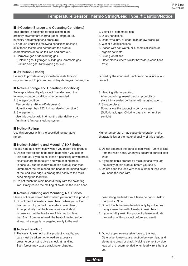
c !Caution (Storage and Operating Conditions)This product is designed for application in an ordinary environment (normal room temperature, humidity and atmospheric pressure). Do not use under the following conditions because all of these factors can deteriorate the product characteristics or cause failures and burn-out.1. Corrosive gas or deoxidizing gas (Chlorine gas, Hydrogen sulfi de gas, Ammonia gas, Sulfuric acid gas, Nitric oxide gas, etc.)
2. Volatile or fl ammable gas3. Dusty conditions4. Under vacuum, or under high or low pressure5. Wet or humid locations6. Places with salt water, oils, chemical liquids or organic solvents7. Strong vibrations8. Other places where similar hazardous conditions exist
c !Caution (Others)
c Notice (Storage and Operating Conditions)To keep solderability of product from declining, thefollowing storage condition is recommended.1. Storage condition: Temperature -10 to +40 degrees C Humidity less than 75%RH (not dewing condition)2. Storage term: Use this product within 6 months after delivery by fi rst-in and fi rst-out stocking system.
3. Handling after unpacking: After unpacking, reseal product promptly or store it in a sealed container with a drying agent.4. Storage place: Do not store this product in corrosive gas (Sulfuric acid gas, Chlorine gas, etc.) or in direct sunlight.
c Notice (Rating)
c Notice (Soldering and Mounting) NXF Series
R44E.pdfDec.17,2012
31
!Note • Please read rating and !CAUTION (for storage, operating, rating, soldering, mounting and handling) in this catalog to prevent smoking and/or burning, etc.• This catalog has only typical specifi cations. Therefore, please approve our product specifi cations or transact the approval sheet for product specifi cations before ordering.
Be sure to provide an appropriate fail-safe function on your product to prevent secondary damages that may be
caused by the abnormal function or the failure of our product.
Use this product within the specifi ed temperature range.
Higher temperature may cause deterioration of the characteristics or the material quality of this product.
Please note as shown below when you mount this product.1. Do not melt solder in the resin head when you solder this product. If you do so, it has a possibility of wire break, electric short mode failure and wire coating break. In case you cut the lead wire of this product less than 20mm from the resin head, the heat of the melted solder at the lead wire edge is propagated easily to the resin head along the lead wire.2. Do not touch the resin head directly with the soldering iron. It may cause the melting of solder in the resin head.
3. Do not separate the parallel lead wires 10mm or less from the resin head, when you separate parallel lead wires.4. If you mold this product by resin, please evaluate the quality of this product before you use it.5. Do not bend the lead wire radius 1mm or less when you bend the lead wire.
c Notice (Soldering and Mounting) NXR SeriesPlease notice as shown below when you mount this product.1. Do not melt the solder in resin head, when you solder this product. If you melt the solder in resin head, it has posibility that the break of wire and short. In case you cut the lead wire of this product less than 8mm from resin head, the heat of melted solder at lead wire edge is propagated easily to the resin
head along the lead wire. Please do not cut below this product 9mm.2. Do not touch the resin head directly by solder iron. It may cause the melt of solder in resin head.3. If you mold by resin this product, please evaluate the qualityl of this product before you use it.
c Notice (Handling)1. The ceramic element of this product is fragile, and care must be taken not to load an excessive press-force or not to give a shock at handling. Such forces may cause cracking or chipping.
2. Do not apply an excessive force to the lead. Otherwise, it may cause junction between lead and element to break or crack. Holding element by side lead wire is recommended when lead wire is bent or cut.
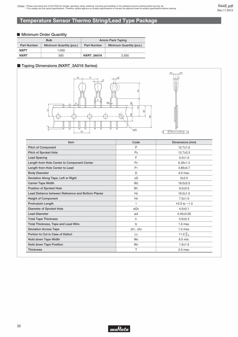
Temperature Sensor Thermo String/Lead Type Package
Minimum Order Quantity
Part Number
Bulk
Minimum Quantity (pcs.)
-1,000
2,500500
Part Number
Ammo Pack Taping
Minimum Quantity (pcs.)
NXFT
NXRT
-
NXRT_3A016
P
L3
W3
W1
W0
W2
H0
H3
D
ød
ΔS T
Δh2Δh1
I
t1
P1
P2
F
øD0P0 t2
Item
Pitch of Component
Pitch of Sproket Hole
Lead Spacing
Length from Hole Center to Component Center
Length from Hole Center to Lead
Body Diameter
Deviation Along Tape, Left or Right
Carrier Tape Width
Position of Sproket Hole
Lead Distance between Reference and Bottom Planes
Height of Component
Protrusioin Length
Diameter of Sproket Hole
Lead Diameter
Total Tape Thickness
Total Thickness, Tape and Lead Wire
Deviation Across Tape
Portion to Cut in Case of Defect
Hold down Tape Width
Hold down Tape Position
Thickness
P
P0
F
P2
P1
D
S
W3
W1
H0
H3
l
øD0
ød
t1
t2
h1, h2
L3
W0
W2
T
12.7±1.0
12.7±0.3
5.0±1.0
6.35±1.3
3.85±0.7
4.0 max.
0±2.0
18.0±0.5
9.0±0.5
16.0±1.0
7.5±1.0
W0.5 to Y1.0
4.0±0.1
0.40±0.05
0.6±0.3
1.6 max.
1.0 max.
11.0
9.5 min.
1.5±1.5
2.0 max.
Dimensions (mm)Code
+0–2.0
c Taping Dimensions (NXRT_3A016 Series)
R44E.pdfDec.17,2012
32
!Note • Please read rating and !CAUTION (for storage, operating, rating, soldering, mounting and handling) in this catalog to prevent smoking and/or burning, etc.• This catalog has only typical specifi cations. Therefore, please approve our product specifi cations or transact the approval sheet for product specifi cations before ordering.
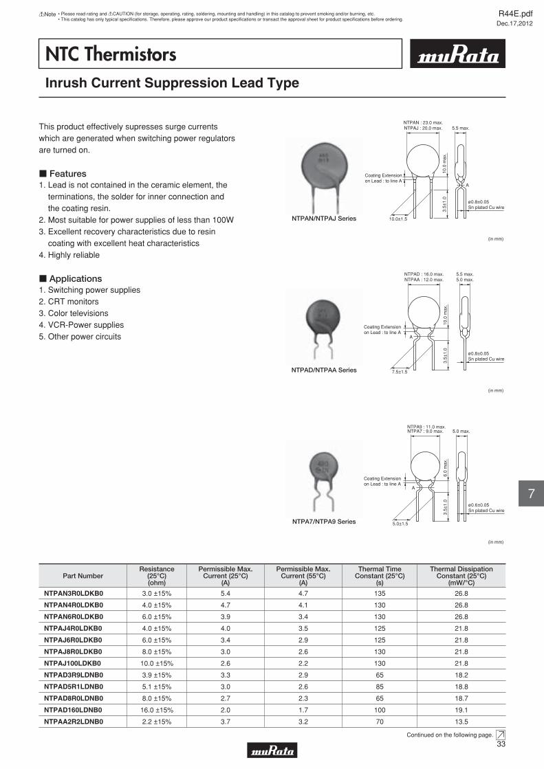
NTC ThermistorsInrush Current Suppression Lead Type
This product effectively supresses surge currents which are generated when switching power regulators are turned on.
c Features1. Lead is not contained in the ceramic element, the terminations, the solder for inner connection and the coating resin.2. Most suitable for power supplies of less than 100W3. Excellent recovery characteristics due to resin coating with excellent heat characteristics4. Highly reliable
c Applications1. Switching power supplies2. CRT monitors 3. Color televisions4. VCR-Power supplies 5. Other power circuits
Coating Extensionon Lead : to line A
10.0
max
.3.
5±1.
0
NTPAN : 23.0 max.NTPAJ : 20.0 max. 5.5 max.
10.0±1.5
ø0.8±0.05Sn plated Cu wire
A
(in mm)
NTPAN/NTPAJ Series
Coating Extensionon Lead : to line A
10.0
max
.3.
5±1.
0
NTPAD : 16.0 max.NTPAA : 12.0 max.
5.5 max.5.0 max.
7.5±1.5
ø0.8±0.05Sn plated Cu wire
A
(in mm)
NTPAD/NTPAA Series
Coating Extensionon Lead : to line A
6.0
max
.3.
5±1.
0
NTPA7 : 9.0 max.NTPA9 : 11.0 max.
5.0 max.
5.0±1.5
ø0.6±0.05Sn plated Cu wire
A
(in mm)
NTPA7/NTPA9 Series
Part NumberResistance
(25°C)(ohm)
Permissible Max.Current (25°C)
(A)
Permissible Max.Current (55°C)
(A)
Thermal TimeConstant (25°C)
(s)
Thermal DissipationConstant (25°C)
(mW/°C)
NTPAN3R0LDKB0 3.0 ±15% 5.4 4.7 135 26.8
NTPAN4R0LDKB0 4.0 ±15% 4.7 4.1 130 26.8
NTPAN6R0LDKB0 6.0 ±15% 3.9 3.4 130 26.8
NTPAJ4R0LDKB0 4.0 ±15% 4.0 3.5 125 21.8
NTPAJ6R0LDKB0 6.0 ±15% 3.4 2.9 125 21.8
NTPAJ8R0LDKB0 8.0 ±15% 3.0 2.6 130 21.8
NTPAJ100LDKB0 10.0 ±15% 2.6 2.2 130 21.8
NTPAD3R9LDNB0 3.9 ±15% 3.3 2.9 65 18.2
NTPAD5R1LDNB0 5.1 ±15% 3.0 2.6 85 18.8
NTPAD8R0LDNB0 8.0 ±15% 2.7 2.3 65 18.7
NTPAD160LDNB0 16.0 ±15% 2.0 1.7 100 19.1
NTPAA2R2LDNB0 2.2 ±15% 3.7 3.2 70 13.5
Continued on the following page.
R44E.pdfDec.17,2012
33
!Note • Please read rating and !CAUTION (for storage, operating, rating, soldering, mounting and handling) in this catalog to prevent smoking and/or burning, etc.• This catalog has only typical specifi cations. Therefore, please approve our product specifi cations or transact the approval sheet for product specifi cations before ordering.
7
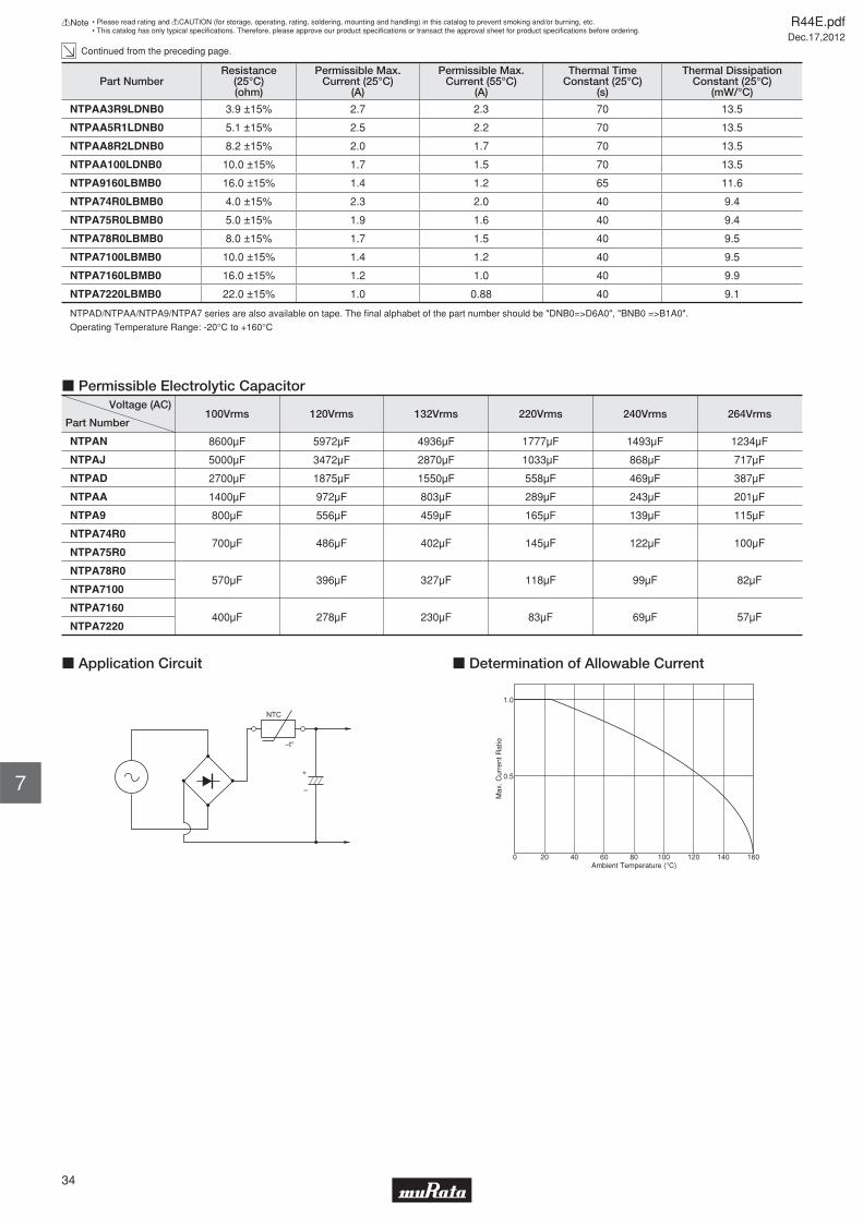
Continued from the preceding page.
Part NumberResistance
(25°C)(ohm)
Permissible Max.Current (25°C)
(A)
Permissible Max.Current (55°C)
(A)
Thermal TimeConstant (25°C)
(s)
Thermal DissipationConstant (25°C)
(mW/°C)
NTPAA3R9LDNB0 3.9 ±15% 2.7 2.3 70 13.5
NTPAA5R1LDNB0 5.1 ±15% 2.5 2.2 70 13.5
NTPAA8R2LDNB0 8.2 ±15% 2.0 1.7 70 13.5
NTPAA100LDNB0 10.0 ±15% 1.7 1.5 70 13.5
NTPA9160LBMB0 16.0 ±15% 1.4 1.2 65 11.6
NTPA74R0LBMB0 4.0 ±15% 2.3 2.0 40 9.4
NTPA75R0LBMB0 5.0 ±15% 1.9 1.6 40 9.4
NTPA78R0LBMB0 8.0 ±15% 1.7 1.5 40 9.5
NTPA7100LBMB0 10.0 ±15% 1.4 1.2 40 9.5
NTPA7160LBMB0 16.0 ±15% 1.2 1.0 40 9.9
NTPA7220LBMB0 22.0 ±15% 1.0 0.88 40 9.1
NTPAD/NTPAA/NTPA9/NTPA7 series are also available on tape. The fi nal alphabet of the part number should be "DNB0=>D6A0", "BNB0 =>B1A0".
Operating Temperature Range: -20°C to +160°C
Part Number
Voltage (AC)
NTPAN 8600μF
NTPAJ 5000μF
NTPAD 2700μF
NTPAA 1400μF
NTPA9 800μF
NTPA74R0700μF
NTPA78R0
NTPA75R0
NTPA7100570μF
NTPA7160400μF
NTPA7220
5972μF
3472μF
1875μF
972μF
556μF
486μF
396μF
278μF
4936μF
2870μF
1550μF
803μF
459μF
402μF
327μF
230μF
1777μF
1033μF
558μF
289μF
165μF
145μF
118μF
83μF
1493μF
868μF
469μF
243μF
139μF
122μF
99μF
69μF
1234μF
717μF
387μF
201μF
115μF
100μF
82μF
57μF
100Vrms 120Vrms 132Vrms 220Vrms 240Vrms 264Vrms
c Permissible Electrolytic Capacitor
NTC
–t°
–
+
c Application Circuit
Max
. Cur
rent
Rat
io
1.0
0
0.5
Ambient Temperature (°C)20 40 60 80 100 120 140 160
c Determination of Allowable Current
R44E.pdfDec.17,2012
34
!Note • Please read rating and !CAUTION (for storage, operating, rating, soldering, mounting and handling) in this catalog to prevent smoking and/or burning, etc.• This catalog has only typical specifi cations. Therefore, please approve our product specifi cations or transact the approval sheet for product specifi cations before ordering.
7
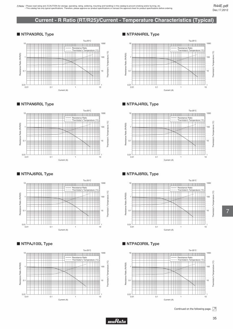
Current - R Ratio (RT/R25)/Current - Temperature Characteristics (Typical)
0.01 0.1
Current (A)
Ta=25°C
1 10
Resistance RatioThermistor's Temperature (°C)
10
1
0.1
0.01
1000
100
10
1
Res
ista
nce
Rat
io (
Rt/R
25)
The
rmis
tor's
Tem
pera
ture
(°C
)
c NTPAN3R0L Type
0.01 0.1
Current (A)
Ta=25°C
1 10
Resistance RatioThermistor's Temperature (°C)
10
1
0.1
0.01
1000
100
10
1
Res
ista
nce
Rat
io (
Rt/R
25)
The
rmis
tor's
Tem
pera
ture
(°C
)
c NTPAN4R0L Type
0.01 0.1
Current (A)
Ta=25°C
1 10
Resistance RatioThermistor's Temperature (°C)
10
1
0.1
0.01
1000
100
10
1
Res
ista
nce
Rat
io (
Rt/R
25)
The
rmis
tor's
Tem
pera
ture
(°C
)c NTPAN6R0L Type
0.01 0.1
Current (A)
Ta=25°C
1 10
Resistance RatioThermistor's Temperature (°C)
10
1
0.1
0.01
1000
100
10
1
Res
ista
nce
Rat
io (
Rt/R
25)
The
rmis
tor's
Tem
pera
ture
(°C
)
c NTPAJ4R0L Type
0.01 0.1
Current (A)
Ta=25°C
1 10
Resistance RatioThermistor's Temperature (°C)
10
1
0.1
0.01
1000
100
10
1
Res
ista
nce
Rat
io (
Rt/R
25)
The
rmis
tor's
Tem
pera
ture
(°C
)
c NTPAJ6R0L Type
0.01 0.1
Current (A)
Ta=25°C
1 10
Resistance RatioThermistor's Temperature (°C)
10
1
0.1
0.01
1000
100
10
1
Res
ista
nce
Rat
io (
Rt/R
25)
The
rmis
tor's
Tem
pera
ture
(°C
)
c NTPAJ8R0L Type
0.01 0.1
Current (A)
Ta=25°C
1 10
Resistance RatioThermistor's Temperature (°C)
10
1
0.1
0.01
1000
100
10
1
Res
ista
nce
Rat
io (
Rt/R
25)
The
rmis
tor's
Tem
pera
ture
(°C
)
c NTPAJ100L Type
0.01 0.1
Current (A)
Ta=25°C
1 10
Resistance RatioThermistor's Temperature (°C)
10
1
0.1
0.01
1000
100
10
1
Res
ista
nce
Rat
io (
Rt/R
25)
The
rmis
tor's
Tem
pera
ture
(°C
)
c NTPAD3R9L Type
Continued on the following page.
R44E.pdfDec.17,2012
35
!Note • Please read rating and !CAUTION (for storage, operating, rating, soldering, mounting and handling) in this catalog to prevent smoking and/or burning, etc.• This catalog has only typical specifi cations. Therefore, please approve our product specifi cations or transact the approval sheet for product specifi cations before ordering.
7
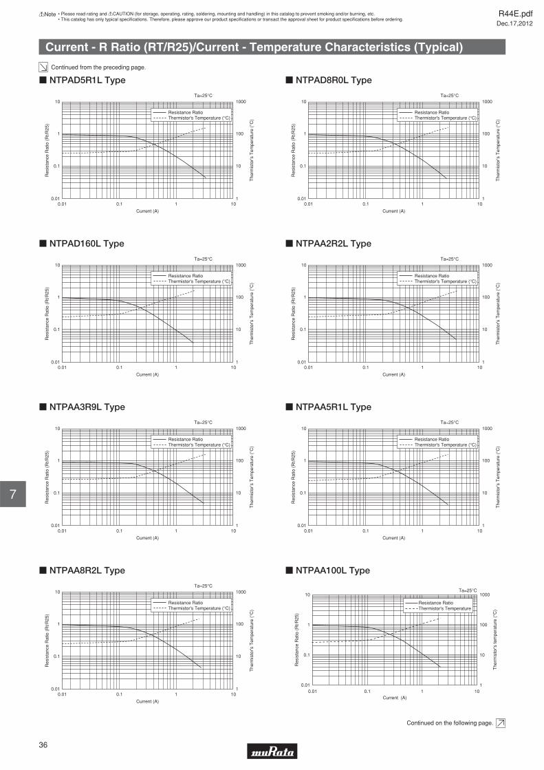
Current - R Ratio (RT/R25)/Current - Temperature Characteristics (Typical)
Continued from the preceding page.
0.01 0.1
Current (A)
Ta=25°C
1 10
Resistance RatioThermistor's Temperature (°C)
10
1
0.1
0.01
1000
100
10
1
Res
ista
nce
Rat
io (
Rt/R
25)
The
rmis
tor's
Tem
pera
ture
(°C
)
c NTPAD5R1L Type
0.01 0.1
Current (A)
Ta=25°C
1 10
Resistance RatioThermistor's Temperature (°C)
10
1
0.1
0.01
1000
100
10
1
Res
ista
nce
Rat
io (
Rt/R
25)
The
rmis
tor's
Tem
pera
ture
(°C
)
c NTPAD8R0L Type
0.01 0.1
Current (A)
Ta=25°C
1 10
Resistance RatioThermistor's Temperature (°C)
10
1
0.1
0.01
1000
100
10
1
Res
ista
nce
Rat
io (
Rt/R
25)
The
rmis
tor's
Tem
pera
ture
(°C
)c NTPAD160L Type
0.01 0.1
Current (A)
Ta=25°C
1 10
Resistance RatioThermistor's Temperature (°C)
10
1
0.1
0.01
1000
100
10
1
Res
ista
nce
Rat
io (
Rt/R
25)
The
rmis
tor's
Tem
pera
ture
(°C
)
c NTPAA2R2L Type
0.01 0.1
Current (A)
Ta=25°C
1 10
Resistance RatioThermistor's Temperature (°C)
10
1
0.1
0.01
1000
100
10
1
Res
ista
nce
Rat
io (
Rt/R
25)
The
rmis
tor's
Tem
pera
ture
(°C
)
c NTPAA3R9L Type
0.01 0.1
Current (A)
Ta=25°C
1 10
Resistance RatioThermistor's Temperature (°C)
10
1
0.1
0.01
1000
100
10
1
Res
ista
nce
Rat
io (
Rt/R
25)
The
rmis
tor's
Tem
pera
ture
(°C
)
c NTPAA5R1L Type
0.01 0.1
Current (A)
Ta=25°C
1 10
Resistance RatioThermistor's Temperature (°C)
10
1
0.1
0.01
1000
100
10
1
Res
ista
nce
Rat
io (
Rt/R
25)
The
rmis
tor's
Tem
pera
ture
(°C
)
c NTPAA8R2L Type
0.01
0.1
1
10
0.01 0.1 1 10
Res
ista
nce
Rat
io (
Rt/R
25)
The
rmis
tor's
tem
pera
ture
(°C
)
1
10
100
1000
Resistance RatioThermistor's Temperature
Ta=25°C
Current (A)
c NTPAA100L Type
Continued on the following page.
R44E.pdfDec.17,2012
36
!Note • Please read rating and !CAUTION (for storage, operating, rating, soldering, mounting and handling) in this catalog to prevent smoking and/or burning, etc.• This catalog has only typical specifi cations. Therefore, please approve our product specifi cations or transact the approval sheet for product specifi cations before ordering.
7
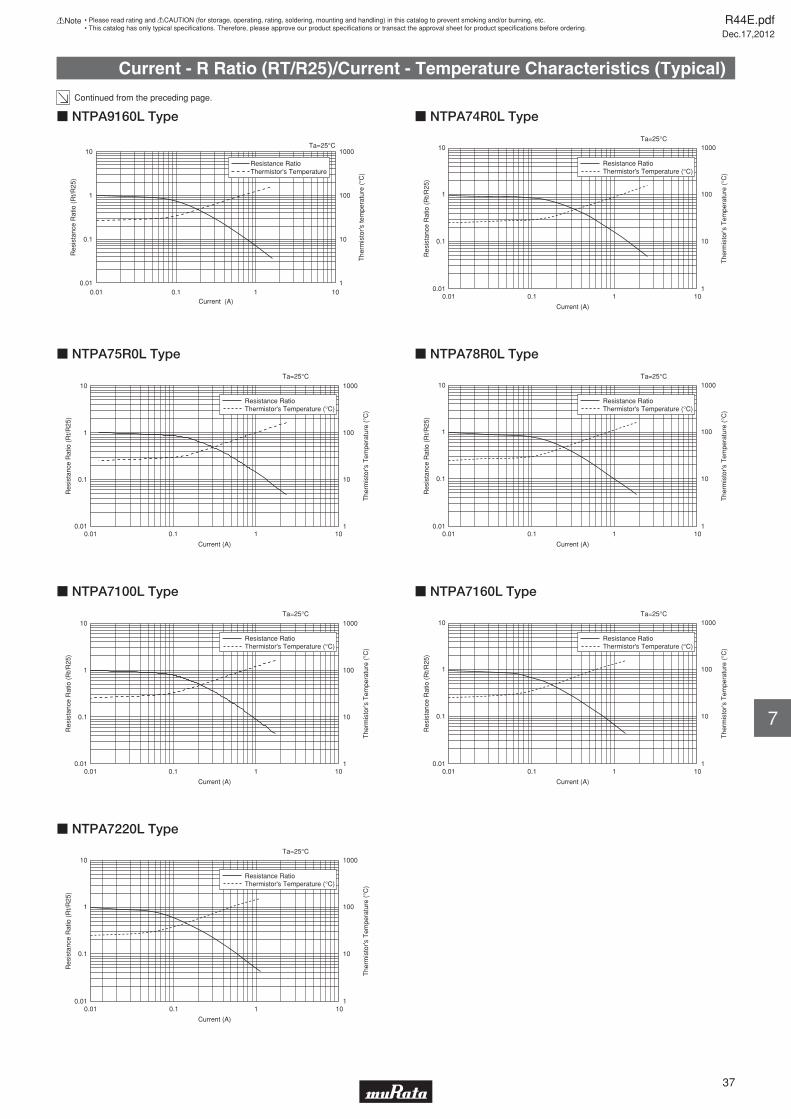
Current - R Ratio (RT/R25)/Current - Temperature Characteristics (Typical)
Continued from the preceding page.
0.01
0.1
1
10
0.01 0.1 1 10
Res
ista
nce
Rat
io (
Rt/R
25)
The
rmis
tor's
tem
pera
ture
(°C
)
1
10
100
1000
Resistance RatioThermistor's Temperature
Ta=25°C
Current (A)
c NTPA9160L Type
0.01 0.1
Current (A)
Ta=25°C
1 10
Resistance RatioThermistor's Temperature (°C)
10
1
0.1
0.01
1000
100
10
1
Res
ista
nce
Rat
io (
Rt/R
25)
The
rmis
tor's
Tem
pera
ture
(°C
)
c NTPA74R0L Type
0.01 0.1
Current (A)
Ta=25°C
1 10
Resistance RatioThermistor's Temperature (°C)
10
1
0.1
0.01
1000
100
10
1
Res
ista
nce
Rat
io (
Rt/R
25)
The
rmis
tor's
Tem
pera
ture
(°C
)c NTPA75R0L Type
0.01 0.1
Current (A)
Ta=25°C
1 10
Resistance RatioThermistor's Temperature (°C)
10
1
0.1
0.01
1000
100
10
1
Res
ista
nce
Rat
io (
Rt/R
25)
The
rmis
tor's
Tem
pera
ture
(°C
)
c NTPA78R0L Type
0.01 0.1
Current (A)
Ta=25°C
1 10
Resistance RatioThermistor's Temperature (°C)
10
1
0.1
0.01
1000
100
10
1
Res
ista
nce
Rat
io (
Rt/R
25)
The
rmis
tor's
Tem
pera
ture
(°C
)
c NTPA7100L Type
0.01 0.1
Current (A)
Ta=25°C
1 10
Resistance RatioThermistor's Temperature (°C)
10
1
0.1
0.01
1000
100
10
1
Res
ista
nce
Rat
io (
Rt/R
25)
The
rmis
tor's
Tem
pera
ture
(°C
)
c NTPA7160L Type
0.01 0.1
Current (A)
Ta=25°C
1 10
Resistance RatioThermistor's Temperature (°C)
10
1
0.1
0.01
1000
100
10
1
Res
ista
nce
Rat
io (
Rt/R
25)
The
rmis
tor's
Tem
pera
ture
(°C
)
c NTPA7220L Type
R44E.pdfDec.17,2012
37
!Note • Please read rating and !CAUTION (for storage, operating, rating, soldering, mounting and handling) in this catalog to prevent smoking and/or burning, etc.• This catalog has only typical specifi cations. Therefore, please approve our product specifi cations or transact the approval sheet for product specifi cations before ordering.
7
Inrush Current Suppression Lead Type !Caution/Notice
c !Caution (Storage and Operating Conditions)
c !Caution (Others)Be sure to provide an appropriate fail-safe function on your product to prevent secondary damages that may be caused by the abnormal function or the failure of our product.
c Notice (Storage and Operating Conditions)To keep solderability of product from declining, thefollowing storage condition is recommended.1. Storage condition: Temperature -10 to +40 degrees C Humidity less than 75%RH (not dewing condition)2. Storage term: Use this product within 6 months after delivery by fi rst-in and fi rst-out stocking system.
3. Handling after unpacking: After unpacking, reseal product promptly or store it in a sealed container with a drying agent.4. Storage place: Do not store this product in corrosive gas (Sulfuric acid gas, Chlorine gas, etc.) or in direct sunlight.
c Notice (Rating)Use this product within the specifi ed temperature range.Higher temperature may cause deterioration of the characteristics or the material quality of this product.
c Notice (Soldering and Mounting)1. Be sure that the preheat-up does not melt the soldering of this product. Excessive heat may cause failure to open, short or insulation break down.2. Do not touch the body with soldering iron. The soldering point should be min. 5mm away from the root of lead wire.
R44E.pdfDec.17,2012
38
!Note • Please read rating and !CAUTION (for storage, operating, rating, soldering, mounting and handling) in this catalog to prevent smoking and/or burning, etc.• This catalog has only typical specifi cations. Therefore, please approve our product specifi cations or transact the approval sheet for product specifi cations before ordering.
7
1. This product is designed for the Switching Power Supply with smoothing capacitors. Other applications of this product may result in fi re.2. Use this product within the specifi ed maximum current. Otherwise it may catch fi re in the worst case.3. Use this product with smoothing capacitor within the specifi ed maximum capacitance value. Otherwise it may catch fi re in the worst case.4. This product is designed for application in an ordinary environment (normal room temperature, humidity and atmospheric pressure).
Do not use under the following conditions because all these factors can deteriorate the product characteristics cause failure and burn-out. (1) Corrosive gas or deoxidizing gas. (Chlorine gas, Hydrogen sulfi de gas, Ammonia gas, Sulfuric acid gas, Nitric oxide gas, etc.) (2) Volatile or fl ammable gas (3) Dusty conditions (4) Under high or low pressure (5) Wet or humid conditions (6) Near with salt water, oils, chemical liquids or organic solvents (7) Strong vibrations (8) Other places where similar hazardous conditions exist.
Inrush Current Suppression Lead Type !Caution/Notice
c Notice (Handling)
c Notice (Others)
R44E.pdfDec.17,2012
39
!Note • Please read rating and !CAUTION (for storage, operating, rating, soldering, mounting and handling) in this catalog to prevent smoking and/or burning, etc.• This catalog has only typical specifi cations. Therefore, please approve our product specifi cations or transact the approval sheet for product specifi cations before ordering.
7
1. When this product is operated, temperature of some area may be about 160 (degree C). Use proper surrounding parts and material which withstand such temperature. If they are inadequate and kept at high temperature for long time, they may be deteriorated or may produce harmful gas. And, such harmful gas may deteriorate the element of this product.2. This product does not have waterproof construction. Splashed water may cause failure mode such as deterioration of characteristics or current leak. So, do not apply cleaning to immerse it into water or any solvent.
3. The ceramic element of this product is fragile, and care must be taken not to load an excessive press-force or not to give a shock at handling. Such forces may cause cracking or chipping to the element.4. Do not apply an excessive force to the lead wire. Otherwise, it may cause break off junction between lead wire and element, or may crack element. So, fi x lead wire of element side when lead wire is bent or cut.
1. This product may allow passing higher current than its initial value when it receives inrush current again just after the last one until it cools down and recovers its original resistance enough. Be sure the highest current under actual condition on the operating repetition and the operating temperature.
2. The resin coating of this product does not guarantee insulating. Keep an adequate insulating distance to surrounding parts.
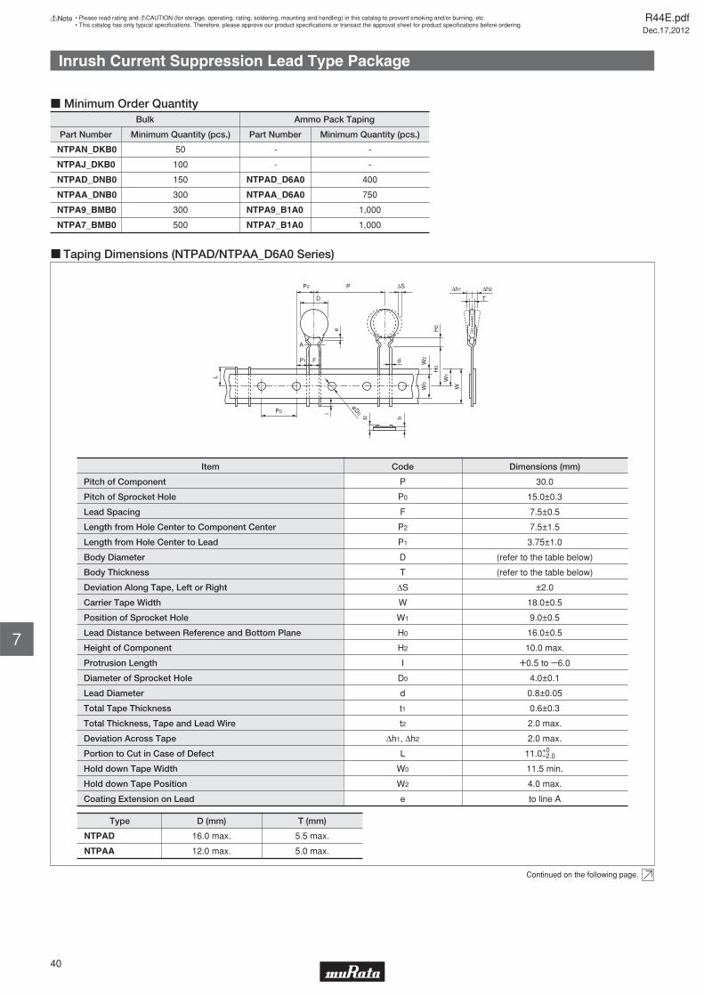
Inrush Current Suppression Lead Type Package
Part Number
Bulk
Minimum Quantity (pcs.)
-50
-100
400150
750300
1,000300
1,000500
Part Number
Ammo Pack Taping
Minimum Quantity (pcs.)
NTPAN_DKB0
NTPAJ_DKB0
NTPAD_DNB0
NTPAA_DNB0
NTPA9_BMB0
NTPA7_BMB0
-
-
NTPAD_D6A0
NTPAA_D6A0
NTPA9_B1A0
NTPA7_B1A0
c Minimum Order Quantity
c Taping Dimensions (NTPAD/NTPAA_D6A0 Series)
Pitch of Component
Pitch of Sprocket Hole
Lead Spacing
Length from Hole Center to Lead
Length from Hole Center to Component Center
Body Diameter
Deviation Along Tape, Left or Right
Carrier Tape Width
Position of Sprocket Hole
Lead Distance between Reference and Bottom Plane
Height of Component
Protrusion Length
Diameter of Sprocket Hole
Lead Diameter
Total Tape Thickness
Total Thickness, Tape and Lead Wire
Deviation Across Tape
Portion to Cut in Case of Defect
Hold down Tape Width
Hold down Tape Position
Coating Extension on Lead
P
P0
F
P1
P2
D
ΔS
W
W1
H0
H2
I
D0
d
t1
t2
Δh1, Δh2
L
W0
W2
e
30.0
15.0±0.3
7.5±0.5
7.5±1.5
3.75±1.0
(refer to the table below)
Body Thickness T (refer to the table below)
±2.0
18.0±0.5
16.0±0.5
10.0 max.
W0.5 to Y6.0
4.0±0.1
0.8±0.05
0.6±0.3
2.0 max.
2.0 max.
11.5 min.
4.0 max.
to line A
CodeItem Dimensions (mm)
9.0±0.5
11.0+0–2.0
NTPAD
NTPAA
Type D (mm) T (mm)
16.0 max. 5.5 max.
12.0 max. 5.0 max.
W0
W2
W
W1
H0
H2
Δh2Δh1
e
ΔSP2 P
D
P1
P0
F d
l
øD0
L
t2 t1
T
A
Continued on the following page.
R44E.pdfDec.17,2012
40
!Note • Please read rating and !CAUTION (for storage, operating, rating, soldering, mounting and handling) in this catalog to prevent smoking and/or burning, etc.• This catalog has only typical specifi cations. Therefore, please approve our product specifi cations or transact the approval sheet for product specifi cations before ordering.
7
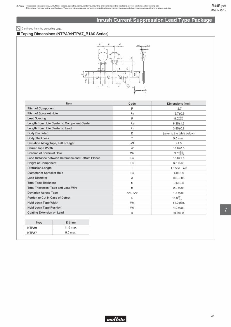
Inrush Current Suppression Lead Type Package
Continued from the preceding page.
c Taping Dimensions (NTPA9/NTPA7_B1A0 Series)
Pitch of Component
Pitch of Sprocket Hole
Lead Spacing
Length from Hole Center to Lead
Length from Hole Center to Component Center
Body Diameter
Deviation Along Tape, Left or Right
Carrier Tape Width
Position of Sprocket Hole
Lead Distance between Reference and Bottom Planes
Height of Component
Protrusion Length
Diameter of Sprocket Hole
Lead Diameter
Total Tape Thickness
Total Thickness, Tape and Lead Wire
Deviation Across Tape
Portion to Cut in Case of Defect
Hold down Tape Width
Hold down Tape Position
Coating Extension on Lead
P
P0
F
P1
P2
D
ΔS
W
W1
H0
H2
I
D0
d
t1
t2
Δh1, Δh2
L
W0
W2
e
12.7
12.7±0.3
5.0
6.35±1.3
3.85±0.8
(refer to the table below)
Body Thickness T 5.0 max.
±1.5
18.0±0.5
16.0±1.0
6.0 max.
W0.5 to Y4.0
4.0±0.3
0.6±0.05
0.6±0.3
2.0 max.
1.5 max.
11.0 min.
4.0 max.
to line A
CodeItem Dimensions (mm)
9.0
11.0+0–2.0
+0.8–0.3
+0.5–0.75
W0
W2
W
W1
H0
H2
Δh2Δh1
e
ΔSP2 P
D
A
P1
P0
F d
l
øD0
L
t2 t1
T
Type D (mm)
11.0 max.
9.0 max.
NTPA9
NTPA7
R44E.pdfDec.17,2012
41
!Note • Please read rating and !CAUTION (for storage, operating, rating, soldering, mounting and handling) in this catalog to prevent smoking and/or burning, etc.• This catalog has only typical specifi cations. Therefore, please approve our product specifi cations or transact the approval sheet for product specifi cations before ordering.
7
R44E.pdfDec.17,2012
!Note • Please read rating and !CAUTION (for storage, operating, rating, soldering, mounting and handling) in this catalog to prevent smoking and/or burning, etc.• This catalog has only typical specifi cations. Therefore, please approve our product specifi cations or transact the approval sheet for product specifi cations before ordering.