nuclear thermal rocket propulsion systems - lawrence · · 2011-05-13nuclear thermal rocket...
TRANSCRIPT
NUCLEAR THERMAL ROCKET PROPULSION SYSTEMS, IAA WHITE PAPER
PARIS, FRANCE, MARCH 2005 Lt Col Timothy J. Lawrence
U.S. Air Force Academy Department of Astronautics
2354 Fairchild Drive Suite 1M147 USAFA, Colorado, 80840 USA [email protected]
Version 1 Submitted to Dr Claudio Bruno on 12 January 2005 Ideas for using nuclear energy for space propulsion began shortly after the first controlled nuclear chain reaction in 1942. Starting in the late 1940s, several development programs were pursued by the United States Air Force, the Atomic Energy Commission (now the US Department of Energy), and the National Aeronautics and Space Administration. Some of the systems developed from these programs are still in use today. To use nuclear power for space propulsion, a propellant is heated in a suitable nuclear reactor to create hot, high-pressure gas which is expanded through a nozzle. The resultant high thrust and high specific impulse enhance or enable missions which may not be feasible using conventional chemical rocket engines. Nuclear reactors, at the simplest level, are heat sources; they can heat a propellant directly (nuclear thermal) or create electricity (nuclear electric). Introduction Most rockets are thermally driven gas devices in which energy is added in the form of heat. This heat energy ejects propellant from the engine, giving us the required momentum exchange or thrust. Energy can come from any number of sources. In chemical propulsion, the propellant releases energy through combustion. In a nuclear rocket, the propellant heats up when energy releases from the controlled fission of uranium or other fissionable material. Fission involves the absorption of neutrons in a fuel material such as uranium. This absorption excites the uranium atom until it splits into fragments and releases, on average, two new nuclei and one to three free neutrons. The fission fragments have high kinetic energy from the release of nuclear binding energy. This energy becomes thermal energy through collisions and interactions with other atoms. The neutrons also give up kinetic energy and slow down so they can be absorbed into the other fuel material. This process occurs more readily in lighter materials such as carbon, hydrogen, and beryllium because of their cross sections. If each fission results in one other fission event, the core is said to be critical. Neutrons can either be absorbed by other engine materials or can leak from the reactor. The neutrons that leak out are lost from the cycle. Two or three neutrons are usually released in each fission event to ensure that at least one is absorbed by the fuel and causes another fission event.
REPORT DOCUMENTATION PAGE Form Approved
OMB No. 0704-0188 Public reporting burden for this collection of information is estimated to average 1 hour per response, including the time for reviewing instructions, searching existing data sources, gathering and maintaining the data needed, and completing and reviewing this collection of information. Send comments regarding this burden estimate or any other aspect of this collection of information, including suggestions for reducing this burden to Department of Defense, Washington Headquarters Services, Directorate for Information Operations and Reports (0704-0188), 1215 Jefferson Davis Highway, Suite 1204, Arlington, VA 22202-4302. Respondents should be aware that notwithstanding any other provision of law, no person shall be subject to any penalty for failing to comply with a collection of information if it does not display a currently valid OMB control number. PLEASE DO NOT RETURN YOUR FORM TO THE ABOVE ADDRESS. 1. REPORT DATE (DD-MM-YYYY) 18-03-2005
2. REPORT TYPE White Paper
3. DATES COVERED (From - To) 18 Mar 2005
4. TITLE AND SUBTITLE NUCLEAR THERMAL ROCKET PROPULSION SYSTEMS
5a. CONTRACT NUMBER N/A
5b. GRANT NUMBER N/A
5c. PROGRAM ELEMENT NUMBER N/A
6. AUTHOR(S) LtCol Timothy Lawrence
5d. PROJECT NUMBER N/A
5e. TASK NUMBER N/A
5f. WORK UNIT NUMBERN/A
7. PERFORMING ORGANIZATION NAME(S) AND ADDRESS(ES)
8. PERFORMING ORGANIZATION REPORT NUMBER
Department of Astronautics 2354 Fairchild Dr. US Air Force Academy, CO 80840
N/A
9. SPONSORING / MONITORING AGENCY NAME(S) AND ADDRESS(ES) 10. SPONSOR/MONITOR’S ACRONYM(S) N/A N/A 11. SPONSOR/MONITOR’S REPORT NUMBER(S) N/A 12. DISTRIBUTION / AVAILABILITY STATEMENT A – Approved for public release; distribution is unlimited.
13. SUPPLEMENTARY NOTES
14. ABSTRACT Ideas for using nuclear energy for space propulsion began shortly after the first controlled nuclear chain reaction in 1942. Starting in the late 1940s, several development programs were pursued by the United States Air Force, the Atomic Energy Commission (now the US Department of Energy), and the National Aeronautics and Space Administration. Some of the systems developed from these programs are still in use today. To use nuclear power for space propulsion, a propellant is heated in a suitable nuclear reactor to create hot, high-pressure gas which is expanded through a nozzle. The resultant high thrust and high specific impulse enhance or enable missions which may not be feasible using conventional chemical rocket engines. Nuclear reactors, at the simplest level, are heat sources; they can heat a propellant directly (nuclear thermal) or create electricity (nuclear electric).
15. SUBJECT TERMS Nuclear Energy, Propulsion, Nuclear Reactor, Nuclear Propulsion
16. SECURITY CLASSIFICATION OF:
17. LIMITATION OF ABSTRACT
18. NUMBER OF PAGES
19a. NAME OF RESPONSIBLE PERSON LtCol Tim Lawrence
a. REPORT U
b. ABSTRACT U
c. THIS PAGE U
N/A 16
19b. TELEPHONE NUMBER (include area code) (719) 333-4110
Standard Form 298 (Rev. 8-98) Prescribed by ANSI Std. Z39.18
INSTRUCTIONS FOR COMPLETING SF 298
1. REPORT DATE. Full publication date, including day, month, if available. Must cite at least the year and be Year 2000 compliant, e.g. 30-06-1998; xx-06-1998-, xx-xx-1998.
2. REPORT TYPE. State the type of report, such as final, technical, interim, memorandum, master's thesis, progress, quarterly, research, special, group study, etc.
3. DATES COVERED. Indicate the time during which the work was performed and the report was written, e.g., Jun 1997 -Jun 1998; 1-10 Jun 1996; May - Nov 1998; Nov 1998.
4. TITLE. Enter title and subtitle with volume number and part number, if applicable. On classified documents, enter the title classification in parentheses.
Ba. CONTRACT NUMBER. Enter all contract numbers as they appear in the report, e.g. F33615-86-C-5169.
5b. GRANT NUMBER. Enter all grant numbers as they appear in the report, e.g. AFOSR-82-1234.
5c. PROGRAM ELEMENT NUMBER. Enter all program element numbers as they appear in the report, e.g. 61101A.
5d. PROJECT NUMBER. Enter all project nurnbers as they appear in the report, e.g. 1F665702D1257; ILIR.
5e. TASK NUMBER. Enter all task numbers as they appear in the report, e.g. 05; RF0330201; T4112.
5f. WORK UNIT NUMBER. Enter all work unit numbers as they appear in the report, e.g. 001; AFAPL30480105.
6. AUTHOR(S). Enter name(s) of person(s) responsible for writing the report, performing the research, or credited with the content of the report. The form of entry is the last name, first name, middle initial, and additional qualifiers separated by commas, e.g. Smith, Richard, J, Jr.
7. PERFORMING ORGANIZATION NAME(S) AND ADDRESS(ES). Self-explanatory.
8. PERFORMING ORGANIZATION REPORT NUMBER. Enter all unique alphanumeric report numbers assigned by the performing organization, e.g. BRL-1234; AFWL-TR-85-4017-Vol-21-PT-2.
9. SPONSORING/MONITORING AGENCY NAME(S) AND ADDRESS(ES). Enter the name and address of the organization(s) financially responsible for and monitoring the work.
10. SPONSOR/MONITOR'S ACRONYM(S). Enter, if available, e.g. BRL, ARDEC, NADC.
11. SPONSOR/MONITOR'S REPORT NUMBER(S). Enter report number as assigned by the sponsoring/ monitoring agency, if available, e.g. BRL-TR-829; -21 5.
12. DISTRIBUTION/AVAILABILITY STATEMENT. Use agency-mandated availability statements to indicate the public availability or distribution limitations of the report. If additional limitations/ restrictions or special markings are indicated, follow agency authorization procedures, e.g. RD/FRD, PROPIN, ITAR, etc. Include copyright information.
13. SUPPLEMENTARY NOTES. Enter information not included elsewhere such as: prepared in cooperation with; translation of; report supersedes; old edition number, etc.
14. ABSTRACT. A brief (approximately 200 words) factual summary of the most significant information.
15. SUBJECT TERMS. Key words or phrases identifying major concepts in the report.
16. SECURITY CLASSIFICATION. Enter security classification in accordance with security classification regulations, e.g. U, C, S, etc. If this form contains classified information, stamp classification level on the top and bottom of this page.
17. LIMITATION OF ABSTRACT. This block must be completed to assign a distribution limitation to the abstract. Enter UU (Unclassified Unlimited) or SAR (Same as Report). An entry in this block is necessary if the abstract is to be limited.
Standard Form 298 Back (Rev. 8/98)
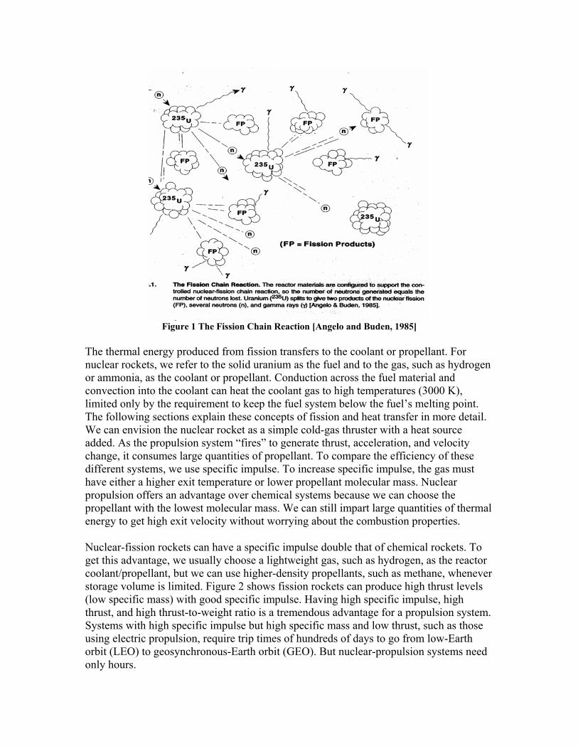
Figure 1 The Fission Chain Reaction [Angelo and Buden, 1985]
The thermal energy produced from fission transfers to the coolant or propellant. For nuclear rockets, we refer to the solid uranium as the fuel and to the gas, such as hydrogen or ammonia, as the coolant or propellant. Conduction across the fuel material and convection into the coolant can heat the coolant gas to high temperatures (3000 K), limited only by the requirement to keep the fuel system below the fuel’s melting point. The following sections explain these concepts of fission and heat transfer in more detail. We can envision the nuclear rocket as a simple cold-gas thruster with a heat source added. As the propulsion system “fires” to generate thrust, acceleration, and velocity change, it consumes large quantities of propellant. To compare the efficiency of these different systems, we use specific impulse. To increase specific impulse, the gas must have either a higher exit temperature or lower propellant molecular mass. Nuclear propulsion offers an advantage over chemical systems because we can choose the propellant with the lowest molecular mass. We can still impart large quantities of thermal energy to get high exit velocity without worrying about the combustion properties. Nuclear-fission rockets can have a specific impulse double that of chemical rockets. To get this advantage, we usually choose a lightweight gas, such as hydrogen, as the reactor coolant/propellant, but we can use higher-density propellants, such as methane, whenever storage volume is limited. Figure 2 shows fission rockets can produce high thrust levels (low specific mass) with good specific impulse. Having high specific impulse, high thrust, and high thrust-to-weight ratio is a tremendous advantage for a propulsion system. Systems with high specific impulse but high specific mass and low thrust, such as those using electric propulsion, require trip times of hundreds of days to go from low-Earth orbit (LEO) to geosynchronous-Earth orbit (GEO). But nuclear-propulsion systems need only hours.
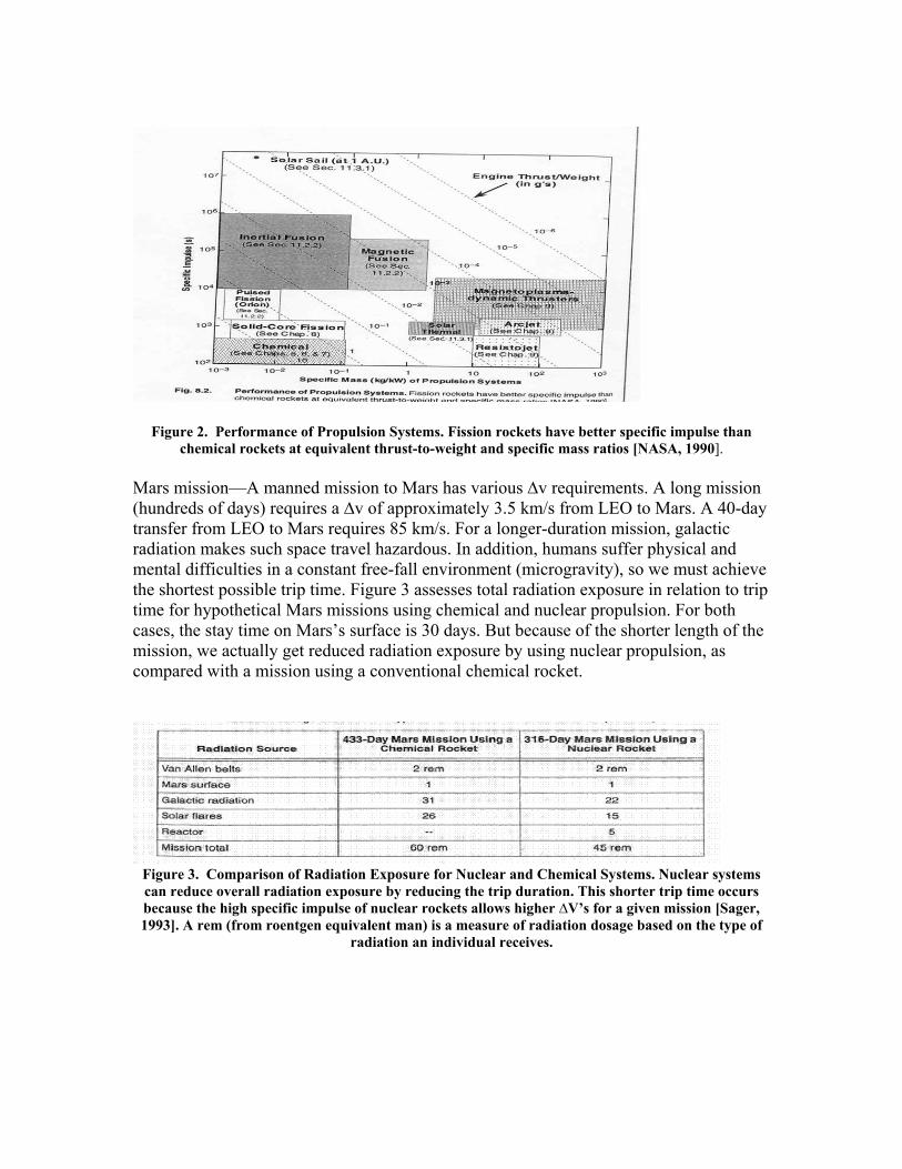
Figure 2. Performance of Propulsion Systems. Fission rockets have better specific impulse than chemical rockets at equivalent thrust-to-weight and specific mass ratios [NASA, 1990].
Mars mission—A manned mission to Mars has various ∆v requirements. A long mission (hundreds of days) requires a ∆v of approximately 3.5 km/s from LEO to Mars. A 40-day transfer from LEO to Mars requires 85 km/s. For a longer-duration mission, galactic radiation makes such space travel hazardous. In addition, humans suffer physical and mental difficulties in a constant free-fall environment (microgravity), so we must achieve the shortest possible trip time. Figure 3 assesses total radiation exposure in relation to trip time for hypothetical Mars missions using chemical and nuclear propulsion. For both cases, the stay time on Mars’s surface is 30 days. But because of the shorter length of the mission, we actually get reduced radiation exposure by using nuclear propulsion, as compared with a mission using a conventional chemical rocket.
Figure 3. Comparison of Radiation Exposure for Nuclear and Chemical Systems. Nuclear systems can reduce overall radiation exposure by reducing the trip duration. This shorter trip time occurs because the high specific impulse of nuclear rockets allows higher ∆V’s for a given mission [Sager, 1993]. A rem (from roentgen equivalent man) is a measure of radiation dosage based on the type of
radiation an individual receives.
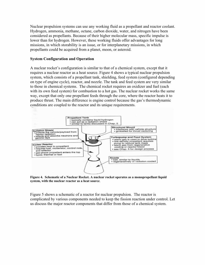
Nuclear propulsion systems can use any working fluid as a propellant and reactor coolant. Hydrogen, ammonia, methane, octane, carbon dioxide, water, and nitrogen have been considered as propellants. Because of their higher molecular mass, specific impulse is lower than for hydrogen. However, these working fluids offer advantages for long missions, in which storability is an issue, or for interplanetary missions, in which propellants could be acquired from a planet, moon, or asteroid. System Configuration and Operation A nuclear rocket’s configuration is similar to that of a chemical system, except that it requires a nuclear reactor as a heat source. Figure 4 shows a typical nuclear propulsion system, which consists of a propellant tank, shielding, feed system (configured depending on type of engine cycle), reactor, and nozzle. The tank and feed system are very similar to those in chemical systems. The chemical rocket requires an oxidizer and fuel (each with its own feed system) for combustion to a hot gas. The nuclear rocket works the same way, except that only one propellant feeds through the core, where the reactor heats it to produce thrust. The main difference is engine control because the gas’s thermodynamic conditions are coupled to the reactor and its unique requirements.
Figure 4. Schematic of a Nuclear Rocket. A nuclear rocket operates as a monopropellant liquid system, with the nuclear reactor as a heat source.
Figure 5 shows a schematic of a reactor for nuclear propulsion. The reactor is complicated by various components needed to keep the fission reaction under control. Let us discuss the major reactor components that differ from those of a chemical system.
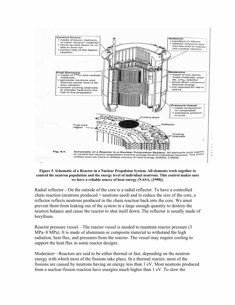
Figure 5. Schematic of a Reactor in a Nuclear Propulsion System. All elements work together to control the neutron population and the energy level of individual neutrons. This control makes sure
we have a reliable source of heat energy (NASA, [1990]). Radial reflector—On the outside of the core is a radial reflector. To have a controlled chain reaction (neutrons produced = neutrons used) and to reduce the size of the core, a reflector reflects neutrons produced in the chain reaction back into the core. We must prevent them from leaking out of the system in a large enough quantity to destroy the neutron balance and cause the reactor to shut itself down. The reflector is usually made of beryllium. Reactor pressure vessel—The reactor vessel is needed to maintain reactor pressure (3 MPa–8 MPa). It is made of aluminum or composite material to withstand the high radiation, heat flux, and pressures from the reactor. The vessel may require cooling to support the heat flux in some reactor designs. Moderator—Reactors are said to be either thermal or fast, depending on the neutron energy with which most of the fissions take place. In a thermal reactor, most of the fissions are caused by neutrons having an energy less than 1 eV. Most neutrons produced from a nuclear-fission reaction have energies much higher than 1 eV. To slow the
neutrons down, we use a moderator assembly made of a material with a low atomic mass (beryllium, plastics, lithium hydride, graphite). In a fast reactor, the energy range in which most of the fissions take place is much wider, extending from 100 keV to the top range of the fission spectrum (15 MeV). If we wish to build a fast reactor, we avoid light elements (moderating materials) and have no moderator. Some reactors effectively mix moderating material with fuel material to limit the system’s size and mass. Fuel-element assembly—The fuel-element assembly contains the uranium fuel and propellant/coolant flow channels. The fuel produces the heat to be transferred to the propellant flowing past the fuel. Different configurations of a fuel element can take advantage of surface area to better transfer heat and to make sure some kind of barrier contains the fission products. The reflector, control rods, and moderator are placed around the fuel to maintain the proper flow and control of neutrons. Control rods or drums—The control rods or drums contain materials (usually boron) that absorb neutrons to decrease the neutron population. The rods control the reaction rate and can shut the reactor down. This material is known as a “poison” because it lowers the number of fission reactions when inserted in the core. The rods are dispersed around the core to ensure the neutron population can be properly controlled and adjusted to meet engine power level requirements. The control rods can be inserted into the reactor axially or rotated. For the axial insertion, the depth of the rods controls the amount of neutrons captured. For the rotation insertion, one side of the rod contains boron, whereas the other side contains beryllium. When the boron side is rotated into place, neutrons are absorbed. When the beryllium side is rotated, neutrons are reflected back into the core. Coolant flow paths—Coolant piping cools components and provides the propellant gas needed to generate thrust from the reactor. We usually want propellant to be completely vaporized before it enters the reactor core. Now that we basically understand most of the components associated with the reactor, let us look at the operation of the core. The core is placed on the launch pad with the control poison fully inserted. With the control poison in this position, the core produces no power and has negligible radioactivity (only the natural radioactivity of the fuel). This condition allows workers to handle the reactor with no protective shielding. Once the mission requires thrust, the control poison is withdrawn (either lifted vertically or rotated outward) and a neutron source is put into the reactor to provide the initial neutrons for fissioning. With the control poison withdrawn, the fissioning causes the thermal power to increase exponentially to the desired power level. When the poison is removed, the feed system immediately supplies gas to the core for cooling and thrust production. When the reactor reaches the desired full-power level, the control poison’s position is adjusted to keep the power at a steady-state (number of neutrons produced = number of neutrons used). This is a delicate balance. At mission’s end, the control poisons are inserted back into the core and the power decays exponentially. But the reactor needs to cool down for some time, depending on how long the core was at full power, and it may or may not need active cooling. This
cooling may be necessary because of delayed neutrons and residual heat production that result from radioactive decay of by-products from the fission process (“fission products”). Concepts The following section discusses nuclear systems that have been developed or proposed for propulsion applications in space. Many other possibilities exist (18 concepts proposed by NASA [1990]), but we believe these are the most likely US candidates for near-term missions. NERVA Derivative or Enabler The NERVA (Nuclear Engine for Rocket Vehicle Applications) is a modified design of the reactor used in the NERVA program (NERVA-1). The NERVA program started in 1947 under the U.S. Air Force to design a reactor that could propel intercontinental ballistic missiles (ICBMs). In 1958, NASA took control of NERVA as part of their space-exploration program. NASA ran the program until 1972, achieving:
-28 full-power tests with restarts -Up to 30-minute test duration, total life 90 minutes -Reactor sizes ranging from 300 MW to 200,000 MW -Design of a hydrogen flow system -Development of a way to contain affluents (propellant exhaust gases) for safe ground testing (used only in later tests) -Development of a high-temperature fuel (5500 F) -Solution to the problem of fuel erosion from hot hydrogen -Specific impulse levels as high as 835 seconds -Thrust levels as high as 890,000 N -Thrust to weight ratios of 3 to 4
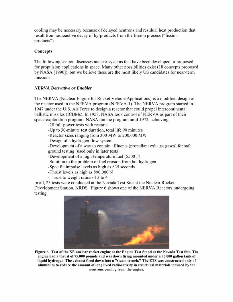
In all, 23 tests were conducted at the Nevada Test Site at the Nuclear Rocket Development Station, NRDS. Figure 6 shows one of the NERVA Reactors undergoing testing.
Figure 6. Test of the XE nuclear rocket engine at the Engine Test Stand at the Nevada Test Site. The
engine had a thrust of 75,000 pounds and was down firing mounted under a 75,000 gallon tank of liquid hydrogen. The exhaust fired down into a "steam trench." The ETS was constructed only of aluminum to reduce the amount of long lived radioactivity in structural materials induced by the
neutrons coming from the engine.

Figure 7 shows a brief testing history.
Reactor and Engine Systems Tests Name Date
Phoebus 1B (one power test) Feb 1967 Phoebus 2 (cold flow tests) Jul 1967 - Aug 1967
NRX-A6 (one power test)* Dec 1967 XECF (cold flow tests) Feb 1968 - Apr 1968 Phoebus-2A (three power tests) Jun 1968 - Jul 1968
Pewee-1 (two power tests) Nov 1968 - Dec 1968 XE (28 starts) Dec 1968 - Aug 1969
*Operated 60 minutes at full power (1,100MW)
Figure 7. Handling of experimental rocket reactors at the NRDS in Nevada was accomplished by rail. Here the reactor XECF is being moved to the static test site.
The reactor developed for the NERVA program contains approximately 300 hexagonally shaped, graphite fuel elements in which uranium-carbide fuel particles coated with pyrocarbon are disbursed (see Fig. 8). The fuel particles provide the heat source while the graphite matrix serves as the moderator and structural component of the fuel elements. Niobium-carbide or zirconium-carbide coatings protect the surfaces of the fuel elements from the hydrogen propellant. Twelve rotary drums in the radial reflector control the core. The drums have boron plates which rotate in toward the core or out toward the perimeter, as required, to absorb and control the neutron population. A shield containing boron carbide, aluminum, and titanium hydride is at the top of the reactor. This shield limits nuclear-radiation heating of the engine assembly’s nonnuclear components, including the propellant in the storage tank.
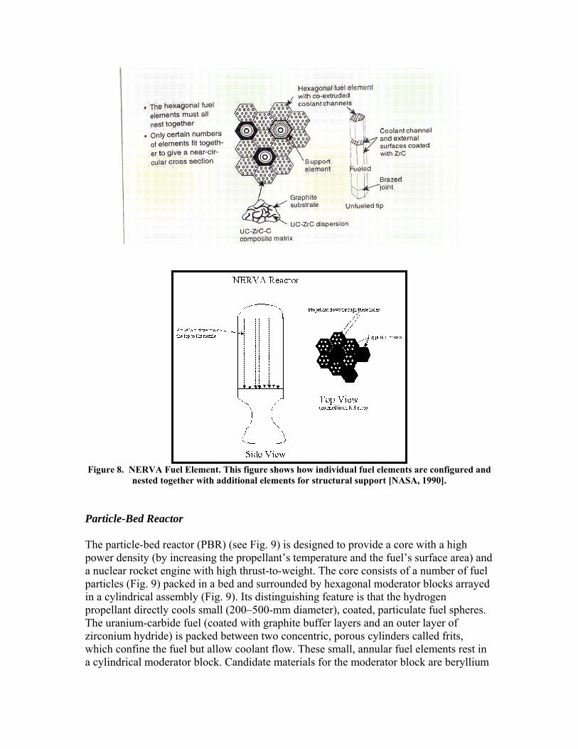
Figure 8. NERVA Fuel Element. This figure shows how individual fuel elements are configured and
nested together with additional elements for structural support [NASA, 1990].
Particle-Bed Reactor The particle-bed reactor (PBR) (see Fig. 9) is designed to provide a core with a high power density (by increasing the propellant’s temperature and the fuel’s surface area) and a nuclear rocket engine with high thrust-to-weight. The core consists of a number of fuel particles (Fig. 9) packed in a bed and surrounded by hexagonal moderator blocks arrayed in a cylindrical assembly (Fig. 9). Its distinguishing feature is that the hydrogen propellant directly cools small (200–500-mm diameter), coated, particulate fuel spheres. The uranium-carbide fuel (coated with graphite buffer layers and an outer layer of zirconium hydride) is packed between two concentric, porous cylinders called frits, which confine the fuel but allow coolant flow. These small, annular fuel elements rest in a cylindrical moderator block. Candidate materials for the moderator block are beryllium
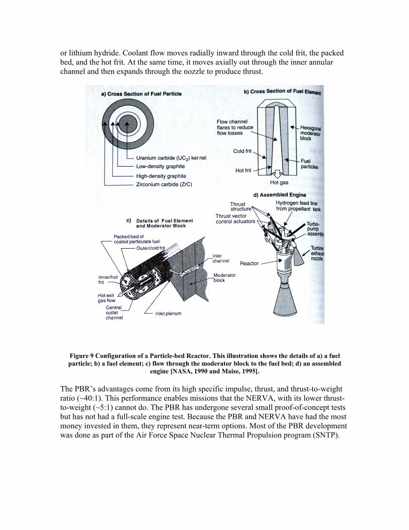
or lithium hydride. Coolant flow moves radially inward through the cold frit, the packed bed, and the hot frit. At the same time, it moves axially out through the inner annular channel and then expands through the nozzle to produce thrust.
Figure 9 Configuration of a Particle-bed Reactor. This illustration shows the details of a) a fuel particle; b) a fuel element; c) flow through the moderator block to the fuel bed; d) an assembled
engine [NASA, 1990 and Maise, 1995]. The PBR’s advantages come from its high specific impulse, thrust, and thrust-to-weight ratio (~40:1). This performance enables missions that the NERVA, with its lower thrust-to-weight (~5:1) cannot do. The PBR has undergone several small proof-of-concept tests but has not had a full-scale engine test. Because the PBR and NERVA have had the most money invested in them, they represent near-term options. Most of the PBR development was done as part of the Air Force Space Nuclear Thermal Propulsion program (SNTP).
This program lasted until 1993, with a budget of about $40 million per year. It intended to design a particle-bed reactor for various Air Force missions, but it ended having achieved:
-Fuel tests to temperatures as high as 3000 K (NERVA only reached 2650 K) -Nuclear tests of single fuel elements -Criticality experiments for a prototype 1000-MW core -Tests of thermal hydraulics in multiple fuel elements at high power densities (40 MW/liter as compared to about 2 MW/liter for NERVA) -Various mission designs (detailed analysis of a stage for a mission to Mars) -Verification of computer codes for simulating reactor physics
CERMET The CERMET-core nuclear rocket (see Fig. 10) uses a fast fissioning spectrum (greater than 1 MeV) compared to thermal reactors that slow down neutrons to fission energies of less than 1eV. Therefore, it does not need a moderator. The CERMET has a lower thrust-to-weight than the particle bed and has not been tested as extensively as the NERVA-type engines. Fuel tests show the CERMET-type fuel is much more robust than that for either NERVA or PBR. This feature makes CERMET attractive for applications such as a reusable orbital-transfer vehicle (OTV), for which we may need as many as 50 burns. The reactor consists of hexagonal fuel elements similar to those in the NERVA design, except that the fuel is made of uranium-dioxide particles imbedded in a tungsten or tungsten/rhenium matrix. The advantages of CERMET fuel are its potential for very long operating life (more than 40 hours), ability to restart, handling of temperature cycling at high temperature, and greater compatibility between the fuel and hydrogen coolant (resulting in high fuel integrity and retention of fission products). However, the metal matrix can increase system mass because of competition for neutron absorption in uranium and tungsten. Using an axial, two-zone fuel element reduces system mass. In this two-zone concept, the fuel loading in the upper (low-temperature) half of the core uses a molybdenum/urania matrix configuration. The lower (high-temperature) part of the core uses a tungsten-rhenium/urania matrix configuration. This concept reduces the system’s mass and gives it a thrust-to-weight ratio of 5.3:1—slightly better than NERVA. The system, shown in Fig. 10, consists of a CERMET core surrounded by a cooled pressure-containment shell. A neutron reflector and reactivity-control assembly mounts to the outside of the pressure vessel. So far, tests of the CERMET have checked only the fuel—up to 1900 K for 10,000 hours.
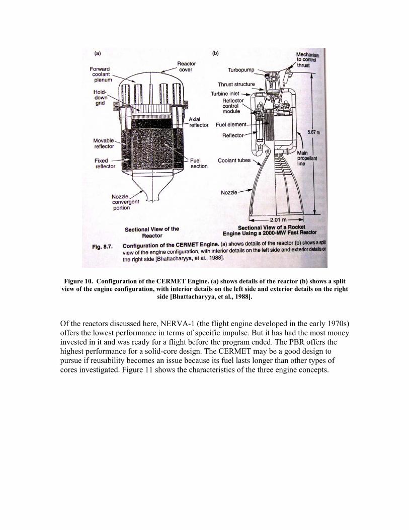
Figure 10. Configuration of the CERMET Engine. (a) shows details of the reactor (b) shows a split view of the engine configuration, with interior details on the left side and exterior details on the right
side [Bhattacharyya, et al., 1988]. Of the reactors discussed here, NERVA-1 (the flight engine developed in the early 1970s) offers the lowest performance in terms of specific impulse. But it has had the most money invested in it and was ready for a flight before the program ended. The PBR offers the highest performance for a solid-core design. The CERMET may be a good design to pursue if reusability becomes an issue because its fuel lasts longer than other types of cores investigated. Figure 11 shows the characteristics of the three engine concepts.
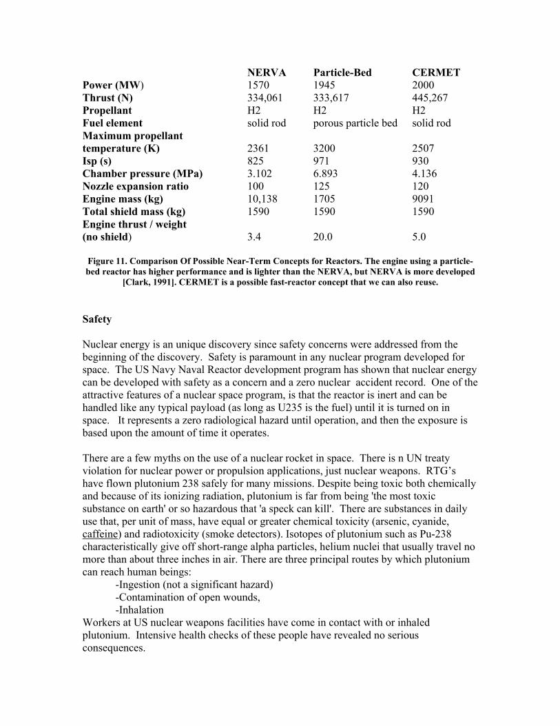
NERVA Particle-Bed CERMET Power (MW) 1570 1945 2000 Thrust (N) 334,061 333,617 445,267 Propellant H2 H2 H2 Fuel element solid rod porous particle bed solid rod Maximum propellant temperature (K) 2361 3200 2507 Isp (s) 825 971 930 Chamber pressure (MPa) 3.102 6.893 4.136 Nozzle expansion ratio 100 125 120 Engine mass (kg) 10,138 1705 9091 Total shield mass (kg) 1590 1590 1590 Engine thrust / weight (no shield) 3.4 20.0 5.0
Figure 11. Comparison Of Possible Near-Term Concepts for Reactors. The engine using a particle-bed reactor has higher performance and is lighter than the NERVA, but NERVA is more developed
[Clark, 1991]. CERMET is a possible fast-reactor concept that we can also reuse. Safety Nuclear energy is an unique discovery since safety concerns were addressed from the beginning of the discovery. Safety is paramount in any nuclear program developed for space. The US Navy Naval Reactor development program has shown that nuclear energy can be developed with safety as a concern and a zero nuclear accident record. One of the attractive features of a nuclear space program, is that the reactor is inert and can be handled like any typical payload (as long as U235 is the fuel) until it is turned on in space. It represents a zero radiological hazard until operation, and then the exposure is based upon the amount of time it operates. There are a few myths on the use of a nuclear rocket in space. There is n UN treaty violation for nuclear power or propulsion applications, just nuclear weapons. RTG’s have flown plutonium 238 safely for many missions. Despite being toxic both chemically and because of its ionizing radiation, plutonium is far from being 'the most toxic substance on earth' or so hazardous that 'a speck can kill'. There are substances in daily use that, per unit of mass, have equal or greater chemical toxicity (arsenic, cyanide, caffeine) and radiotoxicity (smoke detectors). Isotopes of plutonium such as Pu-238 characteristically give off short-range alpha particles, helium nuclei that usually travel no more than about three inches in air. There are three principal routes by which plutonium can reach human beings:
-Ingestion (not a significant hazard) -Contamination of open wounds, -Inhalation
Workers at US nuclear weapons facilities have come in contact with or inhaled plutonium. Intensive health checks of these people have revealed no serious consequences.
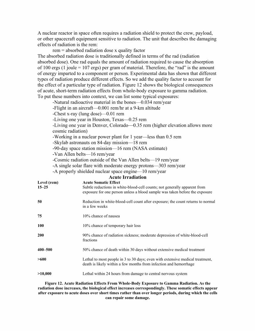
A nuclear reactor in space often requires a radiation shield to protect the crew, payload, or other spacecraft equipment sensitive to radiation. The unit that describes the damaging effects of radiation is the rem:
rem = absorbed radiation dose x quality factor The absorbed radiation dose is traditionally defined in terms of the rad (radiation absorbed dose). One rad equals the amount of radiation required to cause the absorption of 100 ergs (1 joule = 107 ergs) per gram of material. Therefore, the “rad” is the amount of energy imparted to a component or person. Experimental data has shown that different types of radiation produce different effects. So we add the quality factor to account for the effect of a particular type of radiation. Figure 12 shows the biological consequences of acute, short-term radiation effects from whole-body exposure to gamma radiation. To put these numbers into context, we can list some typical exposures:
-Natural radioactive material in the bones—0.034 rem/year -Flight in an aircraft—0.001 rem/hr at a 9-km altitude -Chest x-ray (lung dose)—0.01 rem -Living one year in Houston, Texas—0.25 rem -Living one year in Denver, Colorado—0.35 rem (higher elevation allows more cosmic radiation) -Working in a nuclear power plant for 1 year—less than 0.5 rem -Skylab astronauts on 84-day mission—18 rem -90-day space station mission—16 rem (NASA estimate) -Van Allen belts—16 rem/year -Cosmic radiation outside of the Van Allen belts—19 rem/year -A single solar flare with moderate energy protons—303 rem/year -A properly shielded nuclear space engine—10 rem/year
Acute Irradiation Level (rem) Acute Somatic Effect 15–25 Subtle reductions in white-blood-cell counts; not generally apparent from
exposure for one person unless a blood sample was taken before the exposure 50 Reduction in white-blood-cell count after exposure; the count returns to normal
in a few weeks 75 10% chance of nausea 100 10% chance of temporary hair loss 200 90% chance of radiation sickness; moderate depression of white-blood-cell
fractions 400–500 50% chance of death within 30 days without extensive medical treatment >600 Lethal to most people in 3 to 30 days; even with extensive medical treatment,
death is likely within a few months from infection and hemorrhage >10,000 Lethal within 24 hours from damage to central nervous system
Figure 12. Acute Radiation Effects From Whole-Body Exposure to Gamma Radiation. As the radiation dose increases, the biological effect increases correspondingly. These somatic effects appear after exposure to acute doses over short times rather than over longer periods, during which the cells
can repair some damage.
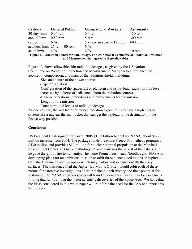
Criteria General Public Occupational Workers Astronauts 30-day limit 0.04 rem 0.4 rem 150 rem annual limit 0.50 rem 5 rem 300 rem career limit N/A 5 x (age in years – 18) rem 600 rem accident limit 25 rem 100 rem N/A acute limit N/A N/A 10 rem Figure 13. Allowable Limits for Skin Dosage. The US National Committee on Radiation Protection
and Measurement has agreed to these allowables. Figure 13 shows allowable skin radiation dosages, as given by the US National Committee on Radiation Protection and Measurement. Many factors influence the geometry, composition, and mass of the radiation shield, including:
-Size and nature of the power source -Type of radiation -Configuration of the spacecraft or platform and its payload (radiation flux level decreases by a factor of 1/distance2 from the radiation source) -Generic operational procedures and requirements for the mission -Length of the mission -Total permitted levels of radiation dosage
As one key see, the key factor to reduce radiation exposure, is to have a high energy system like a nuclear thermal rocket that can get the payload to the destination in the fastest way possible. Conclusion US President Bush signed into law a 2005 $16.2 billion budget for NASA, about $822 million increase from 2004. The package funds the entire Project Prometheus program at $430 million and provides $10 million for nuclear thermal propulsion at the Marshall Space Flight Center. In Greek mythology, Prometheus was the wisest of the Titans, and he gave the gift of fire to humanity. The name Prometheus means 'forethought. NASA is developing plans for an ambitious mission to orbit three planet-sized moons of Jupiter -- Callisto, Ganymede and Europa -- which may harbor vast oceans beneath their icy surfaces. The mission, called the Jupiter Icy Moons Orbiter, would orbit each of these moons for extensive investigations of their makeup, their history and their potential for sustaining life. NASA's Galileo spacecraft found evidence for these subsurface oceans, a finding that ranks among the major scientific discoveries of the Space Age. We hope that the ideas considered in this white paper will reinforce the need for the IAA to support this technology.
References Angelo, Joseph and Buden, David. 1985. Space Nuclear Power. Malabar, Florida: Orbit Book Company, a division of Krieger Publishing Company. Benedict, M. and Pigford, T.H. 1957. Nuclear Chemical Engineering. New York, NY: McGraw-Hill Book Company. Bhattacharyya, Samit et al. 1988. CERMET Reactor Orbit Transfer Vehicle Concept. AFAL-TR-88-033. Edwards AFB, CA: U.S. Air Force Astronautics Laboratory. Clark, John S. 1991. An Historical Collection of Papers on Nuclear Thermal Propulsion. Washington D.C.: American Institute of Aeronautics and Astronautics. Drake, M.K. 1970. Data Formats and Procedures for the ENDF Neutron Cross Section Library. BNL-50274 (T-601). Brookhaven National Laboratory. Henry, Allan F. 1986. Nuclear Reactor Analysis. Boston: MIT Press. Knief, Rolland Allen. 1992. Nuclear Engineering: Theory and Technology of Nuclear Power. Washington D.C.: Hemisphere Publishing. Los Alamos National Laboratory. 1986. Monte Carlo Neutron/Photon Transport Code. Los Alamos, New Mexico. Ludewig, Hans. 1993. Summary of Particle Bed Reactor Designs for the Space Nuclear Thermal Propulsion Program. BNL-52408. Brookhaven National Laboratory. Maise, George, and Hans Ludewig. 1995. Brookhaven National Laboratory. Private communication. Ma, I. 1983. Materials for Nuclear Applications. New York: McGraw Hill. NASA. 1990. NASA/DOD/DOE Nuclear Thermal Propulsion Workshop Notebook. Cleveland Ohio: NASA Lewis Research Center. Witter, Jonathan Keay. April,1993. Modeling for the Simulation and Control of Nuclear Reactor Rocket Systems. Thesis, Massachusetts Institute of Technology.