number: 280simpson strong-tie company inc. 5956 west las positas boulevard pleasanton, ca 94588...
TRANSCRIPT

Number: 280
Originally Issued: 01/18/2013 Revised: 03/14/2019 Valid Through: 01/31/2020
The product described in this Uniform Evaluation Service (UES) Report has been evaluated as an alternative material, design or method of construction in order to satisfy and comply with the intent of the provision of the code, as noted in this report, and for at least equivalence to that prescribed in the code in quality, strength, effectiveness, fire resistance, durability and safely, as applicable, in accordance with IBC Section 104.11. This document shall only be reproduced in its entirety.
Copyright © 2019 by International Association of Plumbing and Mechanical Officials. All rights reserved. Printed in the United States. Ph: 1-877-4IESRPT • Fax: 909.472.4171 web: www.uniform-es.org • 4755 East Philadelphia Street, Ontario, California 91761-2816 – USA
Page 1 of 23
Simpson Strong-Tie Company Inc.
5956 West Las Positas Boulevard
Pleasanton, CA 94588
(800) 999-5099
www.strongtie.com
SIMPSON STRONG-TIE® MISCELLANEOUS
CONNECTORS
CSI Division: 06—WOOD, PLASTIC, and
COMPOSITES
CSI Section: 06 05 23—Wood, Plastic, and Composite
Fastenings
1.0 SCOPE OF EVALUATION
1.1 Compliance to the following codes & regulations:
• 2018, 2015, 2012, 2009 and 2006 International
Building Code® (IBC)
• 2018, 2015, 2012, 2009 and 2006 International
Residential Code® (IRC)
• 2017 City of Los Angeles Building Code (LABC) -
attached Supplement
• 2017 City of Los Angeles Residential Code (LARC)
- attached Supplement
1.2 Evaluated in accordance with:
• IAPMO UES EC 002-2018
• ICC-ES AC13
1.3 Properties assessed:
• Structural
2.0 PRODUCT USE
Simpson Strong-Tie® miscellaneous connectors are used as
wood framing connectors in accordance with Section
2304.9.3 of the IBC. The products may be used in structures
regulated under the IRC when an engineered design is
submitted in accordance with Section R301.1.3 of the IRC.
3.0 PRODUCT DESCRIPTION
3.1 Product Information
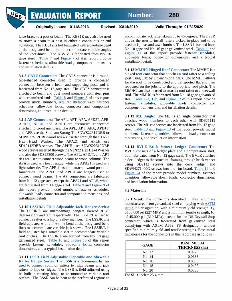
3.1.1 RTC Rigid Tie Connectors Series: The RTC Rigid
Tie connectors are used to attach two horizontal wood joist
members to a vertical post forming a 90-degree corner. The
RTC22Z, RTC2Z and RTC42 are fabricated from No. 18
gage steel, and the RTC44 is fabricated from No. 14 gage
steel. Table 1 and Figure 1 of this report provide required
member sizes, fastener schedules, allowable loads,
connector dimensions, and a typical installation detail.
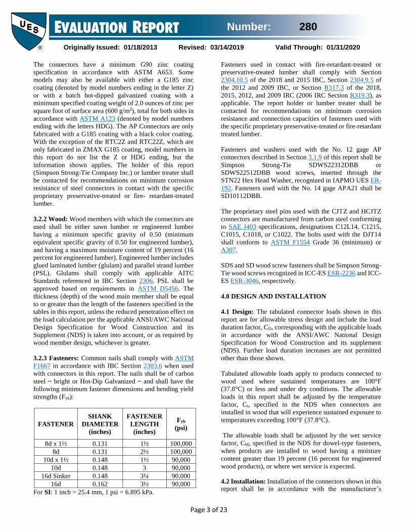
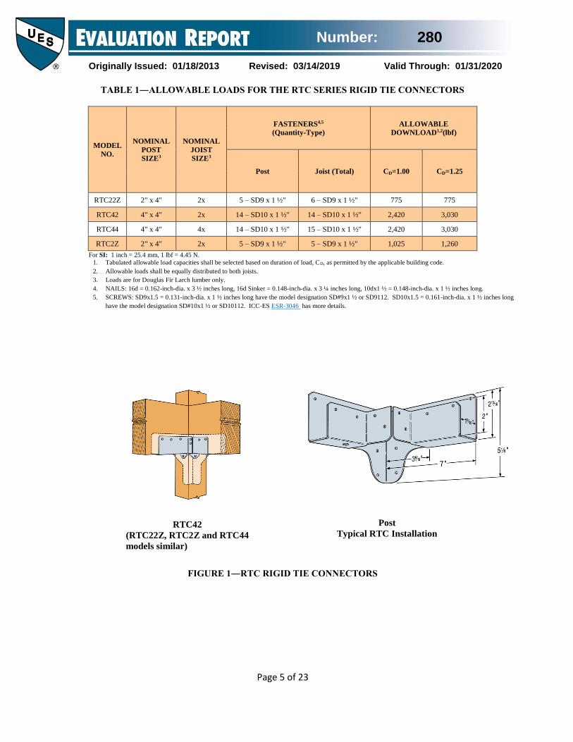
3.1.2 LSCZ Adjustable Stringer Connector: The LSCZ
adjustable stringer connector is a concealed connector used
to attach a stair stringer to a supporting header or rim joist.
The LSCZ is field-adjusted with a one-time bend at the
designated bend line to accommodate variable stair stringer
pitches. The LSCZ may be used with either solid or notched
stair stringers. The LSCZ is fabricated from No. 18 gage
steel. Table 2 and Figure 2 of this report provide required
member sizes, fastener schedules, allowable loads,
connector dimensions, and installation details.
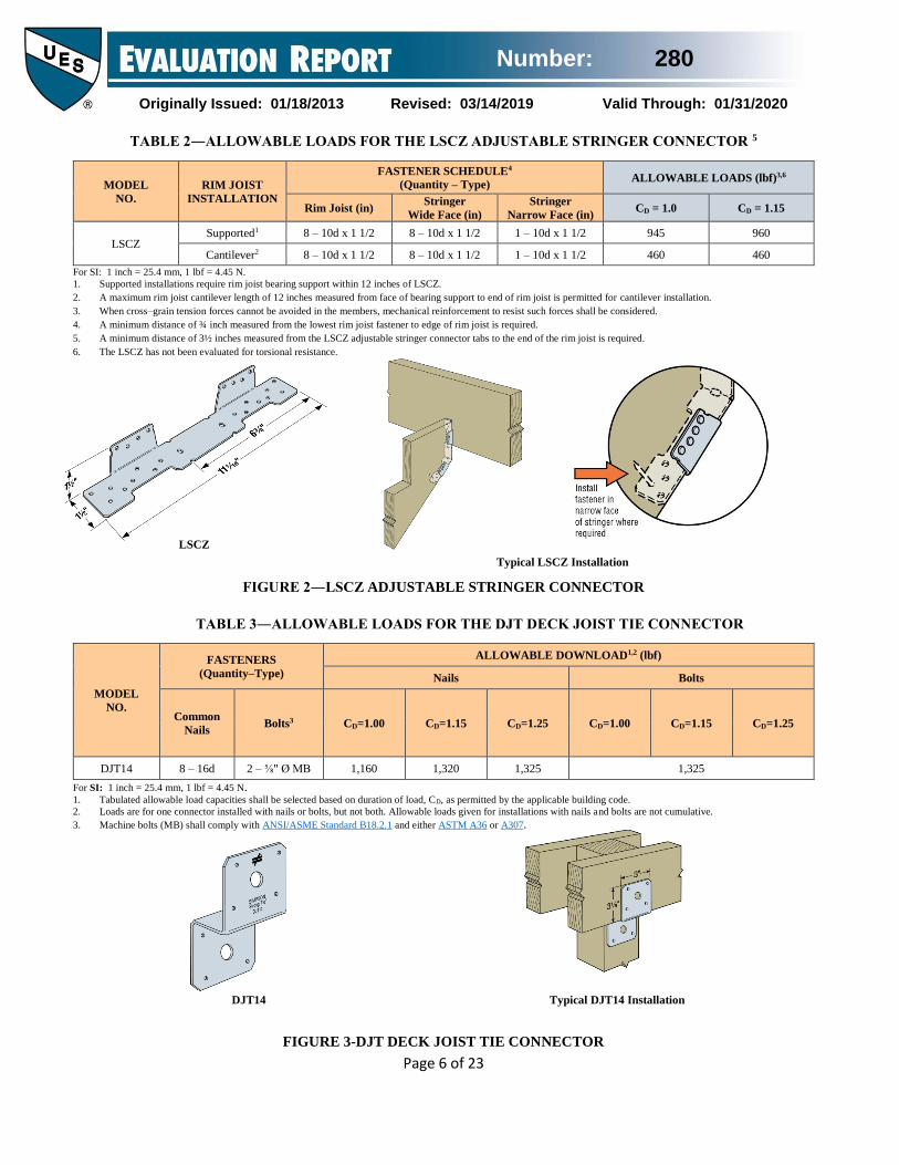
3.1.3 DJT14 Deck Joist Tie: DJT14 Deck Joist Tie
connector is used to attach joists to posts and is fabricated
from No. 14 gage steel. Table 3 and Figure 3 of this report
provide fastener schedules, allowable loads, connector
dimensions, and a typical installation detail.
3.1.4 CJTZ and HCJTZ Connectors: The CJTZ and
HCJTZ connectors are T-shaped connectors used to provide
a concealed connection between a joist and supporting
header or post. The CJTZ is fabricated from No. 12 gage
steel. The HCJTZ is fabricated from No. 10 gage steel. The
CJTZ and HCJTZ connectors are attached to a supporting
wood member with SDS wood screws and to the routed end
of a joist using steel pins with chamfered ends. Table 4 and
Figure 4 of this report provide model numbers, required
member sizes, fastener schedules, allowable loads,
connector and component dimensions, and installation
details.
3.1.5 DS Drywall Stops: The DS Drywall Stops are used as
backing support for gypsum wallboard edges at wall corners
and wall ceiling intersections and is fabricated from No. 20
gage steel. Use of the DS Drywall Stops is limited to non-
fire-resistance-rated construction and to nonstructural
applications. The DS Drywall Stops shall not be used in wall
construction designated as braced wall panels conforming to
Section 2308.6 of the 2018 and 2015 IBC, Section 2308.9.3
of the 2012 IBC, Section R602.10.1 of the 2018, 2015, and
2012 IRC, Section R602.10.1.1 of the 2009 IRC, or Section
R602.10.3 of the 2006 IRC. Table 5 and Figure 5 of this
report provide fastener and spacing schedules, connector
dimensions and a typical installation detail.
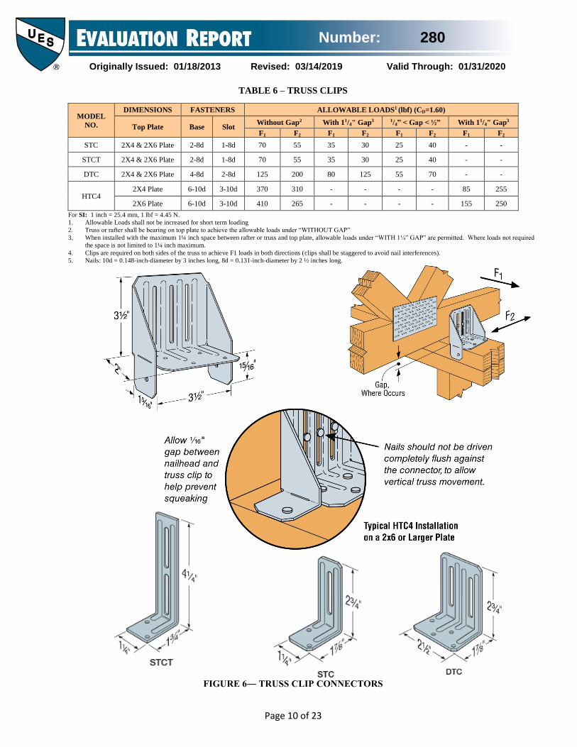
3.1.6 Truss Clips: STC, STCT, DTC, and HTC4 truss clips
are used as alignment control between a roof truss and a non-
gravity-load bearing walls. The 1½ inch-long (38.1 mm)
slots permit vertical truss chord movement. These
connectors are formed from No. 18 gage galvanized steel.
Figure 6 and Table 6 of this report provide dimensions,
required fasteners, and allowable loads.
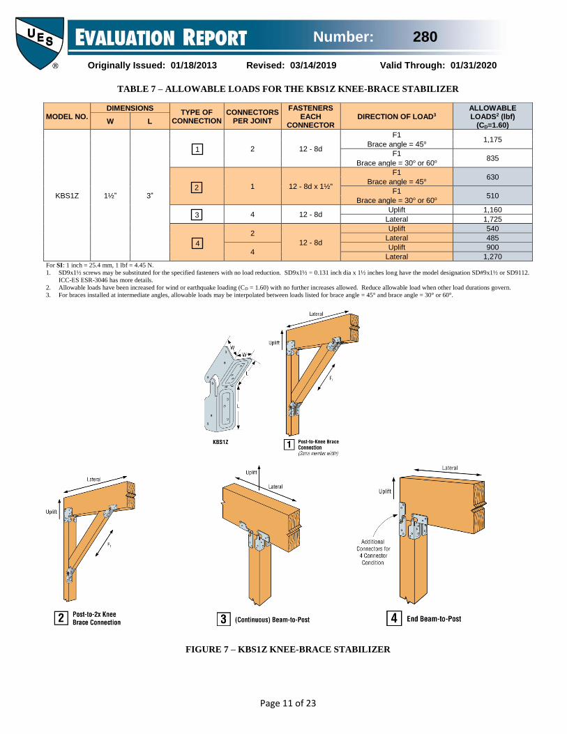
3.1.7 KBS1Z Knee-Brace Stabilizer: The KBS1Z knee-
brace stabilizer is an adjustable connector used to attach a
Number: 280
Originally Issued: 01/18/2013 Revised: 03/14/2019 Valid Through: 01/31/2020
Page 2 of 23
knee-brace to a post or beam. The KBS1Z may also be used
to attach a beam to a post in either a continuous or end
condition. The KBS1Z is field-adjusted with a one-time bend
at the designated bend line to accommodate variable angles
of the knee-brace. The KBS1Z is fabricated from No. 16
gage steel. Table 7 and Figure 7 of this report provide
fastener schedules, allowable loads, component dimensions
and installation details.
3.1.8 CBTZ Connector: The CBTZ connector is a round,
tube-shaped connector used to provide a concealed
connection between a beam and supporting post, and is
fabricated from No. 12 gage steel. The CBTZ connector is
attached to beam and post wood members with steel pins
with chamfered ends. Table 8 and Figure 8 of this report
provide model numbers, required member sizes, fastener
schedules, allowable loads, connector and component
dimensions, and installation details.
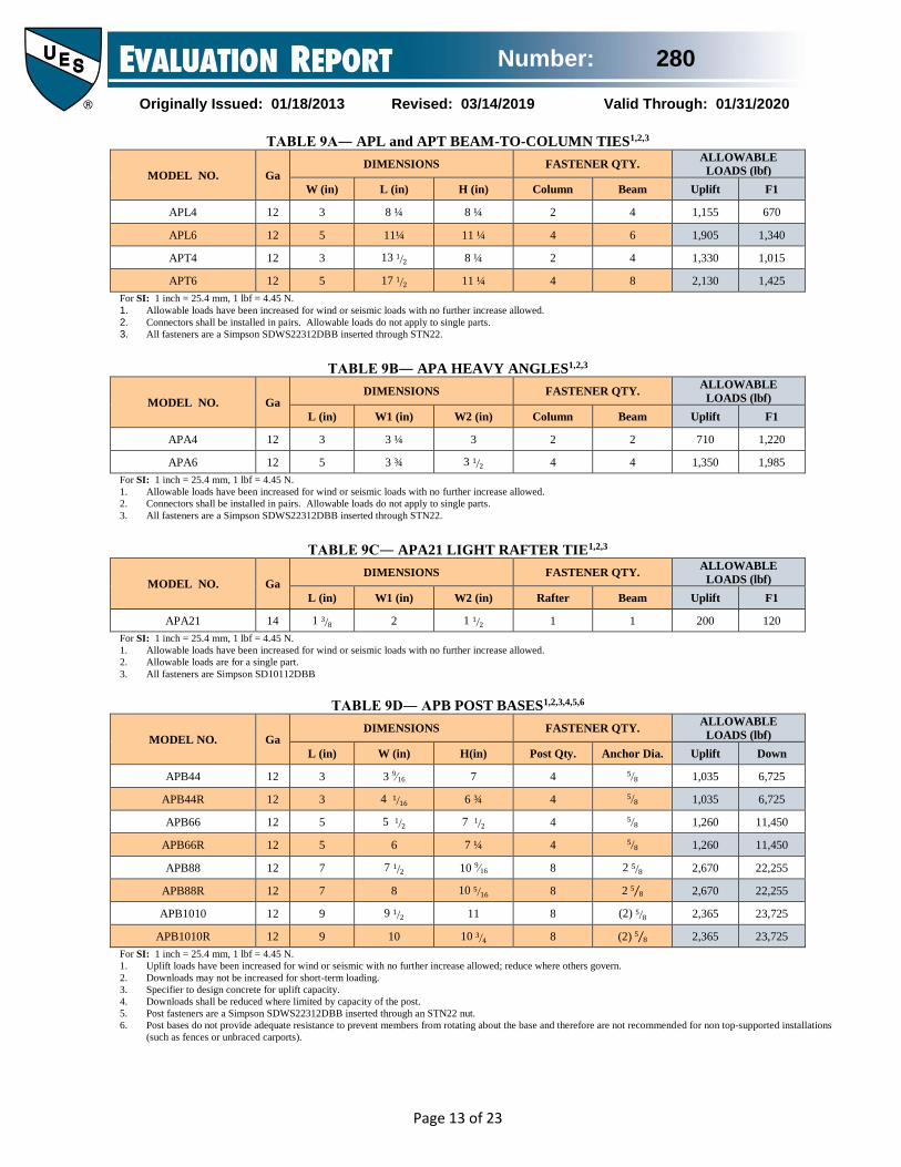
3.1.9 AP Connectors: The APL, APT, APA, APDJT, APB,
APA21, APLH, and APHH are decorative connectors
attached to wood members. The APL, APT, APA, APDJT,
and APB use the Simpson Strong-Tie SDWS22312DBB or
SDWS22512DBB wood screws inserted through the STN22
Hex Head Washer. The APA21 and APLH use
SD10112DBB screws. The APHH uses SDWS22312DBB
wood screws inserted through the STN22 Hex Head Washer
and also the SDS25300 screws. The APL, APDJT, and APT
ties are used to connect wood beams to wood columns. The
APA is used as a heavy angle, while the APA21 is used as a
light rafter tie. The APB is used to attach a wood post to a
foundation. The APLH and APHH are hangers used to
connect wood beams. The AP connectors are fabricated
from No. 12 gage steel, except the APA21 and APLH, which
are fabricated from 14 gage steel. Table 9 and Figure 9 of
this report provide model numbers, fastener schedules,
allowable loads, connector and component dimensions, and
installation details.
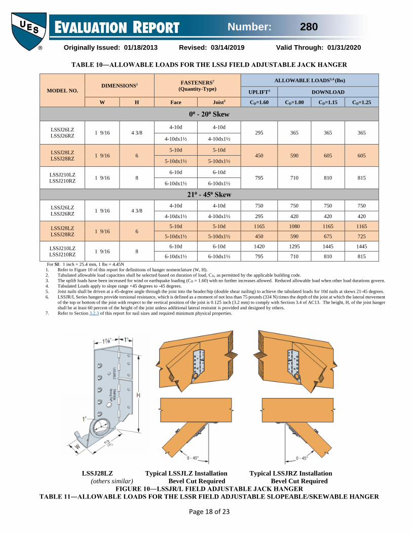
3.1.10 LSSJR/L Field Adjustable Jack Hanger Series: The LSSJR/L are mirror-image hangers skewed at 45 degrees right and left, respectively. The LSSJR/L is used to connect a rafter to a hip or valley member. The LSSJR/L is field-adjusted with a one-time bend at the designated bend lines to accommodate variable jack skews. The LSSJR/L is field-adjusted by a rotatable seat to accommodate variable roof pitches. The LSSJR/L are formed from No. 18 gage galvanized steel. Table 10 and Figure 10 of this report provide fastener schedules, allowable loads, connector dimensions, and a typical installation detail.
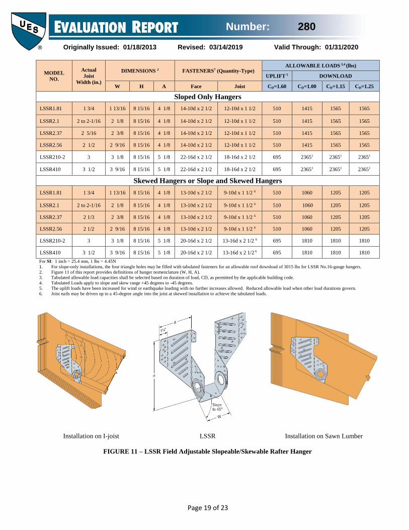
3.1.11 LSSR Field Adjustable Slopeable and Skewable Rafter Hanger Series: The LSSR is a face-mount hanger used to connect common rafters to ridge beams and jack rafters to hips or ridges. The LSSR is field-adjusted using its built-in rotating hinge to accommodate variable roof pitches. The LSSR can be bent at the perforated regions to
accommodate jack rafter skews up to 45 degrees. The LSSR allows the user to install rafters tacked in-place and to be used on I-joists and sawn lumber. The LSSR is formed from No. 18 gage and No. 16 gage galvanized steel. Table 11 and Figure 11 of this report provide fastener schedules, allowable loads, connector dimensions, and a typical installation detail.
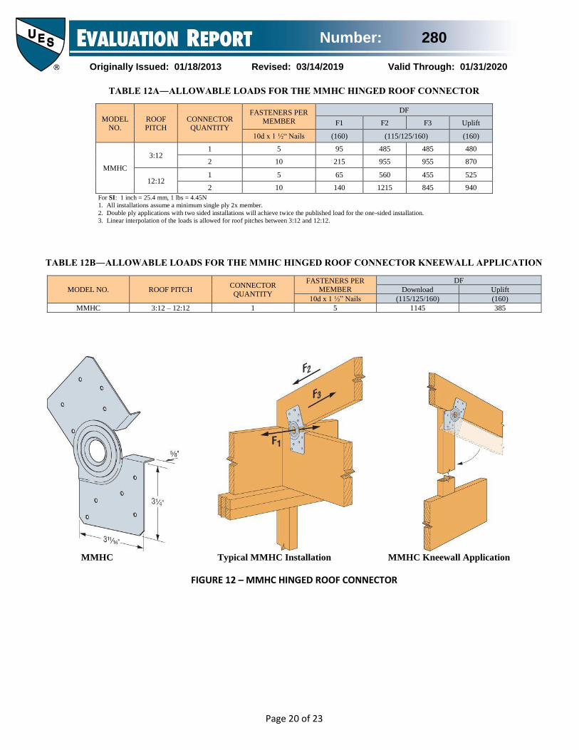
3.1.12 MMHC Hinged Roof Connector: The MMHC is a hinged roof connector that attaches a roof rafter to a ceiling joist using 10d by 1½-inch-long nails. The MMHC allows for the roof to be constructed and transported flat and then reopened on the jobsite to the appropriate roof pitch. The MMHC can also be used to attach a roof rafter to a kneewall stud. The MMHC is fabricated from No. 18 gage galvanized steel. Table 12a, 12b, and Figure 12 of this report provide fastener schedules, allowable loads, connector and component dimensions, and installation details.
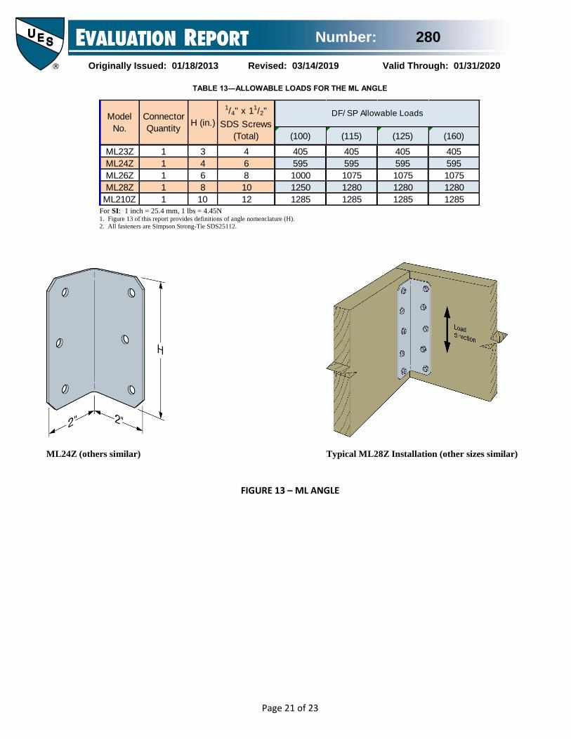
3.1.13 ML Angle: The ML is an angle connector that
attaches wood members to each other with SDS25112
screws. The ML connectors are fabricated from No. 12 gage
steel. Table 13 and Figure 13 of the report provide model
numbers, fastener quantities, allowable loads, connector
dimensions, and installation information.
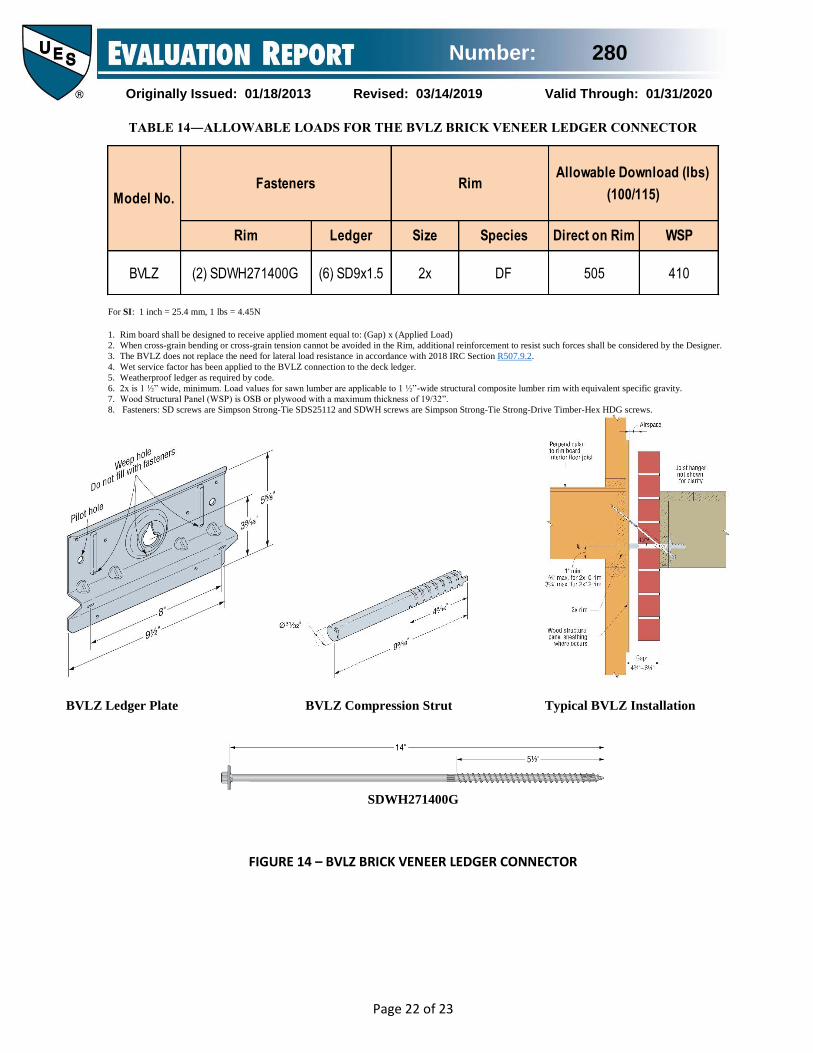
3.1.14 BVLZ Brick Veneer Ledger Connector: The
BVLZ consists of a ledger plate and a compression strut,
both fabricated from No. 12 gage steel. The BVLZ attaches
a deck ledger to the structural framing through brick veneer
using SD9112 screws into the deck ledger and
SDWH271400G screws into the rim board. Table 14 and
Figure 14 of the report provide model numbers, fastener
quantities, allowable down loads, connector dimensions,
and installation information.
3.2 Materials
3.2.1 Steel: The connectors described in this report are
manufactured from galvanized steel complying with ASTM
A653, SS designation, with a minimum yield strength, Fy,
of 33,000 psi (227 MPa) and a minimum tensile strength, Fu,
of 45,000 psi (310 MPa), except for the DS Drywall Stop
connector, which is fabricated from galvanized steel
complying with ASTM A653, FS designation, without
specified minimum yield and tensile strengths. Base metal
thicknesses for the connectors in this report are as follows:
GAGE BASE METAL
THICKNESS (in.)
No. 12 0.0975
No. 14 0.0685
No. 16 0.0555
No. 18 0.0455
No. 20 0.0335
For SI: 1 inch = 25.4 mm
Number: 280
Originally Issued: 01/18/2013 Revised: 03/14/2019 Valid Through: 01/31/2020
Page 3 of 23
The connectors have a minimum G90 zinc coating
specification in accordance with ASTM A653. Some
models may also be available with either a G185 zinc
coating (denoted by model numbers ending in the letter Z)
or with a batch hot-dipped galvanized coating with a
minimum specified coating weight of 2.0 ounces of zinc per
square foot of surface area (600 g/m2), total for both sides in
accordance with ASTM A123 (denoted by model numbers
ending with the letters HDG). The AP Connectors are only
fabricated with a G185 coating with a black color coating.
With the exception of the RTC2Z and RTC22Z, which are
only fabricated in ZMAX G185 coating, model numbers in
this report do not list the Z or HDG ending, but the
information shown applies. The holder of this report
(Simpson Strong-Tie Company Inc.) or lumber treater shall
be contacted for recommendations on minimum corrosion
resistance of steel connectors in contact with the specific
proprietary preservative-treated or fire- retardant-treated
lumber.
3.2.2 Wood: Wood members with which the connectors are
used shall be either sawn lumber or engineered lumber
having a minimum specific gravity of 0.50 (minimum
equivalent specific gravity of 0.50 for engineered lumber),
and having a maximum moisture content of 19 percent (16
percent for engineered lumber). Engineered lumber includes
glued laminated lumber (glulam) and parallel strand lumber
(PSL). Glulams shall comply with applicable AITC
Standards referenced in IBC Section 2306. PSL shall be
approved based on requirements in ASTM D5456. The
thickness (depth) of the wood main member shall be equal
to or greater than the length of the fasteners specified in the
tables in this report, unless the reduced penetration effect on
the load calculation per the applicable ANSI/AWC National
Design Specification for Wood Construction and its
Supplement (NDS) is taken into account, or as required by
wood member design, whichever is greater.
3.2.3 Fasteners: Common nails shall comply with ASTM
F1667 in accordance with IBC Section 2303.6 when used
with connectors in this report. The nails shall be of carbon
steel − bright or Hot-Dip Galvanized − and shall have the
following minimum fastener dimensions and bending yield
strengths (Fyb):
FASTENER
SHANK
DIAMETER
(inches)
FASTENER
LENGTH
(inches)
Fyb
(psi)
8d x 1½ 0.131 1½ 100,000
8d 0.131 2½ 100,000
10d x 1½ 0.148 1½ 90,000
10d 0.148 3 90,000
16d Sinker 0.148 3¼ 90,000
16d 0.162 3½ 90,000
For SI: 1 inch = 25.4 mm, 1 psi = 6.895 kPa.
Fasteners used in contact with fire-retardant-treated or
preservative-treated lumber shall comply with Section
2304.10.5 of the 2018 and 2015 IBC, Section 2304.9.5 of
the 2012 and 2009 IBC, or Section R317.3 of the 2018,
2015, 2012, and 2009 IRC (2006 IRC Section R319.3), as
applicable. The report holder or lumber treater shall be
contacted for recommendations on minimum corrosion
resistance and connection capacities of fasteners used with
the specific proprietary preservative-treated or fire-retardant
treated lumber.
Fasteners and washers used with the No. 12 gage AP
connectors described in Section 3.1.9 of this report shall be
Simpson Strong-Tie SDWS22312DBB or
SDWS22512DBB wood screws, inserted through the
STN22 Hex Head Washer, recognized in IAPMO UES ER-
192. Fasteners used with the No. 14 gage APA21 shall be
SD10112DBB.
The proprietary steel pins used with the CJTZ and HCJTZ
connectors are manufactured from carbon steel conforming
to SAE J403 specifications, designations C12L14, C1215,
C1015, C1018, or C1022. The bolts used with the DJT14
shall conform to ASTM F1554 Grade 36 (minimum) or
A307.
SDS and SD wood screw fasteners shall be Simpson Strong-
Tie wood screws recognized in ICC-ES ESR-2236 and ICC-
ES ESR-3046, respectively.
4.0 DESIGN AND INSTALLATION
4.1 Design: The tabulated connector loads shown in this
report are for allowable stress design and include the load
duration factor, CD, corresponding with the applicable loads
in accordance with the ANSI/AWC National Design
Specification for Wood Construction and its supplement
(NDS). Further load duration increases are not permitted
other than those shown.
Tabulated allowable loads apply to products connected to
wood used where sustained temperatures are 100°F
(37.8°C) or less and under dry conditions. The allowable
loads in this report shall be adjusted by the temperature
factor, Ct, specified in the NDS when connectors are
installed in wood that will experience sustained exposure to
temperatures exceeding 100°F (37.8°C).
The allowable loads shall be adjusted by the wet service
factor, CM, specified in the NDS for dowel-type fasteners,
when products are installed to wood having a moisture
content greater than 19 percent (16 percent for engineered
wood products), or where wet service is expected.
4.2 Installation: Installation of the connectors shown in this report shall be in accordance with the manufacturer’s

Number: 280
Originally Issued: 01/18/2013 Revised: 03/14/2019 Valid Through: 01/31/2020
Page 4 of 23
published installation instructions and this evaluation report. If there is a conflict between this report and the manufacturer’s published installation instructions, the more restrictive shall govern.
5.0 LIMITATIONS
The Simpson Strong-Tie products described in this report
are in compliance with, or are acceptable alternatives to
what is specified in those codes listed in Section 1.0 of this
report subject to the following conditions:
5.1 The connectors shall be manufactured, identified and
installed in accordance with the manufacturer’s published
installation instructions and this report. A copy of the
instructions shall be available at the jobsite continuously
during installation.
5.2 Calculations and details showing compliance with this
report shall be submitted to the code official. No further
duration of load increase for earthquake or wind loading is
allowed except where already shown in the load tables. The
calculations and details shall be prepared by a registered
design professional where required by the statutes of the
jurisdiction in which the project is to be constructed.
5.3 Where applicable, adjustment factors noted in Section
4.1 of this report and the applicable codes shall be
considered.
5.4 Fasteners and connected wood members shall be in
compliance, respectively, with Sections 3.2.3 and 3.2.2 of
this report.
5.5 Use of connectors with fire-retardant-treated or
preservative-treated lumber shall be in accordance with
Section 3.2.1 of this report. Use of fasteners with fire-
retardant-treated or preservative-treated lumber shall be in
accordance with Section 3.2.3 of this report.
6.0 SUBSTANTIATING DATA
6.1 Data in accordance with IAPMO UES Evaluation
Criteria for the Testing and Analysis of Joist Hangers and
Miscellaneous Connectors (EC 002-2018), inclusive of tests
and calculations.
6.2 Data in accordance with Section 3.4 of ICC-ES Acceptance Criteria for Joist Hangers and Similar Devices (AC13), dated October 2018.
7.0 IDENTIFICATION
The products described in this report are identified with a
die-stamped label indicating the name of the manufacturer
(Simpson Strong-Tie), the model number, and the number
of the index evaluation report (ER-102), which identifies
products recognized in this report. The SD9, SD10 and
SDS wood screws are identified as described in evaluation
reports ICC-ES ESR-3046 and ICC-ES ESR-2236,
respectively.
or
IAPMO UES ER-280
Brian Gerber, P.E., S.E.
Vice President, Technical Operations
Uniform Evaluation Service
Richard Beck, PE, CBO, MCP
Vice President, Uniform Evaluation Service
GP Russ Chaney
CEO, The IAPMO Group
For additional information about this evaluation report please visit
www.uniform-es.org or email at info@uniform-es
Number: 280
Originally Issued: 01/18/2013 Revised: 03/14/2019 Valid Through: 01/31/2020
Page 5 of 23
TABLE 1―ALLOWABLE LOADS FOR THE RTC SERIES RIGID TIE CONNECTORS
MODEL
NO.
NOMINAL
POST
SIZE3
NOMINAL
JOIST
SIZE3
FASTENERS4,5
(Quantity-Type)
ALLOWABLE
DOWNLOAD1,2(lbf)
Post Joist (Total) CD=1.00 CD=1.25
RTC22Z 2" x 4" 2x 5 – SD9 x 1 ½" 6 – SD9 x 1 ½" 775 775
RTC42 4" x 4" 2x 14 – SD10 x 1 ½" 14 – SD10 x 1 ½" 2,420 3,030
RTC44 4" x 4" 4x 14 – SD10 x 1 ½" 15 – SD10 x 1 ½" 2,420 3,030
RTC2Z 2" x 4" 2x 5 – SD9 x 1 ½" 5 – SD9 x 1 ½" 1,025 1,260
For SI: 1 inch = 25.4 mm, 1 lbf = 4.45 N.
1. Tabulated allowable load capacities shall be selected based on duration of load, CD, as permitted by the applicable building code.
2. Allowable loads shall be equally distributed to both joists.
3. Loads are for Douglas Fir Larch lumber only.
4. NAILS: 16d = 0.162-inch-dia. x 3 ½ inches long, 16d Sinker = 0.148-inch-dia. x 3 ¼ inches long, 10dx1 ½ = 0.148-inch-dia. x 1 ½ inches long.
5. SCREWS: SD9x1.5 = 0.131-inch-dia. x 1 ½ inches long have the model designation SD#9x1 ½ or SD9112. SD10x1.5 = 0.161-inch-dia. x 1 ½ inches long
have the model designation SD#10x1 ½ or SD10112. ICC-ES ESR-3046 has more details.
FIGURE 1―RTC RIGID TIE CONNECTORS
RTC42
(RTC22Z, RTC2Z and RTC44
models similar)
Post
Typical RTC Installation
Number: 280
Originally Issued: 01/18/2013 Revised: 03/14/2019 Valid Through: 01/31/2020
Page 6 of 23
TABLE 2―ALLOWABLE LOADS FOR THE LSCZ ADJUSTABLE STRINGER CONNECTOR 5
MODEL
NO.
RIM JOIST
INSTALLATION
FASTENER SCHEDULE4
(Quantity – Type) ALLOWABLE LOADS (lbf)3,6
Rim Joist (in) Stringer
Wide Face (in)
Stringer
Narrow Face (in) CD = 1.0 CD = 1.15
LSCZ Supported1 8 – 10d x 1 1/2 8 – 10d x 1 1/2 1 – 10d x 1 1/2 945 960
Cantilever2 8 – 10d x 1 1/2 8 – 10d x 1 1/2 1 – 10d x 1 1/2 460 460
For SI: 1 inch = 25.4 mm, 1 lbf = 4.45 N.
1. Supported installations require rim joist bearing support within 12 inches of LSCZ.
2. A maximum rim joist cantilever length of 12 inches measured from face of bearing support to end of rim joist is permitted for cantilever installation.
3. When cross–grain tension forces cannot be avoided in the members, mechanical reinforcement to resist such forces shall be considered.
4. A minimum distance of ¾ inch measured from the lowest rim joist fastener to edge of rim joist is required.
5. A minimum distance of 3½ inches measured from the LSCZ adjustable stringer connector tabs to the end of the rim joist is required.
6. The LSCZ has not been evaluated for torsional resistance.
LSCZ
Typical LSCZ Installation
FIGURE 2―LSCZ ADJUSTABLE STRINGER CONNECTOR
TABLE 3―ALLOWABLE LOADS FOR THE DJT DECK JOIST TIE CONNECTOR
MODEL
NO.
FASTENERS
(Quantity–Type)
ALLOWABLE DOWNLOAD1,2 (lbf)
Nails Bolts
Common
Nails Bolts3 CD=1.00 CD=1.15 CD=1.25 CD=1.00 CD=1.15 CD=1.25
DJT14 8 – 16d 2 – ⅝" Ø MB 1,160 1,320 1,325 1,325
For SI: 1 inch = 25.4 mm, 1 lbf = 4.45 N. 1. Tabulated allowable load capacities shall be selected based on duration of load, CD, as permitted by the applicable building code.
2. Loads are for one connector installed with nails or bolts, but not both. Allowable loads given for installations with nails and bolts are not cumulative.
3. Machine bolts (MB) shall comply with ANSI/ASME Standard B18.2.1 and either ASTM A36 or A307.
DJT14 Typical DJT14 Installation
FIGURE 3-DJT DECK JOIST TIE CONNECTOR

Number: 280
Originally Issued: 01/18/2013 Revised: 03/14/2019 Valid Through: 01/31/2020
Page 7 of 23
TABLE 4―ALLOWABLE LOADS FOR THE CJTZ AND HCJTZ CONCEALED JOIST TIE CONNECTORS
MODEL
NO.
MIN.
JOIST
SIZE
DIMENSIONS FASTENERS
(Quantity–Type) ALLOWABLE LOADS1 (lbf)
H1 H2 Post2
(SDS)
Joist3
(Pins)
UPLIFT4 DOWNLOAD
CD=1.60 CD=1.00 CD=1.15 CD=1.25
DOUGLAS FIR–LARCH
CJT3Z 4 × 8 5 9∕16" 4 7∕16" 6 – SDS¼ × 3" 3 – ½" × 2 ¾" 1,540 1,730 1,730 1,730
3 – ½" × 4 ¾" 1,540 1,730 1,730 1,730
CJT4Z 4 × 10 7 5 15∕16" 8 – SDS¼ × 3" 4 – ½" × 2 ¾" 2,625 2,970 2,970 2,970
4 – ½" × 4 ¾" 2,625 2,970 2,970 2,970
CJT5Z 4 × 12 8 9∕16" 7 7∕16" 10 – SDS¼ × 3" 5 – ½" × 2 ¾" 3,160 3,935 4,520 4,580
5 – ½" × 4 ¾" 3,160 4,200 4,580 4,580
CJT6Z 4 × 12 10 8 15∕16" 12 – SDS¼ × 3" 6 – ½" × 2 ¾" 4,305 4,220 4,220 4,220
6 – ½" × 4 ¾" 4,305 4,220 4,220 4,220
HCJTZ 6 × 16 13 1∕16" 13 1∕16" 22 – SDS¼ × 3" 7 – ¾" × 4 ¾" 9,210 8,465 8,465 8,465
GLULAM5
CJT3Z 3⅛ × 7½ 5 9∕16" 4 7∕16" 6 – SDS¼ × 3" 3 – ½" × 2 ¾" 1,540 1,835 1,835 1,835
3 – ½" × 4 ¾" 1,540 1,835 1,835 1,835
CJT4Z 3⅛ × 9 7" 5 15∕16" 8 – SDS¼ × 3" 4 – ½" × 2 ¾" 2,625 3,180 3,180 3,180
4 – ½" × 4 ¾" 2,625 3,180 3,180 3,180
CJT5Z 3⅛ × 10½ 8 9∕16" 7 7∕16" 10 – SDS¼ × 3" 5 – ½" × 2 ¾" 3,160 3,900 4,480 4,570
5 – ½" × 4 ¾" 3,160 4,200 4,570 4,570
CJT6Z 3⅛ × 12 10" 8 15∕16" 12 – SDS¼ × 3" 6 – ½" × 2 ¾" 4,305 4,510 4,860 4,860
6 – ½" × 4 ¾" 4,305 4,860 4,860 4,860
HCJTZ 5 1/8 × 15 13 1∕16" 13 1∕16" 22 – SDS¼ × 3" 7 – ¾" × 4 ¾" 9,210 8,465 8,465 8,465
PSL5
CJT3Z 3½ × 9½ 5 9∕16" 4 7∕16" 6 – SDS¼ × 3" 3 – ½" × 2 ¾" 1,540 2,220 2,220 2,220
3 – ½" × 4 ¾" 1,540 2,220 2,220 2,220
CJT4Z 3½ × 9½ 7" 5 15∕16" 8 – SDS¼ × 3" 4 – ½" × 2 ¾" 2,625 2,810 2,810 2,810
4 – ½" × 4 ¾" 2,625 2,810 2,810 2,810
CJT5Z 3½ × 9½ 8 9∕16" 7 7∕16" 10 – SDS¼ × 3" 5 – ½" × 2 ¾" 3,160 3,980 4,285 4,285
5 – ½" × 4 ¾" 3,160 4,200 4,285 4,285
CJT6Z 3½ × 11⅞ 10" 8 15∕16" 12 – SDS¼ × 3" 6 – ½" × 2 ¾" 4,305 4,640 4,640 4,640
6 – ½" × 4 ¾" 4,305 4,640 4,640 4,640
HCJTZ 5 1/8 × 15 13 1∕16" 13 1∕16" 22 – SDS¼ × 3" 7 – ¾" × 4 ¾" 9,210 8,465 8,465 8,465
For SI: 1 inch = 25.4 mm, 1 lbf = 4.45 N.
1. Tabulated allowable load capacities shall be selected based on duration of load, CD, as permitted by the applicable building code.
2. SDS wood screws have the model designation SDS¼ x 3 or SDS25300. Additional details are in evaluation report ICC–ES ESR–2236.
3. The quantity and length of the pins are specified in the Table. The Pins are supplied by Simpson Strong–Tie Company as a component of the CJT series hanger.
4. The uplift loads have been increased for wind or earthquake loading (CD = 1.60) with no further increase allowed. The allowable load shall be reduced when other load
durations govern.
5. Glulam is glued-laminated timber. PSL is Parallel Strand Lumber. Additional details are described in Section 3.2.2 of this report.

Number: 280
Originally Issued: 01/18/2013 Revised: 03/14/2019 Valid Through: 01/31/2020
Page 8 of 23
HCJTZ
FIGURE 4―CJTZ AND HCJTZ CONCEALED JOIST TIE CONNECTOR COMPONENTS
Chamfered Steel Pins
CJTZ5 (others similar)
SDS¼ × 3” U.S. Patent 6,109,850; 5,897,280; 7,101,133;
7,832,173

Number: 280
Originally Issued: 01/18/2013 Revised: 03/14/2019 Valid Through: 01/31/2020
Page 9 of 23
TABLE 5―DS DRYWALL STOP1,2
MODEL
NO.
FASTENERS
(Quantity–Type) MAXIMUM O.C.
SPACING
(in) Wood Framing Steel Stud Framing3
DS 1–8d Common Nail 1–No. 6 Self–drilling Tapping Screw4 16
For SI: 1 inch = 25.4 mm, 1 lbf = 4.45 N.
1. Use of the DS Drywall Stops is limited to nonfire–resistance–rated construction and to nonstructural applications.
2. Use of the DS drywall stops may not replace the required gypsum fasteners specified in 2018 and 2015 IRC Section R702.3.5.1 or 2012 IRC Section R702.3.6 in designated
braced wall panels conforming to Section R602.10.1 of the 2018, 2015, and 2012 IRC, Section R602.10.1.1 of the 2009 IRC or R602.10.3 of the 2006 IRC.
3. Steel studs shall have a minimum thickness of 30 mils (0.0296–inch base metal thickness).
4. Self–drilling tapping screws shall comply with ASTM C1513 and SAE J78, and when required by code, shall have a Type II coating in accordance with ASTM B633.
FIGURE 5―DS DRYWALL STOP
Number: 280
Originally Issued: 01/18/2013 Revised: 03/14/2019 Valid Through: 01/31/2020
Page 10 of 23
TABLE 6 – TRUSS CLIPS
MODEL
NO.
DIMENSIONS FASTENERS ALLOWABLE LOADS1 (lbf) (CD=1.60)
Top Plate Base Slot Without Gap2 With 11/4" Gap3 1/4” < Gap < ½” With 11/4" Gap3
F1 F2 F1 F2 F1 F2 F1 F2
STC 2X4 & 2X6 Plate 2-8d 1-8d 70 55 35 30 25 40 - -
STCT 2X4 & 2X6 Plate 2-8d 1-8d 70 55 35 30 25 40 - -
DTC 2X4 & 2X6 Plate 4-8d 2-8d 125 200 80 125 55 70 - -
HTC4 2X4 Plate 6-10d 3-10d 370 310 - - - - 85 255
2X6 Plate 6-10d 3-10d 410 265 - - - - 155 250
For SI: 1 inch = 25.4 mm, 1 lbf = 4.45 N.
1. Allowable Loads shall not be increased for short term loading
2. Truss or rafter shall be bearing on top plate to achieve the allowable loads under “WITHOUT GAP”
3. When installed with the maximum 1¼ inch space between rafter or truss and top plate, allowable loads under “WITH 1¼” GAP” are permitted. Where loads not required
the space is not limited to 1¼ inch maximum.
4. Clips are required on both sides of the truss to achieve F1 loads in both directions (clips shall be staggered to avoid nail interferences).
5. Nails: 10d = 0.148-inch-diameter by 3 inches long, 8d = 0.131-inch-diameter by 2 ½ inches long.
FIGURE 6― TRUSS CLIP CONNECTORS
Number: 280
Originally Issued: 01/18/2013 Revised: 03/14/2019 Valid Through: 01/31/2020
Page 11 of 23
TABLE 7 – ALLOWABLE LOADS FOR THE KBS1Z KNEE-BRACE STABILIZER
For SI: 1 inch = 25.4 mm, 1 lbf = 4.45 N.
1. SD9x1½ screws may be substituted for the specified fasteners with no load reduction. SD9x1½ = 0.131 inch dia x 1½ inches long have the model designation SD#9x1½ or SD9112.
ICC-ES ESR-3046 has more details.
2. Allowable loads have been increased for wind or earthquake loading (CD = 1.60) with no further increases allowed. Reduce allowable load when other load durations govern.
3. For braces installed at intermediate angles, allowable loads may be interpolated between loads listed for brace angle = 45° and brace angle = 30° or 60°.
FIGURE 7 – KBS1Z KNEE-BRACE STABILIZER
MODEL NO. DIMENSIONS
TYPE OF CONNECTION
CONNECTORS PER JOINT
FASTENERS EACH
CONNECTOR DIRECTION OF LOAD3
ALLOWABLE LOADS2 (lbf)
(CD=1.60) W L
KBS1Z 1½” 3”
2 12 - 8d
F1 1,175
Brace angle = 45o
F1 835
Brace angle = 30o or 60o
1 12 - 8d x 1½"
F1 630
Brace angle = 45o
F1 510
Brace angle = 30o or 60o
4 12 - 8d Uplift 1,160
Lateral 1,725
2
12 - 8d
Uplift 540
Lateral 485
4 Uplift 900
Lateral 1,270
1
3
2
4

Number: 280
Originally Issued: 01/18/2013 Revised: 03/14/2019 Valid Through: 01/31/2020
Page 12 of 23
TABLE 8―ALLOWABLE LOADS FOR THE CBTZ CONCEALED BEAM TIE CONNECTOR
MODEL
NO.
POST
(Min.)
BEAM
(Min.)
DIMENSIONS FASTENERS ALLOWABLE LOADS1 (lbf)
Dia. (in) H (in)
Quantity
Type4,5
Continuous Beam End of Beam
Post Beam Uplift
Lateral2 Down3 Uplift Lateral2
Down3
CD=1.60 CD=1.60 CD=1.60 CD=1.60
CBT2Z 4x4 4x6 1 ¼ 10 2 2 ½” x 3 ¼” dowel
2,020 750 6,890 1,585 550 6,890 ½” MB
CBT4Z 6x6 6x8 1 ¼ 14 3 3 ½” x 4 ¾” dowel
4,215 1,655 18,140 3,695 1,055 18,140 ½” MB
For SI: 1 inch = 25.4 mm, 1 lbf = 4.45 N.
1. Allowable uplift and lateral loads have been increased for wind or earthquake with no further increase allowed; reduce where other loads govern.
2. Lateral load is in the direction parallel to the beam.
3. Downloads are based on a wood bearing area calculation, Fcperp = 625 psi.
4. ½” diameter dowel pins are supplied with the CBTZ series connectors. Alternate ½” diameter hex or square head machine bolts may be used for loads listed.
5. Lag or carriage bolts are not permitted.
6. Structural composite lumber columns have sides that show either the wide face or the edges of the lumber strands/veneers. Values in the tables reflect dowel or bolt installation
into the wide face.
7. Spliced condition shall be detailed by Designer.
FIGURE 8―CBTZ CONCEALED BEAM TIE CONNECTOR COMPONENTS
Chamfered Steel Pin
CBT4Z (CBT2Z similar)
Number: 280
Originally Issued: 01/18/2013 Revised: 03/14/2019 Valid Through: 01/31/2020
Page 13 of 23
TABLE 9A― APL and APT BEAM-TO-COLUMN TIES1,2,3
MODEL NO. Ga DIMENSIONS FASTENER QTY.
ALLOWABLE
LOADS (lbf)
W (in) L (in) H (in) Column Beam Uplift F1
APL4 12 3 8 ¼ 8 ¼ 2 4 1,155 670
APL6 12 5 11¼ 11 ¼ 4 6 1,905 1,340
APT4 12 3 13 12⁄ 8 ¼ 2 4 1,330 1,015
APT6 12 5 17 12⁄ 11 ¼ 4 8 2,130 1,425
For SI: 1 inch = 25.4 mm, 1 lbf = 4.45 N.
1. Allowable loads have been increased for wind or seismic loads with no further increase allowed.
2. Connectors shall be installed in pairs. Allowable loads do not apply to single parts.
3. All fasteners are a Simpson SDWS22312DBB inserted through STN22.
TABLE 9B― APA HEAVY ANGLES1,2,3
MODEL NO. Ga DIMENSIONS FASTENER QTY.
ALLOWABLE
LOADS (lbf)
L (in) W1 (in) W2 (in) Column Beam Uplift F1
APA4 12 3 3 ¼ 3 2 2 710 1,220
APA6 12 5 3 ¾ 3 12⁄ 4 4 1,350 1,985
For SI: 1 inch = 25.4 mm, 1 lbf = 4.45 N.
1. Allowable loads have been increased for wind or seismic loads with no further increase allowed.
2. Connectors shall be installed in pairs. Allowable loads do not apply to single parts.
3. All fasteners are a Simpson SDWS22312DBB inserted through STN22.
TABLE 9C― APA21 LIGHT RAFTER TIE1,2,3
MODEL NO. Ga DIMENSIONS FASTENER QTY.
ALLOWABLE
LOADS (lbf)
L (in) W1 (in) W2 (in) Rafter Beam Uplift F1
APA21 14 1 38⁄ 2 1 1
2⁄ 1 1 200 120
For SI: 1 inch = 25.4 mm, 1 lbf = 4.45 N.
1. Allowable loads have been increased for wind or seismic loads with no further increase allowed.
2. Allowable loads are for a single part.
3. All fasteners are Simpson SD10112DBB
TABLE 9D― APB POST BASES1,2,3,4,5,6
MODEL NO. Ga DIMENSIONS FASTENER QTY.
ALLOWABLE
LOADS (lbf)
L (in) W (in) H(in) Post Qty. Anchor Dia. Uplift Down
APB44 12 3 3 9∕16 7 4 58⁄ 1,035 6,725
APB44R 12 3 4 116⁄ 6 ¾ 4 5
8⁄ 1,035 6,725
APB66 12 5 5 12⁄ 7 1
2⁄ 4 58⁄ 1,260 11,450
APB66R 12 5 6 7 ¼ 4 58⁄ 1,260 11,450
APB88 12 7 7 12⁄ 10 9∕16 8 2 5
8⁄ 2,670 22,255
APB88R 12 7 8 10 516⁄ 8 2 5 8⁄ 2,670 22,255
APB1010 12 9 9 12⁄ 11 8 (2) 5
8⁄ 2,365 23,725
APB1010R 12 9 10 10 34⁄ 8 (2) 5
8⁄ 2,365 23,725
For SI: 1 inch = 25.4 mm, 1 lbf = 4.45 N.
1. Uplift loads have been increased for wind or seismic with no further increase allowed; reduce where others govern.
2. Downloads may not be increased for short-term loading.
3. Specifier to design concrete for uplift capacity.
4. Downloads shall be reduced where limited by capacity of the post.
5. Post fasteners are a Simpson SDWS22312DBB inserted through an STN22 nut.
6. Post bases do not provide adequate resistance to prevent members from rotating about the base and therefore are not recommended for non top-supported installations
(such as fences or unbraced carports).

Number: 280
Originally Issued: 01/18/2013 Revised: 03/14/2019 Valid Through: 01/31/2020
Page 14 of 23
TABLE 9E― APDJT DECK JOIST TIE1,2,3
MODEL NO. Ga
DIMENSIONS FASTENERS
(Qty) and Length
ALLOWABLE
LOADS (lbs)
S (in) W (in) H(in) Column Joist Floor
(100)
Roof
(125)
APDJT2-4 12 1 ½ 3 10 (2) 3 ½” (2) 5 ½” 1870 2340
APDJT2R-4 12 2 3 9 1/2 (2) 3 ½” (2) 5 ½” 1870 2340
APDJT2-6 12 1 ½ 5 10 (2) 3 ½” (2) 5 ½” 1870 2340
APDJT2R-6 12 2 5 9 1/2 (2) 3 ½” (2) 5 ½” 1870 2340
For SI: 1 inch = 25.4 mm, 1 lbf = 4.45 N.
1. Roof loads are 125% of floor loads. Floor loads may be adjusted for other load durations according to the code, provided they do not exceed the roof loads.
2. Loads are per part.
3. Joist fastener is a Simpson Strong-Tie SDWS22512DBB inserted through an STN22 hex-head washer. Post fastener is a Simpson Strong-Tie SDWS22312DBB inserted
through an STN22 hex-head washer.
TABLE 9F― APLH LIGHT HANGER
JOIST SIZE
MODEL
NO. Ga.
DIMENSIONS (in.) FASTENERS (SD10112DBB) ALLOWABLE LOADS (lbf)
W H B Header Qty. Joist Qty. Uplift
(160)
Floor
(100)
Snow
(115)
Roof
(125)
2 × 4 APLH24
14 1 9∕16 3 5∕16
1 7∕8 4 2 315 690 795 865 APLH24R 2 1∕16 3 1∕16
2 × 6 or 2 × 8
APLH26 14
1 9∕16 5 1∕8 1 7∕8 6 4 900 1040 1195 1300
APLH26R 2 1∕16 4 7∕8
2 × 10 or
2 × 12
APLH210 14
1 9∕16 8 1 7∕8 10 6 1345 1730 1990 2165
APLH210R 2 1∕16 7 3∕4
For SI: 1 inch = 25.4 mm, 1 lbf = 4.45 N.
1. Allowable uplift loads have been increased 60% for wind or wind or earthquake loading with no further increase allowed: reduce where other loads govern.
2. All fasteners are Simpson Strong-Tie SD10112DBB.
TABLE 9G― APHH HEAVY HANGER
JOIST
SIZE
MODEL
NO. Ga.
DIMENSIONS (in.) FASTENERS DF/SP ALLOWABLE LOADS (lbf)
W H B SDS25300
Header Qty.
SDWS22312
w/STN22
Joist Qty.
Uplift
(160)
Floor
(100)
Snow
(115)
Roof
(125)
4 × 6 or 4 × 8
APHH46
12
3 9∕16 5 1∕8 3 6 2 1165 2280 2280 2280
APHH46R 4 1∕16 4 7∕8
6 × 10 or 6 × 12
APHH610 5 1∕2 8 1∕2 3 14 6 4140 5880 6760 7350
APHH610R 6 8 1∕4
For SI: 1 inch = 25.4 mm, 1 lbf = 4.45 N.
1. Allowable uplift loads have been increased 60% for wind or wind or earthquake loading with no further increase allowed: reduce where other loads govern.
2. All fasteners are Simpson Strong-Tie SDS25300 to the header and SDWS22312 with STN22 to the joist.

Number: 280
Originally Issued: 01/18/2013 Revised: 03/14/2019 Valid Through: 01/31/2020
Page 15 of 23
FIGURE 9A ― APL AND APT DECORATIVE BEAM-TO-COLUMN TIES
FIGURE 9B ― APA DECORATIVE HEAVY ANGLES
FIGURE 9C ― APA21 DECORATIVE LIGHT RAFTER TIE

Number: 280
Originally Issued: 01/18/2013 Revised: 03/14/2019 Valid Through: 01/31/2020
Page 16 of 23
FIGURE 9D ― APB DECORATIVE POST BASES
Typical APDJT2-6 Installation
FIGURE 9E ― APDJT DECK JOIST TIE

Number: 280
Originally Issued: 01/18/2013 Revised: 03/14/2019 Valid Through: 01/31/2020
Page 17 of 23
FIGURE 9F ― APLH LIGHT HANGER
FIGURE 9G ― APHH HEAVY HANGER
APLH24 (Other sizes similar)
APHH46 (Other sizes similar)
Number: 280
Originally Issued: 01/18/2013 Revised: 03/14/2019 Valid Through: 01/31/2020
Page 18 of 23
TABLE 10―ALLOWABLE LOADS FOR THE LSSJ FIELD ADJUSTABLE JACK HANGER
MODEL NO. DIMENSIONS1
FASTENERS7
(Quantity-Type)
ALLOWABLE LOADS2,4 (lbs)
UPLIFT3 DOWNLOAD
W H Face Joist5 CD=1.60 CD=1.00 CD=1.15 CD=1.25
0⁰ - 20⁰ Skew
LSSJ26LZ LSSJ26RZ
1 9/16 4 3/8 4-10d 4-10d
295 365 365 365 4-10dx1½ 4-10dx1½
LSSJ28LZ LSSJ28RZ
1 9/16 6 5-10d 5-10d
450 590 605 605 5-10dx1½ 5-10dx1½
LSSJ210LZ LSSJ210RZ
1 9/16 8 6-10d 6-10d
795 710 810 815 6-10dx1½ 6-10dx1½
21⁰ - 45⁰ Skew
LSSJ26LZ
LSSJ26RZ 1 9/16 4 3/8
4-10d 4-10d 750 750 750 750
4-10dx1½ 4-10dx1½ 295 420 420 420
LSSJ28LZ
LSSJ28RZ 1 9/16 6
5-10d 5-10d 1165 1080 1165 1165
5-10dx1½ 5-10dx1½ 450 590 675 725
LSSJ210LZ LSSJ210RZ
1 9/16 8 6-10d 6-10d 1420 1295 1445 1445
6-10dx1½ 6-10dx1½ 795 710 810 815
For SI: 1 inch = 25.4 mm, 1 lbs = 4.45N
1. Refer to Figure 10 of this report for definitions of hanger nomenclature (W, H).
2. Tabulated allowable load capacities shall be selected based on duration of load, CD, as permitted by the applicable building code.
3. The uplift loads have been increased for wind or earthquake loading (CD = 1.60) with no further increases allowed. Reduced allowable load when other load durations govern.
4. Tabulated Loads apply to slope range +45 degrees to -45 degrees.
5. Joist nails shall be driven at a 45-degree angle through the joist into the header/hip (double shear nailing) to achieve the tabulated loads for 10d nails at skews 21-45 degrees.
6. LSSJR/L Series hangers provide torsional resistance, which is defined as a moment of not less than 75 pounds (334 N) times the depth of the joist at which the lateral movement
of the top or bottom of the joist with respect to the vertical position of the joist is 0.125 inch (3.2 mm) to comply with Section 3.4 of AC13. The height, H, of the joist hanger
shall be at least 60 percent of the height of the joist unless additional lateral restraint is provided and designed by others.
7. Refer to Section 3.2.3 of this report for nail sizes and required minimum physical properties.
LSSJ28LZ Typical LSSJLZ Installation Typical LSSJRZ Installation
(others similar) Bevel Cut Required Bevel Cut Required
FIGURE 10―LSSJR/L FIELD ADJUSTABLE JACK HANGER TABLE 11―ALLOWABLE LOADS FOR THE LSSR FIELD ADJUSTABLE SLOPEABLE/SKEWABLE HANGER
Number: 280
Originally Issued: 01/18/2013 Revised: 03/14/2019 Valid Through: 01/31/2020
Page 19 of 23
MODEL
NO.
Actual
Joist
Width (in.)
DIMENSIONS 2 FASTENERS7 (Quantity-Type) ALLOWABLE LOADS 3,4 (lbs)
UPLIFT 5 DOWNLOAD
W H A Face Joist CD=1.60 CD=1.00 CD=1.15 CD=1.25
Sloped Only Hangers
LSSR1.81 1 3/4 1 13/16 8 15/16 4 1/8 14-10d x 2 1/2 12-10d x 1 1/2 510 1415 1565 1565
LSSR2.1 2 to 2-1/16 2 1/8 8 15/16 4 1/8 14-10d x 2 1/2 12-10d x 1 1/2 510 1415 1565 1565
LSSR2.37 2 5/16 2 3/8 8 15/16 4 1/8 14-10d x 2 1/2 12-10d x 1 1/2 510 1415 1565 1565
LSSR2.56 2 1/2 2 9/16 8 15/16 4 1/8 14-10d x 2 1/2 12-10d x 1 1/2 510 1415 1565 1565
LSSR210-2 3 3 1/8 8 15/16 5 1/8 22-16d x 2 1/2 18-16d x 2 1/2 695 23651 23651 23651
LSSR410 3 1/2 3 9/16 8 15/16 5 1/8 22-16d x 2 1/2 18-16d x 2 1/2 695 23651 23651 23651
Skewed Hangers or Slope and Skewed Hangers
LSSR1.81 1 3/4 1 13/16 8 15/16 4 1/8 13-10d x 2 1/2 9-10d x 1 1/2 6 510 1060 1205 1205
LSSR2.1 2 to 2-1/16 2 1/8 8 15/16 4 1/8 13-10d x 2 1/2 9-10d x 1 1/2 6 510 1060 1205 1205
LSSR2.37 2 1/3 2 3/8 8 15/16 4 1/8 13-10d x 2 1/2 9-10d x 1 1/2 6 510 1060 1205 1205
LSSR2.56 2 1/2 2 9/16 8 15/16 4 1/8 13-10d x 2 1/2 9-10d x 1 1/2 6 510 1060 1205 1205
LSSR210-2 3 3 1/8 8 15/16 5 1/8 20-16d x 2 1/2 13-16d x 2 1/2 6 695 1810 1810 1810
LSSR410 3 1/2 3 9/16 8 15/16 5 1/8 20-16d x 2 1/2 13-16d x 2 1/2 6 695 1810 1810 1810
For SI: 1 inch = 25.4 mm, 1 lbs = 4.45N
1. For slope-only installations, the four triangle holes may be filled with tabulated fasteners for an allowable roof download of 3015 lbs for LSSR No.16-gauge hangers.
2. Figure 11 of this report provides definitions of hanger nomenclature (W, H, A).
3. Tabulated allowable load capacities shall be selected based on duration of load, CD, as permitted by the applicable building code.
4. Tabulated Loads apply to slope and skew range +45 degrees to -45 degrees.
5. The uplift loads have been increased for wind or earthquake loading with no further increases allowed. Reduced allowable load when other load durations govern.
6. Joist nails may be driven up to a 45-degree angle into the joist at skewed installation to achieve the tabulated loads.
Installation on I-joist LSSR Installation on Sawn Lumber
FIGURE 11 – LSSR Field Adjustable Slopeable/Skewable Rafter Hanger
Number: 280
Originally Issued: 01/18/2013 Revised: 03/14/2019 Valid Through: 01/31/2020
Page 20 of 23
TABLE 12A―ALLOWABLE LOADS FOR THE MMHC HINGED ROOF CONNECTOR
MODEL NO.
ROOF PITCH
CONNECTOR QUANTITY
FASTENERS PER MEMBER
DF
F1 F2 F3 Uplift
10d x 1 ½“ Nails (160) (115/125/160) (160)
MMHC
3:12 1 5 95 485 485 480
2 10 215 955 955 870
12:12 1 5 65 560 455 525
2 10 140 1215 845 940
For SI: 1 inch = 25.4 mm, 1 lbs = 4.45N
1. All installations assume a minimum single ply 2x member.
2. Double ply applications with two sided installations will achieve twice the published load for the one-sided installation.
3. Linear interpolation of the loads is allowed for roof pitches between 3:12 and 12:12.
TABLE 12B―ALLOWABLE LOADS FOR THE MMHC HINGED ROOF CONNECTOR KNEEWALL APPLICATION
MODEL NO. ROOF PITCH CONNECTOR
QUANTITY
FASTENERS PER MEMBER
DF
Download Uplift
10d x 1 ½” Nails (115/125/160) (160)
MMHC 3:12 – 12:12 1 5 1145 385
MMHC Typical MMHC Installation MMHC Kneewall Application
FIGURE 12 – MMHC HINGED ROOF CONNECTOR
Number: 280
Originally Issued: 01/18/2013 Revised: 03/14/2019 Valid Through: 01/31/2020
Page 21 of 23
TABLE 13―ALLOWABLE LOADS FOR THE ML ANGLE
For SI: 1 inch = 25.4 mm, 1 lbs = 4.45N 1. Figure 13 of this report provides definitions of angle nomenclature (H).
2. All fasteners are Simpson Strong-Tie SDS25112.
ML24Z (others similar) Typical ML28Z Installation (other sizes similar)
FIGURE 13 – ML ANGLE
(100) (115) (125) (160)
ML23Z 1 3 4 405 405 405 405
ML24Z 1 4 6 595 595 595 595
ML26Z 1 6 8 1000 1075 1075 1075
ML28Z 1 8 10 1250 1280 1280 1280
ML210Z 1 10 12 1285 1285 1285 1285
Model
No.
Connector
QuantityH (in.)
1/4" x 11/2"
SDS Screws
(Total)
DF/ SP Allowable Loads
Number: 280
Originally Issued: 01/18/2013 Revised: 03/14/2019 Valid Through: 01/31/2020
Page 22 of 23
TABLE 14―ALLOWABLE LOADS FOR THE BVLZ BRICK VENEER LEDGER CONNECTOR
For SI: 1 inch = 25.4 mm, 1 lbs = 4.45N
1. Rim board shall be designed to receive applied moment equal to: (Gap) x (Applied Load)
2. When cross-grain bending or cross-grain tension cannot be avoided in the Rim, additional reinforcement to resist such forces shall be considered by the Designer.
3. The BVLZ does not replace the need for lateral load resistance in accordance with 2018 IRC Section R507.9.2.
4. Wet service factor has been applied to the BVLZ connection to the deck ledger.
5. Weatherproof ledger as required by code.
6. 2x is 1 ½” wide, minimum. Load values for sawn lumber are applicable to 1 ½”-wide structural composite lumber rim with equivalent specific gravity.
7. Wood Structural Panel (WSP) is OSB or plywood with a maximum thickness of 19/32”.
8. Fasteners: SD screws are Simpson Strong-Tie SDS25112 and SDWH screws are Simpson Strong-Tie Strong-Drive Timber-Hex HDG screws.
BVLZ Ledger Plate BVLZ Compression Strut Typical BVLZ Installation
SDWH271400G
FIGURE 14 – BVLZ BRICK VENEER LEDGER CONNECTOR
BVLZ (2) SDWH271400G (6) SD9x1.5 2x DF 505 410
Allowable Download (lbs)
(100/115)
WSP
Model No.Fasteners Rim
Rim Ledger Size Species Direct on Rim

Number: 280
Originally Issued: 01/18/2013 Revised: 03/14/2019 Valid Through: 01/31/2020
Page 23 of 23
CITY OF LOS ANGELES SUPPLEMENT
Simpson Strong-Tie Company Inc.
5956 West Las Positas Boulevard
Pleasanton, CA 94588
(800) 999-5099
www.strongtie.com
SIMPSON STRONG-TIE® MISCELLANEOUS CONNECTORS
CSI Division: 06—Wood, Plastics and Composites CSI Section: 06 05 23—Wood, Plastic, and Composite
Fastenings
1.0 RECOGNITION
Simpson Strong-Tie miscellaneous connectors described in
ER-280 and this supplemental report have been evaluated for
use as wood framing connectors. Simpson Strong-Tie
miscellaneous connectors have been evaluated for structural
performance properties, subject to the requirements in ER-
280 and this supplemental report. Simpson Strong-Tie
miscellaneous connectors were evaluated for compliance
with the following codes and regulations:
• 2017 City of Los Angeles Building Code (LABC)• 2017 City of Los Angeles Residential Code (LARC)
2.0 LIMITATIONS
Use of the Simpson Strong-Tie miscellaneous connectors recognized in this supplement are subject to the following limitations in addition to the limitations shown in ER-280:
2.1 Simpson Strong-Tie miscellaneous connectors shall be
manufactured, identified and installed in accordance with
ER-280 and the manufacturer’s published installation
instructions. A copy of the installation instructions shall be
available at the job site at all times during installation.
2.2. Calculations demonstrating compliance with the
allowable loads described in ER-280 shall be submitted to the
Structural Plan Check Division at the time of permit
application. The calculations shall be prepared by a
Registered Civil or Structural Engineer licensed in the State
of California.
2.3 Where applicable, adjustment factors noted in Section
4.1 of this report of ER-280 and the 2017 LABC shall be
considered.
For additional information about this evaluation report please visit
www.uniform-es.org or email us at [email protected]