number 4 on your feedback card deluxe...
TRANSCRIPT

Number 4 on your Feedback card
Deluxe CommunicationsAudio Board
Enhance your audio with this practical add-on.by David Curry WD4PLI
Photo A. The Deluxe COlllmunications Audio Board.
c
KI
[
Have you ever wanted to improve the audio quality of your old receiver? Wouldyou like to add technical improvements to amodern recei ver? Though state-of-the-artham transceivers and communication re
ceivers have improved audio design, thereare many benefits to building your own auxiliary audio section and implementing it toyour receiver. Or, for the truly ambitious,use it as part of your own home-brew communications receiver.
The strategy here is to simply add severalaudio processes in series to achieve an improved audio output signal. My desire to design something like this was purely selfish. Iwanted my long-wave receiver (a WatkinsJohnson R-140l) to have some bells andwhistles like my Kenwood TS-430S. I'm also in the process ofbuilding my own recei ver for LF, and Iwanted a good audiosection to follow the RFsection. This audioboard will do both nice
ly.The first section of
the audio stages is anadjustable bandpass filter, providing control ofeither the frequency orthe bandwidth without
changing the volume orother parameters. Theoriginal bandpass filtercircuit appeared in the December 1992 issueof RF Design, in an article written by Jefferson Hall and Alvin Connelly. It was an excellent article and I quickly built the circuit,much to my satisfaction. After a short time,however, it was apparent that more circuitrywas needed to eliminate a carrier that was
within the passband, so I added a simplenotch filter. This very effective design wasby Randy Seden WD6ELU. The combination of a notch filter and variable bandpassfilter can improve receiving conditions, butfor weaker signals more circuitry is required.
An additional circuit that adds this im
provement, especially for CW, is a regenerative audio stage with adjustable frequencyand "Q." This type of circuit has been virtually left behind in modem radio equipment,
10 73 Amateur Radio Today· December, 1993
yet it offers many advantages, consideringits simplicity. One of the greatest thingsabout a regenerative or Q-multiplier is theability it has to reject noise and to peak thedesired signal. As the regeneration is increased, the sideband noise drops, which improves your signal-to-noise ratio. The finaladdition to the audio board is what I call a
"digitizer" circuit, which eliminates background noise for CW signals. This is nothingmore than a comparator used as a variablethreshold detector. The digitizer comparesthe audio signal to a voltage reference, andprovides a square-wave or digital output.The comparator will sometimes trigger onnoise that just crosses over the thresholdpoint, so a second comparator is used as a"window," allowing the digitized CW signal
(which is stronger) to pass, but not theweaker noise pulse. Low-pass filtering isused to clean up the square-wave signal to amore natural tone. Finally, an audio outputcircuit that has appeared in virtually everyradio handbook was chosen for the speakersection.
I originally discovered the circuit in aSAMS book written by Walter Jung, AudioIC Op-Amp Applications. Low noise andlow standby current are the hallmarks of thislegendary circuit, using very common components. So let's review: A variable bandpass filter, followed by a variable notch filter, followed by a Q-multiplier, then a digitizer, then a 5 watt audio output section.WOW! With these devices in this particularorder, it is very possible to do wonders withyour receiver.
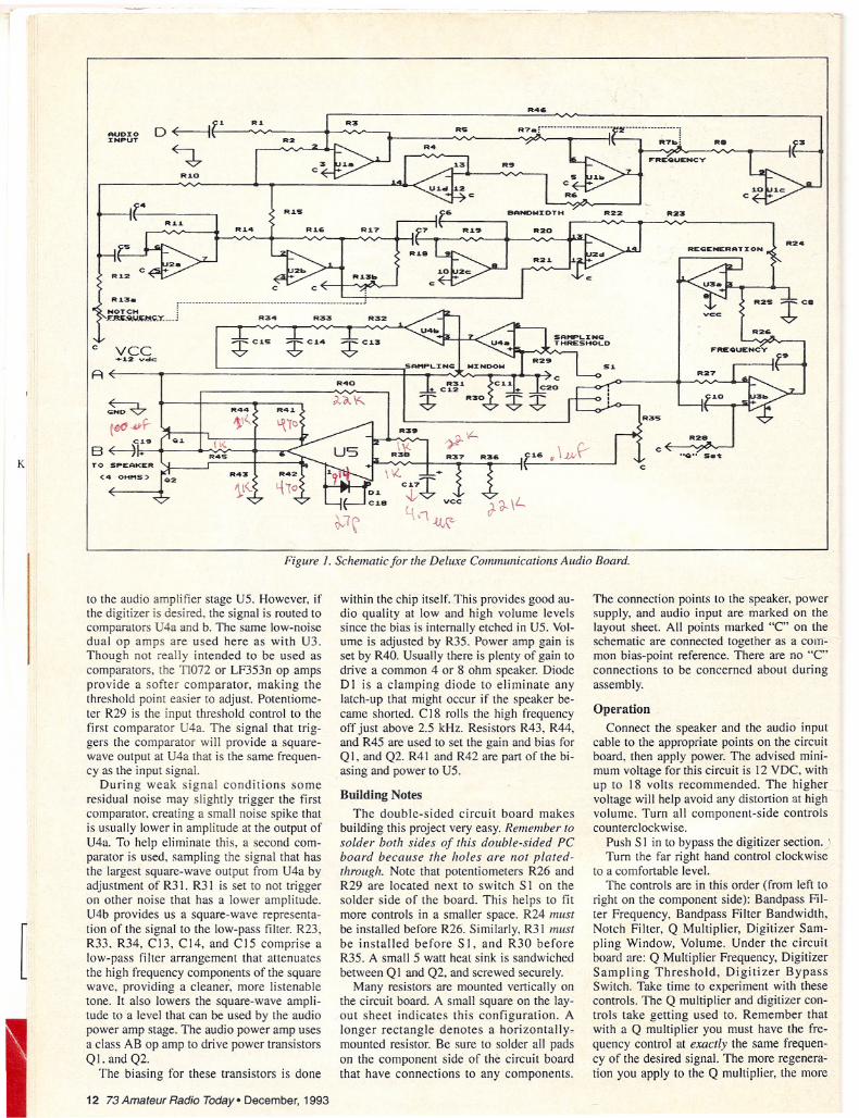
Circuit DescriptionThe schematic shows a lot of ICs and
parts, but don't let that fool you! The circuitis rather simple and can be followed easily atthe top left corner, labeled "Audio Input."CI is simply a DC blocking capacitor, whileR I sets the overall gain of the first section. Ifa very low audio signal is connected, R I canbe decreased in value to increase the gain.U Ia, b, c, and d are all low-noise quad opamps, which keeps the size down. The filterfrequency is adjusted with dual-gang potentiometer R7. The bandwidth is adjusted withR6, which controls the amount of feedback
to Ul a. The entire top portion of theschematic is the variable audio filter section.
The next stage is the notch filter locateddirectly below UI. U2a and c sections pro
vided a 180-degreephase shift of the frequency controlled byR 13a and b. Using twosections of notch filter
ing provides a verydeep null with steepskirts. Summing amplifiers U2b and d provide the. nodal pointwhere the phase-shifted frequency meets theoriginal signal and issubtracted to almostzero. U2 is also a lownoise quad op amp.Output of the notch
section is applied to R24, which is the regeneration control for the regenerative preamp.The regenerative preamp is located by itselfon the right side of the schematic. U3a and bmake up a dual low-noise op amp and, asyou can see, feedback is applied in desiredamounts from the output of U3a to U3b andout to the U3a input again. CIO, R27, C9,and R25 and 26 provide the adjustable frequency response for the filter. The potentiometer marked "Q" is adjusted once to allow smooth control of regeneration withR24. If oscillation develops, rotate R28 tothe point were oscillation just ceases. Thefrequency control has a fairly wide frequency range to facilitate most CW signals. Theaudio signal is sampled at the output of U3a,and directed to switch S I. Normally, S 1 isout or OFF, which applies the signal directly
R24
R8
.OQO. Set
R23
R28
R26
REGENERATXON
c
FREQUENCY
R3S
c
R32R33
R41.
R42
'-\10
R34
R1.4
1.
R44
1.\"(l<.
R4S R431..~<"
VCC+~2 vdc:
R40
R~3.
R1.1.
4
R1.0
R1.S
AUD:IO:INPUT
p· __ ••••• 4 ••• __ ._ •••••••• __ •• • •• _ ••• __ • oj
NOTCH :fJ!._r;_~IJ_r;.~.<;_..,. ;
c
TO SPEAKER
(4 OHt1S)
A
~
~~.qr-C.19 Q.1
B~+K
Figure J. Schematic for the Deluxe Communications Audio Board.
[
to the audio amplifier stage US. However, ifthe digitizer is desired, the signal is routed tocomparators U4a and b. The same low-noisedual op amps are used here as with U3.Though not really intended to be used ascomparators, the TIOn or LF353n op ampsprovide a softer comparator, making thethreshold point easier to adjust. Potentiometer R29 is the input threshold control to thefirst comparator U4a. The signal that triggers the comparator will provide a squarewave output at U4a that is the same frequency as the input signal.
During weak signal conditions someresidual noise may slightly trigger the firstcomparator. creating a small noise spike thatis usually lower in amplitude at the output ofU4a. To help eliminate this, a second comparator is used. sampling the signal that hasthe largest square-wave output from U4a byadjustment of R31. R31 is set to not triggeron other noise that has a lower amplitude.U4b provides us a square-wave representation of the signal to the low-pass filter. R23,R33, R34, C13, C14, and CIS comprise alow-pass filter arrangement that attenuatesthe high frequency components of the squarewave, providing a cleaner, more listenabletone. It also lowers the square-wave amplitude to a level that can be used by the audiopower amp stage. The audio power amp usesa class AB op amp to drive power transistorsQI. and Q2.
The biasing for these transistors is done
12 73 Amateur Radio Today· December, 1993
within the chip itself. This provides good audio quality at low and high volume levelssince the bias is internally etched in US. Volume is adjusted by R35. Power amp gain isset by R40. Usually there is plenty of gain todrive a common 4 or 8 ohm speaker. DiodeDI is a clamping diode to eliminate anylatch-up that might occur if the speaker became shorted. C 18 rolls the high frequencyoff just above 2.5 kHz. Resistors R43, R44,and R45 are used to set the gain and bias forQ I, and Q2. R4 I and R42 are part of the biasing and power to US.
Building NotesThe double-sided circuit board makes
building this project very easy. Remember tosolder both sides of this double-sided PCboard because the holes are not platedthrough. Note that potentiometers R26 andR29 are located next to switch S I on thesolder side of the board. This helps to fitmore controls in a smaller space. R24 mustbe installed before R26. Similarly, R31 mustbe installed before S I, and R30 beforeR35. A small 5 watt heat sink is sandwiched
between Q I and Q2, and screwed securely.Many resistors are mounted vertically on
the circuit board. A small square on the layout sheet indicates this configuration. Alonger rectangle denotes a horizontally.mounted resistor. Be sure to solder all padson the component side of the circuit boardthat have connections to any components.
The connection points to the speaker, powersupply, and audio input are marked on thelayout sheet. All points marked "e" on theschematic are connected together as a common bias-point reference. There are no "C"connections to be concerned about duringassembly.
Operation
Connect the speaker and the audio inputcable to the appropriate points on the circuitboard, then apply power. The advised minimum voltage for this circuit is 12 VDC, withup to 18 volts recommended. The highervoltage will help avoid any distortion at highvolume. Turn all component-side controlscounterclockwise.
Push S I in to bypass the digitizer section.)Turn the far right hand control clockwise
to a comfortable level.The controls are in this order (from left to
right on the component side): Bandpass Filter Frequency, Bandpass Filter Bandwidth,Notch Filter, Q Multiplier, Digitizer Sampling Window, Volume. Under the circuitboard are: Q Multiplier Frequency, DigitizerSampling Threshold, Digitizer BypassSwitch. Take time to experiment with thesecontrols. The Q multiplier and digitizer controls take getting used to. Remember thatwith a Q multiplier you must have the frequency control at exactly the same frequency of the desired signal. The more regenera:'tion you apply to the Q multiplier, the more

( I
Kl
(a.)
(b.)
(C.)
Figure 2. Double-sided PC board layout: a. Solder side; b. Component side; c. Parts placement diagram.
[
this requirement must be met. Another consequence of using large amounts of regeneration with the Q multiplier is that the CWsignal becomes elongated, like a bubble.You can hear this effect distinctly. The digitizer can minimize this effect by triggeringon the top portion of the elongated waveform. and then using the window comparator control to shore up the pulse width. Simply put, both controls can adjust the duty cycle when heavy regeneration from the Q
14 73 Amateur Radio Today· December, 1993
multiplier is needed. During regular operation, I recommend notching any undesiredsignal first, then apply the bandpass filter.Sometimes the Q multiplier works very wellto improve SSB or voice communication,but over-driving with too much output volume from the receiver will degrade it's ability to peak the desired signal.
Conclusion
This audio output section will provide
improved reception. It is perfect for an easyweekend project, or for someone who wantsto "go all the way" and build a complete receiver from scratch. This design matchesperfectly to an NE602 mixer or product detector. I would like to thank the authors for
engineering these fine circuits, and RandySeden for his computer design of the notchfilter section. iii
See Parts List on page 16.