numeric basics - ebook.pldworld.comebook.pldworld.com/_ebook/fpga/hdl/-examples-/numeric...
TRANSCRIPT
87
n u m e r i c bas i c s
One of the most common kinds of information processed by digital systems is numeric information. In this chapter, we will examine various binary codes for unsigned integers, signed integers, fixed-point fractions and floating-point real numbers. For each kind of code, we will describe how some arithmetic operations can be performed. We will also look at combinational circuits that implement arithmetic operations, and discuss trade-offs among different circuits that perform the same operation.
3.1 U N S I G N E D I N T E G E R S
In many applications of digital electronics, we deal with signals that only take on nonnegative integer values. Some signals may be representations of real-world information, for example, the temperature set on a thermo-stat. Other signals may arise as a consequence of the way we organize the digital system, for example, as numeric indices for tables of information stored in the system’s memory. In this section, we start with the most common representation for nonnegative integers, then describe arithmetic operations using that representation. We will finish the section by looking at an alternative representation that is used in some systems.
3.1.1 C O D I N G U N S I G N E D I N T E G E R S
We are all familiar with decimal positional representation of numbers. A decimal number such as 12410 denotes the sum of 1 hundred, 2 tens and 4 units. We use the subscript notation to specify that the number is to be interpreted as decimal, that is, base 10. The position of each digit in the number determines the power of 10 by which the digit is multiplied, starting with 100 for the right-most digit, 101 for the next digit to the left, and increasing by successive powers of ten for further digits from right to left. Thus, we write
3A-PDF Split DEMO : Purchase from www.A-PDF.com to remove the watermark
88 C H A P T E R T H R E E n u m e r i c b a s i c s
12410 � 1 � 102 � 2 � 101 � 4 � 100
In most applications that deal with nonnegative integers, the naturalway to represent the numeric values is using unsigned binary numbers.Unsigned binary representation works in the same way as decimal repre-sentation, except that we only use the binary digits 0 and 1 and we mul-tiply digits by powers of 2 instead of powers of 10. We can represent the same numeric value as 12410 in binary by determining the powers of two that sum to the number, namely,
12410� 1 � 26� 1 � 25� 1 � 24� 1 � 23� 1 � 22� 0 � 21� 0 � 20
� 11111002
So, to represent this number in a digital system, we would need seven single-bit signals, each carrying one bit of the binary number. In general, we represent a number x using n bits xn � 1, xn � 2, . . . , x0, with
x�xn � 12n � 1 �xn � 22n � 2 � . . .�x020
example 3 .1 What number is represented by the unsigned binary number 1011012?
solut ion Express the number as a sum of powers of two and calculate the result:
1011012 � 1 � 25 � 0 � 24 � 1 � 23 � 1 � 22 � 0 � 21 � 1 � 20
� 1 � 32 � 0 � 16 � 1 � 8 � 1 � 4 � 0 � 2 � 1 � 1
� 4510
Our discussion of binary codes in Section 2.2 applies equally to unsigned binary representation of numbers, since that is just one particu-lar binary code. Thus, given an n-bit unsigned binary code, we can repre-sent 2n distinct numbers. The smallest number has all 0 bits, representing the number 0, and the largest number has all 1 bits, representing
1� 2n � 1 � 1 � 2n � 2 � . . .� 1 � 21 � 1 � 20 � 2n � 1
Conversely, if we need to represent numbers between 0 and N� 1, we need at least ⎡log2N⎤ bits for the unsigned binary representation. In computer systems, unsigned binary numbers are typically 8, 16 or 32 bits long, allowing representation of numbers up to 256, over 65,000, and over 4 billion, respectively. However, when we are designing a digital sys-tem with no other constraints applied to the number of bits, we would typically choose the smallest number of bits that can represent the range of numbers we expect to encode. There is no reason why this should not be a number of bits other than 8, 16 or 32, such as 5, 17 or 26.
example 3 .2 Suppose we are designing a scientifi c instrument to measure the time interval between two random events very precisely, with a resolution of nanoseconds (1ns � 10�9 seconds). Events may occur as much as a day apart. How many bits are needed to represent the interval as a number of nanoseconds?
solut ion There are 109 nanoseconds per second, and 60�60�24�86,400 seconds per day, so the largest number we need to allow for is 8.64�1013. The number of bits needed is
⎡log2(8.64� 1013)⎤� ⎡log(8.64� 1013)���
log 2 ⎤ � ⎡46.296 . . .⎤� 47
So at least 47 bits are needed.
Unsigned Integers in Verilog
We saw in Section 2.1.3 that we can use vectors to model binary coded data. Since unsigned binary is just one form of binary code, we can use vectors for numeric data also, specifying ranges of index values for nets, variables and ports, and using indexing to refer to individual bits. When we look at arithmetic operations on unsigned integers, we will see how they can be modeled in Verilog as operations on vectors.
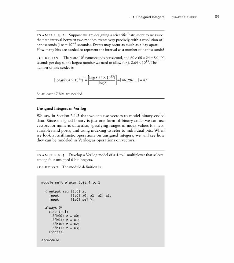
example 3 .3 Develop a Verilog model of a 4-to-1 multiplexer that selects among four unsigned 6-bit integers.
solut ion The module definition is
module multiplexer_6bit_4_to_1
( output reg [5:0] z,input [5:0] a0, a1, a2, a3,input [1:0] sel );
always @*case (sel)2'b00: z = a0;2'b01: z = a1;2'b10: z = a2;2'b11: z = a3;
endcase
endmodule
3.1 Unsigned Integers C H A P T E R T H R E E 89
90 C H A P T E R T H R E E n u m e r i c b a s i c s
This is much the same as the multiplexer model that we saw in Section 2.3.2. The input ports a0 through a3 and the output port z are all 6-bit unsigned vec-tors, indexed from 5 down to 0. We choose this index range so that the index of each bit in a vector corresponds to the power of its binary weight. The input port sel, used to select among the inputs, is also a vector, though we are not interpreting it as representing a number.
Octal and Hexadecimal Codes
We have seen that we need at least approximately log2N bits to represent the number N in unsigned binary form. The same number is represented in decimal with approximately log10N digits. Now
log2N� log 10N/ log 102� log 10N/0.301 . . . � log 10N� 3.32 . . .
In other words, we need more than three times as many binary digits as decimal digits to represent a given number. While that is not necessarilya problem in terms of the digital system, it is cumbersome and error prone for us to write down and read the long strings of bits required for large numbers. For this reason, we often use hexadecimal (base 16) or, less commonly, octal (base 8) for those purposes. We will show how these representations work first, then discuss the advantages of using them.
Octal is just another form of positional number system, except that we use the digits 0 through 7 and multiply them by powers of 8 depending on their position. Thus, for example,
2538 � 2 � 82 � 5 � 81 � 3 � 80
� 2 � 64 � 5 � 8 � 3 � 1
� 128 � 40 � 3 � 17110
More important, for a given octal number, we can factor out powers of two in each digit and so very quickly determine the binary representa-tion of the same number. For example,
2538 � 2 � 82 � 5 � 81 � 3 � 80
� (0 � 22 � 1 � 21 � 0 � 20)� 82 � (1 � 22 � 0 � 21 � 1 � 20)� 81
� (0 � 22 � 1 � 21 � 1 � 20)� 80
� (0 � 22 � 1 � 21 � 0 � 20)� 26 � (1 � 22 � 0 � 21 � 1 � 20)� 23
� (0 � 22 � 1 � 21 � 1 � 20)� 20
� (0 � 28 � 1 � 27 � 0 � 26)� (1 � 25 � 0 � 24 � 1 � 23)� (0 � 22 � 1 � 21 � 1 � 20)
� 0101010112
In general, given an octal number, we can replace each digit with the corresponding three binary digits to give the unsigned binary represen-
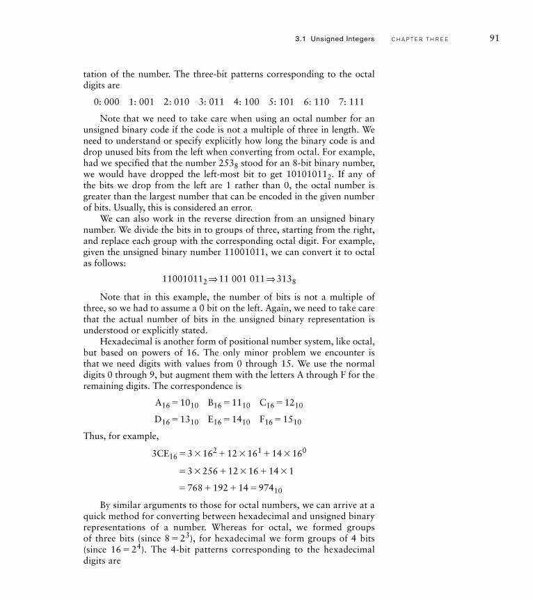
tation of the number. The three-bit patterns corresponding to the octal digits are
0: 000 1: 001 2: 010 3: 011 4: 100 5: 101 6: 110 7: 111
Note that we need to take care when using an octal number for an unsigned binary code if the code is not a multiple of three in length. We need to understand or specify explicitly how long the binary code is and drop unused bits from the left when converting from octal. For example, had we specified that the number 2538 stood for an 8-bit binary number, we would have dropped the left-most bit to get 101010112. If any of the bits we drop from the left are 1 rather than 0, the octal number is greater than the largest number that can be encoded in the given number of bits. Usually, this is considered an error.
We can also work in the reverse direction from an unsigned binary number. We divide the bits in to groups of three, starting from the right, and replace each group with the corresponding octal digit. For example, given the unsigned binary number 11001011, we can convert it to octal as follows:
110010112 ⇒ 11 001 011 ⇒ 3138
Note that in this example, the number of bits is not a multiple of three, so we had to assume a 0 bit on the left. Again, we need to take care that the actual number of bits in the unsigned binary representation is understood or explicitly stated.
Hexadecimal is another form of positional number system, like octal, but based on powers of 16. The only minor problem we encounter is that we need digits with values from 0 through 15. We use the normal digits 0 through 9, but augment them with the letters A through F for the remaining digits. The correspondence is
A16 � 1010 B16 � 1110 C16 � 1210
D16 � 1310 E16 � 1410 F16 � 1510
Thus, for example,
3CE16 � 3 � 162 � 12 � 161 � 14 � 160
� 3 � 256 � 12 � 16 � 14 � 1
� 768 � 192 � 14 � 97410
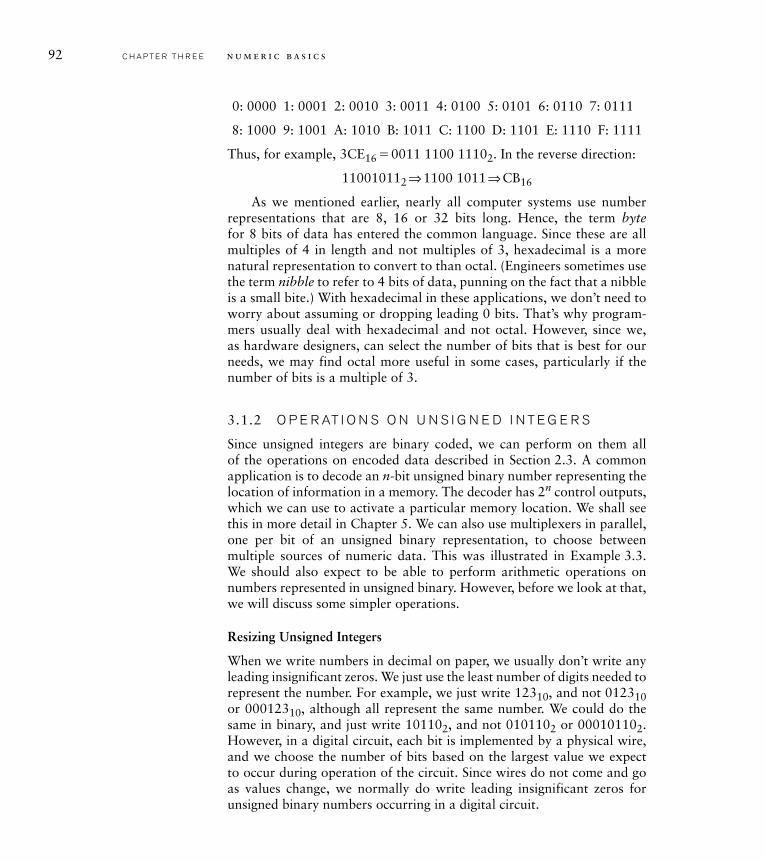
By similar arguments to those for octal numbers, we can arrive at a quick method for converting between hexadecimal and unsigned binary representations of a number. Whereas for octal, we formed groups of three bits (since 8 � 23), for hexadecimal we form groups of 4 bits (since 16 � 24). The 4-bit patterns corresponding to the hexadecimal digits are
3.1 Unsigned Integers C H A P T E R T H R E E 91
92 C H A P T E R T H R E E n u m e r i c b a s i c s
0: 0000 1: 0001 2: 0010 3: 0011 4: 0100 5: 0101 6: 0110 7: 0111
8: 1000 9: 1001 A: 1010 B: 1011 C: 1100 D: 1101 E: 1110 F: 1111
Thus, for example, 3CE16 � 0011 1100 11102. In the reverse direction:
110010112 ⇒ 1100 1011 ⇒ CB16
As we mentioned earlier, nearly all computer systems use number representations that are 8, 16 or 32 bits long. Hence, the term bytefor 8 bits of data has entered the common language. Since these are all multiples of 4 in length and not multiples of 3, hexadecimal is a more natural representation to convert to than octal. (Engineers sometimes use the term nibble to refer to 4 bits of data, punning on the fact that a nibble is a small bite.) With hexadecimal in these applications, we don’t need to worry about assuming or dropping leading 0 bits. That’s why program-mers usually deal with hexadecimal and not octal. However, since we, as hardware designers, can select the number of bits that is best for our needs, we may find octal more useful in some cases, particularly if the number of bits is a multiple of 3.
3.1.2 O P E R AT I O N S O N U N S I G N E D I N T E G E R S
Since unsigned integers are binary coded, we can perform on them all of the operations on encoded data described in Section 2.3. A common application is to decode an n-bit unsigned binary number representing the location of information in a memory. The decoder has 2n control outputs, which we can use to activate a particular memory location. We shall see this in more detail in Chapter 5. We can also use multiplexers in parallel,one per bit of an unsigned binary representation, to choose between multiple sources of numeric data. This was illustrated in Example 3.3. We should also expect to be able to perform arithmetic operations on numbers represented in unsigned binary. However, before we look at that, we will discuss some simpler operations.
Resizing Unsigned Integers
When we write numbers in decimal on paper, we usually don’t write any leading insignificant zeros. We just use the least number of digits needed to represent the number. For example, we just write 12310, and not 012310or 00012310, although all represent the same number. We could do the same in binary, and just write 101102, and not 0101102 or 000101102.However, in a digital circuit, each bit is implemented by a physical wire, and we choose the number of bits based on the largest value we expect to occur during operation of the circuit. Since wires do not come and go as values change, we normally do write leading insignificant zeros for unsigned binary numbers occurring in a digital circuit.
Recall that the largest value that can be represented with n bits is 2n � 1. Suppose we have some numeric data x represented with n bits:
x � xn � 12n � 1 � xn � 22n � 2 � . . . � x020
However, in order to perform some arithmetic operations, which may result in larger values than 2n � 1, we need to represent the same value in m bits, where m � n:
y � ym � 12m � 1 � . . . � yn2n � yn � 12n � 1 � yn � 22n � 2 � . . . � y020
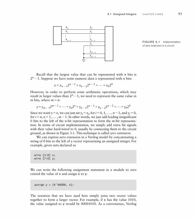
Since we want y � x, we can just set yi � xi, for i � 0, 1, . . . , n � 1, and yi � 0, for i � n, n � 1, . . . , m � 1. In other words, we just add leading insignificant 0 bits to the left of the n-bit representation to form the m-bit representa-tion. In terms of circuit implementation, we simply add extra bit signals with their value hard-wired to 0, usually by connecting them to the circuit ground, as shown in Figure 3.1. This technique is called zero extension.
We can express zero extension in a Verilog model by concatenating a string of 0 bits to the left of a vector representing an unsigned integer. For example, given nets declared as
wire [3:0] x;wire [7:0] y;
We can write the following assignment statement in a module to zero extend the value of x and assign it to y:
assign y = {4 ' b0000, x};
The notation that we have used here simply joins two vector values together to form a larger vector. For example, if x has the value 1010, the value assigned to y would be 00001010. As a convenience, Verilog
3.1 Unsigned Integers C H A P T E R T H R E E 93
F I G U R E 3 .1 Implementation of zero extension in a circuit.
x0
… ……
x1
xn − 1
y0
y1
yn − 1
yn
ym − 2
ym − 1
94 C H A P T E R T H R E E n u m e r i c b a s i c s
automatically zero extends a literal vector value to the specified size. So we could rewrite the above assignment as
assign y = {4 'b0, x};
In this case, Verilog extends the bit value 0 with additional 0 bits to make a total of 4 bits.
Verilog also allows us to perform zero extension implicitly. If we assign an unsigned vector of a smaller size to a vector net or variable of a larger size, the value is implicitly zero extended to the size of the assignment tar-get. For example, we could have written the above assignment simply as
assign y = x;
in which case the 4-bit value of x would be implicitly zero extended to 8 bits, the size of y. While this might appear to be a more succinct and convenient way to write the assignment, we should be aware that zero extension occurs. Using the vector concatenation operation makes the extension explicit, which better documents our design intent.
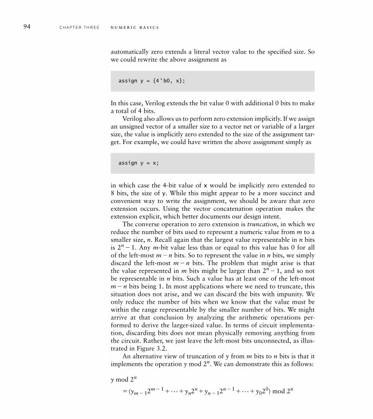
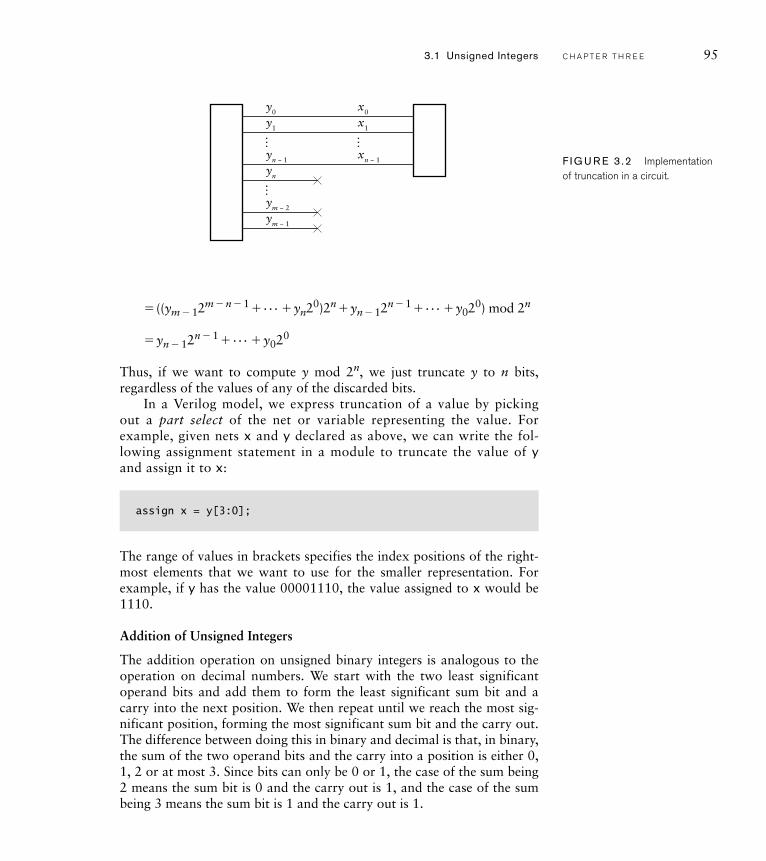
The converse operation to zero extension is truncation, in which we reduce the number of bits used to represent a numeric value from m to a smaller size, n. Recall again that the largest value representable in n bits is 2n � 1. Any m-bit value less than or equal to this value has 0 for all of the left-most m � n bits. So to represent the value in n bits, we simply discard the left-most m � n bits. The problem that might arise is that the value represented in m bits might be larger than 2n � 1, and so not be representable in n bits. Such a value has at least one of the left-most m � n bits being 1. In most applications where we need to truncate, this situation does not arise, and we can discard the bits with impunity. We only reduce the number of bits when we know that the value must be within the range representable by the smaller number of bits. We might arrive at that conclusion by analyzing the arithmetic operations per-formed to derive the larger-sized value. In terms of circuit implementa-tion, discarding bits does not mean physically removing anything from the circuit. Rather, we just leave the left-most bits unconnected, as illus-trated in Figure 3.2.
An alternative view of truncation of y from m bits to n bits is that it implements the operation y mod 2n. We can demonstrate this as follows:
y mod 2n
� (ym � 12m � 1 � . . .�yn2n �yn � 12n � 1 � . . . �y020) mod 2n
� ((ym � 12m � n � 1 � . . . � yn20)2n � yn � 12n � 1 � . . . � y020) mod 2n
� yn � 12n � 1 � . . . � y020
Thus, if we want to compute y mod 2n, we just truncate y to n bits, regardless of the values of any of the discarded bits.
In a Verilog model, we express truncation of a value by picking out a part select of the net or variable representing the value. For example, given nets x and y declared as above, we can write the fol-lowing assignment statement in a module to truncate the value of y and assign it to x:
assign x = y[3:0];
The range of values in brackets specifies the index positions of the right-most elements that we want to use for the smaller representation. For example, if y has the value 00001110, the value assigned to x would be 1110.
Addition of Unsigned Integers
The addition operation on unsigned binary integers is analogous to the operation on decimal numbers. We start with the two least significant operand bits and add them to form the least significant sum bit and a carry into the next position. We then repeat until we reach the most sig-nificant position, forming the most significant sum bit and the carry out. The difference between doing this in binary and decimal is that, in binary, the sum of the two operand bits and the carry into a position is either 0, 1, 2 or at most 3. Since bits can only be 0 or 1, the case of the sum being 2 means the sum bit is 0 and the carry out is 1, and the case of the sum being 3 means the sum bit is 1 and the carry out is 1.
…
y0
y1
yn − 1
x0
x1
xn − 1
yn
ym − 2
ym − 1
……
F I G U R E 3 .2 Implementation of truncation in a circuit.
3.1 Unsigned Integers C H A P T E R T H R E E 95
96 C H A P T E R T H R E E n u m e r i c b a s i c s
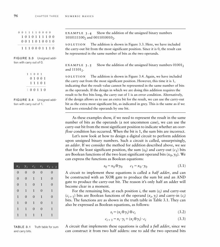
example 3 .4 Show the addition of the unsigned binary numbers 10101111002 and 00110100102.
solut ion The addition is shown in Figure 3.3. Here, we have included the carry-out bit from the most significant position. Since it is 0, the result can be represented in the same number of bits as the two operands.
example 3 .5 Show the addition of the unsigned binary numbers 010012 and 111012.
solut ion The addition is shown in Figure 3.4. Again, we have included the carry out from the most signifi cant position. However, this time it is 1, indicating that the result value cannot be represented in the same number of bits as the operands. If the design in which we are doing this addition requires the result to be fi ve bits long, the carry out of 1 is an error condition. Alternatively, if the design allows us to use an extra bit for the result, we can use the carry-out bit as the extra most signifi cant bit, as indicated in grey. This is the same as if we had zero extended the operands by one bit.
As these examples show, if we need to represent the result in the same number of bits as the operands (a not uncommon case), we can use the carry-out bit from the most significant position to indicate whether an over-flow condition has occurred. When the bit is 1, the sum bits are incorrect.
Let’s now look at how to design a digital circuit to perform addition upon unsigned binary numbers. Such a circuit is called, unsurprisingly, an adder. If we consider the method for addition described above, we see that for the least significant position, the sum (s0) and carry-out (c1) bits are Boolean functions of the two least significant operand bits (x0, y0). We can express the functions as Boolean equations:
s0 � x0 ⊕ y0 c1 � x0 � y0 (3.1)
A circuit to implement these equations is called a half adder, and can be constructed with an XOR gate to produce the sum bit and an AND gate to produce the carry-out bit. The reason it’s only half an adder will become clear in a moment.
For the remaining bits, at each position i, the sum (si) and carry-out (ci � 1) bits are Boolean functions of the operand (xi, yi) and carry-in (ci) bits. The functions are as shown in the truth table in Table 3.1. They can also be expressed as Boolean equations, as follows:
si � (xi ⊕ yi) ⊕ ci (3.2)
ci � 1 � xi � yi � (xi ⊕ yi) � ci (3.3)
A circuit that implements these equations is called a full adder, since we can construct it from two half adders: one to add the two operand bits
0 1 0 0 1
0 0 11 1 0
1 1 1 0 1
1 1 0 0 1
F I G U R E 3 .4 Unsigned addi-tion with carry out of 1.
1 0 1 0 1 1 1 1 0 0
1 1 1 0 0 0 1 1 1 0
0 0 1 1 0 1 0 0 1 0
0 0 1 1 1 1 0 0 0 0
F I G U R E 3 .3 Unsigned addi-tion with carry out of 0.
x i y i c i s i c i � 1
0 0 0 0 0
0 0 1 1 0
0 1 0 1 0
0 1 1 0 1
1 0 0 1 0
1 0 1 0 1
1 1 0 0 1
1 1 1 1 1
TAB LE 3 .1 Truth table for sum and carry bits.
and one to add the result of that with the carry-in bit. A small amount of additional logic is needed to form the carry out. However, this form of full adder is largely of historical interest, since constraints that apply in most designs lead to different implementations.
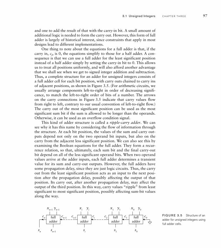
One thing to note about the equations for a full adder is that, if the carry in, ci, is 0, the equations simplify to those for a half adder. A con-sequence is that we can use a full adder for the least significant position instead of a half adder simply by setting the carry-in bit to 0. This allows us to treat all positions uniformly, and will also afford another advantage that we shall see when we get to signed integer addition and subtraction. Thus, a complete structure for an adder for unsigned integers consists of a full adder cell for each bit position, with carry outs chained to carry ins of adjacent positions, as shown in Figure 3.5. (For arithmetic circuits, we usually arrange components left-to-right in order of decreasing signifi-cance, to match the left-to-right order of bits of a number. The arrows on the carry connections in Figure 3.5 indicate that carry values flow from right to left, contrary to our usual convention of left-to-right flow.) The carry out of the most significant position can be used as the most significant sum bit if the sum is allowed to be longer than the operands. Otherwise, it can be used as an overflow condition signal.
This kind of adder structure is called a ripple-carry adder. We can see why it has this name by considering the flow of information through the structure. At each bit position, the values of the sum and carry out-puts depend not only on the two operand bit inputs, but also on the carry from the adjacent less significant position. We can also see this by examining the Boolean equations for the full adder. They form a recur-rence relation, so that, ultimately, each sum bit and the final carry-out bit depend on all of the less significant operand bits. When two operand values arrive at the adder inputs, each full adder determines a transient value for its sum and carry-out outputs. However, the full adders have some propagation delay, since they are just logic circuits. Thus, the carry out from the least significant position acts as an input to the next posi-tion after the propagation delay, possibly affecting the output of that position. Its carry out, after another propagation delay, may affect the output of the third position. In this way, carry values “ripple” from least significant to most significant position, possibly affecting sum-bit values along the way.
fulladder
xi
si
cici+1
yi
fulladder
x0
s0
c0c1
y0
fulladder
x1
s1
c2
y1
fulladder
xn–1
sn–1sn
cn–1cn
yn–1
F I G U R E 3 .5 Structure of an adder for unsigned integers using full adder cells.
3.1 Unsigned Integers C H A P T E R T H R E E 97
98 C H A P T E R T H R E E n u m e r i c b a s i c s
In the worst case, the delay from operand values arriving to the sum value settling is the product of each full adder’s propagation delay and the number of bits in the unsigned binary representation. If the performance constraints of the application allow for an addition to be done slowly, a ripple-carry adder is a simple and effective adder structure. However, many applications require that arithmetic operations have high perfor-mance in order to meet timing constraints. In those cases, we can find alternate adder structures that have less delay, though at the expense of greater circuit area and power consumption.
We will now outline a couple of ways in which we can improve the adder performance over that of a ripple-carry adder. As the basis of our discussion, let’s return to Equations 3.2 and 3.3 and to the truth table in Table 3.1. For a given position i, we can see the following properties.
If xi and yi are both 0, then ci � 1 � 0, regardless of the value of ci. In this case, any carry in to the position is killed. We define a signal for this condition:
ki �_xi �
_yi (3.4)
If one of xi and yi is 1 and the other is 0, then ci� 1 �ci. In this case, the carry in is propagated to the next position. A signal for this condition is
pi �xi ⊕yi (3.5)
If xi and yi are both 1, then ci � 1 � 1, regardless of the value of ci. In this case, a carry out is generated for the next position. We define a signal for this condition:
gi �xi �yi (3.6)
Substituting Equations 3.5 and 3.6 into Equations 3.2 and 3.3 gives
si �pi ⊕ci (3.7)
ci � 1 �gi �pi �ci (3.8)
One way in which these reformulated equations help is by exposing a way of determining the carry values at each position more quickly than the ripple-carry method. Note that the ki, pi and gi signals only depend on the operand bit values at their respective positions, so they can be determined quickly after the operand values arrive at the adder inputs. If a carry is killed or generated at a given position, we don’t need to wait for the carry in from less significant positions; we can drive a 0 or 1 carry-out value immediately. On the other hand, if carry is to be propagated, we
�
�
�
xi
gi pi ki
si
cici+1
yixi
pi
si
ci
ci+1
yi
0
1
+V
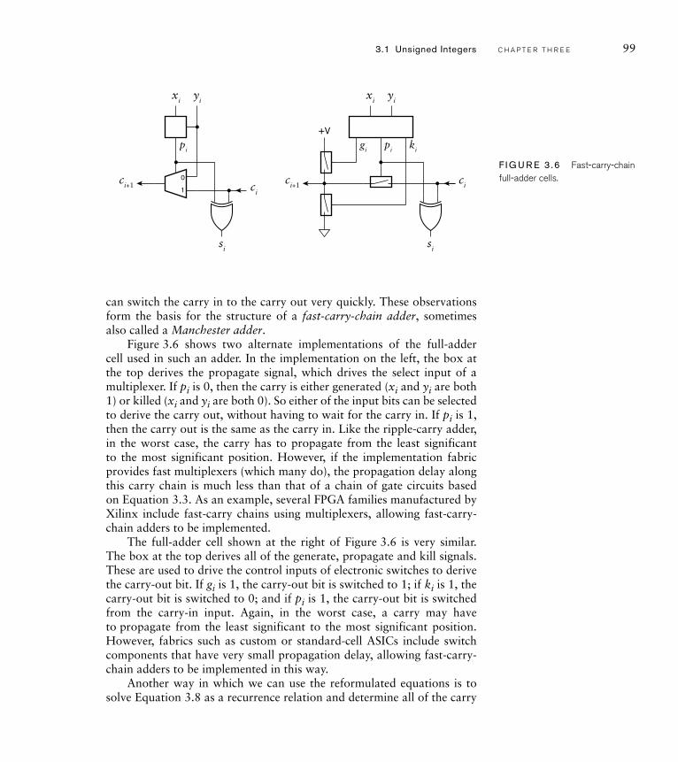
F I G U R E 3 .6 Fast-carry-chain full-adder cells.
3.1 Unsigned Integers C H A P T E R T H R E E 99
can switch the carry in to the carry out very quickly. These observations form the basis for the structure of a fast-carry-chain adder, sometimes also called a Manchester adder.
Figure 3.6 shows two alternate implementations of the full-adder cell used in such an adder. In the implementation on the left, the box at the top derives the propagate signal, which drives the select input of a multiplexer. If pi is 0, then the carry is either generated (xi and yi are both 1) or killed (xi and yi are both 0). So either of the input bits can be selected to derive the carry out, without having to wait for the carry in. If pi is 1, then the carry out is the same as the carry in. Like the ripple-carry adder, in the worst case, the carry has to propagate from the least significant to the most significant position. However, if the implementation fabric provides fast multiplexers (which many do), the propagation delay along this carry chain is much less than that of a chain of gate circuits based on Equation 3.3. As an example, several FPGA families manufactured by Xilinx include fast-carry chains using multiplexers, allowing fast-carry-chain adders to be implemented.
The full-adder cell shown at the right of Figure 3.6 is very similar. The box at the top derives all of the generate, propagate and kill signals. These are used to drive the control inputs of electronic switches to derive the carry-out bit. If gi is 1, the carry-out bit is switched to 1; if ki is 1, the carry-out bit is switched to 0; and if pi is 1, the carry-out bit is switched from the carry-in input. Again, in the worst case, a carry may have to propagate from the least significant to the most significant position. However, fabrics such as custom or standard-cell ASICs include switch components that have very small propagation delay, allowing fast-carry-chain adders to be implemented in this way.
Another way in which we can use the reformulated equations is to solve Equation 3.8 as a recurrence relation and determine all of the carry
100 C H A P T E R T H R E E n u m e r i c b a s i c s
x0
g0 p0
p3
s3
c0
c3
c4
y0x1
g1 p1
y1x2
g2 p2
y2x3
g3 p3
y3
p2
s2
c2 p1
s1
c1 p0
s0
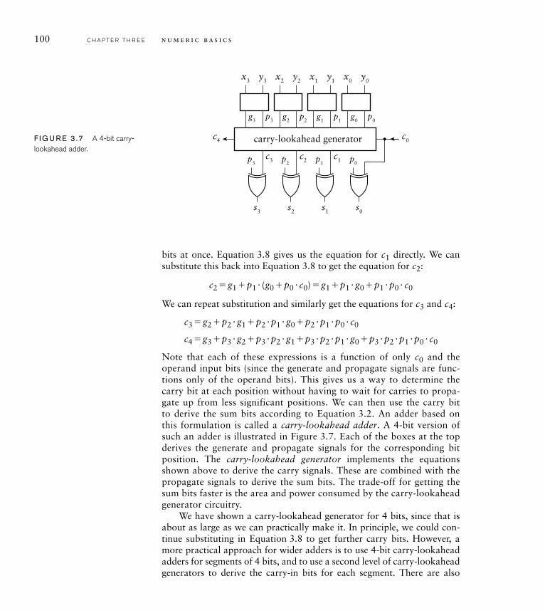
carry-lookahead generatorF I G U R E 3 .7 A 4-bit carry-lookahead adder.
bits at once. Equation 3.8 gives us the equation for c1 directly. We can substitute this back into Equation 3.8 to get the equation for c2:
c2 � g1 � p1 � (g0 � p0 � c0) � g1 � p1 � g0 � p1 � p0 � c0
We can repeat substitution and similarly get the equations for c3 and c4:
c3 � g2 � p2 � g1 � p2 � p1 � g0 � p2 � p1 � p0 � c0
c4 � g3 � p3 � g2 � p3 � p2 � g1 � p3 � p2 � p1 � g0 � p3 � p2 � p1 � p0 � c0
Note that each of these expressions is a function of only c0 and the operand input bits (since the generate and propagate signals are func-tions only of the operand bits). This gives us a way to determine the carry bit at each position without having to wait for carries to propa-gate up from less significant positions. We can then use the carry bit to derive the sum bits according to Equation 3.2. An adder based on this formulation is called a carry-lookahead adder. A 4-bit version of such an adder is illustrated in Figure 3.7. Each of the boxes at the top derives the generate and propagate signals for the corresponding bit position. The carry-lookahead generator implements the equations shown above to derive the carry signals. These are combined with the propagate signals to derive the sum bits. The trade-off for getting the sum bits faster is the area and power consumed by the carry-lookahead generator circuitry.
We have shown a carry-lookahead generator for 4 bits, since that is about as large as we can practically make it. In principle, we could con-tinue substituting in Equation 3.8 to get further carry bits. However, a more practical approach for wider adders is to use 4-bit carry-lookahead adders for segments of 4 bits, and to use a second level of carry-lookahead generators to derive the carry-in bits for each segment. There are also
other forms of adders that build upon the reformulated expressions to compute carry bits in different ways. The choice among them is a ques-tion of making trade-offs among circuit area, power and performance, constrained by the resources available in implementation fabrics. A full discussion of these adder structures is beyond the scope of this book, but there are many references that go into detail.
In all of our discussion of adders so far, we have not yet described how to model them in Verilog. We could simply translate the Bool-ean expressions in the various forms we have discussed into Verilog. However, doing so would disguise our design intent of adding unsigned binary numbers. In particular, a CAD tool would just try to implement the model as combinational circuitry, and may not readily be able to recognize the opportunity to use any specialized circuit resources, such as fast-carry chains, available in an implementation fabric. A much better approach is to use the addition operator provided by Verilog to operate on vector values. A synthesis CAD tool can then implement the addition operation using the most appropriate form of adder provided by the target fabric to meet design constraints. Alternatively, we could develop a structural model, selecting the most appropriate form of adder from a library of arithmetic components, and verify that the structural model produces the same results as a behavioral model using the addi-tion operator.
example 3 .6 Given the Verilog declaration of three nets:
wire [7:0] a, b, s;
write a Verilog statement to assign the sum of a and b to s.
solut ion The required statement is
assign s = a + b;
The � operator works on two unsigned values to produce an unsigned result whose length is the larger of the two operands. It does not produce a carry out, so if there is an overflow, it remains undetected.
example 3 .7 Revise the statements to produce a carry-out bit, c.
solut ion We can do this by zero extending a and b by one extra bit before doing the additions, in order to get a 9-bit result. The carry out is then
3.1 Unsigned Integers C H A P T E R T H R E E 101
102 C H A P T E R T H R E E n u m e r i c b a s i c s
the most significant bit of that result, and the 8-bit sum is the remaining bits. We need to declare a net for the 9-bit intermediate result and for the carry bit:
wire [8:0] tmp_result;wire c;
The required statements are
assign tmp_result = {1 'b0, a} + {1 'b0, b};assign c = tmp_result[8];assign s = tmp_result[7:0];
An alternative way of writing these assignments is
assign {c, s} = {1 'b0, a} + {1 'b0, b};
In this assignment, the left-hand side is written as a concatenation of the carry bit and sum nets. The bits of the result of addition are assigned to the corre-sponding bits of the concatenated nets. We can simplify this further, since Verilog has rules that cover implicit extension of expression operands based on the size of the left-hand side of an assignment. If we write
assign {c, s} = a + b;
the Verilog rules determine that the size of the left-hand side is 9 bits, so the values of a and b must be extended to 9 bits. Since they are unsigned values, they are implicitly zero extended, and the result of the addition is also 9 bits long. As we mentioned earlier, while these rules might appear to make the assignment more succinct, we must take care that implicit extensions have the effect we really want. If in doubt, or if we want to make our intent explicit, we can use explicit extension.
The above example shows how we can use vectors when we need to access the individual bits of the binary code. Often, we can raise the level of abstraction in our Verilog model by considering only the numeric aspects of data and not their binary encoding. Verilog allows us to do so using the type integer for numbers. We can declare a variable (but not a net) to be of type integer as follows:
integer n;
Integer variables are typically 32 bits long, though a Verilog implementa-tion is allowed to use a larger size. The range of values represented by a 32-bit integer includes the unsigned values up to approximately 2 billion. It also includes negative numbers, which we will discuss further in the next section.
example 3 .8 Revise the declaration and statement in Example 3.6 to use integer variables instead of vector nets.
solut ion The revised declaration is
integer a, b, s;
Since we are using variables instead of nets, the assignment must be in a proce-dural block. We replace the assignment statement with the always block:
always @*s = a + b;
The addition expression looks exactly like that in the original assignment. The only difference is that we are not concerned about the size of the variables and are ignoring the possibility of any carry out. A synthesis tool would infer at least a 32-bit adder with no overflow checking, since we have not indicated the actual range of values that can occur. That is one reason why we would not generally use integer types for synthesizable models where the range of values is known to be smaller than 32.
Subtraction of Unsigned Integers
We can work out how to perform subtraction of unsigned binary inte-gers by following a process similar to that for addition. First, we devise the steps for binary subtraction, bit by bit, analogously to subtraction of decimal digits. Recall that, in decimal, if we subtract a larger digit from a smaller digit, we borrow from the next column. We do the same in binary, borrowing if we subtract 1 from 0.
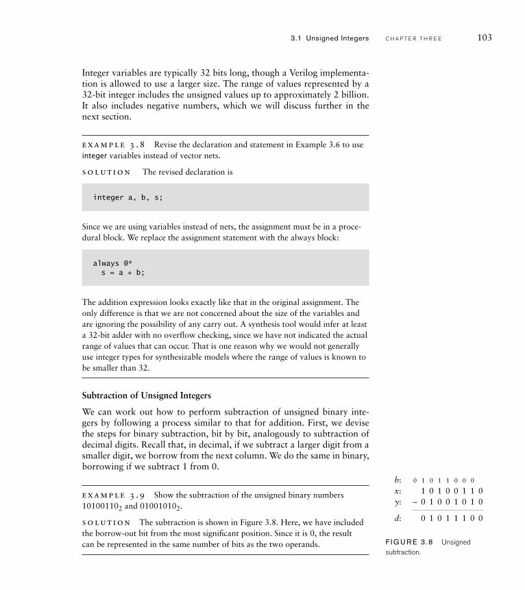
example 3 .9 Show the subtraction of the unsigned binary numbers 101001102 and 010010102.
solut ion The subtraction is shown in Figure 3.8. Here, we have included the borrow-out bit from the most signifi cant position. Since it is 0, the result can be represented in the same number of bits as the two operands.
1 0 1 0 0 1 1 0
0 1 0 1 1 1 0 0
0– 1 0 0 1 0 1 0
0 1 0 1 1 0 0 0
x:y:
d:
b:
F I G U R E 3 .8 Unsigned subtraction.
3.1 Unsigned Integers C H A P T E R T H R E E 103
104 C H A P T E R T H R E E n u m e r i c b a s i c s
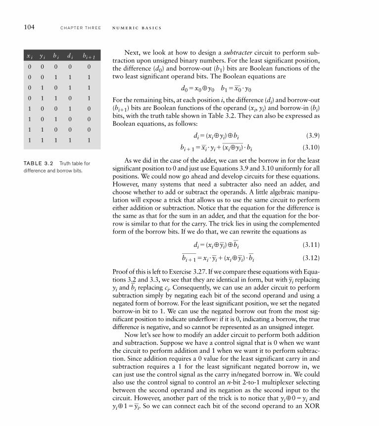
Next, we look at how to design a subtracter circuit to perform sub-traction upon unsigned binary numbers. For the least significant position, the difference (d0) and borrow-out (b1) bits are Boolean functions of the two least significant operand bits. The Boolean equations are
d0 �x0 ⊕y0 b1 �_x0 �y0
For the remaining bits, at each position i, the difference (di) and borrow-out (bi�1) bits are Boolean functions of the operand (xi, yi) and borrow-in (bi)bits, with the truth table shown in Table 3.2. They can also be expressed as Boolean equations, as follows:
di � (xi ⊕yi)⊕bi (3.9)
bi � 1 �_xi �yi �
____(xi⊕ yi) �bi (3.10)
As we did in the case of the adder, we can set the borrow in for the least significant position to 0 and just use Equations 3.9 and 3.10 uniformly for all positions. We could now go ahead and develop circuits for these equations. However, many systems that need a subtracter also need an adder, and choose whether to add or subtract the operands. A little algebraic manipu-lation will expose a trick that allows us to use the same circuit to perform either addition or subtraction. Notice that the equation for the difference is the same as that for the sum in an adder, and that the equation for the bor-row is similar to that for the carry. The trick lies in using the complemented form of the borrow bits. If we do that, we can rewrite the equations as
di � (xi ⊕_yi)⊕
_bi (3.11)
___bi � 1 �xi �
_yi � (xi ⊕
_yi) �
_bi (3.12)
Proof of this is left to Exercise 3.27. If we compare these equations with Equa-tions 3.2 and 3.3, we see that they are identical in form, but with
_yi replacing
yi and _bi replacing ci. Consequently, we can use an adder circuit to perform
subtraction simply by negating each bit of the second operand and using a negated form of borrow. For the least significant position, we set the negated borrow-in bit to 1. We can use the negated borrow out from the most sig-nificant position to indicate underflow: if it is 0, indicating a borrow, the true difference is negative, and so cannot be represented as an unsigned integer.
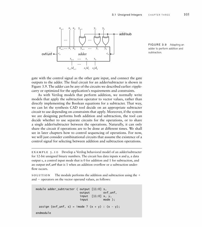
Now let’s see how to modify an adder circuit to perform both addition and subtraction. Suppose we have a control signal that is 0 when we want the circuit to perform addition and 1 when we want it to perform subtrac-tion. Since addition requires a 0 value for the least significant carry in and subtraction requires a 1 for the least significant negated borrow in, we can just use the control signal as the carry in/negated borrow in. We could also use the control signal to control an n-bit 2-to-1 multiplexer selecting between the second operand and its negation as the second input to the circuit. However, another part of the trick is to notice that yi⊕ 0 �yi and yi⊕ 1 �
_yi. So we can connect each bit of the second operand to an XOR
x i y i b i d i bi� 1
0 0 0 0 0
0 0 1 1 1
0 1 0 1 1
0 1 1 0 1
1 0 0 1 0
1 0 1 0 0
1 1 0 0 0
1 1 1 1 1
TAB LE 3 .2 Truth table for difference and borrow bits.
3.1 Unsigned Integers C H A P T E R T H R E E 105
y0y1yn–1
y0
c0cn
y1yn–1
…
…
…
…
x0x1xn–1
x0x1xn–1
… s0s1sn–1
sn–1/dn–1 s1/d1 s0/d0
…
adder
add/sub
ovf/unf
F I G U R E 3 .9 Adapting an adder to perform addition and subtraction.
gate with the control signal as the other gate input, and connect the gate outputs to the adder. The final circuit for an adder/subtracter is shown in Figure 3.9. The adder can be any of the circuits we described earlier: ripple-carry or optimized for the application’s requirements and constraints.
As with Verilog models that perform addition, we normally write models that apply the subtraction operator to vector values, rather than directly implementing the Boolean equations for a subtracter. That way, we can let the synthesis CAD tool decide on an appropriate subtracter circuit to use depending on constraints that apply. Moreover, if the system we are designing performs both addition and subtraction, the tool can decide whether to use separate circuits for the operations, or to share a single adder/subtracter between the operations. Naturally, it can only share the circuit if operations are to be done at different times. We shall see in later chapters how to control sequencing of operations. For now, we will just consider combinational circuits that assume the existence of a control signal for selecting between addition and subtraction operations.
example 3 .10 Develop a Verilog behavioral model of an adder/subtracter for 12-bit unsigned binary numbers. The circuit has data inputs x and y, a data output s, a control input mode that is 0 for addition and 1 for subtraction, and an output ovf_unf that is 1 when an addition overfl ow or a subtraction under-fl ow occurs.
solut ion The module performs the addition and subtraction using the � and � operators on the vector operand values, as follows:
module adder_subtracter ( output [11:0] s,output ovf_unf,input [11:0] x, y,input mode );
assign {ovf_unf, s} = !mode ? (x + y) : (x – y);
endmodule
106 C H A P T E R T H R E E n u m e r i c b a s i c s
The assignment in the module uses the mode input to choose between additionand subtraction of the operands. Since we want to use the carry-out or borrow-out bit for the ovf_unf output, we assign to the concatenation of the two outputs using the notation we saw in Example 3.7. Verilog implicitly extends the addi-tion and subtraction operands to match the 13-bit size of the assignment target. The least significant 12 bits of the result are used as the sum or difference output value and the most significant bit as the ovf_unf value. In the case of addition, the most significant bit is the carry out: 1 for overflow, or 0 otherwise. In the case of subtraction, the most significant bit is the borrow out, not negated: 1 for underflow, or 0 otherwise. Thus, we can use this bit for the ovf_unf output.
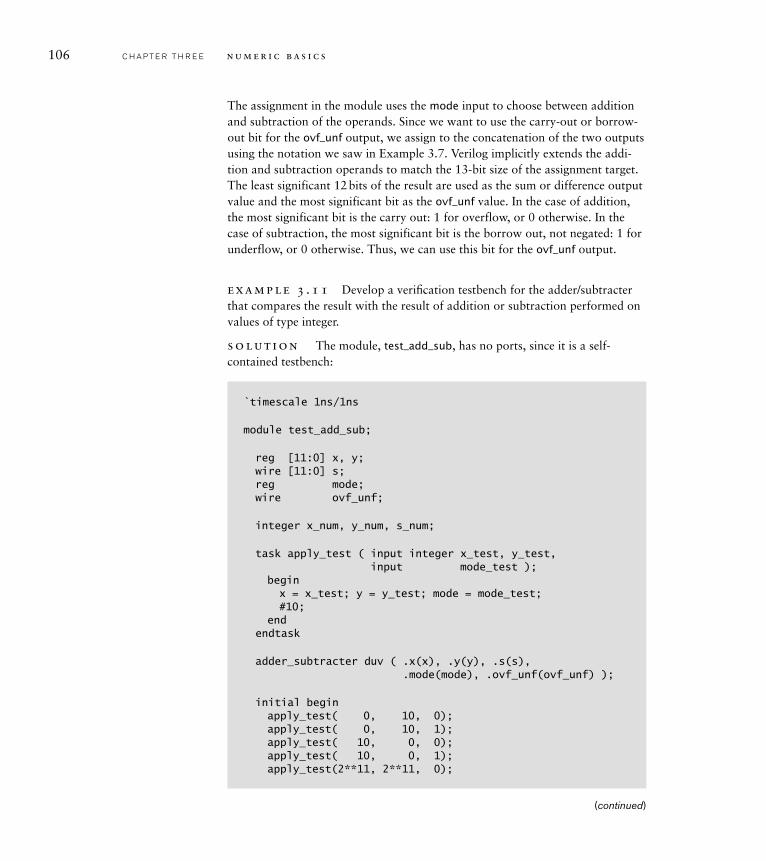
example 3 .11 Develop a verifi cation testbench for the adder/subtracter that compares the result with the result of addition or subtraction performed on values of type integer.
solut ion The module, test_add_sub, has no ports, since it is a self-contained testbench:
`timescale 1ns/1ns
module test_add_sub;
reg [11:0] x, y;wire [11:0] s;reg mode;wire ovf_unf;
integer x_num, y_num, s_num;
task apply_test ( input integer x_test, y_test,input mode_test );
beginx = x_test; y = y_test; mode = mode_test;#10;
endendtask
adder_subtracter duv ( .x(x), .y(y), .s(s),.mode(mode), .ovf_unf(ovf_unf) );
initial beginapply_test( 0, 10, 0);apply_test( 0, 10, 1);apply_test( 10, 0, 0);apply_test( 10, 0, 1);apply_test(2**11, 2**11, 0);
(continued)
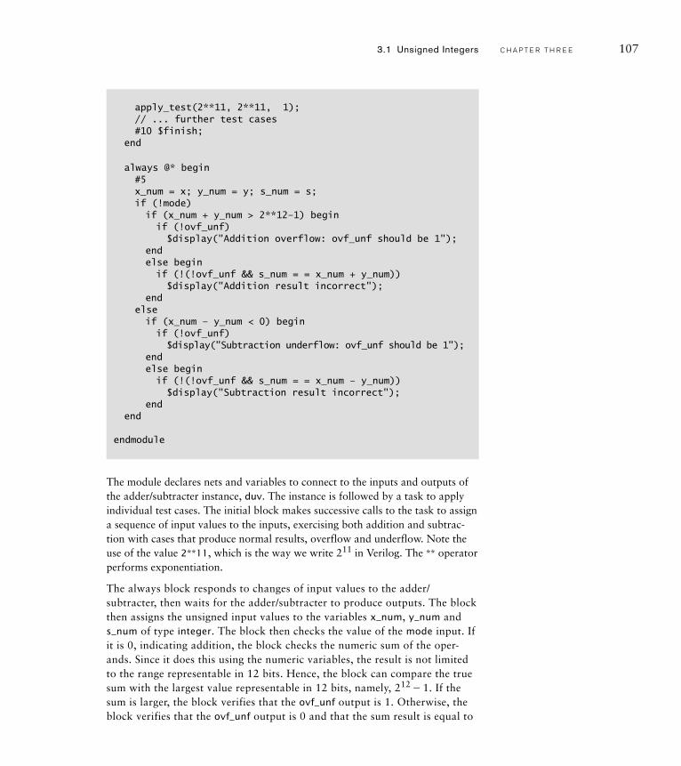
The module declares nets and variables to connect to the inputs and outputs of the adder/subtracter instance, duv. The instance is followed by a task to apply individual test cases. The initial block makes successive calls to the task to assign a sequence of input values to the inputs, exercising both addition and subtrac-tion with cases that produce normal results, overflow and underflow. Note the use of the value 2**11, which is the way we write 211 in Verilog. The ** operator performs exponentiation.
The always block responds to changes of input values to the adder/ subtracter, then waits for the adder/subtracter to produce outputs. The block then assigns the unsigned input values to the variables x_num, y_num and s_num of type integer. The block then checks the value of the mode input. If it is 0, indicating addition, the block checks the numeric sum of the oper-ands. Since it does this using the numeric variables, the result is not limited to the range representable in 12 bits. Hence, the block can compare the true sum with the largest value representable in 12 bits, namely, 212 � 1. If the sum is larger, the block verifies that the ovf_unf output is 1. Otherwise, the block verifies that the ovf_unf output is 0 and that the sum result is equal to
apply_test(2**11, 2**11, 1);// ... further test cases#10 $finish;
end
always @* begin#5x_num = x; y_num = y; s_num = s;if (!mode)if (x_num + y_num > 2**12–1) beginif (!ovf_unf)$display("Addition overflow: ovf_unf should be 1");
endelse beginif (!(!ovf_unf && s_num = = x_num + y_num))$display("Addition result incorrect");
endelseif (x_num – y_num < 0) beginif (!ovf_unf)$display("Subtraction underflow: ovf_unf should be 1");
endelse begin
if (!(!ovf_unf && s_num = = x_num – y_num)) $display("Subtraction result incorrect");
endend
endmodule
3.1 Unsigned Integers C H A P T E R T H R E E 107
108 C H A P T E R T H R E E n u m e r i c b a s i c s
the computed numeric sum. If mode is 1, indicating subtraction, the block performs similar checks, but compares the numeric difference between the operands with 0.
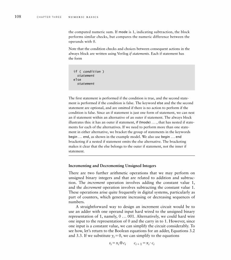
Note that the condition checks and choices between consequent actions in the always block are written using Verilog if statements. Each if statement has the form
if ( condition )statement
elsestatement
The first statement is performed if the condition is true, and the second state-ment is performed if the condition is false. The keyword else and the the second statement are optional, and are omitted if there is no action to perform if the condition is false. Since an if statement is just one form of statement, we can nest an if statement within an alternative of an outer if statement. The always block illustrates this: it has an outer if statement, if (!mode) . . . , that has nested if state-ments for each of the alternatives. If we need to perform more than one state-ment in either alternative, we bracket the group of statements in the keywords begin . . . end, as shown in the example model. We also use begin . . . end
bracketing if a nested if statement omits the else alternative. The bracketing makes it clear that the else belongs to the outer if statement, not the inner if statement.
Incrementing and Decrementing Unsigned Integers
There are two further arithmetic operations that we may perform on unsigned binary integers and that are related to addition and subtrac-tion. The increment operation involves adding the constant value 1, and the decrement operation involves subtracting the constant value 1. These operations arise quite frequently in digital systems, particularly as part of counters, which generate increasing or decreasing sequences of numbers.
A straightforward way to design an increment circuit would be to use an adder with one operand input hard wired to the unsigned binary representation of 1, namely, 0 . . . 001. Alternatively, we could hard wire one input to the representation of 0 and the carry in to 1. However, since one input is a constant value, we can simplify the circuit considerably. To see how, let’s return to the Boolean equations for an adder, Equations 3.2 and 3.3. If we substitute yi � 0, we can simplify to the equations
si �xi ⊕ci ci � 1 �xi �ci
halfadder
xi
si
ci
ci+1 halfadder
x0
s0
c1
halfadder
x1
s1
c2halfadder
xn–1
sn–1sn
cn–1
cn
+V
F I G U R E 3 .10 Structure of an incrementer for unsigned inte-gers using half adder cells.
3.1 Unsigned Integers C H A P T E R T H R E E 109
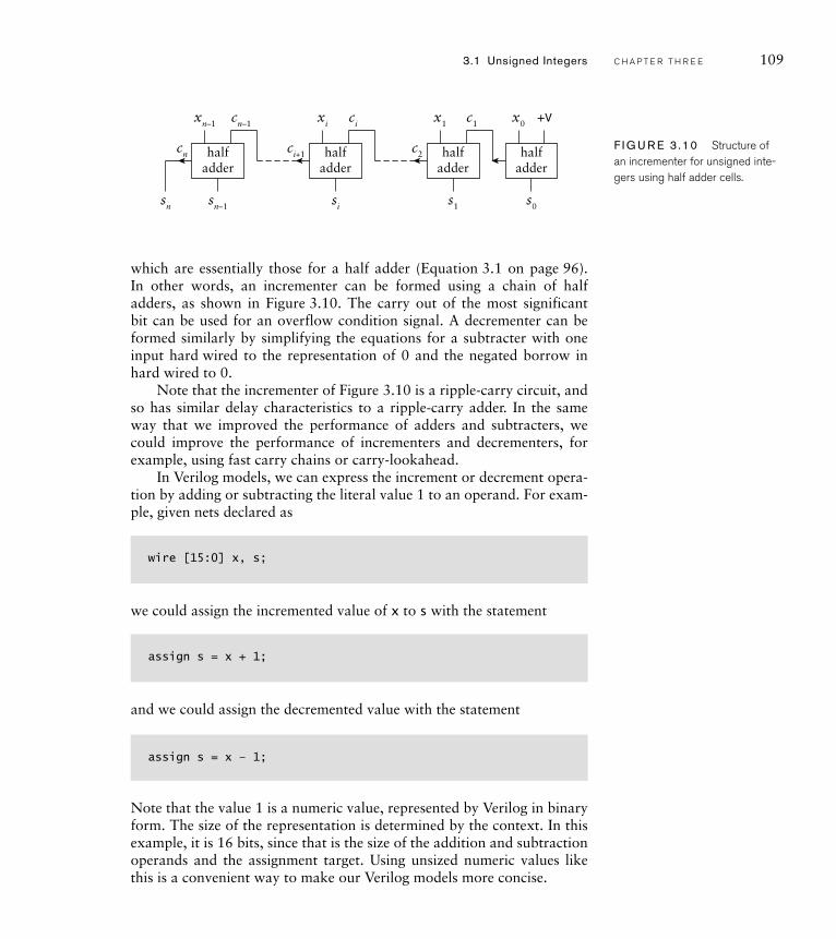
which are essentially those for a half adder (Equation 3.1 on page 96). In other words, an incrementer can be formed using a chain of half adders, as shown in Figure 3.10. The carry out of the most significant bit can be used for an overflow condition signal. A decrementer can be formed similarly by simplifying the equations for a subtracter with one input hard wired to the representation of 0 and the negated borrow in hard wired to 0.
Note that the incrementer of Figure 3.10 is a ripple-carry circuit, and so has similar delay characteristics to a ripple-carry adder. In the same way that we improved the performance of adders and subtracters, we could improve the performance of incrementers and decrementers, for example, using fast carry chains or carry-lookahead.
In Verilog models, we can express the increment or decrement opera-tion by adding or subtracting the literal value 1 to an operand. For exam-ple, given nets declared as
wire [15:0] x, s;
we could assign the incremented value of x to s with the statement
assign s = x + 1;
and we could assign the decremented value with the statement
assign s = x – 1;
Note that the value 1 is a numeric value, represented by Verilog in binary form. The size of the representation is determined by the context. In this example, it is 16 bits, since that is the size of the addition and subtraction operands and the assignment target. Using unsized numeric values like this is a convenient way to make our Verilog models more concise.
110 C H A P T E R T H R E E n u m e r i c b a s i c s
Comparison of Unsigned Integers
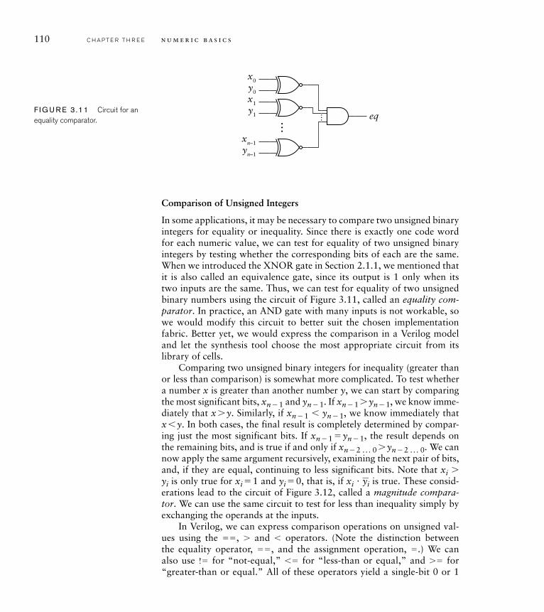
In some applications, it may be necessary to compare two unsigned binary integers for equality or inequality. Since there is exactly one code word for each numeric value, we can test for equality of two unsigned binary integers by testing whether the corresponding bits of each are the same. When we introduced the XNOR gate in Section 2.1.1, we mentioned that it is also called an equivalence gate, since its output is 1 only when its two inputs are the same. Thus, we can test for equality of two unsigned binary numbers using the circuit of Figure 3.11, called an equality com-parator. In practice, an AND gate with many inputs is not workable, so we would modify this circuit to better suit the chosen implementation fabric. Better yet, we would express the comparison in a Verilog model and let the synthesis tool choose the most appropriate circuit from its library of cells.
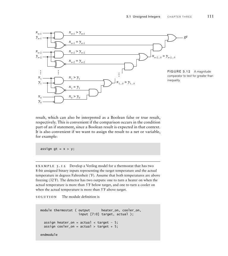
Comparing two unsigned binary integers for inequality (greater than or less than comparison) is somewhat more complicated. To test whether a number x is greater than another number y, we can start by comparing the most significant bits, xn � 1 and yn � 1. If xn � 1 � yn � 1, we know imme-diately that x � y. Similarly, if xn � 1 yn � 1, we know immediately that x y. In both cases, the final result is completely determined by compar-ing just the most significant bits. If xn � 1 � yn � 1, the result depends on the remaining bits, and is true if and only if xn � 2 . . . 0 � yn � 2 . . . 0. We can now apply the same argument recursively, examining the next pair of bits, and, if they are equal, continuing to less significant bits. Note that xi � yi is only true for xi � 1 and yi � 0, that is, if xi �
_ yi is true. These consid-
erations lead to the circuit of Figure 3.12, called a magnitude compara-tor. We can use the same circuit to test for less than inequality simply by exchanging the operands at the inputs.
In Verilog, we can express comparison operations on unsigned val-ues using the ��, � and operators. (Note the distinction between the equality operator, ��, and the assignment operation, �.) We can also use !� for “not-equal,” � for “less-than or equal,” and �� for “greater-than or equal.” All of these operators yield a single-bit 0 or 1
x0
eq…
y0
x1
y1
xn–1
yn–1
…F I G U R E 3 .11 Circuit for an equality comparator.
result, which can also be interpreted as a Boolean false or true result, respectively. This is convenient if the comparison occurs in the condition part of an if statement, since a Boolean result is expected in that context. It is also convenient if we want to assign the result to a net or variable, for example:
assign gt = x > y;
example 3 .12 Develop a Verilog model for a thermostat that has two 8-bit unsigned binary inputs representing the target temperature and the actual temperature in degrees Fahrenheit (˚F). Assume that both temperatures are above freezing (32˚F). The detector has two outputs: one to turn a heater on when the actual temperature is more than 5˚F below target, and one to turn a cooler on when the actual temperature is more than 5˚F above target.
solut ion The module definition is
module thermostat ( output heater_on, cooler_on,input [7:0] target, actual );
assign heater_on = actual < target – 5;assign cooler_on = actual > target + 5;
endmodule
xn–1
gtxn–1 > yn–1
xn–1 = yn–1
xn–2 > yn–2
xn–2 = yn–2
yn–1
xn–2
yn–2
x1 > y1
x1…0 > y1…0
xn–2…0 > yn–2…0
x1 = y1
x1
y1
x0 > y0x0
y0
…… … F I G U R E 3 .12 A magnitude comparator to test for greater than inequality.
3.1 Unsigned Integers C H A P T E R T H R E E 111
112 C H A P T E R T H R E E n u m e r i c b a s i c s
The assignments use the subtraction and addition operators to calculate the thresholds for turning the heater and cooler on. They use the and � operators for performing the comparisons against the thresholds.
Scaling by a Constant Power of 2
Before we turn to multiplying unsigned integers in a general way, let’s look at the specific case of scaling an unsigned integer by a given constant value that is a power of 2. The simplest case is multiplying by 2. Recall that the value x represented by the n bits xn� 1, xn� 2, . . . , x0 is
x�xn� 12n� 1 �xn� 22n� 2 � . . . � x020 (3.13)
If we multiply both sides by 2, we get
2x�xn� 12n �xn� 22n� 1 � . . . � x021 � (0)20
which is an n � 1 bit number consisting of the bits of x, shifted left by one position, and a 0 bit appended as the least significant bit. If we are working with fixed-length integers, we can truncate the most significant bit to yield an n-bit number, provided the truncated bit is 0. This opera-tion is called a logical shift left by one position. We can take this form of scaling further. To scale by a factor of 2k, we repeat the scaling-by-2 process k times. That is, we shift the bits left by k positions and append k bits of 0 to the least significant end. If we need to truncate to an n-bit result, the k truncated bits must all be zero; otherwise an overflow has occurred.
Dividing by 2 works similarly. If we divide both sides of Equation 3.13 by 2 we get
x/2�xn� 12n� 2 �xn� 22n� 3 � . . . � x120 �x02 � 1
Since 2 �1 is the fraction ½, and we are dealing with integers only, we can discard the last term in this equation. The result is an n� 1 bit number consisting of the bits of x, except for the least significant bit, shifted right by one position. If we are working with fixed-length integers, we can append a 0 to the most significant end to maintain the value. This opera-tion is called a logical shift right by one position.
We can take this further also. To divide by 2k, we shift the bits right by k positions, discarding the k least significant bits and appending k bits of 0 at the most significant end. If any of the discarded bits were nonzero, the true result of the division is truncated toward 0.
Verilog provides two operators for shifting the bits of an unsigned value. The operator performs a logical shift left, and the �� operator performs a logical shift right. For example, if the unsigned net or vari-able s has the value 00010011, representing the value 1910, the Verilog expression
s << 2
would yield the value 01001100, representing the value 7610. The expression
s >> 2
would yield the value 00000100, representing the value 410.
Multiplication of Unsigned Integers
The final arithmetic operation on unsigned integers that we shall examine is multiplication. A straightforward approach for multiplying x by y is to expand the product out as follows:
xy�x(yn� 12n� 1 �yn� 22n� 2 � . . . � y020)
�yn� 1x2n� 1 �yn� 2x2n� 2 � . . . � y0x20
The largest value of the product is the product of the largest values of the operands. For n-bit operands, that is
(2n � 1)(2n � 1) � 22n � 2n � 2n � 1 � 22n � (2n� 1 � 1)
which requires 2n bits to represent. If we provide this many bits for the product, there is no possibility of overflow.
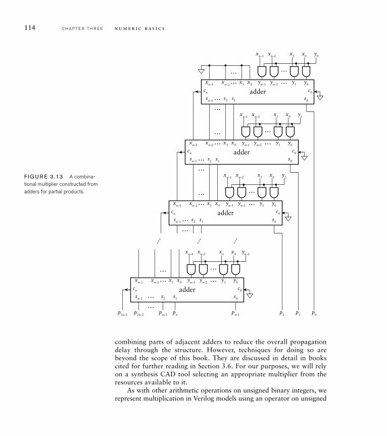
Each of the terms in the expanded product equation is called a partial product, and consists of the product of a bit yi, the number xand 2i. Recall that x2i is just the bits of x shifted left by i positions. Also, yi is either 0 or 1. If it is 0, the partial product is 0. If it is 1, the partial product is just the shifted version of x. Thus the partial product can be formed by AND-ing each bit of x with yi and adding it, shifted i places to the left, into the final product. The addition of the partial prod-ucts can be performed by a series of adders, as shown in Figure 3.13. This is a basic form of combinational multiplier, so called because it is a combinational circuit (albeit a large one). In Chapter 4, we will look at techniques that allow us to construct a sequential multiplier, in which we add partial products one at a time in successive clock cycles. A sequential multiplier trades off reduced area against time taken to yield the product.
In the multiplier circuit of Figure 3.13, we have not specified what kind of adder to use. We could use any of the adders we discussed earlier, with the choice depending on the performance requirements and area constraints that apply. We could also optimize the circuit by
3.1 Unsigned Integers C H A P T E R T H R E E 113
114 C H A P T E R T H R E E n u m e r i c b a s i c s
combining parts of adjacent adders to reduce the overall propagation delay through the structure. However, techniques for doing so are beyond the scope of this book. They are discussed in detail in books cited for further reading in Section 3.6. For our purposes, we will rely on a synthesis CAD tool selecting an appropriate multiplier from the resources available to it.
As with other arithmetic operations on unsigned binary integers, we represent multiplication in Verilog models using an operator on unsigned
x0 y1x1xn–1
y0
c0cn
y1yn–1 yn–2
…
……
xn–2
x0x1xn–2
… s0s1s2
xn–1
…
sn–1
… s1s2
…
… … …
sn–1
adder
x0 y2x1xn–1
y0
c0cn
y1yn–1 yn–2
…
…
…
…
xn–2
x0x1xn–2
s0
xn–1
…
adder
… s1s2
…
sn–1
x0 y0x1xn–1
y0
c0cn
y1yn–1 yn–2
…
…
…
…
xn–2
x0x1xn–2
s0
xn–1
adder
… s1s2
…
sn–1
x0 yn–1x1xn–1
y0
c0cn
y1yn–1 yn–2
…
…
…
…
xn–2
p0p1p2pn–1pnpn+1p2n–2p2n–1
x0x1xn–2
s0
xn–1
adder
F I G U R E 3 .13 A combina-tional multiplier constructed from adders for partial products.
values. The result of the * operator is an unsigned vector whose length is the larger of the operand lengths. If we need the multiplication to be performed with size that is the sum of the operand lengths, in order not to overflow, we must extend the operand values before multiplying them. For example, given the following declarations:
wire [ 7:0] x;wire [13:0] y;wire [21:0] p;
we could assign the product of x and y to p with the following statement:
assign p = {14'b0, x} * {8'b0, y};
Alternatively, we could rely on Verilog’s implicit zero extension and just write:
assign p = x * y;
Summary of Arithmetic Operations
In this section, we have examined several arithmetic operations that can be performed on unsigned binary integers, including addition, subtrac-tion and multiplication. We have deliberately avoided division, since it is considerably more complex to implement than the other operations, and arises less frequently in real-world applications. Hence, there are relatively few application-specific digital systems that include circuits for performing division. Division circuits are described in the books cited in Section 3.6.
In our discussion, we focused on addition as a foundational operation and examined a number of adder circuits that trade off between perfor-mance and circuit area. This is a recurring theme in digital design, and is well illustrated through consideration of adder circuits. We return to it throughout this book.
For each operation, we also discussed how to represent the opera-tion in Verilog models that use unsigned vectors. This approach allows us to abstract away from the details of the digital circuits that implement the arithmetic operations, relying on synthesis CAD tools to choose appropriate circuits from libraries of cells that can be implemented in
3.1 Unsigned Integers C H A P T E R T H R E E 115
116 C H A P T E R T H R E E n u m e r i c b a s i c s
the target fabric. As we shall see when we describe our implementation methodology in more detail, we separate the concerns of specifying the circuit behavior in Verilog and constraining the implementation. We provide speed and area constraints for use by the synthesis tool to determine an appropriate implementation. This approach helps us manage the complexity of designing systems to perform numerical computation.
3.1.3 G R AY C O D E S
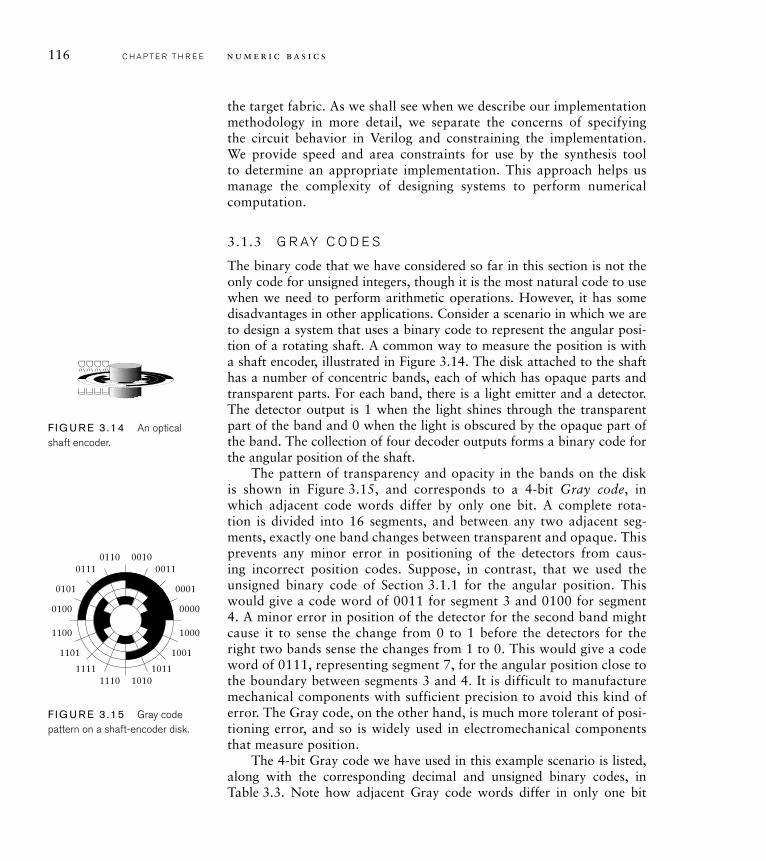
The binary code that we have considered so far in this section is not the only code for unsigned integers, though it is the most natural code to use when we need to perform arithmetic operations. However, it has some disadvantages in other applications. Consider a scenario in which we are to design a system that uses a binary code to represent the angular posi-tion of a rotating shaft. A common way to measure the position is with a shaft encoder, illustrated in Figure 3.14. The disk attached to the shaft has a number of concentric bands, each of which has opaque parts and transparent parts. For each band, there is a light emitter and a detector. The detector output is 1 when the light shines through the transparent part of the band and 0 when the light is obscured by the opaque part of the band. The collection of four decoder outputs forms a binary code for the angular position of the shaft.
The pattern of transparency and opacity in the bands on the disk is shown in Figure 3.15, and corresponds to a 4-bit Gray code, in which adjacent code words differ by only one bit. A complete rota-tion is divided into 16 segments, and between any two adjacent seg-ments, exactly one band changes between transparent and opaque. This prevents any minor error in positioning of the detectors from caus-ing incorrect position codes. Suppose, in contrast, that we used the unsigned binary code of Section 3.1.1 for the angular position. This would give a code word of 0011 for segment 3 and 0100 for segment 4. A minor error in position of the detector for the second band might cause it to sense the change from 0 to 1 before the detectors for the right two bands sense the changes from 1 to 0. This would give a code word of 0111, representing segment 7, for the angular position close to the boundary between segments 3 and 4. It is difficult to manufacture mechanical components with sufficient precision to avoid this kind of error. The Gray code, on the other hand, is much more tolerant of posi-tioning error, and so is widely used in electromechanical components that measure position.
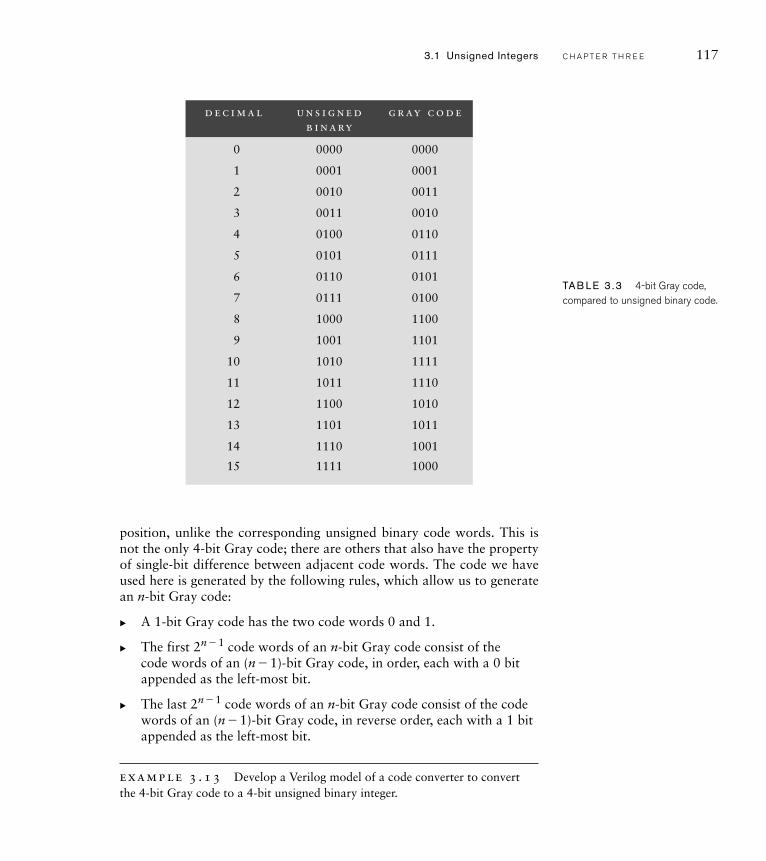
The 4-bit Gray code we have used in this example scenario is listed, along with the corresponding decimal and unsigned binary codes, in Table 3.3. Note how adjacent Gray code words differ in only one bit
F I G U R E 3 .14 An optical shaft encoder.
0000
00010101
1100 1000
10011101
1111 10111110 1010
0111 00110110 0010
0100
F I G U R E 3 .15 Gray code pattern on a shaft-encoder disk.
3.1 Unsigned Integers C H A P T E R T H R E E 117
position, unlike the corresponding unsigned binary code words. This is not the only 4-bit Gray code; there are others that also have the property of single-bit difference between adjacent code words. The code we have used here is generated by the following rules, which allow us to generate an n-bit Gray code:
A 1-bit Gray code has the two code words 0 and 1.
The first 2n� 1 code words of an n-bit Gray code consist of the code words of an (n� 1)-bit Gray code, in order, each with a 0 bit appended as the left-most bit.
The last 2n� 1 code words of an n-bit Gray code consist of the code words of an (n� 1)-bit Gray code, in reverse order, each with a 1 bit appended as the left-most bit.
example 3 .13 Develop a Verilog model of a code converter to convert the 4-bit Gray code to a 4-bit unsigned binary integer.
�
�
�
d e c i m a l u n s i g n e d b i n a ry
g r ay c o d e
0 0000 0000
1 0001 0001
2 0010 0011
3 0011 0010
4 0100 0110
5 0101 0111
6 0110 0101
7 0111 0100
8 1000 1100
9 1001 1101
10 1010 1111
11 1011 1110
12 1100 1010
13 1101 1011
14 1110 1001
15 1111 1000
TAB LE 3 .3 4-bit Gray code, compared to unsigned binary code.
118 C H A P T E R T H R E E n u m e r i c b a s i c s
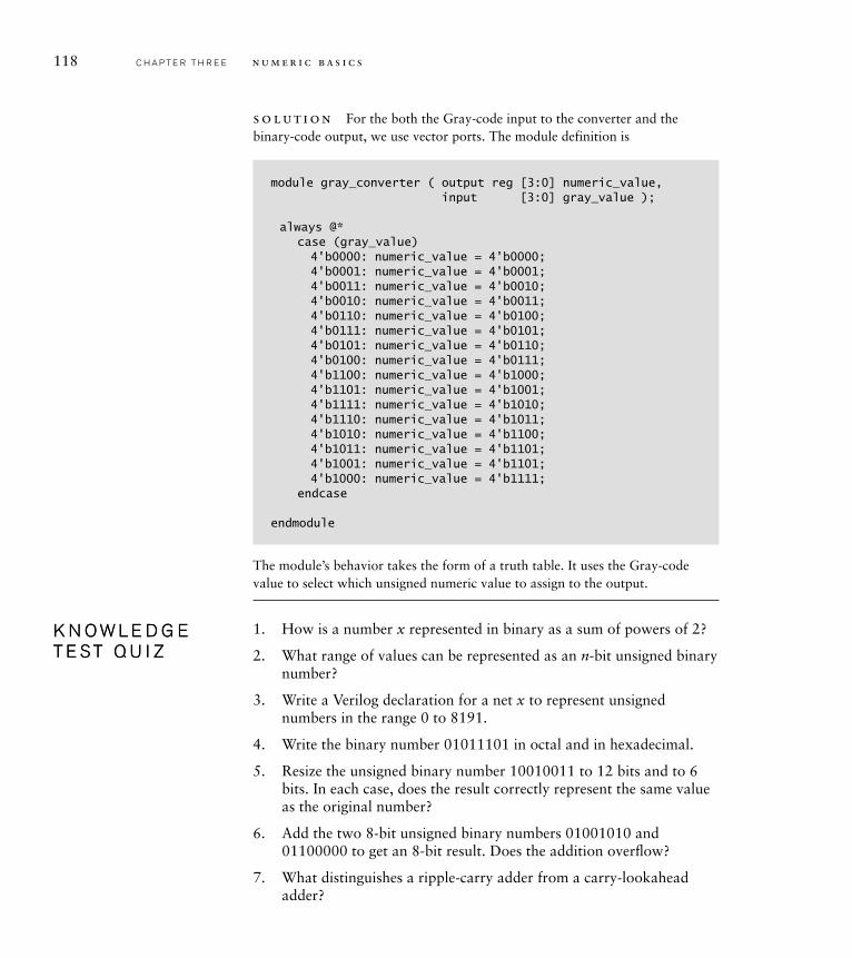
solut ion For the both the Gray-code input to the converter and the binary-code output, we use vector ports. The module definition is
module gray_converter ( output reg [3:0] numeric_value,input [3:0] gray_value );
always @*case (gray_value)4'b0000: numeric_value = 4'b0000;4'b0001: numeric_value = 4'b0001;4'b0011: numeric_value = 4'b0010;4'b0010: numeric_value = 4'b0011;4'b0110: numeric_value = 4'b0100;4'b0111: numeric_value = 4'b0101;4'b0101: numeric_value = 4'b0110;4'b0100: numeric_value = 4'b0111;4'b1100: numeric_value = 4'b1000;4'b1101: numeric_value = 4'b1001;4'b1111: numeric_value = 4'b1010;4'b1110: numeric_value = 4'b1011;4'b1010: numeric_value = 4'b1100;4'b1011: numeric_value = 4'b1101;4'b1001: numeric_value = 4'b1101;4'b1000: numeric_value = 4'b1111;
endcase
endmodule
The module’s behavior takes the form of a truth table. It uses the Gray-code value to select which unsigned numeric value to assign to the output.
1. How is a number x represented in binary as a sum of powers of 2?
2. What range of values can be represented as an n-bit unsigned binary number?
3. Write a Verilog declaration for a net x to represent unsigned numbers in the range 0 to 8191.
4. Write the binary number 01011101 in octal and in hexadecimal.
5. Resize the unsigned binary number 10010011 to 12 bits and to 6 bits. In each case, does the result correctly represent the same value as the original number?
6. Add the two 8-bit unsigned binary numbers 01001010 and 01100000 to get an 8-bit result. Does the addition overfl ow?
7. What distinguishes a ripple-carry adder from a carry-lookahead adder?
K N O W L E D G E T E S T Q U I ZK N O W L E D G E T E S T Q U I Z
8. Write Verilog assignments to add two nets s1 and s2 of type wire [15:0] to get a result net s3 of the same type as s1 and s2 and a carry-out net c_out.
9. Perform the 8-bit unsigned binary subtraction 01001010 � 01100000 to get an 8-bit result. Does the subtraction underfl ow?
10. Given a control signal __add/sub, how can we adapt an unsigned
adder to perform both addition and subtraction?
11. Write a Verilog assignment that compares two unsigned nets a and band assigns 1 to a net smaller if ab, or 0 otherwise.
12. How is an unsigned binary number multiplied by 16? How is it divided by 16?
13. How many bits are required for the product of two n-bit unsigned binary numbers?
14. Why are Gray codes often used in electromechanical position sensors?
3.2 S I G N E D I N T E G E R S
While many applications deal only with nonnegative integers, there are others that deal with integers that range over both positive and negative values. In this section we will explore a binary code for signed integers and see how to implement operations on these encoded values.
3.2.1 C O D I N G S I G N E D I N T E G E R S
The predominant encoding used in digital systems for signed integers is called 2s complement. It is a special case of radix complement representa-tion in which the radix (the base used for positional representation) is 2. We will refer to the Further Reference books for details of general radix comple-ment representations, and focus our attention here just on 2s complement.
A signed number is represented in 2s-complement form as a weighted sum of powers of two, in a similar way to unsigned binary representation. The difference is that, for an n-bit signed number, the weight of the left-most bit is negative. An n-bit number x represents the value
x��xn� 12n� 1 �xn� 22n� 2 � . . . �x020 (3.14)
This representation has a number of interesting and useful properties that we will now explore. First, the most negative number that can be represented has xn� 1 � 1 and all other bits 0, giving the value �2n� 1.The most positive number has xn� 1 � 0 and all other bits 1, giving the value 2n� 1 � 1. If xn� 1 is 1, the number represented is negative, since the sum of all the positively weighted powers of 2 is less than 2n� 1. Thus, xn� 1 serves as a sign bit: if it is 1, the number is negative, and if it is 0, the
3.2 Signed Integers C H A P T E R T H R E E 119
120 C H A P T E R T H R E E n u m e r i c b a s i c s
number is zero or positive. The range of numbers that can be represented is not symmetric about zero, since the negation of �2n� 1 is one more than the most positive number that can be represented.
example 3 .14 What values are represented by the 8-bit 2s-complement numbers 00110101 and 10110101?
solut ion The first number is
1� 25 � 1 � 24 � 1 � 22 � 1 � 20 � 32 � 16 � 4 � 1 � 53
The second number is
� 1 � 27 � 1 � 25 � 1 � 24 � 1 � 22 � 1 � 20 �� 128 � 32 � 16 � 4 � 1 ��75
While 2s-complement representation for signed integers predomi-nates, there are other forms that are useful in some applications. One form, signed magnitude, is analogous to our conventional decimal representa-tion for signed integers, in which we write a sequence of decimal digits for the magnitude of a number, preceded by a � or � sign to indicate whether the number is positive or negative. In signed magnitude binary representa-tion, we represent a signed number with a sequence of binary digits (bits), preceded by a binary code for the sign of the number. Usually, we would encode a � sign with 1 and a � sign with 0. While some early digital computers used signed magnitude representation, there are a number of disadvantages that make it uncommon in modern digital systems. For this reason, we will not describe in any further detail, and instead refer to the books listed in Section 3.6, Further Reading, for more information.
Representing Signed Integers in Verilog
We saw in Section 3.1.1 that we can use vectors and built-in arithme-tic operators to deal with unsigned integers. For signed integers, we also use vectors, but we include the keyword signed in their declarations, for example:
wire signed [ 7:0] a;reg signed [13:0] b;
The arithmetic operators then assume 2s-complement representation, with the sign bit being the left-most bit in a vector and the least significant bit being the right-most bit.
An important point to note is that, even though we might declare nets or variables to be unsigned or signed, the interpretation of the bits of a
value depends on the operator being applied and the declaration of the other operand. If both operands to an arithmetic operation are signed, a signed operation is performed. If either or both operations are unsigned, an unsigned operation is performed. If we really want to interpret values that are declared unsigned as representing signed values, we can use the $signed conversion operation, for example:
wire [11:0] s1;wire signed [11:0] s2;...assign s2 = $signed(s1); // s1 is known to be less than 2**11
Similarly, if we want to interpret values declared signed as represent-ing unsigned values, we use the $unsigned conversion operation, for example:
assign s1= $unsigned(s2); // s2 is known to be nonnegative
We also mentioned the abstract numeric type integer in Section 3.1.1, showing how it can be used for nonnegative numbers. In fact, the inte-ger type represents numbers that can be positive or negative, provided their 2s-complement representation can fit within 32 bits. We can perform arithmetic operations on values of type integer, and we can mix inte-ger with unsigned and signed net and variable values. The type integer is really just a signed variable type whose size is fixed at 32 bits.
Octal and Hexadecimal Codes for Signed Integers
We saw in Section 3.1.1 that we could use octal or hexadecimal codes for unsigned integers. We can also use octal and hexadecimal for 2s-complement signed integers. However, when we do so, we don’t usually think in terms of signed octal or signed hexadecimal numbers. Instead, we just use octal or hexadecimal as a shorthand notation for the vector of bits. We divide the vector into groups of three bits (for octal) or four bits (for hexadecimal) and substitute the corresponding octal or hexadecimal digit for each group.
example 3 .15 The 12-bit 2s-complement representation of 84410 is 001101001100. Express the bit vector in hexadecimal.
solut ion Dividing into groups of four bits, we get 0011 0100 1100. Substituting hexadecimal digits for the 4-bit groups gives 34C16.
3.2 Signed Integers C H A P T E R T H R E E 121
122 C H A P T E R T H R E E n u m e r i c b a s i c s
example 3 .16 The 10-bit 2s-complement representation of �42 is 1111010110. Express the bit vector in octal.
solut ion Dividing into groups of three bits, we get 1 111 010 110. Substituting octal digits for the 3-bit groups gives 17268. When reading this octal number, we need to understand that it represents 10 bits. The right-most three digits represent 9 bits, and the left-most digit represents just one bit, the sign bit. Since the sign bit is 1, the number is negative, even though the octal number does not include a � sign.
3.2.2 O P E R AT I O N S O N S I G N E D I N T E G E R S
As with unsigned numbers and binary codes in general, we can perform operations on signed integers that don’t rely on their numeric interpreta-tion, such as selecting among several encoded numbers using multiplex-ers. In this section, we will describe operations that relate to the numeric interpretation, such as arithmetic operations. Most of these operations are implemented in a similar way to their counterparts for unsigned integers.
Resizing Signed Integers
The resizing operation on unsigned integers simply involved appending or truncating leading zeros to reach the desired length of representation while maintaining the same numeric value. With 2s-complement num-bers, however, the left-most bit is the sign bit, so appending or truncating leading zeros will not work in general. Let’s consider the two cases of nonnegative and negative numbers, respectively.
For nonnegative numbers, the sign bit is 0, and the remaining bits constitute the magnitude of the number. In this case, the 2s-complement representation is the same as the unsigned representation, and zero extend-ing it maintains the same value. We can also truncate leading zeros, as we did for unsigned numbers, provided both that none of the truncated bits is 1 and that the left-most bit of the result is 0. Were the left-most bit of the result 1, that would imply a negative result, which would be incorrect. For example, the 8-bit 2s-complement representation of 4110 is 00101001. Truncating this to 6 bits would give 101001, which, interpreted as a 2s-complement number, is �23. The problem is that 4110 cannot be rep-resented in 6-bit 2s-complement.
For negative numbers, the sign bit is 1. We can extend an n-bit negativenumber to m bits by appending leading 1 bits. To see that this conserves the negative numeric value, consider the value represented by a negative number x:
x��2n� 1 �xn� 2 2n� 2 � . . . �x020 (3.15)
Extending this with leading 1 bits gives the 2s-complement number
�2m � 1 � 2m � 2 � . . . � 2n � 1 � xn � 2 2n � 2 � . . . � x020 (3.16)
We can make use of the following identity:
2k � 2k � 1 � 2k � 2 � . . . � 20 � 1 (3.17)
Expanding the first term in Equation 3.16 using this identity gives
� 2m � 2 � . . . � 2n � 1 �2n � 2 � . . . � 20 � 1
� 2m � 2 � . . . � 2n � 1 � xn � 2 2n � 2 � . . . � x020
� � 2n � 2 � . . . � 20 � 1 � xn � 2 2n � 2 � . . . � x020
� � (2n � 2 � . . . � 20 � 1) � xn � 2 2n � 2 � . . . � x020
� � 2n � 1 � xn � 2 2n � 2� . . . � x020 � x
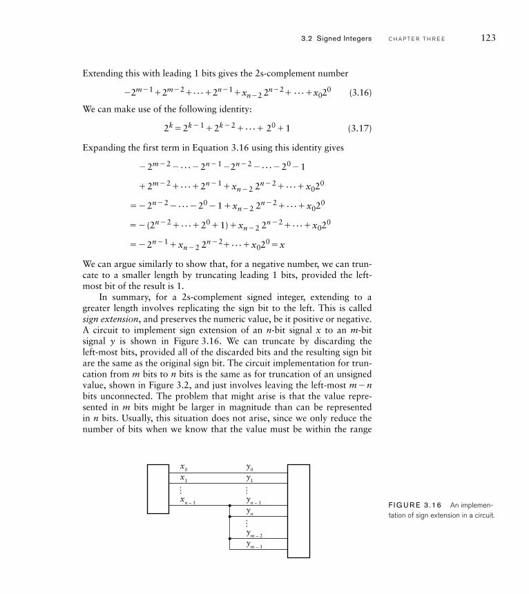
We can argue similarly to show that, for a negative number, we can trun-cate to a smaller length by truncating leading 1 bits, provided the left-most bit of the result is 1.
In summary, for a 2s-complement signed integer, extending to a greater length involves replicating the sign bit to the left. This is called sign extension, and preserves the numeric value, be it positive or negative. A circuit to implement sign extension of an n-bit signal x to an m-bit signal y is shown in Figure 3.16. We can truncate by discarding the left-most bits, provided all of the discarded bits and the resulting sign bit are the same as the original sign bit. The circuit implementation for trun-cation from m bits to n bits is the same as for truncation of an unsigned value, shown in Figure 3.2, and just involves leaving the left-most m � nbits unconnected. The problem that might arise is that the value repre-sented in m bits might be larger in magnitude than can be represented in n bits. Usually, this situation does not arise, since we only reduce the number of bits when we know that the value must be within the range
… ……
x0
x1
xn − 1
y0
y1
yn − 1
yn
ym − 2
ym − 1
F I G U R E 3 .16 An implemen-tation of sign extension in a circuit.
3.2 Signed Integers C H A P T E R T H R E E 123
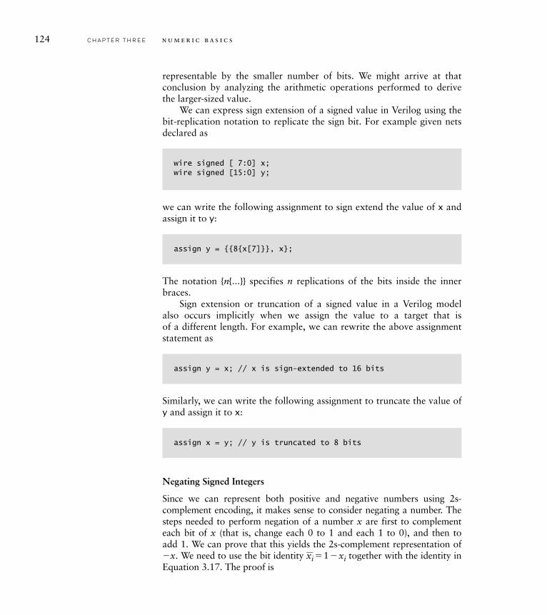
124 C H A P T E R T H R E E n u m e r i c b a s i c s
representable by the smaller number of bits. We might arrive at that conclusion by analyzing the arithmetic operations performed to derive the larger-sized value.
We can express sign extension of a signed value in Verilog using the bit-replication notation to replicate the sign bit. For example given nets declared as
wire signed [ 7:0] x;wire signed [15:0] y;
we can write the following assignment to sign extend the value of x and assign it to y:
assign y = {{8{x[7]}}, x};
The notation {n{...}} specifies n replications of the bits inside the inner braces.
Sign extension or truncation of a signed value in a Verilog model also occurs implicitly when we assign the value to a target that is of a different length. For example, we can rewrite the above assignment statement as
assign y = x; // x is sign-extended to 16 bits
Similarly, we can write the following assignment to truncate the value of y and assign it to x:
assign x = y; // y is truncated to 8 bits
Negating Signed Integers
Since we can represent both positive and negative numbers using 2s-complement encoding, it makes sense to consider negating a number. The steps needed to perform negation of a number x are first to complement each bit of x (that is, change each 0 to 1 and each 1 to 0), and then to add 1. We can prove that this yields the 2s-complement representation of �x. We need to use the bit identity
_xi� 1 �xi together with the identity in
Equation 3.17. The proof is
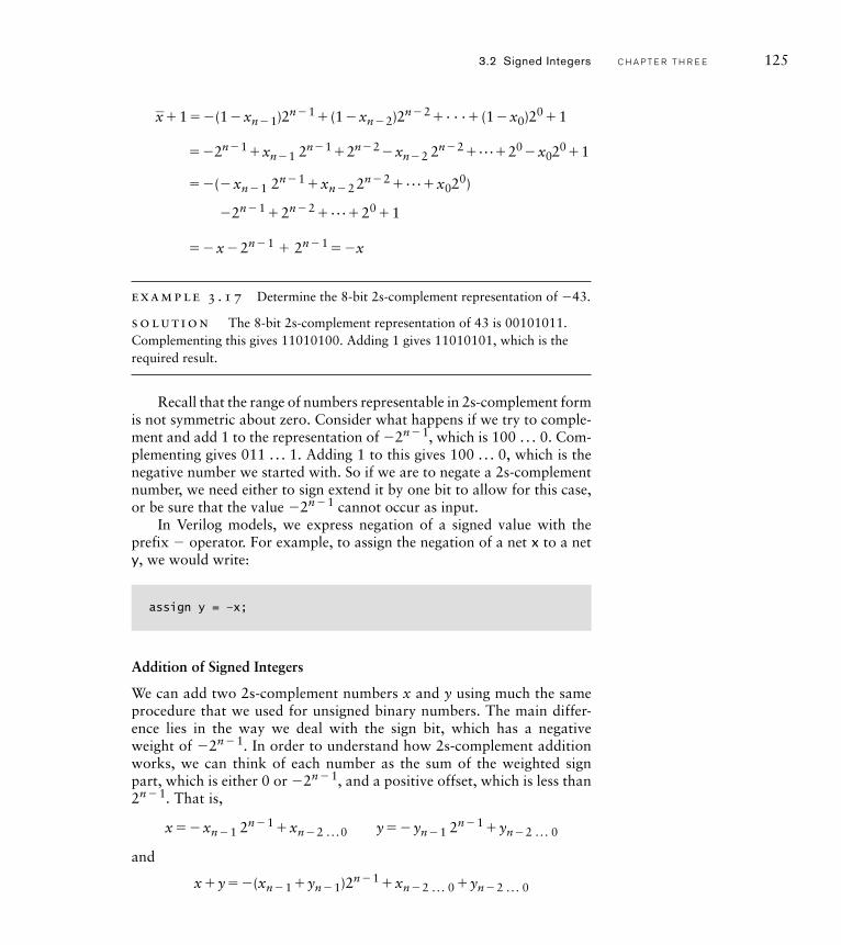
_x� 1 ��(1�xn� 1)2n� 1� (1 �xn� 2)2n� 2� . . .� (1 �x0)20� 1
��2n� 1�xn� 1 2n� 1� 2n� 2�xn� 2 2n� 2� . . .� 20�x020� 1
��(�xn� 1 2n� 1 �xn� 2 2n� 2 � . . .�x020)
�2n� 1 � 2n� 2 � . . .� 20 � 1
��x� 2n� 1 � 2n� 1 ��x
example 3 .17 Determine the 8-bit 2s-complement representation of �43.
solut ion The 8-bit 2s-complement representation of 43 is 00101011. Complementing this gives 11010100. Adding 1 gives 11010101, which is the required result.
Recall that the range of numbers representable in 2s-complement form is not symmetric about zero. Consider what happens if we try to comple-ment and add 1 to the representation of �2n� 1, which is 100 . . . 0. Com-plementing gives 011 . . . 1. Adding 1 to this gives 100 . . . 0, which is the negative number we started with. So if we are to negate a 2s-complement number, we need either to sign extend it by one bit to allow for this case, or be sure that the value �2n� 1 cannot occur as input.
In Verilog models, we express negation of a signed value with the prefix � operator. For example, to assign the negation of a net x to a net y, we would write:
assign y = –x;
Addition of Signed Integers
We can add two 2s-complement numbers x and y using much the same procedure that we used for unsigned binary numbers. The main differ-ence lies in the way we deal with the sign bit, which has a negative weight of �2n � 1. In order to understand how 2s-complement addition works, we can think of each number as the sum of the weighted sign part, which is either 0 or �2n � 1, and a positive offset, which is less than 2n � 1. That is,
x�� xn� 1 2n� 1 �xn� 2 . . . 0 y�� yn� 1 2
n� 1 �yn� 2 . . . 0
and
x�y��(xn� 1 �yn� 1)2n� 1 �xn� 2 . . . 0 �yn� 2 . . . 0
3.2 Signed Integers C H A P T E R T H R E E 125
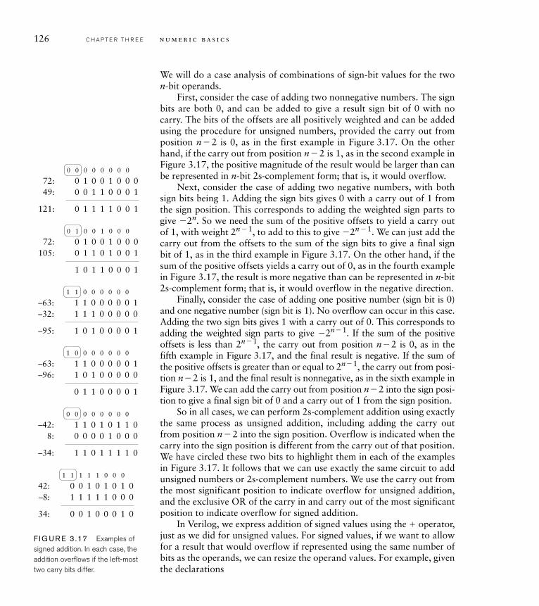
126 C H A P T E R T H R E E n u m e r i c b a s i c s
We will do a case analysis of combinations of sign-bit values for the two n-bit operands.
First, consider the case of adding two nonnegative numbers. The sign bits are both 0, and can be added to give a result sign bit of 0 with no carry. The bits of the offsets are all positively weighted and can be added using the procedure for unsigned numbers, provided the carry out from position n � 2 is 0, as in the first example in Figure 3.17. On the other hand, if the carry out from position n � 2 is 1, as in the second example in Figure 3.17, the positive magnitude of the result would be larger than can be represented in n-bit 2s-complement form; that is, it would overflow.
Next, consider the case of adding two negative numbers, with both sign bits being 1. Adding the sign bits gives 0 with a carry out of 1 from the sign position. This corresponds to adding the weighted sign parts to give �2n. So we need the sum of the positive offsets to yield a carry out of 1, with weight 2n � 1, to add to this to give �2n � 1. We can just add the carry out from the offsets to the sum of the sign bits to give a final sign bit of 1, as in the third example in Figure 3.17. On the other hand, if the sum of the positive offsets yields a carry out of 0, as in the fourth example in Figure 3.17, the result is more negative than can be represented in n-bit 2s-complement form; that is, it would overflow in the negative direction.
Finally, consider the case of adding one positive number (sign bit is 0) and one negative number (sign bit is 1). No overflow can occur in this case. Adding the two sign bits gives 1 with a carry out of 0. This corresponds to adding the weighted sign parts to give �2n � 1. If the sum of the positive offsets is less than 2n � 1, the carry out from position n � 2 is 0, as in the fifth example in Figure 3.17, and the final result is negative. If the sum of the positive offsets is greater than or equal to 2n � 1, the carry out from posi-tion n � 2 is 1, and the final result is nonnegative, as in the sixth example in Figure 3.17. We can add the carry out from position n � 2 into the sign posi-tion to give a final sign bit of 0 and a carry out of 1 from the sign position.
So in all cases, we can perform 2s-complement addition using exactly the same process as unsigned addition, including adding the carry out from position n � 2 into the sign position. Overflow is indicated when the carry into the sign position is different from the carry out of that position. We have circled these two bits to highlight them in each of the examples in Figure 3.17. It follows that we can use exactly the same circuit to add unsigned numbers or 2s-complement numbers. We use the carry out from the most significant position to indicate overflow for unsigned addition, and the exclusive OR of the carry in and carry out of the most significant position to indicate overflow for signed addition.
In Verilog, we express addition of signed values using the � operator, just as we did for unsigned values. For signed values, if we want to allow for a result that would overflow if represented using the same number of bits as the operands, we can resize the operand values. For example, given the declarations
0 1 0 0 1 0 0 0
0 1 1 1 1 0 0 1
072:49:
121:
0 1 1 0 0 0 1
0 0 0 0 0 0 0 0
0 1 0 0 1 0 0 0
1 0 1 1 0 0 0 1
072:
105: 1 1 0 1 0 0 1
0 1 0 0 1 0 0 0
1 1 0 0 0 0 0 1
0 1 1 0 0 0 0 1
1–63:–96: 0 1 0 0 0 0 0
1 0 0 0 0 0 0 0
1 1 0 1 0 1 1 0
1 1 0 1 1 1 1 0
0–42:
–34:
8: 0 0 0 1 0 0 0
0 0 0 0 0 0 0 0
0 0 1 0 1 0 1 0
0 0 1 0 0 0 1 0
142:
34:
–8: 1 1 1 1 0 0 0
1 1 1 1 1 0 0 0
1 1 0 0 0 0 0 1
1 0 1 0 0 0 0 1
1–63:–32:
–95:
1 1 0 0 0 0 0
1 1 0 0 0 0 0 0
F I G U R E 3 .17 Examples of signed addition. In each case, the addition overfl ows if the left-most two carry bits differ.
wire signed [11:0] v1, v2;wire signed [12:0] sum ;
we can add the two 12-bit values and get a 13-bit result using the assignment
assign sum = {v1[11], v1} + {v2[11], v2};
Alternatively, we can rely on Verilog’s implicit sign extension, given that the assignment target is 13 bits, and just write:
assign sum = v1 + v2;
Developing a Verilog model that represents the sum using the same number of bits as the operands and that derives the overflow condition is somewhat more involved. Referring back to our case analysis of the signs of the operands, we see that overflow only occurs if both operands are nonnegative and the carry in to the sign position is 1 (yielding an appar-ently negative result), or if both operands are negative and the carry in to the sign position is 0 (yielding an apparently nonnegative result). Given this observation and the declarations
wire signed [7:0] x‚ y, z;wire ovf;
we can write the following assignments to derive the required sum and overflow condition bit:
assign z = x + y;assign ovf = ~x[7] & ~y[7] & z[7] | x[7] & y[7] & ~z[7];
Subtraction of Signed Integers
Now that we have seen how to perform addition and negation on 2s-complement numbers, subtraction follows from the identity
x�y�x� (�y)�x�_y� 1
3.2 Signed Integers C H A P T E R T H R E E 127
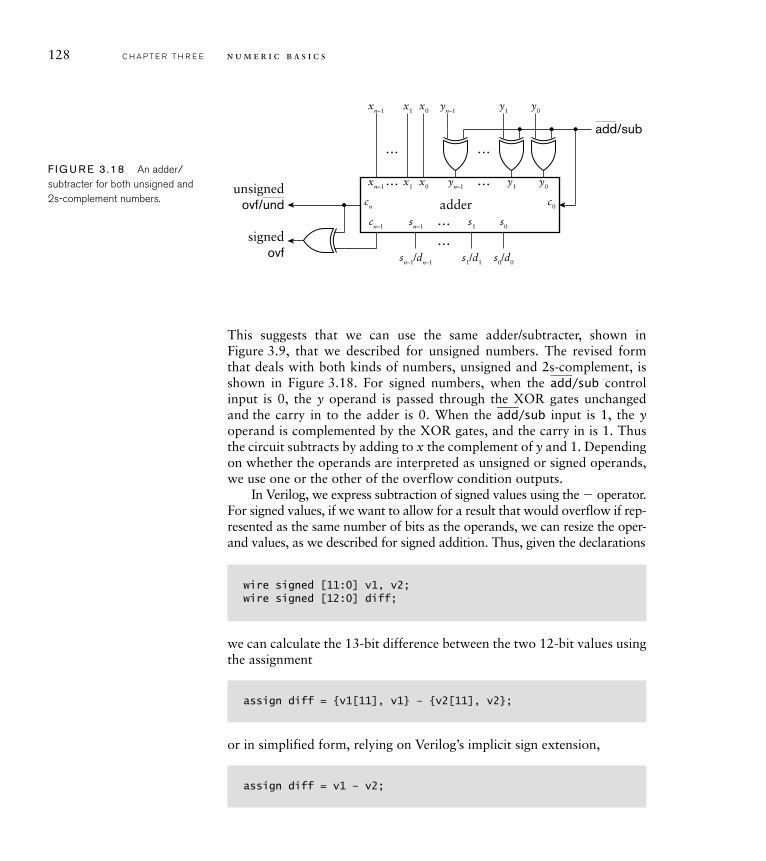
128 C H A P T E R T H R E E n u m e r i c b a s i c s
y0y1yn–1
y0
c0cn
y1yn–1
…
…
…
…
x0x1xn–1
x0x1xn–1
… s0s1sn–1
sn–1/dn–1 s1/d1 s0/d0
…
cn–1
adder
add/sub
unsignedovf/und
signedovf
F I G U R E 3 .18 An adder/subtracter for both unsigned and 2s-complement numbers.
This suggests that we can use the same adder/subtracter, shown in Figure 3.9, that we described for unsigned numbers. The revised form that deals with both kinds of numbers, unsigned and 2s-complement, is shown in Figure 3.18. For signed numbers, when the
__ add /sub control
input is 0, the y operand is passed through the XOR gates unchanged and the carry in to the adder is 0. When the
__ add /sub input is 1, the y
operand is complemented by the XOR gates, and the carry in is 1. Thus the circuit subtracts by adding to x the complement of y and 1. Depending on whether the operands are interpreted as unsigned or signed operands, we use one or the other of the overflow condition outputs.
In Verilog, we express subtraction of signed values using the � operator. For signed values, if we want to allow for a result that would overflow if rep-resented as the same number of bits as the operands, we can resize the oper-and values, as we described for signed addition. Thus, given the declarations
wire signed [11:0] v1, v2;wire signed [12:0] diff;
we can calculate the 13-bit difference between the two 12-bit values using the assignment
assign diff = {v1[11], v1} – {v2[11], v2};
or in simplified form, relying on Verilog’s implicit sign extension,
assign diff = v1 – v2;
Again, a Verilog model that represents the difference using the same number of bits as the operands and that derives the overflow condition is somewhat more involved. Since x�y is the same as x� (�y), and the sign of �y is the complement of the sign of y (except when y is zero), we can work out the overflow condition by examining sign bits in a way similar to that for addition. We just need to use the logical negation of the sign bit of y in the overflow expression. Thus, for the declarations
wire signed [7:0] x, y, z;wire ovf;
we can write the following assignments to derive the required difference and overflow condition bit:
assign z = x – y;assign ovf = ~x[7] & y[7] & z[7] | x[7] & ~y[7] & ~z[7];
The case of y being zero is handled correctly by this expression, since in that case, the result z is the same as x, and so the sign of z is the same as the sign of x.
A further case to consider is subtraction of two unsigned numbers to give a signed result, rather than underflowing when the difference is negative. In order to determine the size to use for the result, we can con-sider the range of possible result values. Suppose we are subtracting n-bitunsigned values. The greatest result arises from subtraction of zero from the greatest unsigned value, giving 2n � 1. The least (most negative) result arises from subtraction of 2n � 1 from zero, giving �2n � 1. This range is encompassed by a result with n� 1 bits. So the simplest way to express the subtraction is to zero extend the operands by one bit, treat them as signed, and then apply the signed subtraction operation. In Verilog, given 8-bit operands and a 9-bit result declared as
wire [7:0] v1, v2;wire signed [8:0] diff;
we could write the subtraction as
assign diff = $signed({1'b0, v1}) – $signed({1'b0, v2});
3.2 Signed Integers C H A P T E R T H R E E 129
130 C H A P T E R T H R E E n u m e r i c b a s i c s
Other Arithmetic Operations on Signed Integers
As part of our examination of unsigned integers, we saw that we could use simplified forms of adder and subtracter to implement the increment and decrement operations. The same argument applies to incrementing and decrementing 2s-complement signed integers. However, we won’t go into the details here. As with unsigned integers, we can use the � operatorin Verilog models to add 1 to a signed value to increment, and use the � operator to subtract 1 to decrement the value.
Comparison of signed integers is also done similarly to comparison of unsigned integers. The main difference arises from the negative weight for the sign bit. Hence, instead of using xn� 1 �
___yn� 1 to compare the most
significant bits in the comparator for x�y, we substitute___xn� 1 �yn� 1 to
compare the sign bits. This follows, since a nonnegative number, with a sign bit of 0 is greater than a negative number with a sign bit of 1. We make the corresponding adjustment in a comparator for xy. The Ver-ilog comparison operators, , �, �, and ��, all work on signed values in an analogous way to unsigned integers.
Scaling a signed integer by a constant power of 2 is slightly different for signed integers than for unsigned integers. Multiplying by 2k involves shifting to the left by k positions and appending k bits of 0 to the least significant end. This is the same logical shift left operation that we say for unsigned numbers. However, if we need to represent the result in the same number of bits as the original unscaled number, we must truncate using the resizing rules for 2s-complement described earlier. Thus, the truncated bits must all be the same as the original sign bit, and the sign of the result must also have that same sign. Dividing by 2k involves shifting the bits right by k positions, discarding the k least significant bits and appending k copies of the original sign bit at the most significant end. This operation is called an arithmetic shift right. It differs from a logical shift right in the replication of the sign bit instead of filling with 0 bits. Proof that these operations correctly implement scaling is left to Exercise 3.54.
In Verilog, we can apply the and ��� operators to signed oper-ands. The operator, like the operator, performs a logical shift left, but the ��� operator performs an arithmetic shift right. For exam-ple, if the signed net or variable s has the value 11110011, representing the value �1310, the Verilog expression
s <<< 2
would yield the value 11001100, representing the value �5210. The expression
s >>> 2
would yield the value 11111100, representing the value �410.
The final operation that we discussed in the context of unsigned integers was multiplication. Extending the multiplier design that we described there to deal with 2s-complement signed numbers gets quite complicated, since we need to deal with sign extension within partial products. In real designs, signed multipliers are based on transformations of this basic approach to reduce the amount of circuitry required and to improve performance. We will not go into detail here, but refer to the books listed in Section 3.6, Further Reading. In any case, using our design methodology, we can simply express multiplication in Verilog using the *operator on signed values and let synthesis CAD tools choose an appro-priate multiplier circuit to use.
1. What is the difference in representation between unsigned binary and 2s-complement signed binary?
2. What is the range of values that can be represented using 12-bit 2s-complement signed binary form?
3. Write a Verilog declaration for a net that represents a number in the range �512 to 511 in 2s-complement signed form.
4. Resize the 2s-complement numbers 01110001 and 11110011 to 12 bits and 6 bits. In each case, does the result correctly represent the same value as the original?
5. Negate the 2s-complement signed number 11110010.
6. How is a signed adder used to perform signed subtraction?
7. How is a 2s-complement signed number multiplied by 16? How is it divided by 16?
3.3 F I X E D - P O I N T N U M B E R S
While many applications deal with integer data, there is a growing list of applications that also deal with fractional numeric data. Many such appli-cations involve digital signal processing, in which time-varying analog signals are sampled, converted to a digital representation and subject to numerical operations. For example, most modern audio devices deal with sampled audio signals and perform operations such as filtering, amplifi-cation and equalization. The audio samples are approximations to real numbers within a given range. The circuits representing and operating upon the samples need to deal with fractional values, that is, values that lie between integers. In this section, we will introduce the notion of fixed-point representation of nonintegral values.
3.3.1 C O D I N G F I X E D - P O I N T N U M B E R S
Suppose we need to represent numeric values that lie in the range �12.0to �12.0. Since there are an infinite number of real numbers in that range,
K N O W L E D G E T E S T Q U I ZK N O W L E D G E T E S T Q U I Z
3.3 Fixed-Point Numbers C H A P T E R T H R E E 131
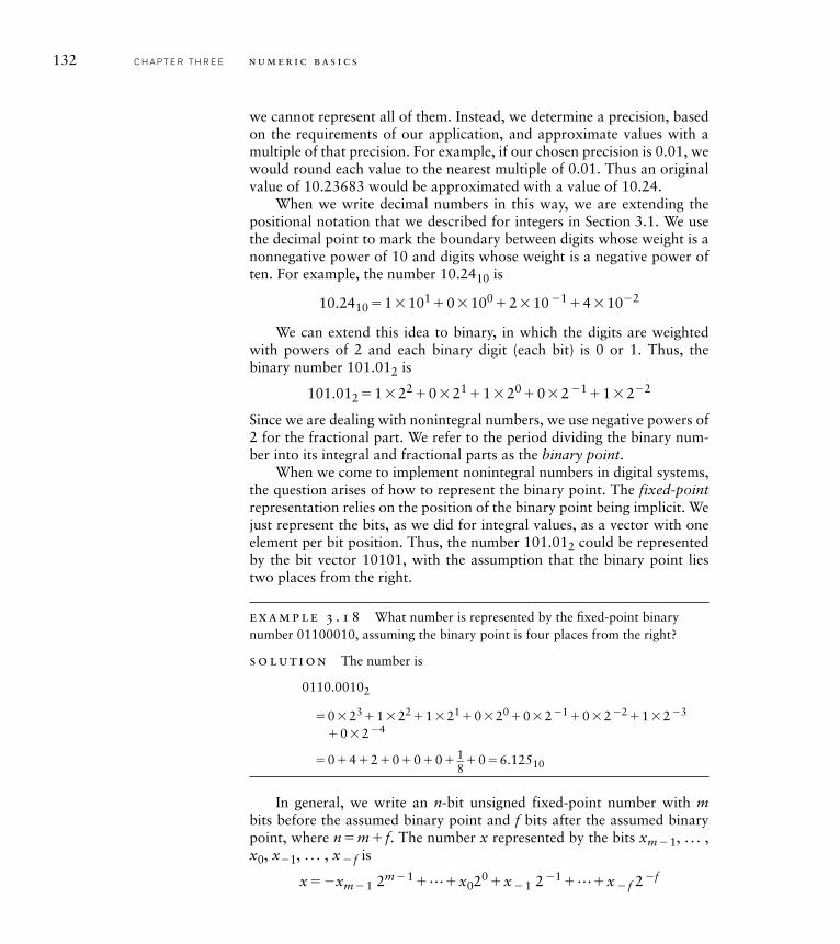
132 C H A P T E R T H R E E n u m e r i c b a s i c s
we cannot represent all of them. Instead, we determine a precision, based on the requirements of our application, and approximate values with a multiple of that precision. For example, if our chosen precision is 0.01, we would round each value to the nearest multiple of 0.01. Thus an original value of 10.23683 would be approximated with a value of 10.24.
When we write decimal numbers in this way, we are extending the positional notation that we described for integers in Section 3.1. We use the decimal point to mark the boundary between digits whose weight is a nonnegative power of 10 and digits whose weight is a negative power of ten. For example, the number 10.2410 is
10.2410 � 1 � 101 � 0 � 100 � 2 � 10 �1 � 4 � 10�2
We can extend this idea to binary, in which the digits are weighted with powers of 2 and each binary digit (each bit) is 0 or 1. Thus, the binary number 101.012 is
101.012 � 1 � 22 � 0 � 21 � 1 � 20 � 0 � 2 �1� 1 � 2�2
Since we are dealing with nonintegral numbers, we use negative powers of 2 for the fractional part. We refer to the period dividing the binary num-ber into its integral and fractional parts as the binary point.
When we come to implement nonintegral numbers in digital systems, the question arises of how to represent the binary point. The fixed-pointrepresentation relies on the position of the binary point being implicit. We just represent the bits, as we did for integral values, as a vector with one element per bit position. Thus, the number 101.012 could be represented by the bit vector 10101, with the assumption that the binary point lies two places from the right.
example 3 .18 What number is represented by the fi xed-point binary number 01100010, assuming the binary point is four places from the right?
solut ion The number is
0110.00102
�0� 23 � 1 � 22 � 1 � 21 � 0 � 20 � 0 � 2 �1 � 0 � 2 �2 � 1 � 2 �3
� 0 � 2 �4
� 0 � 4 � 2 � 0 � 0 � 0 � 1 8
� 0 � 6.12510
In general, we write an n-bit unsigned fixed-point number with mbits before the assumed binary point and f bits after the assumed binary point, where n�m� f. The number x represented by the bits xm� 1, . . . , x0, x�1, . . . , x � f is
x��xm� 1 2m� 1 � . . .�x020 �x � 1 2 �1 � . . .�x � f 2 �f
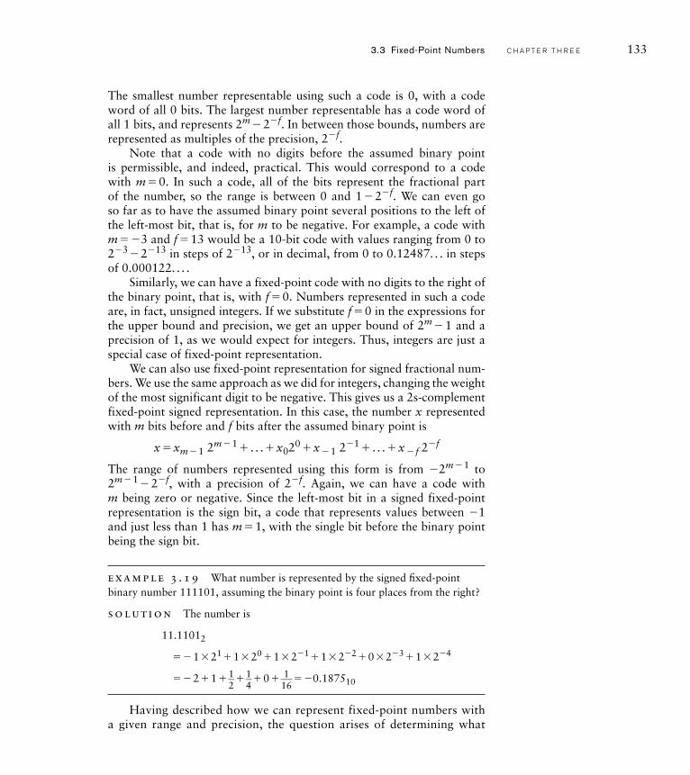
The smallest number representable using such a code is 0, with a code word of all 0 bits. The largest number representable has a code word of all 1 bits, and represents 2m � 2�f. In between those bounds, numbers are represented as multiples of the precision, 2�f.
Note that a code with no digits before the assumed binary point is permissible, and indeed, practical. This would correspond to a code with m� 0. In such a code, all of the bits represent the fractional part of the number, so the range is between 0 and 1 � 2�f. We can even go so far as to have the assumed binary point several positions to the left of the left-most bit, that is, for m to be negative. For example, a code with m��3 and f� 13 would be a 10-bit code with values ranging from 0 to 2�3 � 2�13 in steps of 2�13, or in decimal, from 0 to 0.12487. . . in steps of 0.000122. . . .
Similarly, we can have a fixed-point code with no digits to the right of the binary point, that is, with f� 0. Numbers represented in such a code are, in fact, unsigned integers. If we substitute f� 0 in the expressions for the upper bound and precision, we get an upper bound of 2m � 1 and a precision of 1, as we would expect for integers. Thus, integers are just a special case of fixed-point representation.
We can also use fixed-point representation for signed fractional num-bers. We use the same approach as we did for integers, changing the weight of the most significant digit to be negative. This gives us a 2s-complement fixed-point signed representation. In this case, the number x represented with m bits before and f bits after the assumed binary point is
x�xm� 1 2m� 1 � . . . �x020 �x � 1 2�1 � . . . �x � f 2�f
The range of numbers represented using this form is from �2m� 1 to 2m� 1 � 2�f, with a precision of 2�f. Again, we can have a code with m being zero or negative. Since the left-most bit in a signed fixed-point representation is the sign bit, a code that represents values between �1and just less than 1 has m� 1, with the single bit before the binary point being the sign bit.
example 3 .19 What number is represented by the signed fi xed-point binary number 111101, assuming the binary point is four places from the right?
solut ion The number is
11.11012
�� 1 � 21 � 1 � 20 � 1 � 2�1 � 1 � 2�2 � 0 � 2�3 � 1 � 2�4
�� 2 � 1 �1� 2
�1� 4
� 0 � 1� 16
��0.187510
Having described how we can represent fixed-point numbers with a given range and precision, the question arises of determining what
3.3 Fixed-Point Numbers C H A P T E R T H R E E 133
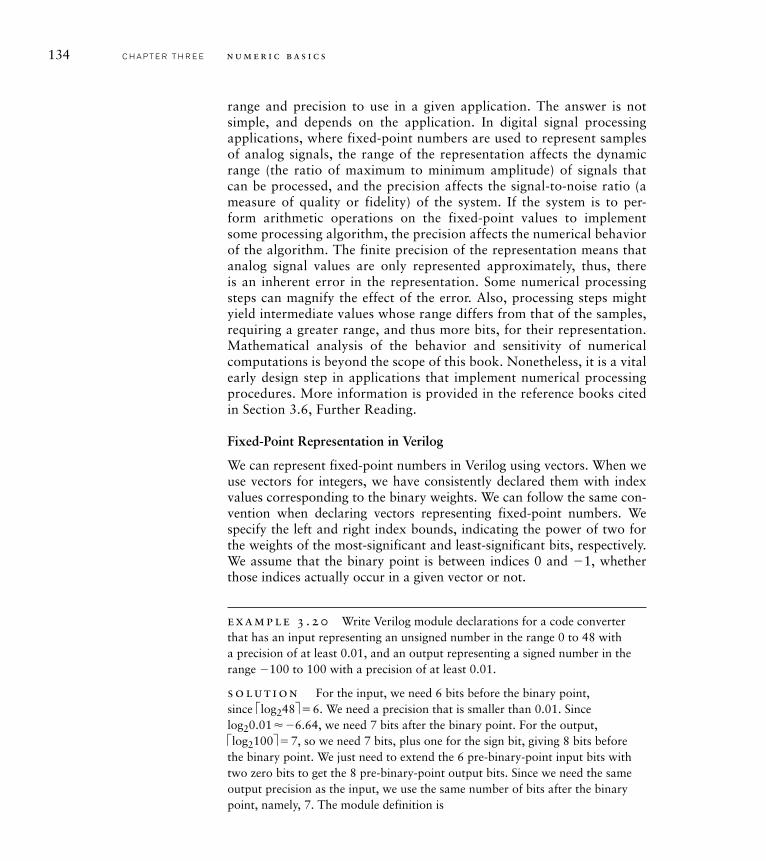
134 C H A P T E R T H R E E n u m e r i c b a s i c s
range and precision to use in a given application. The answer is not simple, and depends on the application. In digital signal processing applications, where fixed-point numbers are used to represent samples of analog signals, the range of the representation affects the dynamic range (the ratio of maximum to minimum amplitude) of signals that can be processed, and the precision affects the signal-to-noise ratio (a measure of quality or fidelity) of the system. If the system is to per-form arithmetic operations on the fixed-point values to implement some processing algorithm, the precision affects the numerical behavior of the algorithm. The finite precision of the representation means that analog signal values are only represented approximately, thus, there is an inherent error in the representation. Some numerical processing steps can magnify the effect of the error. Also, processing steps might yield intermediate values whose range differs from that of the samples, requiring a greater range, and thus more bits, for their representation. Mathematical analysis of the behavior and sensitivity of numerical computations is beyond the scope of this book. Nonetheless, it is a vital early design step in applications that implement numerical processing procedures. More information is provided in the reference books cited in Section 3.6, Further Reading.
Fixed-Point Representation in Verilog
We can represent fixed-point numbers in Verilog using vectors. When we use vectors for integers, we have consistently declared them with index values corresponding to the binary weights. We can follow the same con-vention when declaring vectors representing fixed-point numbers. We specify the left and right index bounds, indicating the power of two for the weights of the most-significant and least-significant bits, respectively. We assume that the binary point is between indices 0 and �1, whether those indices actually occur in a given vector or not.
example 3 .20 Write Verilog module declarations for a code converter that has an input representing an unsigned number in the range 0 to 48 with a precision of at least 0.01, and an output representing a signed number in the range �100 to 100 with a precision of at least 0.01.
solut ion For the input, we need 6 bits before the binary point, since élog248ù � 6. We need a precision that is smaller than 0.01. Since log20.01��6.64, we need 7 bits after the binary point. For the output, élog2100ù � 7, so we need 7 bits, plus one for the sign bit, giving 8 bits before the binary point. We just need to extend the 6 pre-binary-point input bits with two zero bits to get the 8 pre-binary-point output bits. Since we need the same output precision as the input, we use the same number of bits after the binary point, namely, 7. The module definition is
module fixed_converter ( input [5:–7] in,output signed [7:–7] out );
assign out = {2'b0, in};
endmodule
In our discussion of integers, we mentioned that Verilog provides the type integer for abstract representation of numbers. Unfortunately, Veri-log does not provide a corresponding type for abstract representation of fixed-point numbers. Abstract fixed-point types could, in principle, be included in the language, as has been done in the Ada programming lan-guage, for example. While we might hope that abstract fixed-point types might be included in a future version of Verilog as applications become more common, for now, we will just make use of the vector types.
For testbenches in Verilog, however, we can make use of a built-in type real. We can declare a variable (but not a net) to be of this type as follows:
real x;
Real variables are actually represented using floating-point format, described in Section 3.4. However, we can use them for nonintegral val-ues to be applied to the inputs or checked at the outputs of models using fixed-point representation. Some examples are
real r1, r2;wire [5:-16] x, y;wire [8:-14] z;
r1 <= $itor(x)/2**16;r2 <= r1 / ($itor(y)/2**16);z <= $rtoi(r2 * 2**14);
The conversion function $itor used here converts from a vector value, interpreted as an integer, to a real-number value. The scaling is required, since our actual interpretation of the vector is a fixed-point value. The conversion function $rtoi works in the reverse direction, from a real-number value to a vector interpreted as an integer. Again, scaling is required to take account of our actual interpretation of the vector as a fixed-point value.
3.3 Fixed-Point Numbers C H A P T E R T H R E E 135
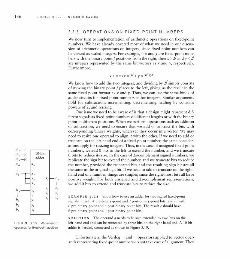
136 C H A P T E R T H R E E n u m e r i c b a s i c s
3.3.2 O P E R AT I O N S O N F I X E D - P O I N T N U M B E R S
We now turn to implementation of arithmetic operations on fixed-point numbers. We have already covered most of what we need in our discus-sion of arithmetic operations on integers, since fixed-point numbers can be viewed as scaled integers. For example, if x and y are fixed-point num-bers with the binary point f positions from the right, then x � 2f and y � 2f are integers represented by the same bit vectors as x and y, respectively. Furthermore,
x � y � (x � 2f � y � 2f)/2f
We know how to add the two integers, and dividing by 2f simply consists of moving the binary point f places to the left, giving us the result in the same fixed-point format as x and y. Thus, we can use the same kinds of adder circuits for fixed-point numbers as for integers. Similar arguments hold for subtraction, incrementing, decrementing, scaling by constant powers of 2, and resizing.
One issue we need to be aware of is that a design might represent dif-ferent signals as fixed-point numbers of different lengths or with the binary point in different positions. When we perform operations such as addition or subtraction, we need to ensure that we add or subtract the bits with corresponding binary weights, wherever they occur in a vector. We may need to resize one operand to align it with the other. If we need to add or truncate on the left-hand end of a fixed-point number, the same consider-ations apply for resizing integers. Thus, in the case of unsigned fixed-point numbers, we add 0 bits to the left to extend the number, and we truncate 0 bits to reduce its size. In the case of 2s-complement signed numbers, we replicate the sign bit to extend the number, and we truncate bits to reduce the number, provided the truncated bits and the resulting sign bit are all the same as the original sign bit. If we need to add or truncate on the right-hand end of a number, things are simpler, since the right-most bits all have positive weight. For both unsigned and 2s-complement representations, we add 0 bits to extend and truncate bits to reduce the size.
example 3 .21 Show how to use an adder for two signed fi xed-point signals: a, with 4 pre-binary-point and 7 post-binary-point bits, and b, with 6 pre-binary-point and 4 post-binary-point bits. The result c should have 6 pre-binary-point and 4 post-binary-point bits.
solut ion The operand a needs to be sign extended by two bits on the left-hand end and can be truncated by three bits on the right-hand end. A 10-bit adder is needed, connected as shown in Figure 3.19.
Unfortunately, the Verilog � and � operators applied to vector oper-ands representing fixed-point numbers do not take care of alignment. They
x0
10-bitadder
……
a–4
a–5
a–6
a–7
x7a3
x8
x9
y0……
b–4
y7b3
b4
b5
c–4
c3
c4
c5
…
y8
y9
s0…s7
s8
s9
F I G U R E 3 .19 Alignment of operands for fi xed-point addition.
just perform the operations assuming the right-most bits of the operands are the corresponding least significant bits. If both operands are declared with the same index bounds, the operations are performed correctly for the fixed-point interpretation of the values. If, however, the index bounds are not the same, we need to extend or truncate both ends of the operands to make sure that the assumed binary points align.
example 3 .22 Write Verilog declarations and an assignment to perform the addition described in Example 3.21.
solut ion The declarations for the nets a, b and c are
wire signed [3:-7] a;wire signed [5:-4] b, c;
We could try the following assignment as a first attempt:
assign c = a + b;
Since a is 11 bits and b is 10 bits, the � operator would sign extend b to 11 bits and perform an 11-bit addition. The implicit binary points would be misaligned by three places. To correct this, we need to sign extend the value of a by 2 bits, and to truncate the 3 least signficant bits of a. We can use a part select to perform the truncation, but the result of a part select is treated as unsigned in Verilog. We can use the $signed conversion operation to re-interpret it as signed. The following assignment incorporates these corrections:
assign c = {{2{a[3]}}, $signed(a[3:–4])} + b;
Another related issue to be aware of is the position of the binary point in the result of a multiplication. We can appeal to the way in which we do multiplication of decimals for an analogy. Suppose, for example, that we wish to multiply 23.76 by 3.128. We first multiply the digits without regard to the decimal points to get 7432128. We then add the number of post-decimal digits in the operands, namely, 2 and 3, to get the number of post-decimal digits in the result, namely, 5. Thus the product is 74.32128.
By analogy, multiplying two fixed-point binary numbers with m1 and m2pre-binary-point bits and f1 and f2 post-binary-point bits, respectively, gives us a product with m1�m2 pre-binary-point bits and f1� f2 post-binary-point bits. For example, multiplying 1.1012 by 10.12 gives 100.00012. If
3.3 Fixed-Point Numbers C H A P T E R T H R E E 137

138 C H A P T E R T H R E E n u m e r i c b a s i c s
we are to use the Verilog * operator to produce a product of this length, we must extend each operand on the left to the final product size.
1. How is a nonnegative number x represented as a sum of powers of 2 in fi xed-point form?
2. What range of values can be represented as signed fi xed-point numbers with m pre-binary-point bits and f post-binary-point bits?
3. Write a Verilog declaration for a net x, not to represent numbers in the range 0.0 to 359.9 with a precision of 0.1.
4. Write a Verilog assignment to subtract the value of a net s2 from the value of a net s1, where both are of type wire [7:–7], to get a result net s3 of the same type. No overfl ow detection is required.
5. How many bits are required for the product of two fi xed-point numbers with 5 pre-binary-point bits and 9 post-binary-point bits?
3.4 F LO AT I N G - P O I N T N U M B E R S
The final number representation that we will discuss in this chapter is floating-point, which is another representation for approximating real numbers. They allow for representation of a greater range of numbers than a fixed-point representation with the same number of bits. However, implementation of arithmetic operations is considerably more complex. Indeed, most circuits for floating-point arithmetic are not combinational, since they would otherwise be too complex and reduce overall system per-formance. Since we have deferred detailed discussion of sequential circuit design to a later chapter, we will not go into circuits for floating-point arithmetic here. For completeness of our survey of numeric representa-tions in this chapter, we will just introduce floating-point format. Unfor-tunately, Verilog only provides rudimentary features for dealing with floating-point numbers. They are not sufficient for modeling floating-point circuits, so we will not discuss them here.
3.4.1 C O D I N G F LO AT I N G - P O I N T N U M B E R S
Floating-point representation in digital systems is based on the same ideas as scientific notation for decimal numbers. We can write numbers that are very small or very large as the product of a fixed-point decimal fraction and a power of 10. This saves us from writing long strings of leading or trailing zeros and makes the number much easier to read and understand. Exam-ples of numbers expressed in scientific notation are 6.02214199 � 1023
(Avogadro’s number) and 1.60217653 � 10�19 (the charge, in Coulombs, of an electron). We call the fractional part before the � sign the mantissaand the power to which 10 is raised the exponent.
K N O W L E D G E T E S T Q U I ZK N O W L E D G E T E S T Q U I Z
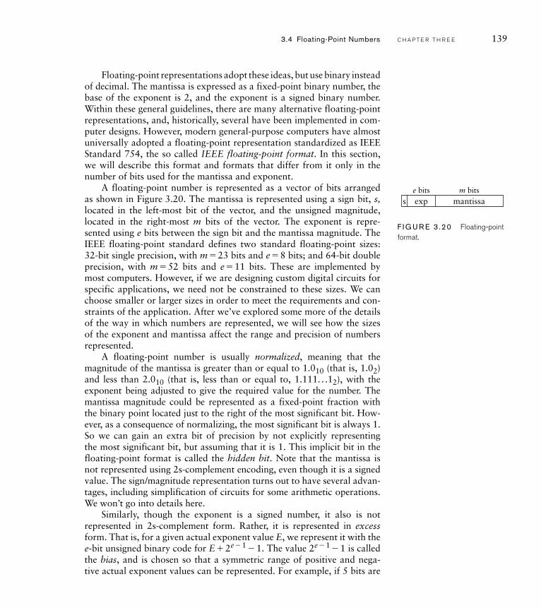
Floating-point representations adopt these ideas, but use binary instead of decimal. The mantissa is expressed as a fixed-point binary number, the base of the exponent is 2, and the exponent is a signed binary number. Within these general guidelines, there are many alternative floating-point representations, and, historically, several have been implemented in com-puter designs. However, modern general-purpose computers have almost universally adopted a floating-point representation standardized as IEEE Standard 754, the so called IEEE floating-point format. In this section, we will describe this format and formats that differ from it only in the number of bits used for the mantissa and exponent.
A floating-point number is represented as a vector of bits arranged as shown in Figure 3.20. The mantissa is represented using a sign bit, s, located in the left-most bit of the vector, and the unsigned magnitude, located in the right-most m bits of the vector. The exponent is repre-sented using e bits between the sign bit and the mantissa magnitude. The IEEE floating-point standard defines two standard floating-point sizes: 32-bit single precision, with m � 23 bits and e � 8 bits; and 64-bit double precision, with m � 52 bits and e � 11 bits. These are implemented by most computers. However, if we are designing custom digital circuits for specific applications, we need not be constrained to these sizes. We can choose smaller or larger sizes in order to meet the requirements and con-straints of the application. After we’ve explored some more of the details of the way in which numbers are represented, we will see how the sizes of the exponent and mantissa affect the range and precision of numbers represented.
A floating-point number is usually normalized, meaning that the magnitude of the mantissa is greater than or equal to 1.010 (that is, 1.02) and less than 2.010 (that is, less than or equal to, 1.111. . .12), with the exponent being adjusted to give the required value for the number. The mantissa magnitude could be represented as a fixed-point fraction with the binary point located just to the right of the most significant bit. How-ever, as a consequence of normalizing, the most significant bit is always 1.So we can gain an extra bit of precision by not explicitly representing the most significant bit, but assuming that it is 1. This implicit bit in the floating-point format is called the hidden bit. Note that the mantissa is not represented using 2s-complement encoding, even though it is a signed value. The sign/magnitude representation turns out to have several advan-tages, including simplification of circuits for some arithmetic operations. We won’t go into details here.
Similarly, though the exponent is a signed number, it also is not represented in 2s-complement form. Rather, it is represented in excess form. That is, for a given actual exponent value E, we represent it with the e-bit unsigned binary code for E � 2e � 1 � 1. The value 2e � 1 � 1 is called the bias, and is chosen so that a symmetric range of positive and nega-tive actual exponent values can be represented. For example, if 5 bits are
se bits m bits
exp mantissa
F I G U R E 3 .20 Floating-point format.
3.4 Floating-Point Numbers C H A P T E R T H R E E 139
used for the exponent, the bias would be 24 � 1 � 15, that is, 011112. An actual exponent value of 3 would be represented using the 5-bit unsigned binary code for 3 � 15 � 18, that is 100102. The reason for using excess coding is that all exponent codes are unsigned. Given the position of the exponent within a floating-point code word, and the fact that numbers with smaller exponents are smaller than numbers with larger exponents (due to normalization), floating-point numbers can be compared using the same hardware as for comparing integers. This is a useful trick for saving cost and execution time in floating-point arithmetic hardware.
Let’s now consider the range and precision of values that can be represented using floating-point format. As with fixed-point numbers, the range and precision are important factors that influence the numeri-cal behavior of computations. The range of values is determined by the length of the exponent, since the most positive exponent determines the largest value and the most negative exponent determines the smallest value. The IEEE floating-point format reserves two exponent encodings for special purposes: the largest encoding, 2e� 1, with all 1 bits; and the smallest encoding, with all 0 bits. We will return to these shortly. Setting them aside, the smallest exponent has an encoding of 1, representing an actual exponent value of �2e� 1� 2. Putting this together with the smallest mantissa magnitude of 1.0 gives us the smallest representable value of�1.0� 2�2e� 1� 2. The largest exponent has an encoding of 2e� 2, repre-senting an actual exponent value of 2e� 1� 1. Putting this together with the largest mantissa magnitude of just under 2.0 gives us the largest rep-resentable value of just under � 2.0� 2 2
e� 1 � 1, that is, � 2 2e� 1. For IEEE
single-precision format, this corresponds to a range of approximately �1.2� 10� 38 to �3.4� 1038, and for IEEE double-precision format, a range of approximately �2.2� 10� 308 to �1.8� 10308. A custom floating-point representation with a 5-bit exponent, on the other hand, would give us a range of approximately �6.1� 10�5 to �6.6� 104.
When considering the precision of floating-point numbers, we usuallytalk about relative precision, since absolute precision varies with the exponent. The relative precision is determined by the number of bits in the mantissa magnitude. All of the bits are significant, since there are no leading zeros in the mantissa (taking into account the hidden bit). So the relative precision remains the same across the full range of values, and is approximately 2�m. Another way of thinking about precision is to specify the number of significant decimal digits, which is approximately m� log102, that is m� 0.3 digits. For example, IEEE single-precision for-mat gives a precision of approximately 7 decimal digits, and IEEE double-precision format gives approximately 16 decimal digits. A custom format with 16 bits of mantissa magnitude would give a precision of approxi-mately 5 decimal digits.
140 C H A P T E R T H R E E n u m e r i c b a s i c s
We can return now to the special exponent encodings that we mentioned above. First, the smallest exponent encoding, all zeros, is used for denormalnumbers, in which the hidden bit is 0. The actual exponent is still repre-sented using excess form, and so has a value of �2e� 1 � 1. Thus, denormal numbers are all smaller in magnitude than the smallest normalized number, though they have fewer significant bits. They allow for gradual under-flow in a computation, where the results diminish toward 0.0 once thelimit of precision has been reached. This feature of the representation improves the numerical behavior of some algorithms. If all the mantissabits in a denormal number are 0, we get �0.0� 2� 2
e� 1 � 1. Thus, there are two alternate representations for 0.0, one with a sign bit of 0 and the other with a sign bit of 1. The IEEE standard specifies that a zero result in most cases be represented by the nonnegative version, but that in any case, the two versions should be deemed equal.
The other special exponent encoding, all 1s, has two uses. If the man-tissa magnitude bits are all 0 (not counting the hidden bit), the number represents an infinite value. The value of the sign bit determines whether it is a positive or negative infinity. Operations that overflow generally yield an infinite result, which is maintained in subsequent computations. This avoids having to check for overflow until completion of a multistep computation, thus improving performance. If the exponent encoding is all 1s and the mantissa magnitude is other than all 0s, the value is said to represent not a number (NaN). NaN results arise from computations such as division of 0 by 0, and can also be maintained through a multistep computation.
In addition to the representation for floating-point numbers, the IEEE standard also specifies how arithmetic operations are to be performed, provides options for specifying how operations are to be rounded, and specifies the conditions under which exceptions may occur. (A system may abort a computation or take recovery action when an exception occurs.) The details are beyond the scope of this book, but can be found in the Further Reading references.
For a given number of bits of representation, floating-point representa-tion can give a larger range of values than fixed-point, albeit at the expense of precision. The choice between floating-point and fixed-point in a given application will depend largely on the range of values that must be repre-sented, both for the input and output signals, as well as for intermediate results during computation. There is also a trade-off with the complexity of circuits needed to perform the computations. Fixed-point circuits are gen-erally simpler, but if significantly more bits are needed to get the required range, the circuits may consume more area. In many cases, the choice will only be made after thorough exploration of the numerical behavior of the computations to be performed and comparison of implementation
3.4 Floating-Point Numbers C H A P T E R T H R E E 141
142 C H A P T E R T H R E E n u m e r i c b a s i c s
complexities of alternate representations. This exploration will usually be performed by a system architect early in the development process. The result of the exploration will be a design specification that includes details of number representations to be used within the system. In a circuit that is customized for a particular application, a floating-point representation can use exponent and mantissa sizes other than those defined by the IEEE standard, thus reducing cost and potentially improving performance.
1. Express the number 4.510 in fl oating-point format with 5 bits of exponent and 12 bits of mantissa magnitude.
2. What values are represented by the following bit vectors, interpreted in fl oating-point format with 4 bits of exponent and 11 bits of mantissa magnitude: 0000000000000000, 0111100000000000 and 0100010000000000?
3. Determine the minimum number of exponent and mantissa bits required to represent a fl oating-point value in the range �100 to 100 with a precision of at least 4 decimal digits.
K N O W L E D G E T E S T Q U I ZK N O W L E D G E T E S T Q U I Z
3.5 C H A P T E R S U M M A R Y
A nonnegative integer x less than or equal to 2n � 1 is represented in n-bit unsigned binary form as
x�xn� 1 2n� 1 �xn� 2 2
n� 2 � . . .�x020
A signed integer x between �2n� 1 and 2n� 1 � 1 inclusive is repre-sented in n-bit 2s-complement form as
x��xn� 1 2n� 1 �xn� 2 2
n� 2 � . . .�x020
Octal (base 8) and hexadecimal (base 16) are shorthand codes for binary codes.
Unsigned and signed integers are modeled in Verilog using vector values, or using the type integer. For signed integers the keyword signed is used in the net or variable declaration. Arithmetic opera-tors can be used for these types.
An unsigned number is zero-extended by adding 0s to the left, and is truncated by discarding leading 0s. A 2s-complement signed number is sign-extended by replicating the sign bit to the left, and is trun-cated by discarding leading copies of the sign bit.
Addition of binary-coded integers is performed by an adder circuit. The simplest form of adder is a ripple-carry adder. Fast carry chain, carry-lookahead and other adder structures improve performance at the cost of circuit area and power.
A 2s-complement signed integer is negated by complementing and adding 1.
Subtraction of binary-coded integers can be implemented using an adder by complementing the second operand and setting the carry in to 1.
A magnitude comparator compares two binary-coded integers for equality or inequality (greater than or less than comparison).
Binary-coded integers are multiplied by a power of two by a logical shift left. Unsigned integers are divided by a power of 2 by a logical shift right. 2s-complement signed integers are divided by a power of 2 by an arithmetic shift right.
A combinational multiplier forms partial products by multiplying one operand by each bit of the other operand, then adds the partial products to form the product.
�
�
�
�
�
�
�
�
�
�
�
3.5 Chapter Summary C H A P T E R T H R E E 143
144 C H A P T E R T H R E E n u m e r i c b a s i c s
Gray codes change only in one bit position between adjacent |code words. They are commonly used in electromechanical position sensors.
A fractional number can be represented in fixed-point binary form by assuming a fixed position for the binary point. Arithmetic circuits for integers can be used, since fixed-point numbers can be inter-preted as scaled integers.
Fixed-point numbers are modeled in Verilog using vector values. Arithmetic operators can be used for these types, provided the implicit binary points are properly aligned.
A fractional number can be represented in floating-point binary form with a signed mantissa and an exponent. IEEE format specifies sign/magnitude representation for the mantissa and excess representation for the exponent. Special representations are provided for denormal numbers, infinities and not-a-number values.
Modeling a design using vector types and arithmetic operations allows a synthesis tool to choose arithmetic components optimized for the target fabric, subject to performance requirements and constraints.
3.6 F U R T H E R R E A D I N G
Digital Arithmetic, Miloš D. Ercegovac and Tomás Lang, Morgan Kaufmann Publishers, 2004. A comprehensive reference on numeri-cal representations and algorithms and circuit structures for arith-metic operations.
Understanding Digital Signal Processing, Richard G. Lyons, Prentice Hall, 2001. An introduction to the theory of digital signal process-ing (DSP), including a discussion of the effects of finite fixed-point representation.
IEEE Standard for Binary Floating-Point Arithmetic, IEEE Std 754-1985. This standard defined the representation for single- precision(32-bit) and double-precision (64-bit) and extended-precision floating-point numbers. It also specifies how arithmetic operations on such numbers are to be performed.
e x e rc i s e 3 . 1 Express the following decimal numbers in 8-bit unsigned binary form: 5, 83 and 240.
e x e rc i s e 3 . 2 What decimal numbers are represented by the following 8-bit unsigned binary numbers: 00100101 and 11000000?
�
�
�
�
�
E X E R C I S E SE X E R C I S E S