numerical analysis of high speed droplet impact€¦ · · 2013-01-23plays an important role in...
TRANSCRIPT
Paper No 7th International Conference on Multiphase Flow ICMF 2010, Tampa, FL USA, May 30-June 4, 2010
1
Numerical Analysis of High Speed Droplet Impact
Toshiyuki Sanada*, Keita Ando† and Tim Colonius†
* Department of Mechanical Engineering, Shizuoka University, Hamamatsu, 432-8561, Japan
† Department of Mechanical Engineering, California Institute of Technology, Pasadena, CA 91106, USA [email protected], [email protected] and [email protected]
Keywords: numerical simulation, high-speed, droplet, side jet, target compliance
Abstract When a droplet impacts a solid surface at high speed, the contact periphery expands very quickly and liquid compressibility plays an important role in the initial dynamics and the formation of lateral jets. The high speed impact results in high pressures that can account for the surface erosion. In this study, we numerically investigated a high speed droplet impacts on a solid wall. The multicomponent Euler equations with the stiffened equation of state are computed using a FV-WENO scheme with an HLLC Riemann solver (Johnsen & Colonius 2006) that accurately captures shocks and interfaces. In order to compare the available theories and experiments, 1D, 2D and axisymmetric solutions are obtained. The generated pressures, shock speeds, and the lateral jetting generation are investigated. In addition, the effect of target compliance is evaluated.
Introduction
When a high speed droplet impacts on a solid wall, there is an important initial stage (Lesser & Field 1983) during which the curved liquid surface is compressed and non uniform pressure distribution is generated. This initial stage creates high pressure which is greater than the well-known water hammer pressure,
(1) where p is the generated pressure, ρ is the liquid density, C is the sonic speed of the liquid. The high speed impact can generate high pressure of order GPa, so that the target material is often damaged because the pressure is large enough compared to the yield stress. However, the several models for predicting this pressure have been proposed from theoretical, experimental and numerical studies.
The generalized form of the water hammer relation (1) that accounts for the target compressibility can be written as
(2)
where the subscripts s and l denote solid and water, respectively, is the target compliance defined as the ratio of acoustic impedance between solid and water (liquid droplets). Small values of correspond to stiff material. These 1-dimensional linear theories (1) and (2) may be extended to large Mach number cases using relationship between shock wave velocity and liquid particle velocity (Heymann 1968, Haung et al. 1973).
During the impact of cylindrical or spherical droplets, the dimensionality plays a role to generate complex pressure distributions. Heymann (1969), Lesser (1981) and Field et al. (1985) theoretically estimated that the droplet center pressure can be predicted by the water hammer pressure Eq. (1) but the deformed edge pressure can reach 3 times higher
than the water hammer pressure. They also argued that the pressure inside the cylindrical droplet is higher than in the spherical case, but edge pressure is identical for both cases (Lesser 1981, Field et al. 1985). The experiment of Rochester & Brunton (1979) agrees with their argument, but some experiments show discrepancy. For example, Engel (1955, see Brunton 1966) proposed modified water hammer pressure as,
(3)
where α approaches unity for high impact velocities and the factor of 1/2 is a consequence of the spherical shape of droplet.
In this study, we simulate a high speed droplet impact on a solid wall and focus on the generated pressure. Although Haller et al. (2002) have numerically investigated a droplet impact in detail but they especially focused on jetting time. In addition they have only solved the one case Vi =500 m/s into idealized rigid surface. We change the parameters of the stiffened equation of state and examine the effect of target compliance on this generated pressure due to the droplet impact. Nomenclature
C Speed of sound (ms-1) E Total energy I Identity tensor k Parameter M Mach number p Pressure (Nm-2) P∞ Stiffness constant (Nm-2) t Time (s) u Velocity vector (ms-1) Vi Impact speed (ms-1)
Target compliance

Paper No 7th International Conference on Multiphase Flow ICMF 2010, Tampa, FL USA, May 30-June 4, 2010
2
Greek letters α Coefficient ρ Density (kg m-2) γ Ratio of specific heats (gas) Subsripts cen center i impact l liquid max maximum s solid
Numerical Method
With neglect of surface tension and any diffusions, the
flow is govern by the Euler equations (conservation form):
(4)
where u is the velocity vector, E is the total energy and I is the identity tensor. Flows in one and two dimensions (with and without azimuthal symmetry) are considered. In order to close the Euler equations, we employed the stiffened equation of state (Harlow & Amsden 1971),
(5)
where P∞ is the stiffness constant and P∞ = 0 for gases. In this study we simulate a high pressure due to high speed droplet impact. Such high pressure condition, more specifically at pressure which are large compare to the yield stress, solid substance behave essentially as compressible fluids (Tompson 1988); hence even the solid dynamics may be described by the constitutive equation for the fluids. γ and P∞ were chosen from the literature. In the preliminary calculation test problem, we used those from Chen & Liang (2008). For the droplet impact problem we took those from Saurel et al. (1999) and Haller et al. (2002). The parameters used are summarized in Tables 1 and 2.
A third-order WENO scheme with an HLLC Riemann solver (Johnsen & Colonius 2006) that accurately captures shocks and interfaces was used to solve the system. A third-order TVD Runge-Kutta scheme (Shu & Osher 1988; Gottlieb & Shu 1998) was employed to march the equations forward in time. Note that this method has been shown to accurately resolve shock-bubble interaction problems (Johnsen & Colonius 2009).
Table 1: Stiffened EOS parameters* for preliminary test.
ρ [kg/m3] p [105 Pa]
γ P∞ [109 Pa]
air (at rest) 1.2 1 1.4 0
air (behind shock wave) 2.212 2.354 1.4 0
water 1000 1 1.932 1.1645
* Chen & Liang (2008) Table 2: Stiffened EOS and target compliance parameters for droplet impact problems.
ρ
[kg/m3] γ P∞
[109 Pa] C
[m/s]
Uranium/Rhodium* 17204 3.53 36.6 2740 0.04
Epoxy/ Spinel* 2171 3.47 5.98 3090 0.26
Water† 1000 4.4 0.613 1750 1.00
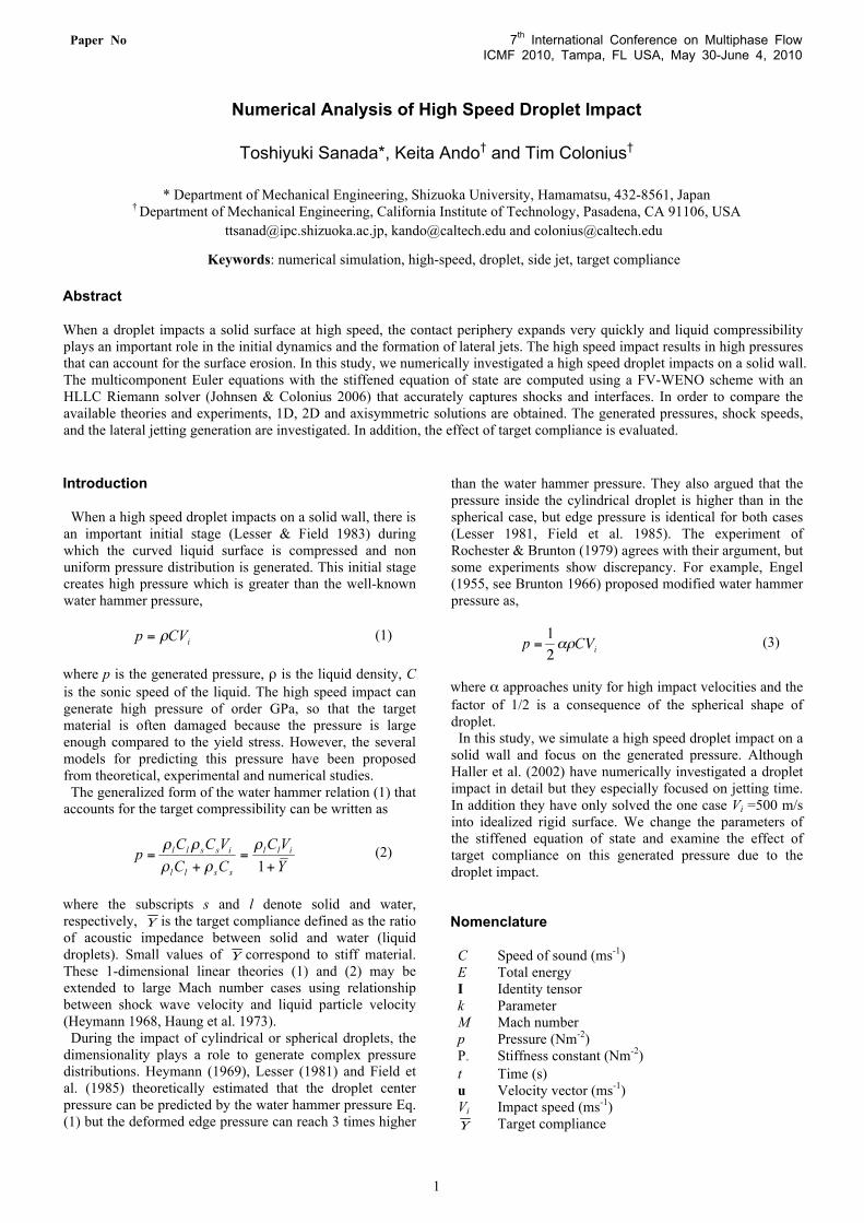
* Saurel et al. (1999), † Haller et al. (2002) (a) preliminary test (droplet - shock interaction) (b) droplet impact problem Figure 1: Schematic of calculation domain.
Paper No 7th International Conference on Multiphase Flow ICMF 2010, Tampa, FL USA, May 30-June 4, 2010
3
The computational domain is shown in Fig. 1. Fig. 1 (a) shows the preliminary test case. In this calculation, the condition was set to be same as that of Chen & Liang (2008). This condition is corresponding to the experiment of Igra & Takayama (1999, 2001). The Mach number for the incident planar shock wave was 1.47. A uniform grid with 800 × 800 points was used.
Figure 1 (b) shows the schematic of droplet impact problems. In this simulation, we consider a moving solid material that impacts a stationary droplet. This replicates the experiment of Camus (1971). Hence in the computational domain, there are a droplet, a shock front in air and a solid component, and the solid impact to the droplet with the particle (piston) velocity of the shock wave. Uniform grids of 1000 points, 1500 × 750 points were used for 1D, 2D and axisymmetric cases, respectively. Non-reflecting boundary conditions are implemented at boundaries.
Key calculation parameters are impact Mach number Mi and Target compliance . Mi is defined as the ratio of the impact velocity to the sonic speed of the liquid
(6)
Mi varies from 0.05 to 1.0. changes 0.04, 0.26 and 1.0. Note that of 0.04 can be regarded as an effectively rigid target (Field et al. 1988).
Results and Discussion
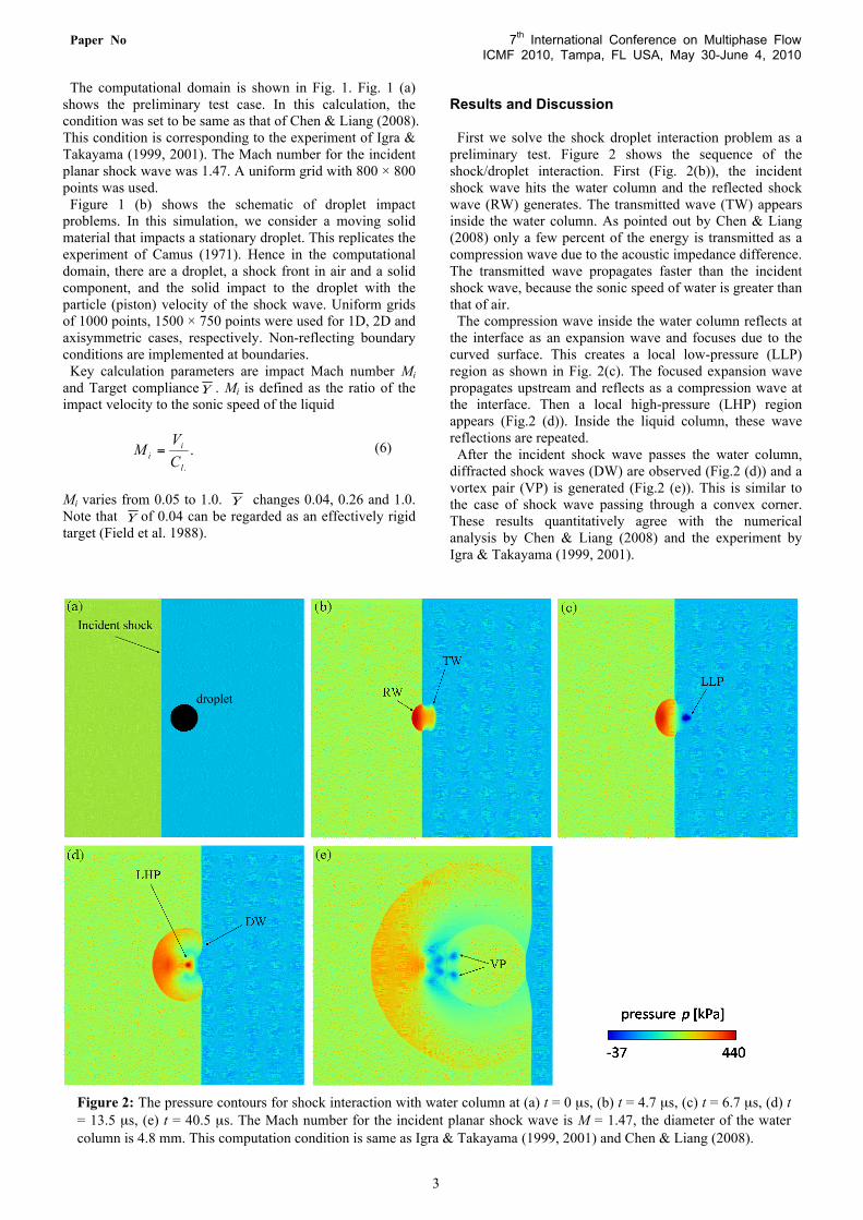
First we solve the shock droplet interaction problem as a preliminary test. Figure 2 shows the sequence of the shock/droplet interaction. First (Fig. 2(b)), the incident shock wave hits the water column and the reflected shock wave (RW) generates. The transmitted wave (TW) appears inside the water column. As pointed out by Chen & Liang (2008) only a few percent of the energy is transmitted as a compression wave due to the acoustic impedance difference. The transmitted wave propagates faster than the incident shock wave, because the sonic speed of water is greater than that of air.
The compression wave inside the water column reflects at the interface as an expansion wave and focuses due to the curved surface. This creates a local low-pressure (LLP) region as shown in Fig. 2(c). The focused expansion wave propagates upstream and reflects as a compression wave at the interface. Then a local high-pressure (LHP) region appears (Fig.2 (d)). Inside the liquid column, these wave reflections are repeated.
After the incident shock wave passes the water column, diffracted shock waves (DW) are observed (Fig.2 (d)) and a vortex pair (VP) is generated (Fig.2 (e)). This is similar to the case of shock wave passing through a convex corner. These results quantitatively agree with the numerical analysis by Chen & Liang (2008) and the experiment by Igra & Takayama (1999, 2001).
Figure 2: The pressure contours for shock interaction with water column at (a) t = 0 µs, (b) t = 4.7 µs, (c) t = 6.7 µs, (d) t = 13.5 µs, (e) t = 40.5 µs. The Mach number for the incident planar shock wave is M = 1.47, the diameter of the water column is 4.8 mm. This computation condition is same as Igra & Takayama (1999, 2001) and Chen & Liang (2008).

Paper No 7th International Conference on Multiphase Flow ICMF 2010, Tampa, FL USA, May 30-June 4, 2010
4
Figure 3: Generated pressure inside water in the 1D problem as a function of Mi and Figure 4: Generated shock speed inside water in the 1D problem.
Next, we discuss the problem of droplet impact on a solid
wall. One-dimensional Riemann problem that may replicate the initial stage of a droplet impact on a solid wall is first considered. Initially both liquid and solid phases are assumed to be in contact, but at the calculation start, the solid wall is set in motion toward the stationary liquid. The generated pressure and shock speed in water are plotted Figs 3 and 4, respectively. We have changed the impact Mach number Mi from 0.05 to 1. Target compliance takes 0.04, 0.26 and 1. The case of = 1 corresponds to the same acoustic impedance, i.e. the case of high speed water impacts water. The pressure is normalized by water hammer pressure Eq. (1). The figure also plots the theoretical estimation by Heymann (1968)
(7)
Here, V is the particle velocity; k is the parameter that takes around 2 for water. This theory assumes that a droplet impacts a rigid target and contains the first-order correction of the shock wave velocity (Haung et al. 1973). The dashed lines show the estimation from Eq. (2).
It follows from Fig. 3 that the generated pressure increases with impact Mach number Mi. For the case of = 0.04, the generated pressure is larger than the water hammer pressure with rigid targets over a wide range of Mi. The difference in the generated pressure caused by the target compliance increases with Mi. For the case of = 1.0, the pressure has only water hammer pressure of rigid target around Mi = 1. At the low Mi, the pressure approaches to the Eq. (2). Figure 4 suggest that the linear theory which assumes the propagation speed of linear waves is invalid in this range of Mi. Figure 5: The density contours for droplet impact with a solid wall. The impact Mach number is 0.2, the target
compliance is 0.04. The labels indicate S: Shock Wave, R: Reflected, F: Focus and J: Jetting.
0 0.2 0.4 0.6 0.8 10.5
1
1.5
2
2.5
3
3.5
Mi
Ms
Y = 0.04Y = 0.26Y = 1.00Heymann(1968)
0 0.2 0.4 0.6 0.8 10
0.5
1
1.5
2
2.5
3
Mi
P /
l ClV i
Y = 0 .04Y = 0 .26Y = 1 .00Heymann(1968)Eq(2)

Paper No 7th International Conference on Multiphase Flow ICMF 2010, Tampa, FL USA, May 30-June 4, 2010
5
Next we discuss two-dimensional and axisymmetric solutions. Figure 5 shows the density counters of time evolution of two-dimensional droplet impact. The impact Mach number Mi is 0.2, the target compliance is 0.04. After the droplet impact, the droplet is deformed and a shock wave (S) is generated (Fig. 5 (b)). The shock wave propagates upward and is followed by a expansion wave that appears along with the free surface (Fig. 5 (c) (d)). This low pressure region appears due to the reflection (R) of the shock wave. This is because the mismatch in acoustic impedance between air and water, and horizontal velocity components of shock wave (Haller et al. 2003). Finally the expansion wave focuses (F) at the top of droplet (Fig. 5 (e)). Also at the bottom of the droplet, side jet formation is observed (Fig. 5 (f)). The results are in qualitative agreement with the experiments (Camus 1971) and numerical analysis (Haller et al. 2002).
As mentioned before, in the initial stage of a droplet impact the non uniform pressure distribution which is greater than the water hammer pressure is generated. The generated pressures of two-dimensional and axisymmetric cases are plotted in Fig. 6 together with one-dimensional results. In the Fig. 6 the droplet center and maximum pressure which occurs at the edge are shown. The detail of the pressure difference at low Mi cases are shown in Fig. 7.
From Figs. 6 and 7, it is found that the generated pressure depends on the droplet impact Mach number Mi. For the high Mi case, the center pressure is almost same as 1D pressure and the edge pressure is about 3 times greater than the center pressure. This tendency reasonably agree with theories of Heymann (1969) and Lesser (1981). They also described that the edge pressure is identical for 2D and 3D, but our results show that the 2D pressure is greater than the 3D pressure.
From Fig. 7 as Mi decreases the edge pressure approaches the center pressure. These pressure are almost identical at the Mi = 0.1. It is also found that the center pressure decreases as the dimension increases and the center pressure of axi-symmetric case is almost half of the 1D pressure in a range of low Mi. This agrees with Engel’s result Eq. (3).
Finally the effect of target compliance on the generated pressure is discussed. Figure 8 shows the time history of the surface pressure with = 0.04 and = 0.26. The impact Mach number Mi is 0.5. This figure clearly shows that the generated pressure decreases as the target becomes more compressible or deformable. Especially the edge pressure is dramatically decreased. Figure 9 shows differences in the target deformation between = 0.04 and = 0.26. This indicates that the wall deformation strongly depends on the target compliance, and the droplet dynamics and the generated pressure can change accordingly as observed in the present computations.
0.1 0.2 0.3 0.4 0.5 0.6 0.7 0.8 0.9 10
1
2
3
4
5
6
7
Mi
P /
l ClV i
1D2D center2D max (edge)axi centeraxi max (edge)
Figure 6: Comparison of generated pressure due to droplet impact.
0.1 0.2 0.3 0.4 0.50
0.5
1
1.5
2
2.5
3
Mi
P /
l ClV i
1D2D center2D max (edge)axi centeraxi max (edge)
Figure 7: Close up figure for Fig.6.
0.3 0.4 0.5 0.6 0.70
0.5
1
1.5
2
2.5
3
t
P /
l ClV i
Pcenter , Y = 0 .04Pmax , Y = 0 .04Pcenter , Y = 0 .26Pmax , Y = 0 .26
Figure 8: Time evolution of generated pressure (Mi = 0.5).

Paper No 7th International Conference on Multiphase Flow ICMF 2010, Tampa, FL USA, May 30-June 4, 2010
6
Figure 9: Target deformation due to the droplet impact (Mi = 0.5). Left and right show the case of of 0.04 and of 0.26, respectively. Conclusions We numerically investigate a high speed droplet impact on
a solid wall. The multicomponent Euler equations with the stiffened equation of state are computed by a FV-WENO scheme with an HLLC Riemann solver that accurately captures shocks and interfaces. In order to compare the available theory and experiments, 1D, 2D and axi-symmetric solutions are obtained. It is found that the generated pressure depends on the droplet impact Mach number Mi. For the low Mi case the pressure differences at the center and the edge are minimized and the pressure is almost half of the 1D case. On the other hand, for the high Mi case the edge pressure is almost 3 times greater than the center pressure. However, increasing the target compliance the edge pressure dramatically decreased. Acknowledgements
This work was conducted during one of the author T. Sanada stayed at California Institute of Technology. T. S. appreciates the support by Murakawa Niro Foundation and Faculty of Engineering, Shizuoka University. References Brunton, J. H. High speed liquid impact. Proc. R. Soc. London. Vol.260, 79-85 (1966) Camus, J. J. A study of high-speed liquid flow in impact and its effect on solid surface. Ph.D. thesis, University of Cambridge, (1971) Chen, H. & Liang, S. M. Flow visualization of shock/water column interactions. Shock Waves, Vol.17, 309-321 (2008) Field, J. E., Lesser, M. B. & Dear J. P. Studies of two-dimension liquid-wedge impact and their relevance to liquid drop impact problems. Proc. R. Soc. London. Vol.401, 225-249 (1985) Field, J. E., Dear, J. P. & Ogren, J. E. The effects of target compliance on liquid drop impact. J. Appl. Phys. Vol.65, 533-540 (1989)
Gottlieb, S. & Shu, C. W. Total variation diminishing Runge-Kutta Schemes. Math. Comp. Vol.67, 73-85, (1998) Haller, K. K., Ventikos, Y., Poulikakos, D. & Monkewitz P. Computational study of high-speed liquid droplet impact. J. Appl. Phys., Vol.92, 2821-2828 (2002) Haller, K. K., Poulikakos, D., Ventikos, Y. & Monkewitz, P. Shock wave formation in droplet impact on a rigid surface: lateral liquid motion and multiple wave structure in the contact line region. J. Fluid Mech. Vol.490, 1-14, (2003) Harlow, F. & Amsden A. Fluid Dynamics. Monograph LA-4700, Los Alamos National Laboratory, (1971) Heymann, F. J. On the shock wave velocity and impact pressure in high-speed liquid-solid impact. J. Basic Engr. Vol.90, 400-402 (1968) Heymann F. J. High-speed impact between liquid drop and solid surface. J. Appl. Phys. Vol.40, 5113-5122 (1969) Huang, Y. C., Hammitt, F. G. & Mitchell, T. M. Note on shock-wave velocity in high-speed liquid-solid impact. J. Appl. Phys. Vol.44, 1868-1869 (1973) Igra, D. & Takayama, K. Investigation of aerodynamic breakup of a cylindrical water droplet. Report of the Institute of Fluid Science, Tohoku University, Vol.11, 123-134 (1999) Igra, D. & Takayama, K. Numerical simulation of shock wave interaction with a water column. Shock Waves, Vol.11, 219-228 (2001) Johnsen, E. & Colonius, T. Numerical simulations of non-spherical bubble collapse. J. Fluid Mech., Vol.629, 231-262 (2009) Johnsen, E. & Colonius, T. Implementation of WENO schemes for compressible multicomponent flow problems. J. Comput. Phys., Vol.219, 715-732 (2006) Lesser, M. B. & Field, J. E. The impact of compressible liquids. Ann. Rev. Fluid Mech., Vol.15, 97-122 (1983) Lesser M. B. Analytic solutions of liquid-drop impact problems. Proc. R. Soc. London, Vol.377, 289-308 (1981) Saurel R. & Abgrall R. A multiphase Godunov method for compressible multifluid and multiphase flows. J. Comput. Phys., Vol.150, 425-467 (1999) Shu, S. W. & Osher, S. Efficient implementation of essentially non-oscillatory shock-capturing scheme. J. Comput. Phys., Vol.77, 439-471 (1988) Tompson, P. A. Compressible-Fluid Dynamics, (1988) Rochester, M. C. & Brunton, J. H. Pressure distribution during drop impact. Proc. 5th Int. Conf. on Erosion by Solid and Liquid Impact, 6-1-6-7 (1979)