numerical analysis of selected materials for …
TRANSCRIPT

A R C H I V E S O F M E T A L L U R G Y A N D M A T E R I A L S
Volume 57 2012 Issue 1
DOI: 10.2478/v10172-012-0008-5
P. FOLĘGA∗ G. SIWIEC∗∗
NUMERICAL ANALYSIS OF SELECTED MATERIALS FOR FLEXSPLINES
ANALIZA NUMERYCZNA WYBRANYCH MATERIAŁÓW KÓŁ PODATNYCH
The computer analysis of the influence of flexspline materials at the strength of the flexspline was performed for two andthree dimensional models using the finite element method and MSC Patran/Nastran software. Calculations were conducted intwo steps. The first one concerns two dimensional models on the contact between the flexspline and the wave generator. Thesecond concerns three dimensional models of flexspline. The application of steel and steel-composite materials as materialof the flexspline in harmonic drive was analysed. In calculations were used two types of composites with an epoxy resin,reinforced by the carbon-fiber or the glass-fiber. The preliminary study of stresses for the developed models was made. Thesteel-composite hybrid flexspline as compared to conventional steel flexspline showed a decrease of maximum stress in theanalyzed dangerous cross-sections. Shapes and the frequency of vibration of the flexsplines were also calculated. The impactof stacking fiber angle on the frequency of vibration in the tested flexsplines is negligible.
Keywords: materials, flexspline, harmonic drive, finite element method
Przeprowadzono analizę komputerową wpływu materiałów kół podatnych na ich wytrzymałość przy pomocy dwu i trój-wymiarowych modeli wykorzystując metodę elementów skończonych oraz oprogramowanie MSC Patran/Nastran. Obliczeniaprzeprowadzono w dwóch etapach. Pierwszy z nich dotyczył dwuwymiarowych modeli kontaktu koła podatnego i gene-ratora fali. Drugi dotyczył trójwymiarowych modeli kół podatnych. Przeprowadzono analizę zastosowania stalowych orazstalowo-kompozytowych materiałów na koła podatne przekładni falowej. W obliczeniach wykorzystano dwa rodzaje kompozy-tów z osnową z żywicy epoksydowej, zbrojonej włóknem węglowym lub włóknem szklanym. Dla opracowanych modeli zostaławykonana wstępna analiza stanu naprężenia. Analizując otrzymane wyniki obliczeń symulacyjnych przyjętych rozwiązań kon-strukcyjnych kół podatnych stwierdzono zmniejszenie wartości naprężeń w rozpatrywanych przekrojach stalowo-kompozytowychkół podatnych w porównaniu z tradycyjnymi kołami stalowymi. Wyznaczono ponadto postacie i częstotliwości drgań badanychkół podatnych. Stwierdzono że, wpływ kąta ułożenia włókien na częstotliwości drgań badanych kół podatnych jest nieznaczny.
1. Introduction
A harmonic drive (Fig. 1) consists of a toothedmechanism, which composed of three main elements:a rigid circular spline, an elliptical wave generator and aflexible spline, which is called the flexspline. The flexs-pline it is the main component of a harmonic drive,which can generate a repeated vibration by the wavegenerator. With this a reason, the flexspline should haveflexibility and good vibration characteristics [2-4].
The wave generator deflects the elastically de-formable flexspline elliptically across the major axis.
Due to that, the teeth of the flexspline engage simul-taneously with the ring gears of circular spline in twozones at either end of the major elliptical axis. Across theminor axis of the elliptically deflected flexspline there isno engagement. When the wave generator rotates, themeshing zones of the flexspline rotate with the gener-ator. A difference in the number of teeth between theflexspline and the circular spline the latter has two teethmore results in a relative movement between these gearwheels. After a complete rotation of the wave generator,the flexspline moves relative to the circular spline by anangle equivalent to two teeth.
∗ SILESIAN UNIVERSITY OF TECHNOLOGY, FACULTY OF TRANSPORT, 40-019 KATOWICE, 8 KRASIŃSKIEGO STR., POLAND∗∗ SILESIAN UNIVERSITY OF TECHNOLOGY, DEPARTMENT OF METALLURGY, 40-019 KATOWICE, 8 KRASIŃSKIEGO STR., POLAND

186
Fig. 1. Main elements of the harmonic drive [1]: 1 – circular spline, 2 – the cup-type of flexspline, 3 – wave generator
Compared to classical toothed gears, harmonicdrives have numerous advantages, but there are somedisadvantages as well. Their main advantages include:high torque capacity, excellent positioning accuracyand repeatability, compact design, zero backlash, highsingle-stage reduction ratios and high torsion stiffness.On the other hand, their drawbacks are: high elastici-ty and nonlinear stiffness and damping. The applicationof toothed harmonic drives in various fields of life ismore and more wide. They are currently used in theautomotive and space industries, in aviation, medicine,automatics and robotics.
When designing the flexspline, it is very importantto determine and choose properly its geometrical fea-tures. Adequate selection of dimensions of the flexs-pline should ensure minimization of stresses in danger-ous cross-sections and a more constant stress distribu-tion along the flexspline, which must be flexible in theradial direction but must be stiff in the torsion direction.These phenomena cannot be avoided when the flexsplineis made of conventional isotropic materials such as steel[1]. Therefore significant enhancement of the harmon-ic drive is possible through a rational selection of geo-metrical parameters of the flexspline, but also throughapplying suitable materials or technological treatments.Using composites on the flexspline enables weight re-duction of the flexspline and increases significantly itsradial susceptibility and damping of vibration [2, 5-6].The production of flexsplines made entirely from com-posites is, however, constrained by technological difficul-ties connected with creating their toothed ring gear. Thisproblem may be solved by the application of so-called„complex” steel-composite hybrid flexsplines [7]. An ad-vantage of this solution is the possibility of producing asteel flexspline with toothed ring gear, where a compositeis applied onto the internal surface of a steel flexspline(most often, throughout the width of the toothed ringgear – Fig. 2). That may significantly improve its me-chanical properties in this area, because the composite
material has a high specific strength, a high stiffnessand a high damping capacity [2, 5]. An example of suchsolution and a description of the technological processof producing such flexspline are presented in work [3].
Fig. 2. Construction of a steel-composite cup-type flexspline
2. Numerical models of flexsplines
Creating parametric models of flexspline we mustspecify boundary conditions. This involves the problemof determining the load distribution in toothed ring gearof the flexspline and in contact zone the wave genera-tor with the flexspline, depending on the torque. In hisexperiments Ivanov [8] observed that under the load-ing the flexspline tends to detach itself from the wavegenerator in two regions at some angle after the majordeformation axis due to circumferential buckling underthe loading. The approximate loading conditions of theflexspline and the analytical procedure for determinationof the stress-deformation state of the flexspline is basedon the modified theory of shells, described by Ivanov [8].The analytical procedures assume that under the loadingdifferent regions of the flexspline deform in the shapeof known geometrically curves, which are mathemati-cally easy to describe. Such simplification gives raise

187
to a discontinuous stress field along the circumferenceof the flexspline and overestimation of the peak stressvalue used for the design of flexspline thickness. There-fore a numerical analysis of the flexspline becomes anecessity for optimum design. Recently few researchershave successfully used the FEM to analyze the flexs-pline. Suvalov and Gorelov [9-10] conducted series of2D FEM calculations of the flexspline cross-section inthe region of two loaded teeth. Toropcjin [11] chose theaxial cross-section for its 2D FEM calculations aiming atthe optimum design of the flexspline, which is fixed onone end to the housing. However, this analysis failed toaddress the problem, because the flexspline is the buck-ling by the torque [4, 9-12]. Kayabasi and Erzincanli [12]studied the stresses on flexspline teeth and find optimumshape of teeth to maximize fatigue life.
In this paper, the authors proposed a numericalanalysis of the flexspline divided into two stages. Thefirst most important step involves a nonlinear finite ele-ment analysis of the contact between the flexspline andthe wave generator [13-14]. The radial cross-section ofthe flexspline is analyzed in respect to the maximumdisplacements caused by the wave generator. Since theloading of the flexspline is not symmetrical the wholeflexspline is divided into elements (Fig. 3).
Fig. 3. The two-dimensional FEM model
The wave generator construction used in the modelis opposite positioned discs. The contact between theflexspline and each of the discs is along the angle ± 30◦
measured from the major symmetrical axis. The wavegenerators discs were modeled with a single line of finiteelements along the discs boundaries in range ±90◦ fromthe major symmetrical axis. Inner nodes of the flexsplinemesh and the outer nodes of the discs meshes were incontact along the angle ±30◦, measured from the major
Fig. 4. Chart of radial (w) and tangential (v) displacements as a function of angle measured from the large axis of the wave generator
188
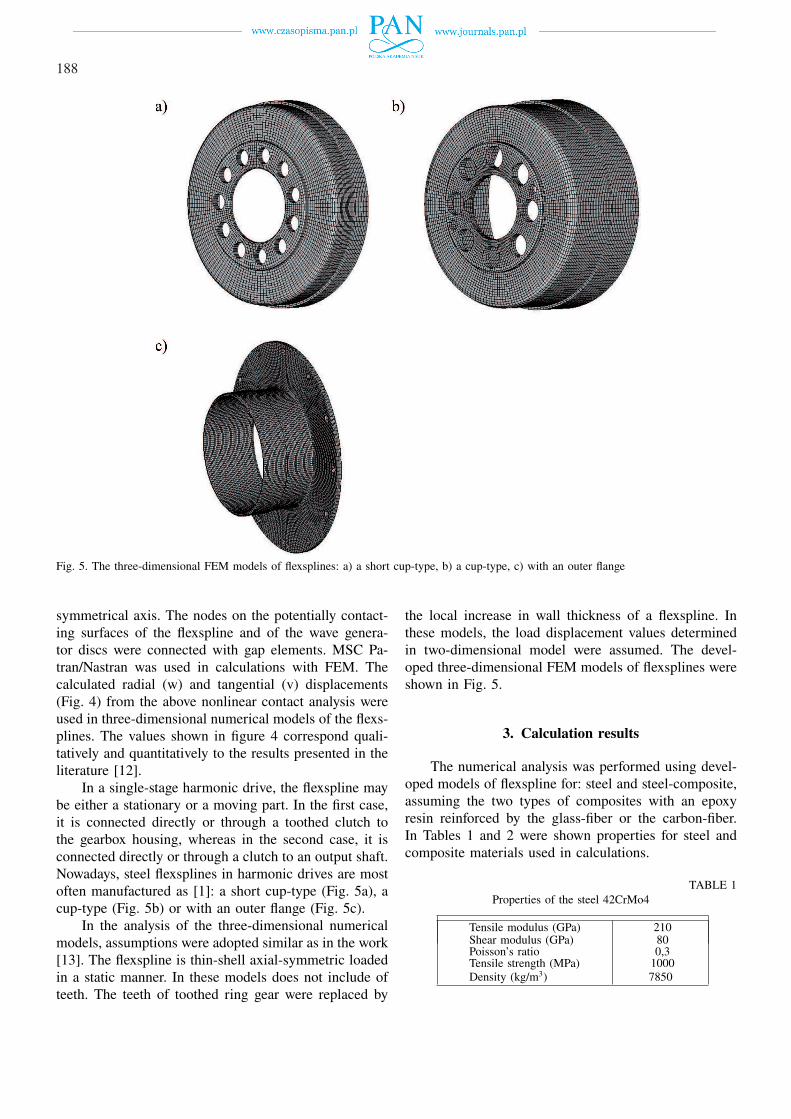
Fig. 5. The three-dimensional FEM models of flexsplines: a) a short cup-type, b) a cup-type, c) with an outer flange
symmetrical axis. The nodes on the potentially contact-ing surfaces of the flexspline and of the wave genera-tor discs were connected with gap elements. MSC Pa-tran/Nastran was used in calculations with FEM. Thecalculated radial (w) and tangential (v) displacements(Fig. 4) from the above nonlinear contact analysis wereused in three-dimensional numerical models of the flexs-plines. The values shown in figure 4 correspond quali-tatively and quantitatively to the results presented in theliterature [12].
In a single-stage harmonic drive, the flexspline maybe either a stationary or a moving part. In the first case,it is connected directly or through a toothed clutch tothe gearbox housing, whereas in the second case, it isconnected directly or through a clutch to an output shaft.Nowadays, steel flexsplines in harmonic drives are mostoften manufactured as [1]: a short cup-type (Fig. 5a), acup-type (Fig. 5b) or with an outer flange (Fig. 5c).
In the analysis of the three-dimensional numericalmodels, assumptions were adopted similar as in the work[13]. The flexspline is thin-shell axial-symmetric loadedin a static manner. In these models does not include ofteeth. The teeth of toothed ring gear were replaced by
the local increase in wall thickness of a flexspline. Inthese models, the load displacement values determinedin two-dimensional model were assumed. The devel-oped three-dimensional FEM models of flexsplines wereshown in Fig. 5.
3. Calculation results
The numerical analysis was performed using devel-oped models of flexspline for: steel and steel-composite,assuming the two types of composites with an epoxyresin reinforced by the glass-fiber or the carbon-fiber.In Tables 1 and 2 were shown properties for steel andcomposite materials used in calculations.
TABLE 1Properties of the steel 42CrMo4
Tensile modulus (GPa)Shear modulus (GPa)Poisson’s ratioTensile strength (MPa)Density (kg/m3)
210800,3
10007850

189
TABLE 2Properties of the composite materials
Properties of the epoxy resinTensile modulus (GPa)Shear modulus (GPa)Poisson’s ratioTensile strength (MPa)Shear strength (MPa)Density (kg/m3)
1,30,450,4045
29,51200
Properties of the fiber Glass fiber Carbon fiberEL (GPa)ET (GPa)GLT (GPa)νLTDensity (kg/m3)
43,55,05,00,252050
1308,06,00,281710
Fig. 6. The geometrical dimensions of flexsplines: a) a cup-type,b) with an outer flange
The geometrical dimensions of flexsplines adoptedfor the calculation were shown in Figure 6 and Table 3.In calculations thickness of the composite of gK = 0,6mm on width bW = 25 mm were assumed. Compositematerials used in calculations were analyzed for differentvalues of the stacking fiber angle θ (fiber orientation) inthe outer and inner layer, in values to, respectively, ±150,±300, ±450, ±600, and ±750.
TABLE 3The geometrical dimensions of flexsplines
L [mm] 51
dw [mm] 107
dd [mm] (a cup type of flexspline) 25
dd [mm] (a flexspline with outer flange) 140
bw [mm] 25
gk [mm] 0,6
The analysis of the stress state was performed for thefollowing cross-sections of the investigated flexsplines(Fig. 6): in the middle of the width of the toothed ringgear (A-A), on the boundary of transition of the toothedring gear into a smooth part of the flexspline (B-B), inthe middle of the flexspline length (C-C) and in the backpart of the flexspline (D-D). Dangerous sections exposedto a considerable increase of stress values are located onthe boundary of transition of the toothed ring gear intoa smooth and in the back part of the flexspline (sectionsB-B and D-D, respectively).
Examples of the results of calculations conduct-ed on the prepared numerical models of the steel andsteel-composite hybrid flexsplines are presented in Figs.7 to 10. The calculations have shown a decrease inthe maximum stress in the studied sections in thesteel-composite hybrid flexsplines in comparison to thetraditional steel flexspline (Fig. 7). Figure 8 shows the re-sults concerning the impact of the stacking fiber angle onthe stresses in cross-section (B-B). For steel-compositehybrid flexsplines with an epoxy resin reinforced by thecarbon-fiber, a reduction of stress was found in compar-ison to steel flexspline for stacking fiber angle θ = ±750
(up to 9%). For steel-composite hybrid flexsplines withan epoxy resin reinforced by the glass-fiber the reductionof stress is observed at the level of 2% in relation to thesteel flexsplines.

190
Fig. 7. Maximum stress in the studied sections of a cup-type flexs-pline
For the studied numerical models of flexsplines, theshapes and values of vibration frequency were also de-termined. Fig. 9 shows some examples of the shapesof vibration for the steel flexspline. Fig. 10 shows thevalues of the first frequency for the analysed flexsplinesdepending on the stacking fiber angle. When analyzingthe results of calculations shown in Fig. 10 it could beseen that the impact of stacking fiber angle for the testedflexsplines on the frequency of vibration is negligible.Using the steel-composite hybrid flexsplines made withan epoxy resin reinforced by the carbon-fiber resultedin more than 2.0 fold increase in the value of the firstnatural frequencies compared with the steel flexsplines,whose first vibration frequency was 750 Hz in a cup-typeand 610 Hz with an outer flange.
Fig. 8. Stresses of analyzed flexsplines in section (B-B) dependingon stacking fiber angle: a) a cup-type, b) with an outer flange
Fig. 9. Shape of the steel flexspline: a) first, b) fourth, c) fifth, d) sixth

191
Fig. 10. The first natural frequency of the steel-composite hybrid flexsplines depending on stacking fiber angle: a) a cup-type, b) with anouter flange
4. Summary
Using the finite element method a numerical analy-sis was performed for the steel and steel-compositehybrid flexsplines. The calculations have shown a re-duction of maximum stresses in the analysed sectionsfor the steel-composite hybrid flexsplines in compari-son to the traditional steel flexsplines. The biggest de-crease of stress values occurs when an epoxy resin re-inforced by the carbon-fiber for the stacking fiber an-gle θ = ±750 were used. When analysing the calcu-lation results regarding proper vibration, it was foundthat the steel-composite hybrid flexsplines increases thevalue of vibration frequency in comparison with thesteel flexsplines. Influence of the stacking fiber angleon the frequency of vibration for the tested flexsplinesis negligible. The next stage of the research will consistof constructing a prototype of harmonic drive with asteel-composite flexspline and carrying out experimentaltests.
REFERENCES
[1] General Catalogue Harmonic Drive AG, 05.2009.[2] K.S. J e o n g, D.G. L e e, Development of the compos-
ite flexspline for a cycloid-type harmonic drive using netshape manufacturing method, Composite Structures 32,557-565 (1995).
[3] S.H. O h, S.H. C h a n g, Improvement of the dynamicproperties of a steel-composite hybrid flexspline of a har-monic drive, Composite Structures 38, 251-260 (1997).
[4] H.S. J e o n, S.H. O h, S.H. C h a n g, A study on stressand vibration analysis of a steel and hybrid flexspline
for harmonic drive, Composite Structures, 47, 827-833(1999).
[5] K. B o r y s o v s k a, D. V e r b y l o, Yu. P o -d r e z o v, M. S z a f r a n, The structural optimizationof ceramic-organic composites, Archives of Metallurgyand Materials, 54, 4, 875-879 (2009).
[6] M. H e b d a, R.B. P ę c h e r s k i, Energy-based crite-rion of elastic limit states in fibre-reinforced composites,Archives of Metallurgy and Materials, 50, 4, 1073-1088(2005).
[7] P. F o l ę g a, R. B u r d z i k, T. W ę g r z y n, A.P.S i l v a, Using new materials for flexsplines of harmonicdrive, Engineering’ 2009 – Innovation and development,5th Engineering Conference, Covilha – Portugal (2009).
[8] M.N. I v a n o v, Harmonic gear drive, Moscow (1981).[9] W.N. G o r e l o w, Stress state of the teethed ring of har-
monic drives flexible gear, Soviet Engineering Research5, 7-10 (1979).
[10] S.A. S u v a l o v, V.N. G o r e l o v, Stress in the flex-ible gear by finite element method, Soviet EngineeringResearch 3, 9-11 (1983).
[11] V.A. T o r o p i c j i n, Stress-deformation analysis of theflexible gear of harmonic drive by finite element method,Soviet Engineering Research 2, 17-18 (1988).
[12] O. K a y a b a s i, F. E r z i n c a n l i, Shape optimiza-tion of tooth profile of a flexspline for a harmonic driveby finite element modelling, Materials and Design 28,441-447 (2005).
[13] P. F o l ę g a, A. W i l k, Dobór cech konstrukcyjnychtulei podatnej przekładni falowej z wykorzystaniemMES, Przegląd Mechaniczny 10, 31-36 (2002).
[14] P. F o l ę g a, A. W i l k, Analiza numeryczna tuleipodatnej z wykorzystaniem elementów kontaktowychMES, ZN Pol. Śl., ser. Transport 41, 35-42 (2000).
Received: 10 April 2011.