numerical evaluation on shell buckling of empty thin-walled … · tanks under wind load according...
TRANSCRIPT
Numerical evaluation on shell buckling of empty thin-walled steeltanks under wind load according to current American and Europeandesign codes
Chrysanthos Maraveas a,b, Georgios A. Balokas b,c, Konstantinos Daniel Tsavdaridis d
a School of Mechanical, Aerospace and Civil Engineering, University of Manchester, UKb C.Maraveas Partnership – Consulting Engineers, Athens, Greecec Department of Mechanics, National Technical University of Athens, Greeced Institute for Resilient Infrastructure, School of Civil Engineering, University of Leeds, UK
a r t i c l e i n f o
Article history:
Received 14 May 2015
Received in revised form
4 July 2015
Accepted 6 July 2015
Keywords:
Steel tanks
Shell buckling
Finite element modeling
Nonlinear analysis
Wind load
a b s t r a c t
Liquid storage steel tanks are vertical above-ground cylindrical shells and as typical thin-walled struc-
tures, they are very sensitive to buckling under wind loads, especially when they are empty or at low
liquid level. Previous studies revealed discrepancies in buckling resistance of empty tanks between the
design method proposed by the American Standard API 650 and the analytical formulas recommended
by the European Standard EN1993-1-6 and EN1993-4-2. This study presents a comparison between the
provisions of current design codes by performing all types of numerical buckling analyses recommended
by Eurocodes (i.e. LBA-linear elastic bifurcation analysis, GNA-geometrically nonlinear elastic analysis of
the perfect tank and GNIA-geometrically nonlinear elastic analysis of the imperfect tank). Such analyses
are performed in order to evaluate the buckling resistance of two existing thin-walled steel tanks, with
large diameters and variable wall thickness. In addition, a discussion is unfolded about the differences
between computational and analytical methods and the conservatism that the latter method imposes. An
influence study on the geometric imperfections and the boundary conditions is also conducted. In-
vestigation on the boundary conditions at the foot of the tank highlights the sensitivity to the fixation of
the vertical translational degree of freedom. Further, it is indicated that the imperfection magnitude
recommended by the EN1993-1-6 is extremely unfavorable when applied to large diameter tanks.
Comments and conclusions achieved could be helpful in order to evaluate the safety of the current
design codes and shed more light towards the most accurate one.
& 2015 Elsevier Ltd. All rights reserved.
1. Introduction
Above-ground, vertical tanks of cylindrical shape are con-
structed in industrial and agricultural plants to store various fluids
such as petroleum, oil, fuel etc. They are welded, thin-walled
structures with large diameters, and hence buckling may occur
when they are subjected to wind loads at their empty or partially
filled state. Failure of such tanks results, in most cases, in a tre-
mendous loss of financial and human resources, as well as com-
poses a threat to public safety and an environmental hazard.
Studies concerning wind-induced buckling of steel tanks have
been increasing over the past few decades, since structural stabi-
lity becomes critical for response and a major concern for the
designer.
Early studies approached this matter based on analytical for-
mulations of energy theory and tried to verify results with ex-
periments [1]. Following, numerical approaches have been con-
ducted extensively, inserting the imperfection sensitivity
parameter [2,3]. Different tank variations have been investigated,
like open-topped [4] and fixed-roof [5–7], combining computa-
tional methods and experimental results. Jaca and Godoy [8] in-
dicated that buckling of tanks sometimes can occur under mod-
erate wind load during their construction. Another subject of in-
terest is the wind buckling behavior of grouped, arranged tanks
[9–11]. The simulation of wind load distribution acting on the tank
shell is an open research field [12–14]. Innovative ways of
strengthening and improving buckling capacity have been pro-
posed [15]. Sosa and Godoy [16] and Burgos et al. [17] have re-
cently taken a turn towards analytical methods, in order to im-
prove buckling evaluation by proposing new methodologies.
This study aims to appraise the efficiency of current design
specifications in addressing structural stability of empty, large
tanks when subjected to wind actions. Most recent codes
(EN1993-1-6 and EN1993-4-2) have not yet seen many field ap-
plications and their results may raise doubts. This paper offers a
comparison between API 650 and the Eurocodes, by performing
Contents lists available at ScienceDirect
journal homepage: www.elsevier.com/locate/tws
Thin-Walled Structures
http://dx.doi.org/10.1016/j.tws.2015.07.007
0263-8231/& 2015 Elsevier Ltd. All rights reserved.
Thin-Walled Structures 95 (2015) 152–160

three types of buckling analysis recommended by the EN1993-1-6
for numerical investigation and relating the results with previous
studies [18] conducted with analytical methods (closed-form, ex-
plicit expressions) proposed by the aforementioned codes. Thus,
the stability of two existing large-diameter, steel tanks at empty
state is evaluated.
The study is organized as follows: Section 2 describes the de-
sign philosophy of API 650 [19] and EN1993-1-6. In Section 3 the
geometry of the two existing tanks is presented in detail and
Section 4, presents the finite element models used for analyses
and the wind pressures simulated for each code. Section 5 de-
scribes the linear bifurcation analysis (LBA) and in Sections 6 and 7
geometrically nonlinear buckling behavior is investigated for
perfect (GNA) and imperfect (GNIA) models respectively. In Sec-
tion 8 comparison results are discussed and finally in Section 9,
some helpful conclusions are reached.
2. Description of current code provisions
The most commonly used standards for assessing the structural
stability of thin-walled structures are the API 650 and EN1993-1-6.
The American Standard API 650 provides two empirical methods
(the one-foot method and the variable design point method) for
selecting the thickness of each shell course, depending on the
geometry of the tank, the operational liquid level, the material
used, the density of the contained fluid and the allowance for
corrosion. The aforementioned methods are based on the concept
of limiting the tensile stresses of the shell due to hydrostatic
pressure while they do not consider for buckling. The buckling
limit state is considered only indirectly, via an empirical design
method that mandates stiffening of the shell (with circumferential
girders at specific heights) depending on the thickness, height and
wind velocity. The lack of mathematical formulation for evaluating
the shell stability poses a major disadvantage.
On the contrary, the European standard EN1993-1-6 [20] con-
tains the theoretical background and provides the state-of-the-art
methodologies for evaluating explicitly the buckling resistance of
shell structures. Provisions include analytical expressions for cal-
culating the buckling capacity in terms of stresses and also pro-
pose several numerical methods, like linear bifurcation analysis for
obtaining the critical elastic buckling load as well as analyses that
include geometrical and material nonlinearities and imperfections.
Even though its provisions are limited to axisymmetric geome-
tries, the European Standard has a wide range of applications with
regard to cylindrical tanks. It is of paramount importance that the
code quantifies the buckling resistance in terms of critical stresses
or critical loads. An analytical procedure for evaluating the buck-
ling resistance of shells with variable wall thickness has also been
developed. Most of the approaches recommended by the Eur-
opean Standard require the use of computational methods, such as
the finite element method, for analyzing the shell. The use of
simplified expressions, according to basic principles of mechanics,
for determining the design stresses is permitted only in certain
cases. However, it should be highlighted that the European Stan-
dard is still very recent, and its applicability to the field con-
struction has not been adequately confirmed up to date.
3. Geometry of the tanks
The two existing, thin-walled and large diameter steel tanks
under investigation (T-776 and T-761) are shown in Fig. 1. They are
located at the refinery of Motor Oil Hellas S.A. (Korinthos, Greece).
Both tanks are cylindrical, self-supported (not anchored to the
foundation), with flat bottoms and are considered empty. Tank
T-776 supports a conical roof with a slope equal to 1/6, while the
other tank is open-topped. The conical roof is supported by a truss
structure with three groups of sections (L125x75�8, HEM1000
and SHS_80x80�8). The geometrical data of both tanks, including
distinct locations of the ring stiffeners (wind girders) along the
circumference, are presented in Table 1. It can be seen that the
aspect ratio of tanks (H/D) is quite low (0.43 for T-776 and 0.22 for
T-761).
Both tanks have variable wall thicknesses and their cylindrical
shell is divided in nine courses. The width and thickness of each
shell course along with relevant information regarding the bottom
and roof (where applicable) are summarized in Table 2. The choice
for the particular representative case studies is based on the
variability of the geometric characteristics (aspect ratio, stiffeners,
roof tops etc.) covering different structural behaviours observed in
Fig. 1. On-site pictures of tank T-776 (i) and tank T-761 (ii).
Table 1
Geometrical characteristics of tanks T-776 and T-761.
Tank ID Shell
Height
(m)
Roof
Height
(m)
Inside Dia-
meter (m)
1st Wind
Girder
Height* (m)
2nd Wind
Girder
Height* (m)
T-776 20.032 3.911 46.939 14.860 -
T-761 19.500 - 88.430 15.350 18.400
* Wind girder height is measured from the bottom of the tank.
C. Maraveas et al. / Thin-Walled Structures 95 (2015) 152–160 153

a considerable range of applications for storage tanks found in
practice.
4. Computational models
A separate 3D finite element (FE) model was created for each
tank. The commercial FE package ABAQUS [21] was used to si-
mulate the tanks with geometric and material properties similar to
the existing structures and to perform the required analyses. The
S8R5 element type was used for the cylindrical shell and the
bottom of each tank (but also for the roof shell for tank T-776). It is
a rectangular, doubly curved, thin, continuum shell element with
reduced integration and 8 nodes. Each node has 5 degrees of
freedom: translations in each spatial coordinate and two rotations
with respect to the in-plane axis. Such characteristics satisfy the
modeling requirements of EN1993-1-6 [20]. The remaining struc-
tural parts (wind girders, top curb angles, roof trusses etc.) were
simulated using beam elements. Element B31 was used, which is a
3D Timoshenko beam element with linear interpolation, which
allows for transverse shear deformation and is suitable for thick as
well as slender beams. Discretization was selected to account for
shell thickness gradual change and the location of stiffeners. Re-
garding the boundary conditions at the bottom, the most common
assumption in similar studies is the fully fixed state. In this study
tanks are simply supported (unanchored) so linear elastic, com-
pression-only, translational springs were used to model the
foundation of the tanks at the vertical (meridional) direction, in
order to allow the wind-induced uplift of the tank. The constants
for the support springs were determined from the soil factor. A
direct comparison is made between the two assumptions for the
boundary conditions (fully fixed and compression-only vertical
springs) for all analyses performed. In all computational models,
the material was modeled as elastic and isotropic for all structural
members, with the modulus of elasticity equal to E¼2.1�105
N/mm2 and Poisson’s ratio equal to ν¼0.3. The FE models of both
tanks are presented in Fig. 2.
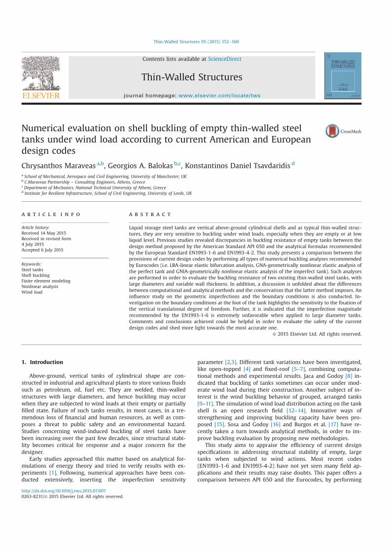
The wind load is simulated as pressure distribution acting on
the circumferential shell. According to current code provisions for
cylindrical shell structures, this pressure varies along both height
and circumference of the shell. The height variation is not sig-
nificant for tanks [20], hence the pressure is assumed to be con-
stant along the height, as opposed to silos. It has been experi-
mentally observed how cosine families can represent circumfer-
ential pressures on shells, so most of the formulations established
to define circumferential patterns of pressure employ Fourier co-
sine series. Wind pressure can generally be defined as:
q c q 1w p= ¯ ( )
Where cp is the wind pressure coefficient and q̄ is the pressure
value at a specific height, on the incidence of the wind (wind-
ward). Wind pressure coefficient is specified using Fourier series
decomposition:
c a icos2
p
i
m
i
0
∑θ θ( ) = ( )( )=
Where θ is the angle measured from the windward direction
(θ¼0° for windward and θ¼180° for leeward) and ai is the Fourier
coefficients. Several proposals have been made for these coeffi-
cients [13]. EN1991-1-4 [22] includes formulations for calculating
specific values of the distribution based on various parameters, but
does not provide the Fourier coefficients used for obtaining these
formulations. This study followed the proposal of Greiner [23] as it
seems to more accurately approximate the shape of the EN1991-1-
4 pressure distribution, using the expression:
c 0.55 0.25 cos 1 cos 2 0.45 cos 3
0.15 cos 4 3
p θ θ θ θ
θ
( ) = − + ( ) + ( ) + ( )
+ ( ) ( )
EN1993-4-2 [24] allows wind simulation through an equivalent
uniform pressure throughout the circumference of the tank, when
several requirements are fulfilled. API 650 assumes uniform wind
Table 2
Shell courses details for tanks T-776 and T-761.
Course No.* Course Thickness (mm) Course Width (mm)
T-776 T-761 T-776 T-761
1 22.25 38.60 2438 2222
2 18.93 37.18 2438 2222
3 16.24 28.20 2438 2222
4 13.57 24.59 2438 2222
5 10.9 19.96 2438 2222
6 8.22 15.60 1940 2222
7 8.00 11.20 1940 2222
8 8.00 9.50 1940 2222
9-top 8.00 9.50 1940 1724
Bottom Shells 6.40 6.40 2102 Variable
Roof Shells 5.00 - 1502 -
* Courses are numbered from bottom to top (i.e. No1 refers to the bottom shell
course etc.).
Fig. 2. Simulation of T-776 (i) and T-761 (ii) with the FEM.
C. Maraveas et al. / Thin-Walled Structures 95 (2015) 152–160154
loading on any occasion. This assumption is investigated numeri-
cally and the results for both pressure distribution proposals are
compared. Fig. 3 demonstrates a representative schematic dis-
tribution of wind pressure based on the above formulations, as
well as the uniform wind pressure.
5. Linear bifurcation analysis (LBA)
EN1993-1-6 recommends linear elastic bifurcation (eigenvalue)
analysis as a method which evaluates the linear bifurcation ei-
genvalue for a thin-walled shell structure on the basis of the small
deflection linear elastic shell bending theory, related to the perfect
geometry of the middle surface of the shell. It is a linear pertur-
bation procedure that can be the first step in a buckling analysis,
providing a preliminary evaluation of buckling behavior. It obtains
the lowest eigenvalue at which the shell may buckle into a dif-
ferent deformation mode, assuming however no change of geo-
metry, no change in the direction of action of the loads and no
material degradation. Imperfections of all kind are ignored, but
buckling mode results can be introduced as an initial geometric
imperfection in the non-linear analysis.
The bifurcation buckling analysis for both tanks under wind
load is presented herein. Wind pressure distribution, as proposed
by EN1993-1-6, is applied and uniform pressure adopted by API
650 is investigated for comparison. Results concerning dis-
crepancies between fully fixed boundary conditions and com-
pression-only translational elastic springs are also provided. The
buckling capacity is calculated through buckling load factors (λ)
that multiply the reference wind pressure such that λc is a critical
load of the tank, for a wind profile that is assumed constant during
the load process. Reference pressures for both EN1993-1-6 and
uniform distributions were set up to 1 kPa so that λc would di-
rectly represent the critical load. Results for critical buckling wind
loads are summarized in Table 3. Buckling deformation modes
corresponding to the critical load factors are presented in Fig. 4
and Fig. 5, for tank T-776 and tank T-761 respectively. It is ob-
served that buckling occurs at the windward regionwhen EN1993-
1-6 wind pressure distribution is applied, with a slightly greater
critical load than uniform pressure for T-761. As Zhao and Lin [4]
recommended, it might be acceptable for the structural designer
to neglect the negative wind pressures, as the windward positive
pressure govern the buckling capacity. At final, buckling initiated
at the thinner shell courses for both tanks. The buckling mode of
tank T-761 (Fig. 5) is located below both wind girders, as they are
set at a small distance and offer great stiffness to the upper thin
shell courses. It is also noted that fully fixed boundary conditions
(only concerns EN19993-1-6 wind pressure) might overestimate
buckling capacity for T-761.
6. Geometrically nonlinear analysis (GNA)
In order to obtain a more accurate buckling behavior, EN1993-
1-6 proposes a geometrically nonlinear analysis. This is based on
the principles of shell bending theory applied to the perfect
structure, including the nonlinear large deflection theory for the
displacements which accounts for any change in geometry due to
the actions on the shell. The nonlinear analysis satisfies both
equilibrium and compatibility of the deflections under conditions
in which the change in the geometry of the structure caused by
loading is included. The resulting field of stresses matches the
definition of primary plus secondary stresses. This study did not
account for material nonlinearity, since stresses acting on the shell
of such thin walled structures are low while the buckling occurs
before the material yielding. ABAQUS software uses the incre-
mental and iterative Newton-Raphson method to obtain solutions
for nonlinear problems, by applying the specified loads gradually
and incrementally working towards the final solution. Riks algo-
rithm was chosen for the different variations of Newton-Raphson
method, which is an arc-length technique that can provide solu-
tions even in cases of complex, unstable responses of the structure
investigated [21].
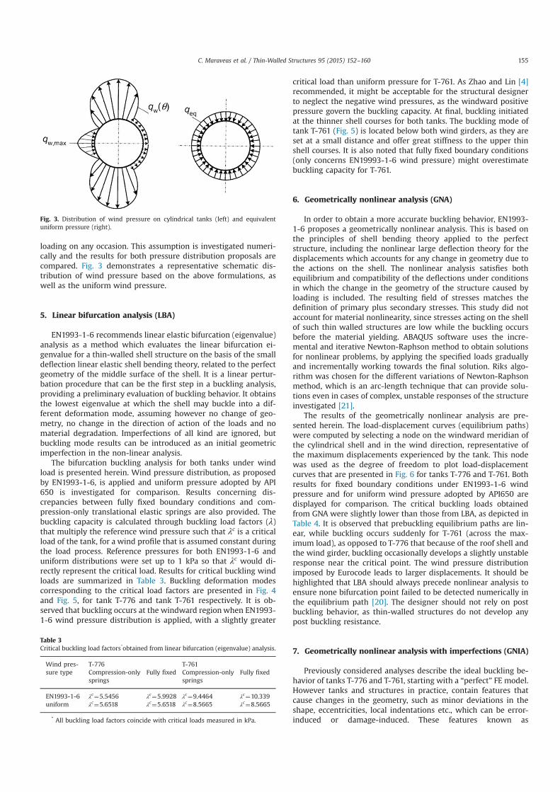
The results of the geometrically nonlinear analysis are pre-
sented herein. The load-displacement curves (equilibrium paths)
were computed by selecting a node on the windward meridian of
the cylindrical shell and in the wind direction, representative of
the maximum displacements experienced by the tank. This node
was used as the degree of freedom to plot load-displacement
curves that are presented in Fig. 6 for tanks T-776 and T-761. Both
results for fixed boundary conditions under EN1993-1-6 wind
pressure and for uniform wind pressure adopted by API650 are
displayed for comparison. The critical buckling loads obtained
from GNA were slightly lower than those from LBA, as depicted in
Table 4. It is observed that prebuckling equilibrium paths are lin-
ear, while buckling occurs suddenly for T-761 (across the max-
imum load), as opposed to T-776 that because of the roof shell and
the wind girder, buckling occasionally develops a slightly unstable
response near the critical point. The wind pressure distribution
imposed by Eurocode leads to larger displacements. It should be
highlighted that LBA should always precede nonlinear analysis to
ensure none bifurcation point failed to be detected numerically in
the equilibrium path [20]. The designer should not rely on post
buckling behavior, as thin-walled structures do not develop any
post buckling resistance.
7. Geometrically nonlinear analysis with imperfections (GNIA)
Previously considered analyses describe the ideal buckling be-
havior of tanks T-776 and T-761, starting with a “perfect” FE model.
However tanks and structures in practice, contain features that
cause changes in the geometry, such as minor deviations in the
shape, eccentricities, local indentations etc., which can be error-
induced or damage-induced. These features known as
Fig. 3. Distribution of wind pressure on cylindrical tanks (left) and equivalent
uniform pressure (right).
Table 3
Critical buckling load factors*obtained from linear bifurcation (eigenvalue) analysis.
Wind pres-
sure type
T-776 T-761
Compression-only
springs
Fully fixed Compression-only
springs
Fully fixed
EN1993-1-6 λc¼5.5456 λ
c¼5.9928 λ
c¼9.4464 λ
c¼10.339
uniform λc¼5.6518 λ
c¼5.6518 λ
c¼8.5665 λ
c¼8.5665
* All buckling load factors coincide with critical loads measured in kPa.
C. Maraveas et al. / Thin-Walled Structures 95 (2015) 152–160 155

imperfections can alter the buckling behavior radically and should
always be considered in the design process.
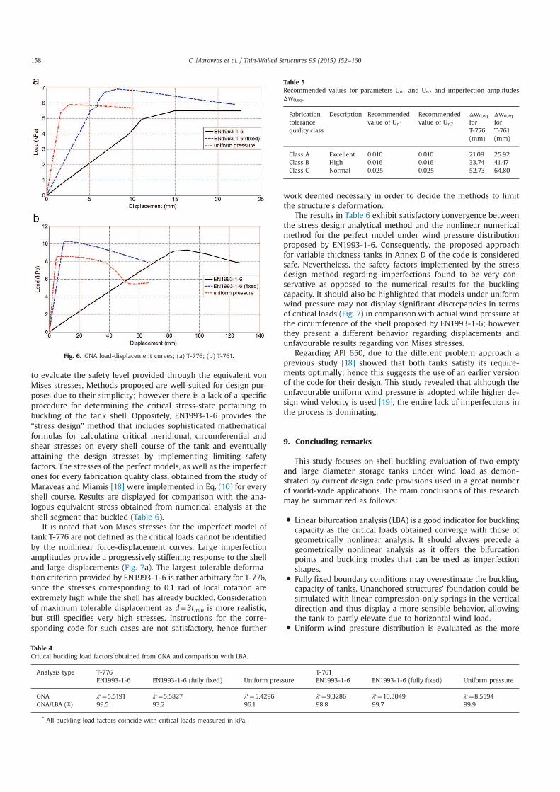
In order to estimate the magnitude of geometrical imperfec-
tions, EN1993-1-6 [20] defines three fabrication tolerance quality
classes (Class A: excellent, Class B: high and Class C: normal fab-
rication). Class selection is based on representative sample mea-
surements conducted on the unloaded and completed structure. A
clear distinction, based on the imperfection type being considered,
is made from fabrication quality tolerance measurements. More
specifically they are categorized as: a) out-of-roundness mea-
surements, which are associated with the internal diameter of the
shell, b) non-intended eccentricity measurements at the joints of
the connected plates, c) dimple measurements, in the meridional
direction and along the circumference of the shell, including
measurements across the welds and d) flatness measurements at
the interface of the shell and its bottom. The fabrication quality
class is assessed separately for each measurement type, according
to the tolerances specified in EN1993-1-6 [20]. The lowest quality
class is then assigned to the shell structure.
It is clear that when the imperfection cannot be measured or
otherwise be made known (e.g. the structure has not been build
and the contractor does not have accurate tolerance data), the
imperfect shape with the most unfavorable effect should be as-
sumed and applied to the perfect model geometry. The eigen-
mode-affine pattern should be used unless a different unfavorable
pattern can be justified [20]. The amplitude of the adopted
equivalent geometric imperfection form should be taken as
dependent on the fabrication tolerance quality class. The max-
imum deviation of the geometry of the equivalent imperfection
from the perfect shape should be given by the above expression:
w w wmax ; 4eq eq eq0, 0, ,1 0, ,2{ }Δ Δ Δ= ( )
Where:
w l U 5eq g n0, ,1 1Δ = ( )
w n tU 6eq i n0, ,2 2Δ = ( )
Where lg is the corresponding gauge length, t is the local shell wall
thickness, ni is a multiplier to achieve an appropriate tolerance
level (recommended value: 25) and Un1, Un2 are the dimple im-
perfection amplitude parameters for the corresponding fabrication
tolerance quality class. Recommended values for Un1 and Un2 are
given in Table 5. The gauge length parameter included in Eq. (5)
should be taken for both the meridional and the circumferential
directions as the maximum of the following:
l rt4 7gx = ( )
l l rt l r2.3 , but 8g g2
0.5( )= ≤ ( )θθ
l t l mm25 , but 500 9g gw w= ≤ ( )
Where r is the radius of the middle surface normal to the axis of
Fig. 4. Buckling deformation modes for tank T-776; (a) Wind pressure distribution according to EN1993-1-6; (b) Uniform wind pressure distribution.
C. Maraveas et al. / Thin-Walled Structures 95 (2015) 152–160156

revolution, t is the shell thickness (in case of variable wall thick-
ness the minimum is selected) and l is the meridional length of the
shell segment.
Imperfection measurements have not been carried out for
tanks T-776 and T-761 up to day, thus relevant results for all fab-
rication quality classes are presented. Fig. 7 displays load-dis-
placement curves for both tanks and for both wind pressures. Ei-
genmode results obtained from LBA were used as the imperfection
shapes. Imperfection amplitudes for each quality class were cal-
culated by implementing geometrical characteristics of the tanks
(Tables 1 and 2) in the formulas presented in this section. The
results of the amplitudes Δw0,eq are summarized in Table 5. It is
safe to deduce that imperfections cause an impressive decrease in
the critical buckling load and essentially change the shape of the
equilibrium path, providing a highly nonlinear behavior. It is ob-
served that as the imperfection amplitude increases, the curves
become smoother and it is unfeasible to derive a critical load va-
lue, while there is no more a maximum point. Particularly for tank
T-776 (Fig. 7a), the equilibrium paths for all quality classes indicate
that the tank is actually stiffened. This is a result of the large values
of imperfection amplitudes Δw0,eq calculated by the EN1993-1-6
formulas, for the large diameter tanks of this study
(Δw0,eq normalized by thickness reaches 6.8 t). Critical load esti-
mations for equilibrium paths with such rapid increase of dis-
placements are made through the largest tolerable deformation
according to EN1993-1-6 [20], which occurs when the maximum
local rotation of the shell surface attains the value of 0.1 rad. An-
other criterion is that the largest tolerable deformation can be
taken as d/tmin¼3 for practical tanks [4]. It is highlighted that the
decrease in the buckling capacity due to imperfections can reach
up to -60%, as demonstrated in Fig. 7.
8. Comparison between the current design Standards
An attempt to compare and investigate discrepancies between
the shell buckling evaluation methods offered by current code
provisions is made. The results obtained numerically by linear
(LBA) and nonlinear (GNA and GNIA) analyses are contrasted to
the results emerged from the analytical formulations included in
standards, and presented in a previous study [18]. Comparison is
performed through von Mises equivalent stress, and constitutes a
representation of the resulting two-dimensional field of primary
stresses, thus accounts for in-plane stress interaction on the cy-
lindrical shell of the tank [20]. The well-known mathematical
expression for von Mises criterion is as follows:
3 10eq x x x2 2 2
σ σ σ σ σ τ= − + + ( )θ θ θ
Where sx, sθ and τxθ represent the meridional, circumferential and
in-plane shear stresses respectively. A main feature of this rule’s
behavior of metal components in a multi-axial stress state is that
the stress components with the same sign (e.g. biaxial compres-
sion) support each other while stresses with different signs or
additional shear stress decrease the capacity in each direction.
As it was aforementioned, API 650 does not quantify buckling
resistance by means of analytical expressions and it is not possible
Fig. 5. Buckling deformation modes for tank T-761; (a) Wind pressure distribution according to EN1993-1-6; (b) Uniform wind pressure distribution.
C. Maraveas et al. / Thin-Walled Structures 95 (2015) 152–160 157
to evaluate the safety level provided through the equivalent von
Mises stresses. Methods proposed are well-suited for design pur-
poses due to their simplicity; however there is a lack of a specific
procedure for determining the critical stress-state pertaining to
buckling of the tank shell. Oppositely, EN1993-1-6 provides the
“stress design” method that includes sophisticated mathematical
formulas for calculating critical meridional, circumferential and
shear stresses on every shell course of the tank and eventually
attaining the design stresses by implementing limiting safety
factors. The stresses of the perfect models, as well as the imperfect
ones for every fabrication quality class, obtained from the study of
Maraveas and Miamis [18] were implemented in Eq. (10) for every
shell course. Results are displayed for comparison with the ana-
logous equivalent stress obtained from numerical analysis at the
shell segment that buckled (Table 6).
It is noted that von Mises stresses for the imperfect model of
tank T-776 are not defined as the critical loads cannot be identified
by the nonlinear force-displacement curves. Large imperfection
amplitudes provide a progressively stiffening response to the shell
and large displacements (Fig. 7a). The largest tolerable deforma-
tion criterion provided by EN1993-1-6 is rather arbitrary for T-776,
since the stresses corresponding to 0.1 rad of local rotation are
extremely high while the shell has already buckled. Consideration
of maximum tolerable displacement as d¼3tmin is more realistic,
but still specifies very high stresses. Instructions for the corre-
sponding code for such cases are not satisfactory, hence further
work deemed necessary in order to decide the methods to limit
the structure’s deformation.
The results in Table 6 exhibit satisfactory convergence between
the stress design analytical method and the nonlinear numerical
method for the perfect model under wind pressure distribution
proposed by EN1993-1-6. Consequently, the proposed approach
for variable thickness tanks in Annex D of the code is considered
safe. Nevertheless, the safety factors implemented by the stress
design method regarding imperfections found to be very con-
servative as opposed to the numerical results for the buckling
capacity. It should also be highlighted that models under uniform
wind pressure may not display significant discrepancies in terms
of critical loads (Fig. 7) in comparison with actual wind pressure at
the circumference of the shell proposed by EN1993-1-6; however
they present a different behavior regarding displacements and
unfavourable results regarding von Mises stresses.
Regarding API 650, due to the different problem approach a
previous study [18] showed that both tanks satisfy its require-
ments optimally; hence this suggests the use of an earlier version
of the code for their design. This study revealed that although the
unfavourable uniform wind pressure is adopted while higher de-
sign wind velocity is used [19], the entire lack of imperfections in
the process is dominating.
9. Concluding remarks
This study focuses on shell buckling evaluation of two empty
and large diameter storage tanks under wind load as demon-
strated by current design code provisions used in a great number
of world-wide applications. The main conclusions of this research
may be summarized as follows:
� Linear bifurcation analysis (LBA) is a good indicator for buckling
capacity as the critical loads obtained converge with those of
geometrically nonlinear analysis. It should always precede a
geometrically nonlinear analysis as it offers the bifurcation
points and buckling modes that can be used as imperfection
shapes.� Fully fixed boundary conditions may overestimate the buckling
capacity of tanks. Unanchored structures’ foundation could be
simulated with linear compression-only springs in the vertical
direction and thus display a more sensible behavior, allowing
the tank to partly elevate due to horizontal wind load.� Uniform wind pressure distribution is evaluated as the more
Fig. 6. GNA load-displacement curves; (a) T-776; (b) T-761.
Table 4
Critical buckling load factors*obtained from GNA and comparison with LBA.
Analysis type T-776 T-761
EN1993-1-6 EN1993-1-6 (fully fixed) Uniform pressure EN1993-1-6 EN1993-1-6 (fully fixed) Uniform pressure
GNA λc¼5.5191 λ
c¼5.5827 λ
c¼5.4296 λ
c¼9.3286 λ
c¼10.3049 λ
c¼8.5594
GNA/LBA (%) 99.5 93.2 96.1 98.8 99.7 99.9
* All buckling load factors coincide with critical loads measured in kPa.
Table 5
Recommended values for parameters Un1 and Un2 and imperfection amplitudes
Δw0,eq.
Fabrication
tolerance
quality class
Description Recommended
value of Un1
Recommended
value of Un2
Δw0,eq
for
T-776
(mm)
Δw0,eq
for
T-761
(mm)
Class A Excellent 0.010 0.010 21.09 25.92
Class B High 0.016 0.016 33.74 41.47
Class C Normal 0.025 0.025 52.73 64.80
C. Maraveas et al. / Thin-Walled Structures 95 (2015) 152–160158

unfavorable compared to the EN1993-1-6 distribution, which is
experimentally confirmed. It also provides a different behavior
to the shell, allowing smaller displacements and stresses.� Imperfection amplitudes proposed by EN1993-1-6 decrease
considerably the nonlinear buckling resistance of cylindrical
tanks but also cause a progressively stiffening response with
rapidly growing displacements for such large diameter struc-
tures. The standard’s “largest tolerable deformation” criterion
for estimating the critical load is arbitrary and does not offer
reasonable and satisfactory results.� Analytical formulations of stress design method by EN1993-1-6
combined with the proposed method for variable thickness
tanks offer satisfactory results for perfect tank models. How-
ever, the imperfection requirements of the aforementioned
methods are very conservative and limit the buckling re-
sistance remarkably.� Empirical design methods proposed by API 650 are arbitrary, as
they do not quantify the buckling critical state and do not ac-
count for imperfection influence. Therefore the provided safety
level is questionable; the theoretical background of the meth-
ods should be investigated, and improvements in future
editions should be considered.
Appendix A. Supplementary material
Supplementary data associated with this article can be found in
the online version at http://dx.doi.org/10.1016/j.tws.2015.07.007.
References
[1] Y. Uematsu, K. Uchiyama, Deflection and buckling behavior of thin, circularcylindrical shells under wind loads, J Wind Eng Indust Aerodyn 18 (3) (1985)245–261.
[2] R. Greiner, P. Derler, Effect of imperfections on wind-loaded cylindrical shells,Thin-Walled Struct 23 (1-4) (1995) 271–281.
[3] L.A. Godoy, F.G. Flores, Imperfection sensitivity to elastic buckling of windloaded open cylindrical tanks, Struct Eng Mech 13 (5) (2002) 533–542.
[4] Y. Zhao, Y. Lin, Buckling of cylindrical open-topped steel tanks under windload. Thin-Walled Struct 79 (2014) 83–94.
[5] G. Portela, L.A. Godoy, Wind pressures and buckling of cylindrical steel tankswith a conical roof, J Constr Steel Res 61 (6) (2005) 786–807.
[6] G. Portela, L.A. Godoy, Wind pressures and buckling of cylindrical steel tankswith a dome roof, J Constr Steel Res 61 (6) (2005) 808–824.
[7] Y. Lin, Y. Zhao, Wind loads on fixed-roof cylindrical tanks with very low aspectratio, Wind Struct 18 (6) (2014) 651–668.
[8] R.C. Jaca, L.A. Godoy, Wind buckling of metal tanks during their construction,Thin-Walled Struct 48 (6) (2010) 453–459.
[9] G. Portela, L.A. Godoy, Shielding effects and buckling of steel tanks in tandemarrays under wind pressures, Wind Struct 8 (5) (2005) 325–342.
[10] G. Portela, L.A. Godoy, Wind pressure and buckling of grouped steel tanks,Wind Struct 10 (1) (2007) 23–44.
[11] L.A. Godoy, Performance of storage tanks in oil facilities damaged by hurri-canes Katrina and Rita, J Perform Constr Facil. 21 (6) (2007) 441–449.
[12] X. Hua, C. Letchford, A comparison of wind loads on circular bins, silos andtanks, Proceedings of the ASCE Structures Congress (2014) 1616–1629.
[13] Y. Uematsu, C. Koo, J. Yasunaga, Designwind force coefficients for open-toppedoil storage tanks focusing on the wind-induced buckling, J Wind Eng IndustAerodyn 130 (2014) 16–29.
Fig. 7. GNIA load-displacement curves; (a) T-776 for EN1993-1-6 wind pressure (i) and uniform wind pressure (ii); (b) T-761 for EN1993-1-6 wind pressure (i) and uniform
wind pressure (ii).
Table 6
Comparison of equivalent von Mises stresses (MPa).
Tank ID Method type Perfect Class A Class B Class C
T-776 Analytical stress design EN1993-
1-6
48.78 21.21 18.07 13.84
GNA & GNIA EN1993-1-6 52.36 - - -
GNA & GNIA uniform pressure 18.44 - - -
T-761 Analytical stress design EN1993-
1-6
51.95 22.50 18.58 14.04
GNA & GNIA EN1993-1-6 51.11 49.44 40.92 36.09
GNA & GNIA uniform pressure 28.80 26.59 24.42 23.07
C. Maraveas et al. / Thin-Walled Structures 95 (2015) 152–160 159

[14] Y. Uematsu, J. Yasunaga, C. Koo, Design wind loads for open-topped storagetanks in various arrangements, J Wind Eng Indust Aerodyn 138 (2015) 77–86.
[15] M.A. Al-Kashif, H. Ramadan, A. Rashed, M.A. Haroun, Effect of FRP compositeson buckling capacity of anchored steel tanks, Steel Comp Struct 10 (4) (2010)361–371.
[16] E.M. Sosa, L.A. Godoy, Challenges in the computation of lower-bound bucklingloads for tanks under wind pressures, Thin-Walled Struct 48 (12) (2010)935–945.
[17] C.A. Burgos, J.C. Batista-Abreu, H.D. Calabro, R.C. Jaca, L.A. Godoy, Bucklingestimates for oil storage tanks: Effect of simplified modeling of the roof andwind girder, Thin-Walled Struct 91 (2015) 29–37.
[18] C. Maraveas, K. Miamis. Shell buckling evaluation of thin-walled steel tanksfilled at low liquid level according to current design codes. Proceedings of theAnnual Stability Conference by Structural Stability Research Council, Missouri,
U.S.A; 2013.[19] API, 650. Welded Tanks for Oil Storage, American Petroleum Institute (2012).[20] Eurocode 3. Design of steel structures – Part 1-6, strength and stability of shell
structures. European Standard EN 1993-1-6; 2007.[21] ABAQUS. Documentation. Dassault Systèmes Simulia Corp. Providence RI;
2013.[22] Eurocode 1. Actions on structures – Part 1-4, general actions-wind actions.
European Standard EN 1991-1-4; 2005.[23] R. Greiner, Cylindrical shells: wind loading. Chapter 17 in: Silos (Ed. C.,.J.
Brown & L.Nilssen) EFN Spon, London. 378-399; 1998.[24] Eurocode 3. Design of steel structures – Part 4-2, tanks. European Standard EN
1993-4-2; 2007.
C. Maraveas et al. / Thin-Walled Structures 95 (2015) 152–160160