numerical gas flow and heat transfer simulation in the asm...
TRANSCRIPT

ANNUAL JOURNAL OF ELECTRONICS, 2014, ISSN 1314-0078
28
Numerical Gas Flow and Heat Transfer Simulation
in the ASM Epsilon 2000 CVD Reactor for
Pure Boron Deposition
Vahid Mohammadi, Saeide Mohammadi, Siva Ramesh and Stoyan Nihtianov
Abstract – The gas flow and heat transfer in the ASM
Epsilon 2000 CVD (chemical vapor deposition) reactor is
numerically simulated for several reactor conditions by using
commercial Gambit and FLUENT© software for pure boron
(PureB) depositions at 700C. The conditions for the gas flow
rates are 25 slm, 20 slm and 15 slm , while the susceptor
rotation is changed between 0 rpm, 10 rpm, 20 rpm and 35
rpm at atmospheric (ATM) ambient pressure. The results of
this simulation are employed to develop an analytical kinetic
model to predict deposition rate of PureB-layers. Keywords – FLUENT, CFD, heat transfer, pure boron
(PureB), CVD
I. INTRODUCTION The Chemical Vapor Deposition (CVD) process is
considered as one of the most important thin film deposition techniques used in the silicon-based integrated
circuit technology, because of its versatility; allowing
thickness, structural and composition control, good uniformity and high deposition rates [1]. This study,
however, will emphasize the gas flow and heat transfer in the ASM Epsilon 2000 CVD reactor for deposition of the
pure boron (PureB) layers using diborane gas. PureB-layers are used in the fabrication of semiconductor devices for an
increasing number of applications. In the as-deposited form
the PureB-layer forms a highly-doped p+ region on Si that
can be used as the p+ region of nanometer-shallow, low-
leakage p+n junctions [2]. This has found application in
detectors for low penetration-depth beams [3-5] and other
potential applications including UV sensitive photodiodes
for integration in front-end CMOS [5]. Several simulation models accounting for complex flow
patterns, as well as heat and mass transfer in different type
of CVD reactors have been developed. For example, a set
of simulations for 2D-and 3D transport phenomena, flow
effects and heat transfer are performed in horizontal CVD
reactors with different geometries [6, 7]. References [8-10]
present numerical simulations for PECVD, RDCVD and
barrel type CVD reactors, respectively. An aerosol
dynamic simulation is performed by S. Kommu et.al. [11]
to study the role of particle nucleation, growth and
transport in ASM Epsilon One CVD reactor with a totally
different reactor geometry than ASM Epsilon 2000.
In this paper, the gas flow and the heat transfer in the
ASM Epsilon 2000 CVD reactor is numerically simulated
by using Gambit software and commercial CFD package of
FLUENT© for PureB depositions at 700C with different
reactor conditions i.e. the atmospheric (ATM) pressure,
susceptor rotation speeds of 0 rpm, 10 rpm, 20 rpm and 35
rpm, and gas flow rates of 25 slm, 20 slm and 15 slm. The
results of this simulation are employed to develop an
analytical kinetic model to predict the deposition rate of
PureB-layers [12]. This model takes many of the important
factors into account. These include the mechanisms by
which the diborane species diffuses through the stationary
boundary layer formed over the wafer as well as the gas
phase interactions and the related surface reactions [13]. To
achieve this, the actual parabolic gas velocity and
temperature gradient profiles in the reactor are employed to
describe the deposition kinetics and the deposition chamber
characteristics that determine the deposition rate over the
non-rotating bare silicon wafer.
II. SYSTEM DESCRIPTION
In Fig. 1 a schematic illustration is shown of the ASM
Epsilon 2000 CVD reactor geometry that is used in the
simulation. The dimensions of the reactor are shown in the
figure.
Fig. 1. Schematic of the ASM Epsilon 2000 CVD reactor
geometry
In this system, the susceptor lies at the bottom of the
chamber and consists of two parts; susceptor disc and body
disc
body
Wafer position
V. Mohammadi, S. Ramesh and S. Nihtianov are with the
Department of Microelectronics, Delft University of
Technology, Delft, The Netherlands. S. Mohammadi is with the
Department of Mechanical Engineering, Isfahan University of
Technology.
Email (correspond author): [email protected]

ANNUAL JOURNAL OF ELECTRONICS, 2014
29
as shown in Fig. 1. The wafer is placed in a packet located
at the middle of the susceptor disc and rotated at a given
speed depending on a recipe. The Body is the stationary
part of the susceptor around the disc. The susceptor is
heated up and held at deposition temperature through an
assembly of lamps from top and bottom. Part of this heat is
transferred to the gas flowing over the susceptor; whereas
the temperature of the upper wall is much cooler than the
susceptor. Moreover, we have assumed that the gases have
room inlet temperature. The deposition conditions are
chosen such that the reactant (B2H6) concentrations can be
assumed to be much smaller than the concentration of the
carrier gas (H2). From this it follows that the gas flow and
temperature profiles are completely determined by the
physical constants of the carrier gas.
III. NUMERICAL SIMULATION
The mathematical model for the simulations can be
described by the governing three-dimensional (3D) partial
differential equations, i.e., the equations of conservation of
mass (continuity equation), of momentum (Navier –Stokes
equation), and of energy, as follows respectively:
(1)
(
) (2)
(
) (3)
where is the velocity vector. p, T, t and g represent: the
pressure, the temperature, the time and an external force,
respectively. Physical properties such as density (ρ),
viscosity (μ), heat capacity (Cp), and thermal conductivity
(k) are defined for hydrogen. Subscript 0 denotes the
reference state. The buoyancy force is calculated by the
Boussinesq approximation with the volume expansion
coefficient (β) calculated from the ideal gas law, as
follows:
( ( ) (4)
Simulations are performed using GAMBIT and
FLUENT© software. The 3D geometry of Fig. 1 is first
modeled in GAMBIT and meshed using the Cooper
Scheme as an unstructured 3D meshing tool. The results
can be seen in Fig. 2 with, in total, 180049 Hexahedral
cells in the 3D domain.
Fig. 2. Meshed structure (top) side view (bottom) susceptor disc.
Then the CFD package of FLUENT© is used to solve
the equations for the steady state case and compute the
results. The SIMPLE algorithm is used as a solver. The
first-order upwind differencing scheme has been used to
discretize momentum and energy terms and convergence
criterion of 1 × 10⁻⁵
for continuity and velocity
components, and of 1 × 10⁻⁶
for energy is considered as
satisfactory. Simulations are then performed with the
susceptor temperature taken as 700C and with different
disc rotating speeds of 0 rpm, 10 rpm, 20 rpm and 35 rpm
and the gas flow rates of 25 slm, 20 slm and 10 slm which
correspond to velocities of 6.1 cm/s, 5.1 cm/s and 3.8 cm/s
respectively. In order to establish the efficacy of the
susceptor system, full 3D simulations are carried out.
IV. RESULTS AND DISCUSSION
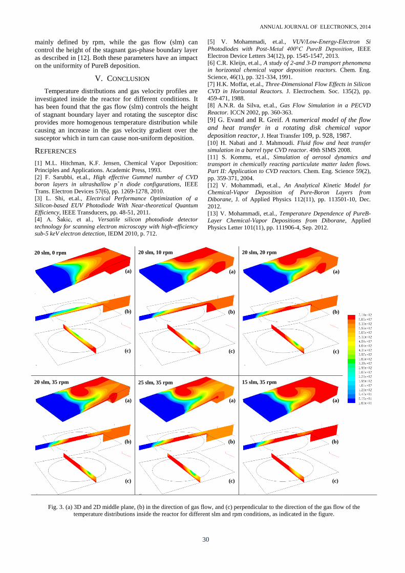
The uniformity of the PureB-layer deposited by this
CVD reactor depends, on one hand, on the uniform
distribution of substrate temperature and on the other hand,
on the flow velocity patterns uniformity near the substrate.
Fig. 3 shows temperature distributions inside the reactor
for different gas flow (slm) and susceptor rotation speed
(rpm) conditions as specified in the figure. The
distributions presented in (a), (b) and (c) are the 3D
illustrations, 2D cross section of the middle plans in
direction of the gas flow and perpendicular to the gas flow
respectively.
At zero rpm (stationary susceptor) a thermal boundary
layer created over the susceptor is clearly visible (“20 slm,0
rpm” b and c in Fig. 3). At this condition the temperature
profile is also symmetrical in the perpendicular plan to the
gas flow with a vertical gradient as can be seen in Fig. 3
“20 slm,0 rpm” (c). This condition is not desired due to a
very narrow thermal boundary layer, with temperature of
deposition over the susceptor, which significantly limits the
number of active precursors for deposition. By rotating the
susceptor the temperature distribution becomes more and
more uniform and the thermal boundary layer expands
vertically over the susceptor where the wafer is located.
This can be seen by comparing the thermal distributions of
Fig. 3 with different rpms at the same slm. It can be
concluded that the temperature distribution becomes more
homogenous at higher susceptor rotation speeds.
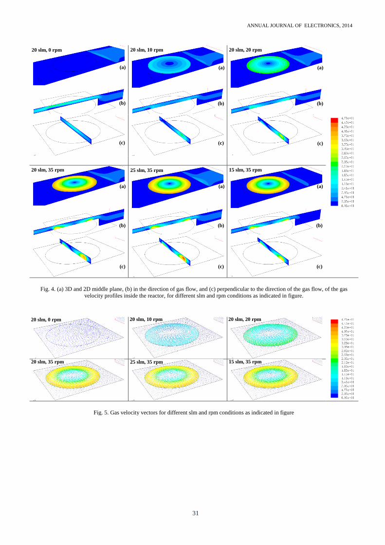
Fig. 4 shows the gas flow profiles determined by 3D
numerical simulations for different rpms and slms as
indicated in the figure. It can be seen that at zero rotation,
the gas flow is laminar and dominated by forced
convection. Rotation of the susceptor disc causes a gas
rotation due to the frictional force between them and makes
a cylindrical disturbance. This disturbance somehow
facilitate the transportation of the reactant precursors to the
substrate while at the same time introduces a gas velocity
gradient over the substrate as can be seen in the images
presented in Fig. 4 (b) and (c). This gradient is increased
with increasing susceptor rotation speed. The direction of
gas rotation and velocity gradient is clearly visible in Fig. 5
where the gas velocity vectors are presented. Beside
cylindrical disturbance, the gas flow is still laminar and
flowed with forced convection. Therefore intermingling
due to free convection can be negligible. The return flow of
heated gas occurring at the leading edge of the hot
susceptor is also visible in all cases in Fig. 4. Gas-phase
diffusion inside the reactor is investigated in ref. [12].
Investigating the images given in Fig. 4 result in the
conclusion that the gas velocity over the susceptor disc is
ANNUAL JOURNAL OF ELECTRONICS, 2014
30
mainly defined by rpm, while the gas flow (slm) can
control the height of the stagnant gas-phase boundary layer
as described in [12]. Both these parameters have an impact
on the uniformity of PureB deposition.
V. CONCLUSION
Temperature distributions and gas velocity profiles are
investigated inside the reactor for different conditions. It
has been found that the gas flow (slm) controls the height
of stagnant boundary layer and rotating the susceptor disc
provides more homogenous temperature distribution while
causing an increase in the gas velocity gradient over the
susceptor which in turn can cause non-uniform deposition.
REFERENCES
[1] M.L. Hitchman, K.F. Jensen, Chemical Vapor Deposition:
Principles and Applications. Academic Press, 1993.
[2] F. Sarubbi, et.al., High effective Gummel number of CVD
boron layers in ultrashallow p+n diode configurations, IEEE
Trans. Electron Devices 57(6), pp. 1269-1278, 2010.
[3] L. Shi, et.al., Electrical Performance Optimization of a
Silicon-based EUV Photodiode With Near-theoretical Quantum
Efficiency, IEEE Transducers, pp. 48-51, 2011.
[4] A. Šakic, et al., Versatile silicon photodiode detector
technology for scanning electron microscopy with high-efficiency
sub-5 keV electron detection, IEDM 2010, p. 712.
[5] V. Mohammadi, et.al., VUV/Low-Energy-Electron Si
Photodiodes with Post-Metal 400°C PureB Deposition, IEEE
Electron Device Letters 34(12), pp. 1545-1547, 2013.
[6] C.R. Kleijn, et.al., A study of 2-and 3-D transport phenomena
in horizontal chemical vapor deposition reactors. Chem. Eng.
Science, 46(1), pp. 321-334, 1991.
[7] H.K. Moffat, et.al., Three‐Dimensional Flow Effects in Silicon
CVD in Horizontal Reactors. J. Electrochem. Soc. 135(2), pp.
459-471, 1988.
[8] A.N.R. da Silva, et.al., Gas Flow Simulation in a PECVD
Reactor. ICCN 2002, pp. 360-363.
[9] G. Evand and R. Greif. A numerical model of the flow
and heat transfer in a rotating disk chemical vapor
deposition reactor, J. Heat Transfer 109, p. 928, 1987. [10] H. Nabati and J. Mahmoudi. Fluid flow and heat transfer
simulation in a barrel type CVD reactor. 49th SIMS 2008.
[11] S. Kommu, et.al., Simulation of aerosol dynamics and
transport in chemically reacting particulate matter laden flows.
Part II: Application to CVD reactors. Chem. Eng. Science 59(2),
pp. 359-371, 2004.
[12] V. Mohammadi, et.al., An Analytical Kinetic Model for
Chemical-Vapor Deposition of Pure-Boron Layers from
Diborane, J. of Applied Physics 112(11), pp. 113501-10, Dec.
2012.
[13] V. Mohammadi, et.al., Temperature Dependence of PureB-
Layer Chemical-Vapor Depositions from Diborane, Applied
Physics Letter 101(11), pp. 111906-4, Sep. 2012.
Fig. 3. (a) 3D and 2D middle plane, (b) in the direction of gas flow, and (c) perpendicular to the direction of the gas flow of the
temperature distributions inside the reactor for different slm and rpm conditions, as indicated in the figure.
20 slm, 0 rpm 20 slm, 20 rpm 20 slm, 10 rpm
15 slm, 35 rpm 25 slm, 35 rpm 20 slm, 35 rpm
(a)
(b)
(c)
(a)
(b)
(c)
(a)
(b)
(c)
(a)
(b)
(c)
(a)
(b)
(c)
(a)
(b)
(c)
ANNUAL JOURNAL OF ELECTRONICS, 2014
31
Fig. 4. (a) 3D and 2D middle plane, (b) in the direction of gas flow, and (c) perpendicular to the direction of the gas flow, of the gas
velocity profiles inside the reactor, for different slm and rpm conditions as indicated in figure.
Fig. 5. Gas velocity vectors for different slm and rpm conditions as indicated in figure
20 slm, 0 rpm 20 slm, 20 rpm 20 slm, 10 rpm
15 slm, 35 rpm 25 slm, 35 rpm 20 slm, 35 rpm
20 slm, 0 rpm 20 slm, 20 rpm 20 slm, 10 rpm
15 slm, 35 rpm 25 slm, 35 rpm 20 slm, 35 rpm
(a)
(b)
(c)
(a)
(b)
(c)
(a)
(b)
(c)
(a)
(b)
(c)
(a)
(b)
(c)
(a)
(b)
(c)