numerical investigation of cold-formed steel purlin in...
TRANSCRIPT

Rakenteiden Mekaniikka (Journal of Structural Mechanics) Vol. 43, No 1, 2010, pp. 12-24
Numerical investigation of cold-formed steel purlin in fire Wei Lu, Pentti Mäkeläinen and Jyri Outinen
Summary. A great deal of researches on steel beam in steel framed structures have indicated that a steel beam can have a substantial fire resistance by alternative load carrying mechanisms, such as catenary action in large deformation, if the large deformation of structure is allowed. However, few researches are available for investigating the behaviour of cold-formed steel purlin in fire. A 3-D finite element model incorporating both geometric and material non-linearity is created to investigate the behaviour of cold-formed Z-shaped steel purlin in fire. It has been shown that due to the thinness of the material and degradation of material properties at elevated temperature, the profile buckles early under thermal expansion. The steel purlin can survive in fire by developing tensile force in large deformation. The catenary force in the structure has a significant role to resist the transversally applied load. No run-away deformation happened before 30 minutes. In addition, the behaviour of Z-shaped purlin of single span and double spans are compared as well.
Key words: cold-formed steel, Z-shaped purlin, structural fire design, catenary action
Introduction Traditionally, the resistance of steel beam in fire is calculated according to flexural bending behaviour with small deflection and without considering the effects of end axial restraints. This practice of evaluating fire resistance of beam is based on standard fire tests on simply supported individual beam. In real structure, the surrounding members restrain the beam both axially and rotationally. With the presence of axial constraints, the beam will behave in catenary action at large deflection stage. The catenary action is a load carrying mechanism where the bending moment capacity of the beam is negligible but the beam will still be able to resist the applied transversal load with the tension force developed in the beam via further deflection even with reduced material strength, [1]-[4]. If large deflection is acceptable in practice, the fire protection might be unnecessary. If the maximum value of axial tension force is well recognized, it will reduce the damage to the surrounding members.
Cold-formed steel purlins have been widely used in industrial buildings to act both as secondary beam to support the roof sheeting and as the bracing member to stabilize the main frame structure. Currently few researches are available on the investigation of behaviour of cold-formed steel purlin in fire. In this paper, a 3D finite element model incorporating both geometric and material non-linearity is created to investigate the behaviour of cold-formed Z-shaped steel purlin in fire. The model has been used to
12

understand the failure mechanism of the purlin and further to investigate effect of number of spans on the behaviour of the purlin.
Geometry of structure The roof construction with lightweight purlin in this research is composed of sandwich panel and Z-shaped purlin as shown schematically in Figure 1 (a). The sandwich panel is connected to the top flange of purlin with roof screw at each panel wave as shown in Figure 1 (b). The purlin is connected to its support member underneath via U-shaped steel console as shown in Figure 1 (c). The steel console is bolted to steel purlin and is welded to the supporting member. The dimensions of Z-shaped steel purlin and U-shaped steel console, and detailed support conditions are shown in Figure 2. The thickness of purlin is 2 mm.
(c)
(a) (b)
Figure 1. Components of a roof construction with lightweight Z-shaped purlin.
Figure 2. Dimensions of purlin and steel console and details of support.
Finite element modelling Four FE models have been created according to the number of span and support conditions. The details are shown in Table 1. Model 1SpanPurlin is created for investigating the behavior of single-span Z-shaped purlin in fire without sandwich panel
13
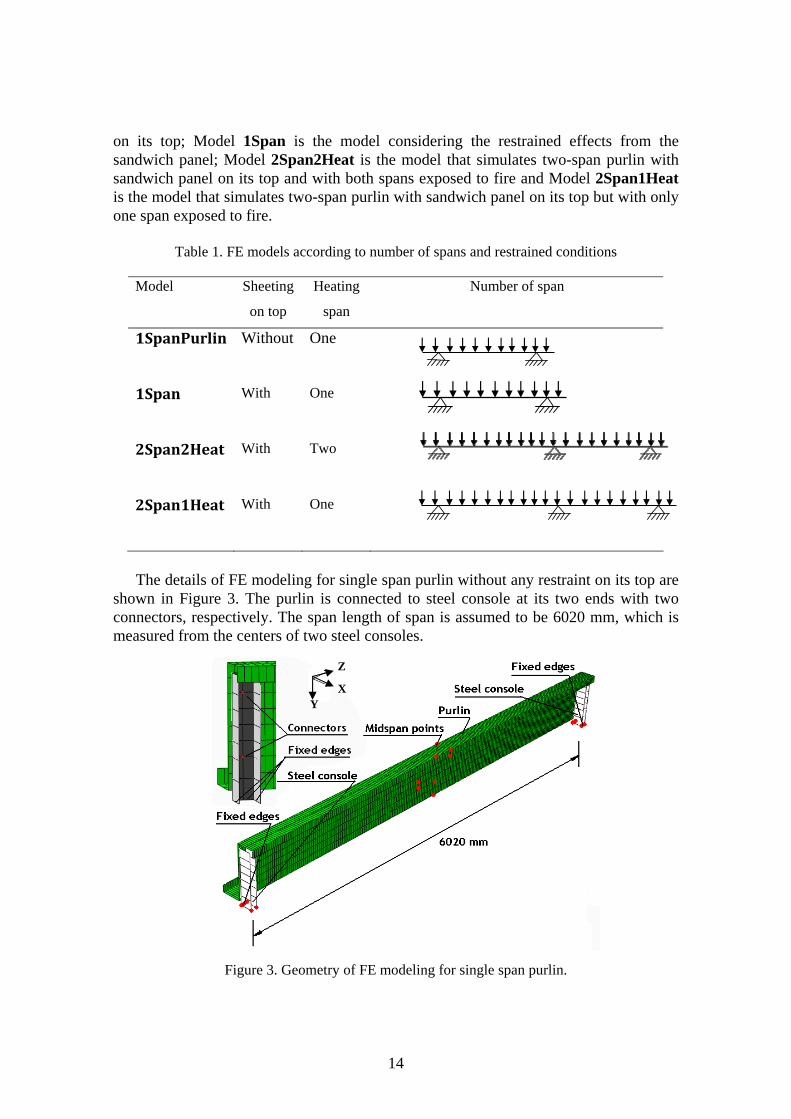
on its top; Model 1Span is the model considering the restrained effects from the sandwich panel; Model 2Span2Heat is the model that simulates two-span purlin with sandwich panel on its top and with both spans exposed to fire and Model 2Span1Heat is the model that simulates two-span purlin with sandwich panel on its top but with only one span exposed to fire.
Table 1. FE models according to number of spans and restrained conditions
Model Sheeting
on top
Heating
span
Number of span
1SpanPurlin Without One
1Span With One
2Span2Heat With Two
2Span1Heat With One
The details of FE modeling for single span purlin without any restraint on its top are
shown in Figure 3. The purlin is connected to steel console at its two ends with two connectors, respectively. The span length of span is assumed to be 6020 mm, which is measured from the centers of two steel consoles.
Y
Z
X
Figure 3. Geometry of FE modeling for single span purlin.
14

The Figure 4 shows the schematic model of purlin with steel sheeting on its top. The steel sheeting is to simulate the restraints coming from the internal facing of sandwich panel with face thickness of 0.5 mm. The purlin is connected to the sheeting with connectors (c/c 334 mm). The width of the plate is assumed to be 750 mm. In order to investigate the effect of the span number on the behavior of purlin in fire, this schematic model has been extended into three types: single span, two-span purlins with both spans heated and two-span purlins with only one span exposed to fire. One span length for these three models is 6020 mm.
Y
Z
X
Figure 4. Geometry of purlin with sheeting on its top.
Material properties The steel grades of steel purlin and steel sheeting are both S350GD+Z with yield strength of 350 N/mm2, modulus of elasticity of 210 000 N/mm2 and density of 7850 kg/m3. The reduction of yield strength at elevated temperature is taken from Annex E in Eurocode 3 Part 1.2. The reduction factor for proportional limit and modulus of elasticity are taken from Eurocode 3 Part 1.2 main text. In Eurocode, the stress-strain curves are given as engineering stress-strain curves. These curves are transferred to true stress and true strain curves via the following equations:
)ln( nomtrue 1 , )1( nomnomtrue . (1)
where true and norm are true strain and engineering strain, respectively; and true and norm are true stress and engineering stress, respectively. In FE modeling the decrease stage in the stress-strain curves are not considered. When the strain is over the maximum strain, the stress values will be kept as constant, i.e. as maximum stress value.
The steel grade of steel console is S355 with yield strength of 355 N/mm2, modulus of elasticity of 210000 N/mm2 and density of 7850 kg/m3. The material properties of
15

console steel are not affected by the increasing of temperature. Thermal elongation of steel at high temperature is defined as that in EN 1993-1-2.
Loading and boundary conditions Two types of loading are applied to the purlin systems: mechanical load and thermal load. The value of mechanical load is 0.73 kN/m2. The load is applied either on the top of sheeting or direct on the flange of purlin depending on the corresponding models. Thermal load is applied as the temperature increase along purlin-sheeting system and across the cross-sections of both purlin and steel sheeting. It is assumed that in this model, the temperatures are uniform in steel purlin and steel sheeting. The temperature rising follows the standard fire curve defined in EN 1993-1-2. The two-step analysis is carried out, i.e. the mechanical loading is applied firstly (step 1) and the temperatures are increased (step 2) secondly as shown in Figure 5.
Figure 5. Loading steps in FE modelling.
Figure 3 and Figure 4 show the details of boundary conditions in FE models. Two steel consoles are clamped along the welded edges. In the direction of span length, the translation degrees of freedom in x-direction along two edges of steel sheeting are fixed to simulate the constraints coming from nearby sheeting that are not included in the model.
Meshing, output and analysis type Commercial FE software, ABAQUS/Explicit [5], is used as an analysis tool. The quasi-static analysis procedure was adopted with a small enough dissipated energy fraction so that the energy fraction has no effects on the behaviour of purlin-sheeting system. Thin shell elements with reduced integration S4R are used to model purlin, steel sheeting and steel consoles. Three dimensional connector elements with 2 nodes (CONN3D2) are used to simulate the connections between sheeting and purlin, and between purlin and steel consoles. The connection-type of connector elements according to ABAQUS is BEAM, which provides a rigid beam connection between two connected nodes, and
16
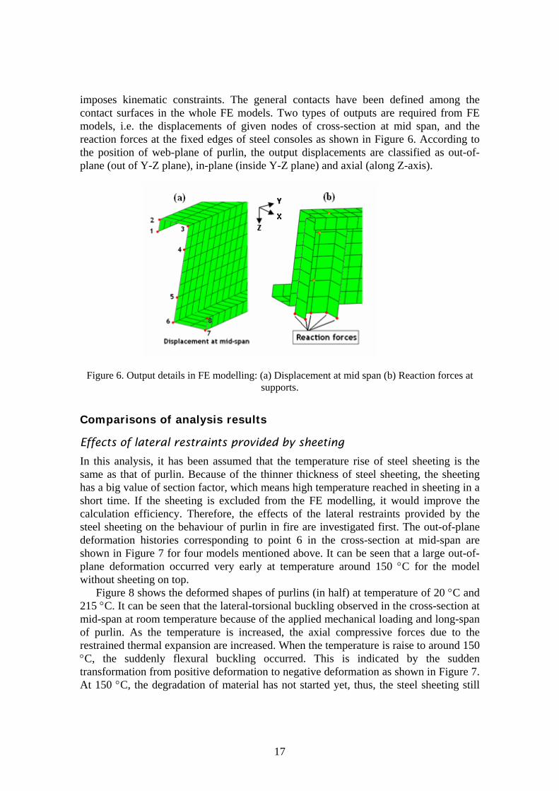
imposes kinematic constraints. The general contacts have been defined among the contact surfaces in the whole FE models. Two types of outputs are required from FE models, i.e. the displacements of given nodes of cross-section at mid span, and the reaction forces at the fixed edges of steel consoles as shown in Figure 6. According to the position of web-plane of purlin, the output displacements are classified as out-of-plane (out of Y-Z plane), in-plane (inside Y-Z plane) and axial (along Z-axis).
Figure 6. Output details in FE modelling: (a) Displacement at mid span (b) Reaction forces at supports.
Comparisons of analysis results Effects of lateral restraints provided by sheeting
In this analysis, it has been assumed that the temperature rise of steel sheeting is the same as that of purlin. Because of the thinner thickness of steel sheeting, the sheeting has a big value of section factor, which means high temperature reached in sheeting in a short time. If the sheeting is excluded from the FE modelling, it would improve the calculation efficiency. Therefore, the effects of the lateral restraints provided by the steel sheeting on the behaviour of purlin in fire are investigated first. The out-of-plane deformation histories corresponding to point 6 in the cross-section at mid-span are shown in Figure 7 for four models mentioned above. It can be seen that a large out-of-plane deformation occurred very early at temperature around 150 C for the model without sheeting on top.
Figure 8 shows the deformed shapes of purlins (in half) at temperature of 20 C and 215 C. It can be seen that the lateral-torsional buckling observed in the cross-section at mid-span at room temperature because of the applied mechanical loading and long-span of purlin. As the temperature is increased, the axial compressive forces due to the restrained thermal expansion are increased. When the temperature is raise to around 150 C, the suddenly flexural buckling occurred. This is indicated by the sudden transformation from positive deformation to negative deformation as shown in Figure 7. At 150 C, the degradation of material has not started yet, thus, the steel sheeting still
17

provide enough lateral restraints to steel purlins against the lateral-torsional buckling, which can be proved from the out-of-plane deformation histories of other models shown in Figure 7. Thus, it is not reasonable to exclude the sheeting in FE modelling. Thus, in the following section, the comparisons are made only for the models with sheeting on the top.
-500-450-400-350-300-250-200-150-100
-500
50
0 100 200 300 400 500 600 700
Def
orm
atio
n [m
m]
Temperature [°C]
1Sp
Pur
2Span1Heat
2Span2Heat
800
an
lin
Figure 7. Comparison of out-of-plane deformation at point 6 for mid-span cross-section.
Z X
Y
Figure 8. Deformed shapes of purlins (half) at temperatures of 20 C and 215 C
18
Deformation histories
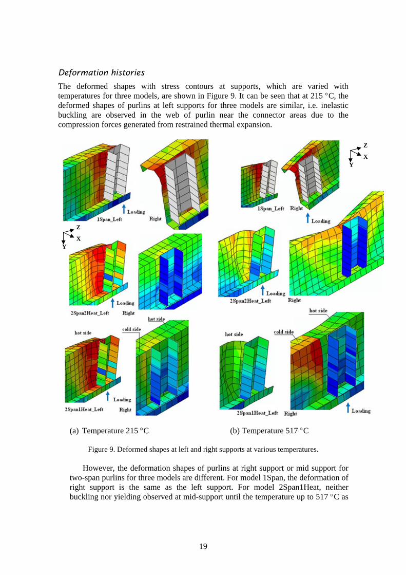
The deformed shapes with stress contours at supports, which are varied with temperatures for three models, are shown in Figure 9. It can be seen that at 215 C, the deformed shapes of purlins at left supports for three models are similar, i.e. inelastic buckling are observed in the web of purlin near the connector areas due to the compression forces generated from restrained thermal expansion.
Z
X Y
Z
X Y
(a) Temperature 215 C (b) Temperature 517 C
Figure 9. Deformed shapes at left and right supports at various temperatures.
However, the deformation shapes of purlins at right support or mid support for two-span purlins for three models are different. For model 1Span, the deformation of right support is the same as the left support. For model 2Span1Heat, neither buckling nor yielding observed at mid-support until the temperature up to 517 C as
19
shown in Figure 9 (b). The local buckling is observed on the flange not connected to the sheeting near the mid-support. This might be because the maximum stresses initially appeared at cold-purlin side at the intersection of “cold” and “hot” purlin. Later the degradation of stiffness at elevated temperature and the high compressive force in this region cause the local buckling of the flange. For model 2Span2Heat, neither yielding nor local buckling of purlin has been observed at mid-support at 215 C. At temperature of 517 C, the purlin flange, which is not connected to steel sheeting, has much larger local buckling than that of model 2Span1Heat.
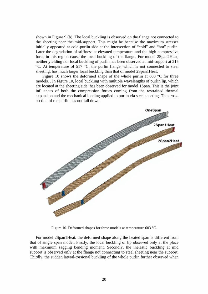
Figure 10 shows the deformed shape of the whole purlin at 603 C for three models. . In Figure 10, local buckling with multiple wavelengths of purlin lip, which are located at the sheeting side, has been observed for model 1Span. This is the joint influences of both the compression forces coming from the restrained thermal expansion and the mechanical loading applied to purlin via steel sheeting. The cross-section of the purlin has not fall down.
Figure 10. Deformed shapes for three models at temperature 603 C.
For model 2Span1Heat, the deformed shape along the heated span is different from that of single span model. Firstly, the local buckling of lip observed only at the place with maximum sagging bending moment. Secondly, the inelastic buckling at mid support is observed only at the flange not connecting to steel sheeting near the support. Thirdly, the sudden lateral-torsional buckling of the whole purlin further observed when
20
the temperature is around 502 C. Comparing to model 2Span1Heat, the model 2Span2Heat has the similar deformation histories. However, the local buckling of purlin at sagging moment area and hogging moment area at mid-support has been observed at lower temperature. Besides, the deformation of model 2Span2Heat occurred at both spans comparing to model 2Span1Heat, whose deformation occurred only in the span exposed to fire.
Out-of-plane displacements
Figure 7 shows the comparisons of out-of-plane deformation of point 6 of cross-section at mid-span for three models. Because of similar deformed shapes at left supports for three models, at temperature of 150 C the initial out-of-plane deformations have been observed for all models. Because of the different deformed shapes at right supports and different heating conditions, the model 2Span1Heat has sudden out-of-plane deformation at around 500 C while the model 2Span2Heat at round 450 C. The out-of-plane deformation for model 1Span increases further after the inelastic buckling at end supports. However, no sudden out-of-plane deformation has been observed for this model. Therefore, the model 1Span has a smaller out-of-plane deformation than those two-span models after the sudden out-of-plane deformation. In-plane displacements
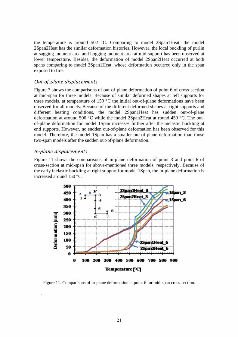
Figure 11 shows the comparisons of in-plane deformation of point 3 and point 6 of cross-section at mid-span for above-mentioned three models, respectively. Because of the early inelastic buckling at right support for model 1Span, the in-plane deformation is increased around 150 C.
Figure 11. Comparisons of in-plane deformation at point 6 for mid-span cross-section.
.
21

Because of the sudden out-o-plane deformation for both model 2Span1Heat and model 2Span2Heat, the sudden in-plane deformations have been observed for these two models at the same temperatures as well. Before that, no buckling occurred near the mid-support, the in-plane deformation for point 3 and point 6 are smaller comparing to the model 1Span. After the lateral-torsional buckling, the flange (Point 3) connecting to the steel sheeting has larger in-plane deformation than that in model 1Span while the flange not connecting to the steel sheeting (Point 6) has smaller in-plane deformation. Axial forces
Figure 12 shows the axial forces at the fixed edges of steel consoles at the left supports for three models. It can be seen that for all models, the axial forces developed are initially compressive due to the restrained thermal expansion; then transferred to tensile forces due to the catenary action of purlin. It can be seen that the maximum compressive occurred at the temperature of 120 C, and then the forces dropped. The dropping is caused by the inelastic buckling at left support. The second dropping occurred at the temperature a little lower than 500 C for model 2Span1Heat and model 2Span2Heat. The second drop is due to the inelastic local buckling at right supports. In addition, the compressive forces are transferred to tensile forces at 500 C for one-span model and at around 560 C for two-span models.
Figure 12. Comparisons of axial forces developed at left support
Conclusions The aim of this research is to investigate the behaviour of cold-formed Z-shaped steel purlin in fire through finite element modelling. Initially four models have been created to consider the effects on the behaviour of purlin, such as lateral restraints provided by
22

steel sheeting, the number of span, and the heating conditions, i.e. one span heating or both span heating. The following conclusions can be drawn:
1. In early stage up to temperature of 150 C, the steel sheeting connected to the flange of purlin provide enough lateral restraints to against lateral-torsional and flexural buckling because of remained strength and stiffness of steel sheeting. Thus, it is reasonable to include the steel sheeting in the model.
2. The compressive forces developed initially at supports due to the restrained thermal expansion. The maximum value has reached at about 120 C. Due to inelastic buckling of purlin at left support, the compressive force is decreased. This has been observed for three all models. Afterwards, inelastic or elastic buckling occurred at mid supports for two-span models, the compressive forces decreased further. For model 2Span1Heat, this has been observed at around 500 C. For model 2Span2Heat, it is at around 444 C. Later, due to the degradation of the material strength and stiffness, the compressive forces decreased dramatically in a short time. At about 500 C for model 1Span, at about 543 C for model 2Span2Heat and at about 564 C, the axial forces changed from compression to tension, the purlins are in catenary action.
3. The purlin heated from two spans behaves similarly to the purlin heated from only one span. The out-of-plane deformation occurred about 50 C earlier for two-span heated purlin than for one-span heated purlin. In addition, the axial reaction forces at mid-support are zero for the purlin heated from two spans because of the symmetric of heating conditions and structures.
4. Comparing to one-span purlins, two-span purlins have smaller both in-plane and out-of-plane deformation due to the delayed local buckling of mid-support. However, when the inelastic buckling occurred at mid-support and sagging moment area, the two-span purlins have sudden out-of-plane deformation and similar in-plane deformation to that of one-span purlin because the degradation of material strength and stiffness is overtaking. As far as the reaction forces at support is concerned, the earlier inelastic buckling at two end supports in one-span purlin actually help to reduce the compressive forces developed at end supports. However, when the purlins are in catenary action, the maximum axial tension forces developed at the supports are the same for both one-span and two-span purlins.
5. The connections should be well investigated further to resist the maximum compressive forces and the tensile forces developed in the later stage since in this research it has been assumed that no failure occurred in connectors.
Acknowledgements This research has been financially supported by Rautaruukki Oyj. Mr. Reijo Lindgren from CSC has been helping when creating the finite element model using ABAQUS. The authors gratefully acknowledge for the supports.
23

24
References [1] A.S, Usmani, J.M, Rotter, S. Lamont, A.M. Sanad, A.M. and M. Gillie,
Fundamental principles of structural behaviour under thermal effects. Fire Safety Journal, 36(8), 721-744, 2001.
[2] Y.Z, Yin and Y.C. Wang, A numerical study of large deflection behaviour of restrained steel beams at elevated temperatures. Journal of Constructional Steel Research, 60(7), 1029-1047, 2004.
[3] M.B., Wong, Modelling of axial restraints for limiting temperature calculation of steel members in fire. Journal of Constructional Steel Research, 61(5), 675-687, 2005.
[4] Y.C, Wang and Y.Z, Yin, A simplified analysis of catenary action in steel beam in fire and implications on fire resistant design. Steel and Composite Structures, 6(5), 367-386, 2006
[5] ABAQUS on-line documentations, version 6.9, 2009.
Wei Lu, Pentti Mäkeläinen, Department of Structural Engineering and Building Technology, School of Science and Technology, Aalto University Rakentajanaukio 4 A, 02150, Espoo [email protected], [email protected]
Jyri Outinen Ruukki Construction, Rautaruukki Oyj P.O.Box 35 (Teknobulevardi 3-5), FI-01531 Vantaa [email protected]