numerical investigation on the energetic...
TRANSCRIPT
Morrone, P., et al.: Numerical Investigation on the Energetic Performances of … THERMAL SCIENCE, Year 2011, Vol. 15, No. 4, pp. 1049-1064 1049
NUMERICAL INVESTIGATION ON THE ENERGETIC
PERFORMANCES OF CONVENTIONAL AND PELLET
AFTERTREATMENT SYSTEMS
IN FLOW-THROUGH AND REVERSE-FLOW DESIGNS
by
Pietropaolo MORRONE and Angelo ALGIERI *
Mechanics Department, University of Calabria, Arcavacata di Rende, Cosenza, Italy
Original scientific paper UDC: 621.43.068:519.23
DOI: 10.2298/TSCI110727103M
The aim of the paper is the analysis of the energetic performances of structured and pelletized aftertreatment systems in flow-through and reverse-flow designs (passive and active flow control, respectively) for Diesel internal combustion en-gines. To this purpose, the influence of the engine operating conditions on the system performances has been investigated adopting a one-dimensional transient model. Specifically, the thermal behaviour and the fuel saving capability of sev-eral arrangements have been characterized. The analysis has shown that the ac-tive emission control system with pelletized design guarantees higher heat reten-tion capability. Furthermore, the numerical model has revealed the significant influence of the solid and exhaust gas temperature on the energy efficiency of the aftertreatment systems and the large effect of exhaust mass flow rate and un-burned hydrocarbons concentration.
Key words: aftertreatment systems, internal combustion engines, energy efficiency, active flow control
Introduction
The technical evolution in the automotive industry has been mainly regulatory-driven.
Specifically, within the last decades engine emissions have been reduced significantly
adopting new aftertreatment strategies [1-5]. To this purpose, a host of investigations has been
focused on oxidation catalysts (OC), diesel particulate filters (DPF), lean NOx traps (LNT),
lean NOx catalysts (LNC), and selective catalytic reductions (SCR) [6-12]. Nevertheless,
further improvements are necessary to meet the more and more stringent exhaust regulations,
to improve the energetic effectiveness of modern emission control systems and to balance
costs and fuel economy benefits.
Nowadays, for the lean burn engine, energy efficient technologies to simultaneously
remove particulate matters (PM), CO, NOx, and HC are not available, and an integration of
different systems is necessary [13-15]. Furthermore, the aftertreatment systems often require
supplemental fuel to assure the proper thermal level for reliable processes and, as a
*nCorresponding author; e-mail: [email protected]

Morrone, P., et al.: Numerical Investigation on the Energetic Performances of … 1050 THERMAL SCIENCE, Year 2011, Vol. 15, No. 4, pp. 1049-1064
consequence, a non-negligible fuel penalty and a deleterious impact on engine efficiency are
produced [13, 14]. As an example, high temperatures are required to regenerate diesel
particulate filters, to initiate and to sustain light-off condition for oxidation catalysts and to
permit the desulfurization process for lean NOx traps [14,16].
Papadakis et al. put forward that there is an increasing trend in the NOx reduction
when the exhaust temperature for heavy-duty Diesel engines raises [17]. Following Johnson
[18], about 50-70% NOx treatment on heavy-duty (HD) Diesel engines will be needed at 500-
520 °C to meet the US NTE (not-to-exceed) regulations, established by the United States
Environmental Protection Agency (US EPA).
In addition, selective catalytic reductions can demand high operating temperatures,
depending both on the base oxides/metals used as active catalysts and on the reducing agents.
Burch et al. showed, for instance, that alumina is very active for C3H6-SCR and selective to
NOx but only at high temperatures (i. e. above 400 °C) [19].
The DPF are very effective in reducing PM emissions. Specifically, DPF tempera-
ture should be raised at approximately 550-600 °C in order to oxidize the trapped PM at a
sufficient rate. As a consequence, a fuel penalty is associated with the regeneration process
(also known as desoot) that ranges from 3 to 4.5%, depending on the desoot frequency
regeneration [20, 21].
Akmadza presented the fuel consumption – NOx trade off curve for different engine
technologies and he demonstrated that there is a 7% increase in the fuel penalty going from a
Euro 5 calibration (0.18 g/km NOx) to a Euro 6 calibration (0.080 g/km NOx) [22]. Papadakis
et al. highlighted that the fuel penalty in NOx reduction experiments is also a function of the
engine speed and torque, with a higher fuel consumption registered at idle condition [17]. At the same time, a fast heat up combustion strategy was proposed by Wada et al.
for the LNC to keep the catalyst hot under cold or low load conditions but an instantaneous 6% fuel penalty was found to get the catalyst 43 °C hotter [23].
Grumbrecht retrofited a Euro 4 sport utility vehicle with SCR behind the DPF to
achieve Euro 6 NOx levels. Preconditioning the catalyst with ammonia storage increased de-
-NOx efficiency by about 20% on the New European Drive Cycle (NEDC) test cycle, with a
4% increase in fuel consumption [24].
In order to reduce the fuel penalty, to increase the energy efficiency and to control
the aftertreatment thermal level more efficiently, an innovative flow control (active control)
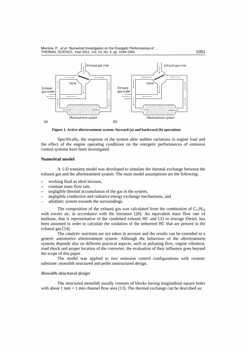
has been developed in the last few years [14, 25]. The active strategy is based on reversed flow converters and on the cyclic inversion
of the exhaust gas between the two system ends (fig. 1). A cycle consists of forward and backward operations and it is defined as symmetric reverse flow if the two consecutive processes last the same time. Conversely, passive flow control represents the technical solution largely adopted in automotive practice with unidirectional flow within the emission control system.
The aim of the present work is the analysis and comparison of the energetic performances of active and passive aftertreatment systems with monolith and pelletized designs. The first system consists of structured monolith beds with several square cross-section thin channels. The second configuration employs randomly packed bed with spherical pellets (unstructured system).
A transient model has been proposed to assess the heat exchange between the solid
and the exhaust gas, to calculate the energy effectiveness of the emission control systems and
to evaluate the potential fuel saving capability of the active system with respect to the passive
mode.
Morrone, P., et al.: Numerical Investigation on the Energetic Performances of … THERMAL SCIENCE, Year 2011, Vol. 15, No. 4, pp. 1049-1064 1051
Specifically, the response of the system after sudden variations in engine load and
the effect of the engine operating conditions on the energetic performances of emission
control systems have been investigated.
Numerical model
A 1-D transient model was developed to simulate the thermal exchange between the
exhaust gas and the aftertreatment system. The main model assumptions are the following:
working fluid as ideal mixture,
constant mass flow rate,
negligible thermal accumulation of the gas in the system,
negligible conductive and radiative energy exchange mechanisms, and
adiabatic system towards the surroundings.
The composition of the exhaust gas was calculated from the combustion of C12H24
with excess air, in accordance with the literature [26]. An equivalent mass flow rate of
methane, that is representative of the combined exhaust HC and CO in average Diesel, has
been assumed in order to calculate the oxidation of the unburned HC that are present in the
exhaust gas [14].
The catalytic reactions are not taken in account and the results can be extended to a
generic automotive aftertreatment system. Although the behaviour of the aftertreatment
systems depends also on different practical aspects, such as pulsating flow, engine vibration,
road shock and proper location of the converter, the evaluation of their influence goes beyond
the scope of this paper.
The model was applied to two emission control configurations with ceramic
substrate: monolith structured and pellet unstructured design.
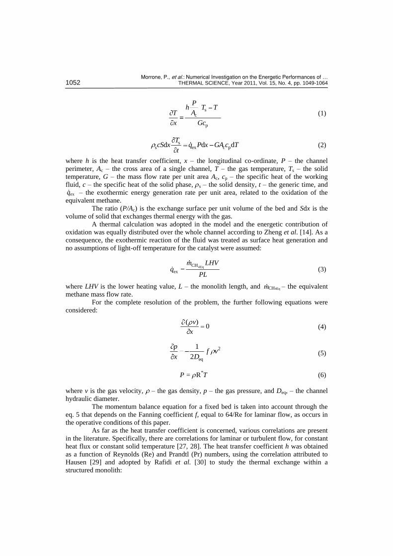
Monolith structured design
The structured monolith usually consists of blocks having longitudinal square holes
with about 1 mm × 1 mm channel flow area [13]. The thermal exchange can be described as:
(a) (b)
Figure 1. Active aftertreatment system: forward (a) and backward (b) operations
Morrone, P., et al.: Numerical Investigation on the Energetic Performances of … 1052 THERMAL SCIENCE, Year 2011, Vol. 15, No. 4, pp. 1049-1064
s
c
p
Ph T T
AT
x Gc
(1)
ss ex c pd d d
TcS x q P x GA c T
t (2)
where h is the heat transfer coefficient, x – the longitudinal co-ordinate, P – the channel
perimeter, Ac – the cross area of a single channel, T – the gas temperature, Ts – the solid
temperature, G – the mass flow rate per unit area Ac, cp – the specific heat of the working
fluid, c – the specific heat of the solid phase, rs – the solid density, t – the generic time, and
exq – the exothermic energy generation rate per unit area, related to the oxidation of the
equivalent methane.
The ratio (P/Ac) is the exchange surface per unit volume of the bed and Sdx is the
volume of solid that exchanges thermal energy with the gas.
A thermal calculation was adopted in the model and the energetic contribution of
oxidation was equally distributed over the whole channel according to Zheng et al. [14]. As a
consequence, the exothermic reaction of the fluid was treated as surface heat generation and
no assumptions of light-off temperature for the catalyst were assumed:
4EqCH
ex
m LHVq
PL (3)
where LHV is the lower heating value, L – the monolith length, and 4EqCHm – the equivalent methane mass flow rate.
For the complete resolution of the problem, the further following equations were
considered:
( )0
v
x (4)
2
eq
1
2
pf v
x D (5)
P = rR*T (6)
where v is the gas velocity, – the gas density, p – the gas pressure, and Deq, – the channel
hydraulic diameter.
The momentum balance equation for a fixed bed is taken into account through the
eq. 5 that depends on the Fanning coefficient f, equal to 64/Re for laminar flow, as occurs in
the operative conditions of this paper.
As far as the heat transfer coefficient is concerned, various correlations are present
in the literature. Specifically, there are correlations for laminar or turbulent flow, for constant
heat flux or constant solid temperature [27, 28]. The heat transfer coefficient h was obtained
as a function of Reynolds (Re) and Prandtl (Pr) numbers, using the correlation attributed to
Hausen [29] and adopted by Rafidi et al. [30] to study the thermal exchange within a
structured monolith:
Morrone, P., et al.: Numerical Investigation on the Energetic Performances of … THERMAL SCIENCE, Year 2011, Vol. 15, No. 4, pp. 1049-1064 1053
eq
eq
2
eq3
0.0668 RePr
Nu 3.61
1 0.04 RePr
DD Lhk D
L
(7)
The equations were solved with a finite difference scheme. More detail on the model
is reported in the literature [31, 32].
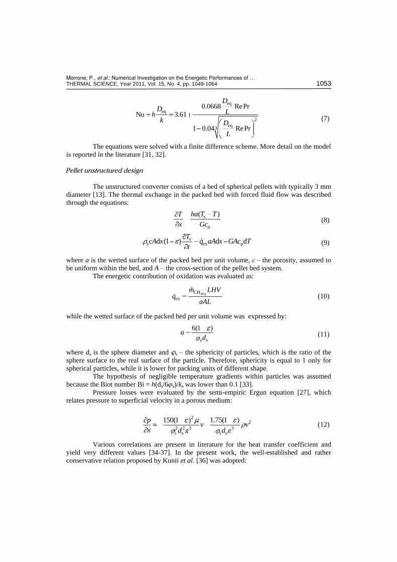
Pellet unstructured design
The unstructured converter consists of a bed of spherical pellets with typically 3 mm
diameter [13]. The thermal exchange in the packed bed with forced fluid flow was described
through the equations:
s
p
( )ha T TT
x Gc (8)
s
s ex pd (1 ) d dT
cA x q aA x GAc Tt
(9)
where a is the wetted surface of the packed bed per unit volume, ε – the porosity, assumed to
be uniform within the bed, and A – the cross-section of the pellet bed system.
The energetic contribution of oxidation was evaluated as:
4EqCH
ex
m LHVq
aAL (10)
while the wetted surface of the packed bed per unit volume was expressed by:
s s
6(1 )a
d (11)
where ds is the sphere diameter and s – the sphericity of particles, which is the ratio of the
sphere surface to the real surface of the particle. Therefore, sphericity is equal to 1 only for
spherical particles, while it is lower for packing units of different shape.
The hypothesis of negligible temperature gradients within particles was assumed
because the Biot number Bi = h(ds/6js)/ks was lower than 0.1 [33].
Pressure losses were evaluated by the semi-empiric Ergun equation [27], which
relates pressure to superficial velocity in a porous medium:
22
2 2 3 3s s s s
150(1 ) 1.75(1 )pv v
x d d (12)
Various correlations are present in literature for the heat transfer coefficient and
yield very different values [34-37]. In the present work, the well-established and rather
conservative relation proposed by Kunii et al. [36] was adopted:

Morrone, P., et al.: Numerical Investigation on the Energetic Performances of … 1054 THERMAL SCIENCE, Year 2011, Vol. 15, No. 4, pp. 1049-1064
1/3 1/2s
g
Nu 2 1.8Pr Rehd
k (13)
with Re > 100.
The model was validated with
experimental results with a good
agreement with respect to the experi-
mental data. The average error for the
gas temperature data was 2%, while
for the bed temperature was lower
than 6% [38].
Operative conditions and perfor-
mance parameters
The geometric characteristics and
the operating conditions of the mono-
lith and pelletized aftertreatment
system are shown in tab. 1 for a
Diesel engine with 6-dm3 displace-
ment and 150 kW power.
To analyse the energy performance
of the emission control system, the
“aftertreatment cooling process” was
examined. Particularly, the initial
solid temperature was set at 700 °C,
while the exhaust gas temperature was
fixed at 200 °C. This corresponds to a
sudden decrease in the engine load
after long full load operation [14].
Therefore, at the beginning of the
cooling process, the emission control
system presents a maximum internal
energy value:
max. s,0E mcT (14)
where m is the solid mass, and Ts,0 – the initial temperature of the solid.
For simplicity, the internal energy is assumed zero when the temperature is equal to
0 K.
The low temperature gas flow determines the progressive cooling of the solid.
Specifically, the minimum energy state corresponds to the complete cooling of the
aftertreatment system:
min. inletE mcT (15)
where Tinlet is the exhaust gas temperature.
The heating process was not considered in the following analysis. In fact, previous
works showed that the active control system is not recommended during the warm-up phase,
if a rapid heating process is required [39, 40].
Table 1. Operative conditions for the working fluid and emission control systems
Reference converter size, H W L
(height, width, length)
141 141 300 mm mm mm
Exhaust flow rate, m 50-200 g/s
Methane mass flow rate, 4EqCHm 0.00-0.30 g/s
Exhaust gas temperature, Tinlet 200-600 °C
Initial solid temperature, Ts 400-700 °C
Solid phase density, s 2807 kg/m3
Solid specific heat capacity, c 800 J/kg K
Monolith design
Cell density, cd 62 cell/cm2
Channel size, b 0.90 mm
Wall thickness, w 0.35 mm
Monolith mass 8.40 kg
Wetted surface per unit volume, Sw/V
2201 m-1
Pellet design
Spheres diameter, ds 3 mm
Porosity, ε 44%
Pellet packed bed mass 9.37 kg
Wetted surface per unit volume, a 1120 m–1

Morrone, P., et al.: Numerical Investigation on the Energetic Performances of … THERMAL SCIENCE, Year 2011, Vol. 15, No. 4, pp. 1049-1064 1055
Stored energy fraction
The evaluation of the aftertreatment energetic performance was achieved through a
dimensionless parameter, the stored energy fraction (SEF) [39-41]:
min.
max. min.
( )E t ESEF
E E (16)
where E(t) is the thermal energy stored in the solid at time t:
s0
( , )d
( )
L
mc T x t x
E tL
(17)
The fraction of the stored thermal energy is a function of time and thus represents a
heat retention efficiency. The SEF parameter permits to compare the thermal characteristics of
different aftertreatment systems (active and passive flow control, structured and unstructured
design), independently of the operating conditions (i. e. exhaust gas temperature, initial solid
temperature) and to evaluate the system response to fast variations in the engine load.
Dimensionless saved fuel
The energy saving capability of the active systems with respect to the passive
control has been also expressed in terms of a potential dimensionless saved fuel (DSF). It
represents the ratio between the fuel that could be saved adopting the active system and the
corresponding engine fuel consumption and it is defined as follows [42]:
savedfuel
0
fuel
dt
m t
DSFm t
(18)
where savedfuelm is the supplemental fuel that should be added to the passive aftertreatment
system to guarantee the same mean temperature of the active apparatus, and fuelm – represents
the corresponding fuel that is burned within the combustion chamber and t is the generic
operating time.
Results
The proposed transient model was adopted to analyze the energetic performances of
emission control systems with active and passive flow control. Furthermore, monolith and
pellet designs were considered. For the reversed flow control mode, a symmetrical thermal
cycle was investigated.
Figure 2 highlights the temperature profiles of solid phase along the monolith and
the pellet packed bed as a function of time for the passive flow control mode.
The exhaust gas temperature is set equal to 200 °C while the initial solid temperature
is 700 °C. This operating condition simulates the exhaust gas at low engine load after a long
period of high load operation [14]. The analysis put in evidence the significant influence of
time on the temperature distribution within the emission control system. The pellet packed
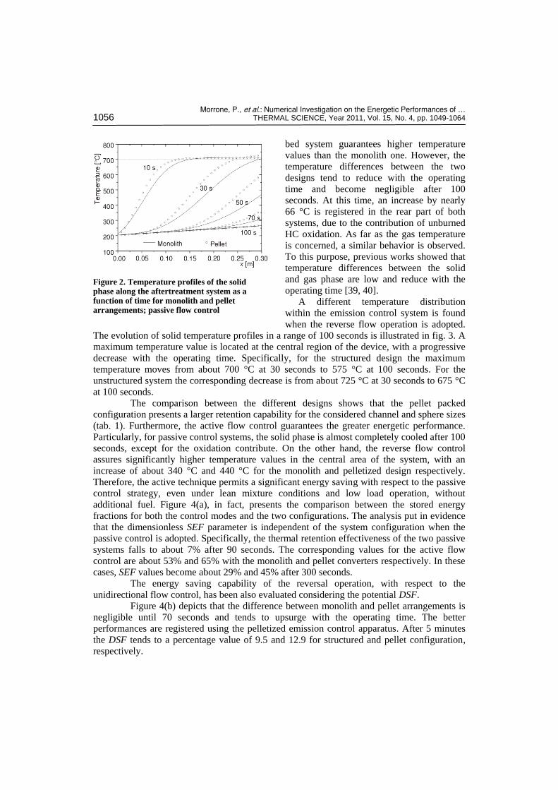
Morrone, P., et al.: Numerical Investigation on the Energetic Performances of … 1056 THERMAL SCIENCE, Year 2011, Vol. 15, No. 4, pp. 1049-1064
bed system guarantees higher temperature
values than the monolith one. However, the
temperature differences between the two
designs tend to reduce with the operating
time and become negligible after 100
seconds. At this time, an increase by nearly
66 °C is registered in the rear part of both
systems, due to the contribution of unburned
HC oxidation. As far as the gas temperature
is concerned, a similar behavior is observed.
To this purpose, previous works showed that
temperature differences between the solid
and gas phase are low and reduce with the
operating time [39, 40].
A different temperature distribution
within the emission control system is found
when the reverse flow operation is adopted.
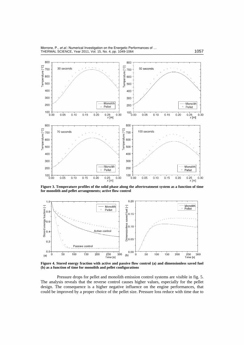
The evolution of solid temperature profiles in a range of 100 seconds is illustrated in fig. 3. A
maximum temperature value is located at the central region of the device, with a progressive
decrease with the operating time. Specifically, for the structured design the maximum
temperature moves from about 700 °C at 30 seconds to 575 °C at 100 seconds. For the
unstructured system the corresponding decrease is from about 725 °C at 30 seconds to 675 °C
at 100 seconds.
The comparison between the different designs shows that the pellet packed
configuration presents a larger retention capability for the considered channel and sphere sizes
(tab. 1). Furthermore, the active flow control guarantees the greater energetic performance.
Particularly, for passive control systems, the solid phase is almost completely cooled after 100
seconds, except for the oxidation contribute. On the other hand, the reverse flow control
assures significantly higher temperature values in the central area of the system, with an
increase of about 340 °C and 440 °C for the monolith and pelletized design respectively.
Therefore, the active technique permits a significant energy saving with respect to the passive
control strategy, even under lean mixture conditions and low load operation, without
additional fuel. Figure 4(a), in fact, presents the comparison between the stored energy
fractions for both the control modes and the two configurations. The analysis put in evidence
that the dimensionless SEF parameter is independent of the system configuration when the
passive control is adopted. Specifically, the thermal retention effectiveness of the two passive
systems falls to about 7% after 90 seconds. The corresponding values for the active flow
control are about 53% and 65% with the monolith and pellet converters respectively. In these
cases, SEF values become about 29% and 45% after 300 seconds.
The energy saving capability of the reversal operation, with respect to the
unidirectional flow control, has been also evaluated considering the potential DSF.
Figure 4(b) depicts that the difference between monolith and pellet arrangements is
negligible until 70 seconds and tends to upsurge with the operating time. The better
performances are registered using the pelletized emission control apparatus. After 5 minutes
the DSF tends to a percentage value of 9.5 and 12.9 for structured and pellet configuration,
respectively.
Figure 2. Temperature profiles of the solid phase along the aftertreatment system as a function of time for monolith and pellet arrangements; passive flow control
Morrone, P., et al.: Numerical Investigation on the Energetic Performances of … THERMAL SCIENCE, Year 2011, Vol. 15, No. 4, pp. 1049-1064 1057
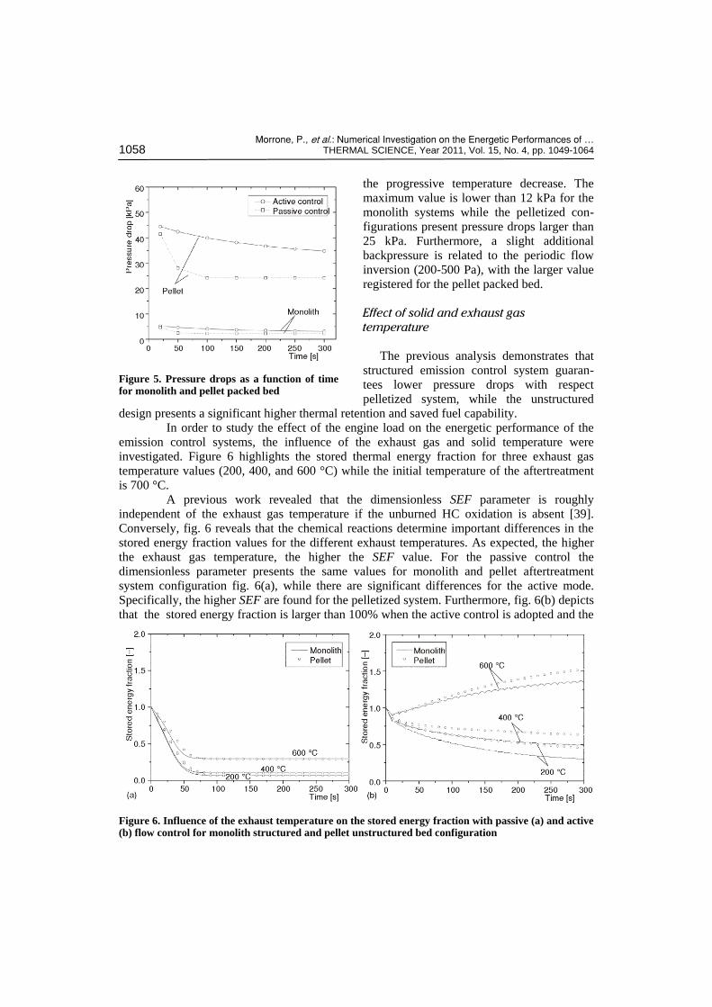
Pressure drops for pellet and monolith emission control systems are visible in fig. 5.
The analysis reveals that the reverse control causes higher values, especially for the pellet
design. The consequence is a higher negative influence on the engine performances, that
could be improved by a proper choice of the pellet size. Pressure loss reduce with time due to
Figure 3. Temperature profiles of the solid phase along the aftertreatment system as a function of time for monolith and pellet arrangements; active flow control
Figure 4. Stored energy fraction with active and passive flow control (a) and dimensionless saved fuel (b) as a function of time for monolith and pellet configurations
Morrone, P., et al.: Numerical Investigation on the Energetic Performances of … 1058 THERMAL SCIENCE, Year 2011, Vol. 15, No. 4, pp. 1049-1064
the progressive temperature decrease. The
maximum value is lower than 12 kPa for the
monolith systems while the pelletized con-
figurations present pressure drops larger than
25 kPa. Furthermore, a slight additional
backpressure is related to the periodic flow
inversion (200-500 Pa), with the larger value
registered for the pellet packed bed.
Effect of solid and exhaust gas
temperature
The previous analysis demonstrates that
structured emission control system guaran-
tees lower pressure drops with respect
pelletized system, while the unstructured
design presents a significant higher thermal retention and saved fuel capability.
In order to study the effect of the engine load on the energetic performance of the
emission control systems, the influence of the exhaust gas and solid temperature were
investigated. Figure 6 highlights the stored thermal energy fraction for three exhaust gas
temperature values (200, 400, and 600 °C) while the initial temperature of the aftertreatment
is 700 °C.
A previous work revealed that the dimensionless SEF parameter is roughly
independent of the exhaust gas temperature if the unburned HC oxidation is absent [39].
Conversely, fig. 6 reveals that the chemical reactions determine important differences in the
stored energy fraction values for the different exhaust temperatures. As expected, the higher
the exhaust gas temperature, the higher the SEF value. For the passive control the
dimensionless parameter presents the same values for monolith and pellet aftertreatment
system configuration fig. 6(a), while there are significant differences for the active mode.
Specifically, the higher SEF are found for the pelletized system. Furthermore, fig. 6(b) depicts
that the stored energy fraction is larger than 100% when the active control is adopted and the
Figure 5. Pressure drops as a function of time for monolith and pellet packed bed
Figure 6. Influence of the exhaust temperature on the stored energy fraction with passive (a) and active (b) flow control for monolith structured and pellet unstructured bed configuration
Morrone, P., et al.: Numerical Investigation on the Energetic Performances of … THERMAL SCIENCE, Year 2011, Vol. 15, No. 4, pp. 1049-1064 1059
exhaust gas temperature is 600 °C. In
fact, the higher efficiency of the reverse
flow operation, the chemical reactions
in the exhaust unburned gas and their
high initial thermal level produce tem-
peratures higher than the initial solid
temperature. In these cases, attention
should be focused on the temperature
distribution within the aftertreatment
apparatus due to the system potential
overheat and/or to the serious aging and
durability problems that could appear
when high temperatures are reached.
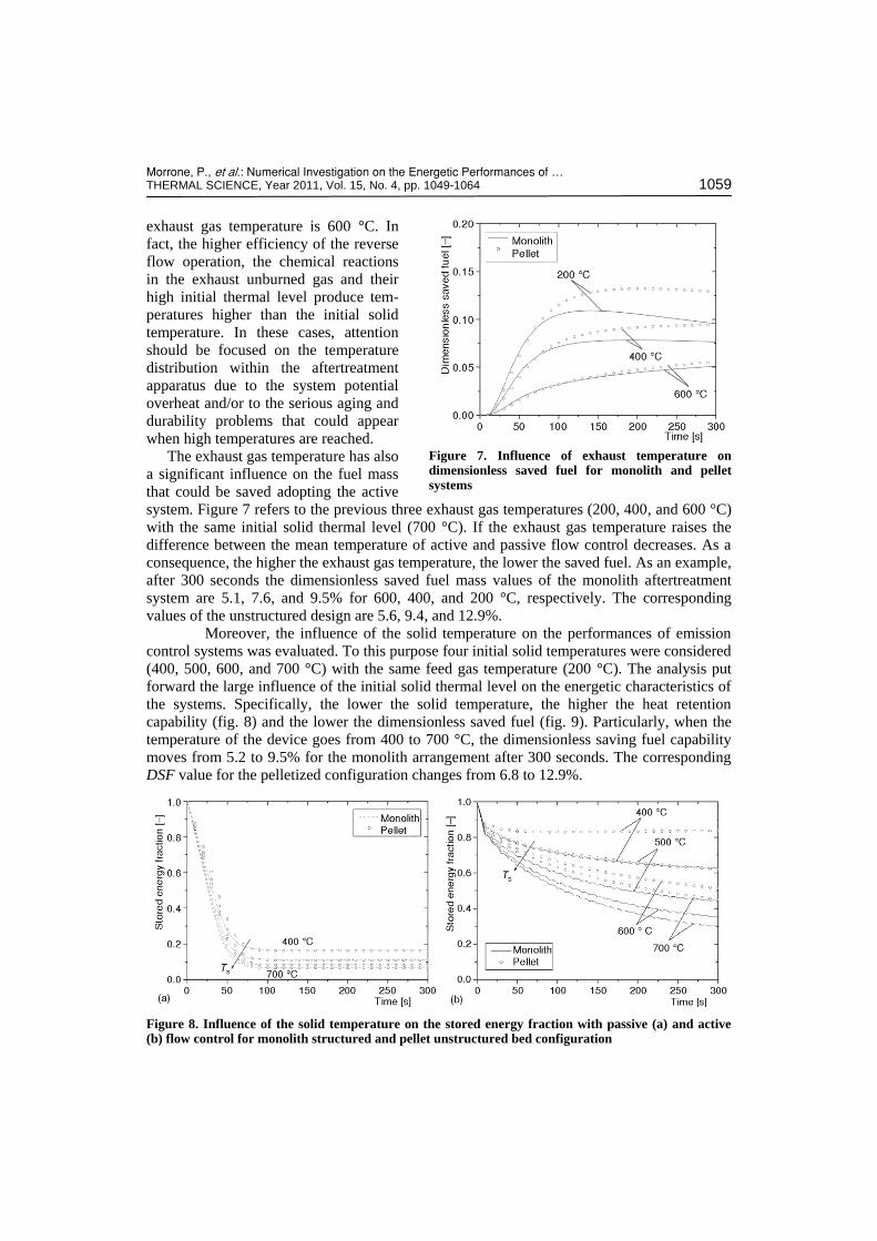
The exhaust gas temperature has also
a significant influence on the fuel mass
that could be saved adopting the active
system. Figure 7 refers to the previous three exhaust gas temperatures (200, 400, and 600 °C)
with the same initial solid thermal level (700 °C). If the exhaust gas temperature raises the
difference between the mean temperature of active and passive flow control decreases. As a
consequence, the higher the exhaust gas temperature, the lower the saved fuel. As an example,
after 300 seconds the dimensionless saved fuel mass values of the monolith aftertreatment
system are 5.1, 7.6, and 9.5% for 600, 400, and 200 °C, respectively. The corresponding
values of the unstructured design are 5.6, 9.4, and 12.9%.
Moreover, the influence of the solid temperature on the performances of emission
control systems was evaluated. To this purpose four initial solid temperatures were considered
(400, 500, 600, and 700 °C) with the same feed gas temperature (200 °C). The analysis put
forward the large influence of the initial solid thermal level on the energetic characteristics of
the systems. Specifically, the lower the solid temperature, the higher the heat retention
capability (fig. 8) and the lower the dimensionless saved fuel (fig. 9). Particularly, when the
temperature of the device goes from 400 to 700 °C, the dimensionless saving fuel capability
moves from 5.2 to 9.5% for the monolith arrangement after 300 seconds. The corresponding
DSF value for the pelletized configuration changes from 6.8 to 12.9%.
Figure 8. Influence of the solid temperature on the stored energy fraction with passive (a) and active (b) flow control for monolith structured and pellet unstructured bed configuration
Figure 7. Influence of exhaust temperature on dimensionless saved fuel for monolith and pellet systems

Morrone, P., et al.: Numerical Investigation on the Energetic Performances of … 1060 THERMAL SCIENCE, Year 2011, Vol. 15, No. 4, pp. 1049-1064
Effect of exhaust gas and unburned
HC mass flow rate
Figures 10 and 11 show the influence of
the exhaust gas flow rate on SEF and DSF
parameters considering the same percen-
tage amount of unburned HC in the exhaust
gas (0.15%). The decrease in stored energy
fraction with operating time is significantly
lower for the active system, due to its
better thermal retention. Furthermore, fig.
10(a) reveals that the asymptotic values for
the passive system are almost the same for
all the investigated exhaust mass flow rates
(about 6.5%), whereas for the active flow
control the lower the exhaust mass flow
rates, the higher the SEF values. After 300
seconds, for the reversal operation, the
stored energy fraction of the monolith
arrangement decreases from about 0.67 to
0.14 when the exhaust flow rate passes from
50 to 200 g/s. The corresponding SEF
values for the unstructured design are 0.71
and 0.21.
The outlined difference between the two
flow control modes is also evident in terms
of dimensionless saved fuel, that upsurges
with the decrease in the exhaust mass flow
rate.
Figure 9. Influence of the solid temperature on the dimensionless saved fuel
Figure 11. Influence of the exhaust mass flow rate on the dimensionless saved fuel
Figure 10. Influence of the exhaust mass flow rate on the stored energy fraction with passive (a) and active (b) flow control for monolith structured and pellet unstructured bed configuration
Morrone, P., et al.: Numerical Investigation on the Energetic Performances of … THERMAL SCIENCE, Year 2011, Vol. 15, No. 4, pp. 1049-1064 1061
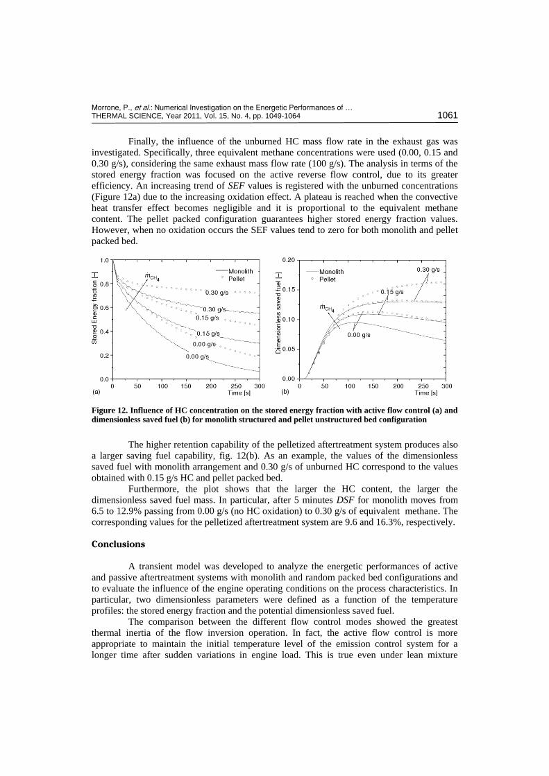
Finally, the influence of the unburned HC mass flow rate in the exhaust gas was
investigated. Specifically, three equivalent methane concentrations were used (0.00, 0.15 and
0.30 g/s), considering the same exhaust mass flow rate (100 g/s). The analysis in terms of the
stored energy fraction was focused on the active reverse flow control, due to its greater
efficiency. An increasing trend of SEF values is registered with the unburned concentrations
(Figure 12a) due to the increasing oxidation effect. A plateau is reached when the convective
heat transfer effect becomes negligible and it is proportional to the equivalent methane
content. The pellet packed configuration guarantees higher stored energy fraction values.
However, when no oxidation occurs the SEF values tend to zero for both monolith and pellet
packed bed.
Figure 12. Influence of HC concentration on the stored energy fraction with active flow control (a) and dimensionless saved fuel (b) for monolith structured and pellet unstructured bed configuration
The higher retention capability of the pelletized aftertreatment system produces also
a larger saving fuel capability, fig. 12(b). As an example, the values of the dimensionless
saved fuel with monolith arrangement and 0.30 g/s of unburned HC correspond to the values
obtained with 0.15 g/s HC and pellet packed bed.
Furthermore, the plot shows that the larger the HC content, the larger the
dimensionless saved fuel mass. In particular, after 5 minutes DSF for monolith moves from
6.5 to 12.9% passing from 0.00 g/s (no HC oxidation) to 0.30 g/s of equivalent methane. The
corresponding values for the pelletized aftertreatment system are 9.6 and 16.3%, respectively.
Conclusions
A transient model was developed to analyze the energetic performances of active
and passive aftertreatment systems with monolith and random packed bed configurations and
to evaluate the influence of the engine operating conditions on the process characteristics. In
particular, two dimensionless parameters were defined as a function of the temperature
profiles: the stored energy fraction and the potential dimensionless saved fuel.
The comparison between the different flow control modes showed the greatest
thermal inertia of the flow inversion operation. In fact, the active flow control is more
appropriate to maintain the initial temperature level of the emission control system for a
longer time after sudden variations in engine load. This is true even under lean mixture
Morrone, P., et al.: Numerical Investigation on the Energetic Performances of … 1062 THERMAL SCIENCE, Year 2011, Vol. 15, No. 4, pp. 1049-1064
conditions and low load operations, without the addition of supplemental fuel. Thus, the
active technique allows significant fuel savings with respect to the passive strategy.
Furthermore, the comparison between different system configurations gave evidence
that the active pellet emission control system guarantees a significantly higher thermal
retention and saved fuel capability with respect to the structured design. On the other hand,
the pelletized system presents larger pressure drops and produces a negative influence on the
engine performances. The proper choice of the pellet size becomes crucial to reduce this
effect and therefore future works will be addressed to the evaluation of this issue.
In addition, the simulations revealed the significant influence of the exhaust gas and
solid temperatures on the stored energy fraction and dimensionless saved fuel, with a larger
effect that was found for the active flow control. For both geometric configurations, SEF
values increase with the exhaust temperature and decrease with the solid temperature. An
opposite trend was observed for the DSF parameter. Finally, the study evidenced the great
impact of the exhaust mass flow rate and unburned HC concentration on the aftertreatment
systems performance. Particularly, the better results were registered with the lower exhaust
flow rate and the higher HC content due to the increasing oxidation effect.
Nomenclature
A – aftertreatment cross area, [m2] Ac – channel cross area, [m2] a – packed bed wetted surface, [m–1] Bi – Biot number, [–] b – channel dimension, [m] c – specific heat of the solid phase, [Jkg–1K–1] cd – cell density, [cell cm–2]; cp – specific heat of the gas, [Jkg–1K–1] Deq – channel hydraulic diameter, [m] DSF – dimensionless saved fuel, [–] ds – sphere diameter, [m] E – internal energy, [J] E(t) – thermal energy at time t, [J] f – fanning friction coefficient, [–]; G – mass flow rate per unit area, [kgs–1m2] h – heat transfer coefficient, [Wm–2K] k – thermal conductivity, [Wm–1K–1] LHV – lower heating value, [Jkg] m – solid mass, [kg]
m – exhaust flow rate, [kgs–1]
4EqCHm – methane mass flow rate, [kgs–1]
fuelm
– burned fuel, [kgs–1]
savedfuelm
– potential saved fuel, [kgs–1] Nu – Nusselt number, [–] P – channel perimeter, [m] p – gas pressure, [Pa] Pr – Prandtl number, [–]
exq – exothermic energy generation, [Wm–2] R* – specific gas constant, [Jkg–1K–1]
Re – Reynolds number, [–]; S – solid surface, [m2] SEF – stored energy fraction, [–] Sw/V – wetted surface per unit volume, [m–1] T – gas temperature, [°C] t – time, [s] Tinlet – inlet gas temperature, [°C] Ts – solid temperature, [°C] v – gas velocity, [ms–1] x – longitudinal coordinate, [m] w – channel thickness, [m]
Greek symbols
e – porosity or void fraction, [–]
s – particle sphericity, [–] m – dynamic viscosity, [kgm–1s–1] r – gas density, [kgm–3]
s – solid density [kgm–3]
Acronyms
DPF – diesel particulate filter EPA – environmental protection agency LNC – lean NOx catalyst LNT – lean NOx trap NEDC – new European drive cycle NTE – not to exceed OC – oxidation catalyst PM – particulate matter SCR – selective catalytic reduction
References
[1] Tan, P. Q., et al., Particulate Mmatter Emission Modelling Based on Soot and SOF from Direct Injection Diesel Engines, Energy Conversion and Management, 48 (2007), 2, pp. 510-518
Morrone, P., et al.: Numerical Investigation on the Energetic Performances of … THERMAL SCIENCE, Year 2011, Vol. 15, No. 4, pp. 1049-1064 1063
[2] Johnson, T. V., Diesel Emission Control in Review, SAE paper 2009-01-0121, 2009 [3] Kesgin, U., Study on Prediction of the Effects of Design and Operating Parameters on NOx Emissions
from a Leanburn Natural Gas Engine, Energy Conversion and Management, 44 (2003), 6, pp. 907-921 [4] Iwamoto, J., et al., Feasibility Study of NOx Reduction with the Active Exhaust Control System when
Engine Starting, Proceedings on CD, FISITA 2010 World Automotive Congress, Budapest, 2010, Code paper F2010-A-023, No. 310
[5] Petrović, V. S., Particulate Matters from Diesel Engine Exhaust Emission, Thermal Science, 12 (2008), 2, pp. 183-198
[6] Pontikakis, G., Stamatelos, A., Three-Dimensional Catalytic Regeneration Modeling of SiC Diesel Particulate Filters, Journal of Engineering for Gas Turbines and Power, 128 (2006), pp. 421-433
[7] Filipi, Z., Hagena, J., Fathy, H., Investigating the Impact of in-Vehicle Transients on Diesel Soot Emissions, Thermal Science, 12 (2008), 1, pp. 53-72
[8] Petković, S. D., Pešić, R. B., Lukić, J. K., Heat Transfer in Exhaust System of a Cold Start Engine at Low Environmental Temperature, Thermal Science, 14 (2010), Suppl., pp. S209-S220
[9] Lehtoranta, K., et al., Diesel Particle Emission Reduction by a Particle Oxidation Catalyst, SAE paper 2009-01-2705, 2009
[10] Kim, D. S., et al., A Study on Characteristics and Control Strategies of Cold Start Operation for Improvement of Harmful Exhaust Emissions in SI Engines, Journal of Mechanical Science and Technology, 22 (2008), 1, pp. 141-147
[11] Ji, Y., et al., NOx Storage-Reduction Characteristics of Ba-Based Lean NOx Trap Catalysts Subjected to Simulated Road Aging, Catalysis Today, 151 (2010), 3-4, pp. 362-375
[12] Kowatari, T., et al., A Study of a New Aftertreatment System (1): A New Dosing Device for Enhancing Low Temperature Performance of Urea-SCR, SAE paper 2006-01-0642, 2006
[13] Heywood, J. B., Internal Combustion Engine Fundamentals, Mc Graw Hill, New York, USA, 1988 [14] Zheng, M., Reader, G. T., Energy Efficiency Analyses of Active Flow Aftertreatment Systems for Lean
Burn Internal Combustion Engines, Energy Conversion and Management, 45 (2004), 15-16, pp. 2473-2493
[15] Güthenkea, A., et al., Development and Application of a Model for a NOx Storage and Reduction Catalyst, Chemical Engineering Science, 62 (2007), 18-20, pp. 5357-5363
[16] Cauda, E., et al., Preparation and Regeneration of a Catalytic Diesel Particulate Filter, Chemical Engineering Science, 62 (2007), 18-20, pp. 5182-5185
[17] Papadakis, K., Odenbrand, C. U. I., Creaser, D., Stationary NOx Storage and Reduction Experiments on a Heavy-Duty Diesel Engine Rig Using a Bypass System, SAE paper 2003-01-1884, 2003
[18] Johnson, T. V., Diesel Emission Control in Review, SAE paper 2006-01-0030, 2006 [19] Burch, R., Breen, J. P., Meunier, F. C., A Review of the Selective Reduction of NOx with Hydrocarbons
under Lean-Burn Conditions with Non-Zeolitic Oxide and Platinum Group Metal Catalyst, Applied Catalysis B: Environmental, 39 (2002), 4, pp. 283-303
[20] Adelman, B., et al., Development and Application of a US-EPA ´07 Particulate Filter System for a 7.6l I-6 Medium Duty Truck Engine, Proceedings, 15th Aachen Kolloquium Fahrzeug- und Motorentechnik, Aachen, Germany, 2006
[21] Parks II, E., et al., Emissions from Premixed Charge Compression Ignition (PCCI) Combustion and Affect on Emission Control Devices, Catalysis Today, 151 (2010), 3-4, pp. 278-284
[22] Akmadza, F., Status of the Euro 5/6 Legislation and Impact on Passenger Cars Engine Development and Aftertreatment Technology, Proceedings on CD, Car Training Institute DPF Forum, Frankfurt, Germany, 2007
[23] Wada, K., et al., Study on Emission Reducing Method with New Lean NOx Catalyst for Diesel Engines, SAE paper 2007-01-1933, 2007
[24] Grumbrecht, F., et al., Concept Development of an SCR Demonstrator Vehicle, Proceedings on CD, Meeting Future European Emission Limits with Low Fuel Consumption. IAV MinNOx Conference, Berlin, 2007
[25] Liu, B., et al., Reversing Flow Catalytic Converter for a Natural Gas/Diesel Dual Fuel Engine, Chemical Engineering Science, 56 (2001), 8, pp. 2641-2658
[26] Singh, P., et al., An Experimental Study of Active Regeneration of an Advanced Catalyzed Particulate Filter by Diesel Fuel Injection Upstream of an Oxidation Catalyst. SAE pape 2006-01-0879, 2006
[27] Perry, R. H., Green, D. W., Perry’s Chemical Eengineers’ Handbook, 7th ed. Mc Graw Hill, New York, USA, 1999
Morrone, P., et al.: Numerical Investigation on the Energetic Performances of … 1064 THERMAL SCIENCE, Year 2011, Vol. 15, No. 4, pp. 1049-1064
[28] Guglielmini, G., Pisoni, C., Heat Transfer Fundamentals (in Italian), Veschi Edizioni, Milano, Italy, 1990
[29] Incropera, F., De Witt, D., Fundamentals of Heat and Mass Transfer, John Wiley and Sons, New York, USA, 2002
[30] Rafidi, N., Blasiak, W., Thermal Performance Analysis on a Two Composite Material Honeycomb Heat Regenerators Used for HiTAC Burners, Applied Thermal Engineering, 25 (2005), 17-18, pp. 2966-2982
[31] Amelio, M., Morrone, P., Numerical Evaluation of the Energetic Performances of Structured and Random Packed Beds in Regenerative Thermal Oxidizers, Applied Thermal Engineering, 27 (2007), 4, pp. 762-770
[32] Amelio, M., et al., The Influence of Rotary Valve Distribution Systems on the Energetic Efficiency of Regenerative Thermal Oxidizers (RTO), International Journal of Energy Research, 32 (2008), 1, pp. 24-34
[33] Duffie, J. A., Beckman, W. A., Solar Engineering of Thermal Processes, Wiley-Interscience Madison, Wis., USA, Publication, 1991
[34] Gupta, A. S., Thodos, G., Direct Analogy between Mass and Heat Transfer to Beds of Spheres, A.I.Ch.E. Journal, 9 (1973), 6, pp. 751-754
[35] Lof, G. O. G., Hawley, R. W., Unsteady State Heat Transfer Between Air and Loose Solids, Industrial and Engineering Chemistry, 40 (1948), 6, pp. 1061-1070
[36] Kunii, D., Levenspiel, O., Fluidization Engineering, 2nd ed., Butterworth-Heinemann, Newton, Mass., USA, 1991
[37] Achenbach, E., Heat and Flow Characteristics of Packed Beds, Experimental Thermal and Fluid Science, 10 (1995), 1, pp. 17-27
[38] Morrone, P., et al., Modelling Process Characteristics and Performance of Fixed and Fluidized Bed Regenerative Thermal Oxidizer (RTO), Industrial & Engineering Chemistry Research, 45 (2006), 13, pp. 4782-4790
[39] Algieri, A., Amelio, M., Morrone, P., A Numerical Analysis of Energetic Performances of Active and Passive Aftertreatment Systems, International Journal of Energy Research, 33 (2009), 7, pp. 696-708
[40] Algieri, A., et al., Active and Passive Aftertreatment Systems: A Numerical Analysis of Energetic Performances, Proceedings on CD, ICAT ’08 Conference, Istanbul, Turkey, 2008, No. 41
[41] Algieri, A., Amelio, M., Morrone, P., Energetic Analysis of the Performances of Innovative Aftertreatment Systems, SAE paper 2009-01-1948, 2009
[42] Algieri, A., Morrone, P., The Influence of the Operating Conditions on the Performances of Innovative Aftertreatment Systems, Proceedings on CD, 12th European Automotive Congress – EAEC 2009, Bratislava, Slovakia, 2009, Code paper 01-040, No. 92
Paper submitted: July 27, 2011 Paper revised: July 27, 2011 Paper accepted: September 16, 2011