numerical investigation on the vertical water-entry …
TRANSCRIPT
31ST INTERNATIONAL SYMPOSIUM ON BALLISTICS HYDERABAD, INDIA, NOVEMBER 4–8, 2019
NUMERICAL INVESTIGATION ON THE VERTICAL
WATER-ENTRY OF A HOLLOW CYLINDER AT LOW VELOCITY
Yu Hou, Zhen-Gui Huang, Zhi-Hua Chen, Ze-Qing Guo and Yu-Chuan Luo
National Key Laboratory of Transient Physics, Nanjing University of Science and
Technology, Nanjing 210094, China
INTRODUCTION
The water entry problem of a solid object impacting on a liquid surface has
challenged researchers for centuries, which is first studied systematically by
Worthington [1] in the 19th century about the air-entraining cavity, splashes and
closure jets of spheres coated with single-flash photography. Then Gilbarg and
Anderson [2] discussed the effect of water-entry velocity and atmospheric pressure on
the entraining cavity evolution of solid spheres. Richardson et al [3] studied the cavity
formation and hydrodynamic resistance to spheres during the vertical water-entry.
After that, May et al. [4, 5] considered extensive factors on the cavity formation with
including the entry speed, atmospheric pressure and sphere radius. The resistance
coefficients of rigid spheres with different radiuses and entry speeds were studied
systematically. Duez et al. [6], Aristoff and Bush [7] investigated the influence of
Based on the volume of fluid (VOF) multiphase flow equations,
the k-ε turbulent model and sliding mesh technique, the low
speed vertical water-entry of a hollow cylinder was investigated
numerically. The numerical results have a good agreement with
corresponding experimental results and finer mesh
independence. The results show that a jet flow induced by the
through-hole provides a new connection between the inner and
outer flow at the pinch-off time underwater. Furthermore, a little
bubble on the top of the through-hole jet is created by the
collision of the edge surface of the water column inside the
cylinder. The initial water-entry speed has a significant
influence on the inner cavity formation, the pinch-off depth, the
through-hole jet ejection and the motion parameter during the
vertical water-entry process.
Keywords: Vertical water-entry, Hollow cylinder, Numerical
simulation, Low water-entry speed, Multiphase flow
1171
hydrophilic and hydrophobic surface of spheres on the cavity formation respectively
by conducting controlled experiments.
The structure and material of entry model are studied more extensively on recent
researches to meet the practical needs. Chen [8] studied entry cavity flow
characteristics of projectiles with three warhead shapes at different entry speed. He [9]
carried out water entry experiments on the cylinder with various initial velocity and
attitudes. Truscott et al. [10] reviewed the experimental researches on spheres and
slender bodies with cone, cusp, ogive and flat heads. Lu et al. [11] studied the vertical
water entry of a semi-closed cylinder experimentally, which illustrated the
hydrodynamic characteristics of fluctuation cavitation pattern when the water poured
to the cylindrical shell.
The theoretical work of water entry problem is carried out by von Karman [12]
and Wagner [13], who investigated the phenomenon related to the impact of objects
on liquid surfaces. They considered the solid body entering a fluid at large Reynolds
and Weber numbers, where viscosity and surface tension were neglected. In the recent
years, there has been a growing interest in the physics of impact, particularly due to the
development of computer. Greenhow [14] simulated the free surface deformations of
initially calm water caused by the impact of a horizontal circular cylinder by using a
nonlinear two-dimensional numerical calculation. Lin [15] developed a
two-dimensional numerical model to simulate a moving body in a free surface flow
based on the cut-cell technique in a fixed-grid system, and the volume of fluid (VOF)
method was applied to track interface.
Compared to solid objects on the above researches, few studies on the water entry
problem of hollow structures are carried out. According to the published work,
Tseitlin [16] first proposed that the solution of the plane problem of flow past two flat
plates be extended to flow past the disc with a hole. Deinekin [17] numerically solved
the problem of axisymmetric flow past a ducting cavitator. Savchenko [18] studied the
resistance characteristics of disc cavitation with different apertures through water
tunnel experiments. The free-surface impact of hollow structure results in complex
flow fields both inside and outside, which has more study challenges involved in
multiphase flow than hollow projectiles [19] in the air. Meanwhile, several parameters
of the through-hole in the structure such as size, quantity, pattern and opening position
will affect the navigation resistance, the stealth and the trajectory stability of the
vehicle underwater.
Therefore, the investigation on the water-entry of hollow structures is of great
significance for the design and improvement of airdrop torpedoes and sonar buoys,
drainage holes and discharge orifices of a submarine, etc. In this paper, the water entry
of a hollow cylinder is investigated by numerical simulation. The numerical and
experimental results are compared to validate the numerical method. Then several
cases of the water entry with the increasing entry speed are illustrated. The trajectories,
velocities, accelerations of the cylinder and the drag coefficient during water entry are
also investigated.
1172

NUMERICAL MODEL
Governing equations
The VOF model in the form of Reynolds-averaged Navier-Stokes equations is
applied to describing the vertical water-entry cavities. The continuity equation for
the mixture flow is
( )0
m jm
j
u
t x
(1)
Where ρm=(1-αwater) ρair+αwater ρwater represents the mixture density. ρair and
ρwater represent the air density and water density respectively. The water volume
fraction αwater= 0.5 at the boundary between the air and water.
The momentum equations for the mixture flow is
( )[( )( )]
m i j jm i im i m t
j i j j i
u u uu uPg
t x x x x x
(2)
where gi represents the gravity acceleration in xi coordinate. P represents the
mixture pressure. μm=(1-αwater) μair +αwater μwater represents the mixture dynamic
viscosity coefficient and μt is the turbulent viscosity.
The two equation realizable k-ε turbulence model is used to set the viscous
equation closed. The turbulent kinetic transport equation is
( ) ( )[( ) ]m m i t
k b m M k
i i k i
k ku kG G Y S
t x x x
(3)
The transport equation of dissipation rate of energy from the turbulent flow is 2
1 2 1 3
( ) ( )[( ) ]m m i t
b
i i i
uC S C C C G S
t x x x kk
(4)
Where 1 max[0.43, ]5
C
,
kS
, 2 ij ijS S S .
In these equations, Gk and Gb represent the generation of turbulence kinetic
energy due to the mean velocity gradients and buoyancy respectively. YM represents
the contribution of the fluctuating dilatation in the compressible turbulence to the
overall dissipation rate. C2 and C1ε are constants. σk and σε are the turbulent prandtl
numbers for k and ε, respectively. Sk and Sε are source terms.
Model schematic and computational domain
The hollow projectile is simplified to a tubular cylinder in Fig.1 and specific
dimension is shown in Table 1. As shown in Fig.2, an axisymmetric
two-dimensional plane(15D×45D) was designed for the computational domain.
The water depth is 30D and the test model falls freely at the height of 1.25D from
the water surface in gravity. The operating pressure P0 is 101325Pa. The stationary
wall was chosen for both side and bottom boundary. The top boundary is
pressure-inlet. The impact time and the water-entry location are defined as the
origin of time and x coordinate respectively.
1173

In the present paper, the structured mesh is employed throughout the whole
domain for the mesh generation using the commercial software ANSYS ICEM, as
shown in Fig.3. The grid dimension increases gradually from the cylinder boundary
to the domain boundary. The mesh contains 906322 elements and the minimum
mesh size is 2.14×10⁻⁴
m.
Figure 1. Schematic of the hollow cylinder.
TABLE 1. DETAILS OF THE HOLLOW CYLINDER.
D
(mm)
d
(mm)
d/D
L
(mm)
M
(kg)
30.0 25.3 0.84 80.0 0.128
Numerical Treatment
The numerical simulations were carried out by using ANSYS FLUENT
software to solve Reynolds-Averaged Navier-Stokes (RANS) equations. The above
time-dependent governing equations are discretized by using the finite volume
method, and the SIMPLE scheme is used to solving the pressure-velocity coupling
algorithms. The second order upwind scheme is used for the convection terms and
the central-difference for the diffusion term in the momentum equations. The
PRESTO (pressure staggering option) scheme is used for the pressure interpolation.
The Geo-Reconstruct scheme is used for the transport equation for the volume
fractions. The Realizable k-ε model with standard wall functions is carried out in
the software FLUENT.
Figure 2. The computational domain and boundary conditions.
1174
Figure 3. Mesh structure.
RESULTS AND DISCUSSION
Numerical Validation
The simulation results are compared directly with corresponding experimental
results to validate the numerical methodology and meanwhile establish the grid
independence in the present paper in Fig.4. The experimental result in Fig.4(a) and
simulation results with increasing resolutions in Fig.4(b)~(g) at 25ms with the
initial water-entry speed v0=2.84m/s are present together. As illustrated in this case,
a subsurface air cavity surrounds the hollow cylinder and a jet with a top bubble
ejects through the hole after water entry. The numerical results agree well with the
experiment results on the jets structure and splash shapes.
Figure 4. Comparison of cavity formation and splash of experiment and simulation with different
resolutions at 25ms.
In order to establish the grid independence, the number of the computational
mesh elements increases from 0.46 million to 2.7 million and the grid size of the
boundary layer is refined from 3.92×10⁻⁴
m to 0.90×10⁻⁴
m, as shown in Fig.4(b)~(g).
The air cavity and splash have a clearer shape with the increasing numerical
1175
resolution. The little bubble on the top of the through-hole jet is captured clearly in
the simulation with mesh elements more than 0.9 million. No essential changes in
the water-entry process are found with the further refinement except the
discontinuous boundary of the top bubble within the margin of error. The volume
and stretch shape of the through-hole jet and bubble remain the same approximately.
Moreover, the experimental and the numerical depth of the hollow cylinder
with the increasing mesh quantity is shown in Fig.5. The results show that the
numerical motion of the hollow cylinder has the same trend as the experiment. The
depth error is reduced with the further refinement but the enormous computational
cost must be solved. After comparing the cavity shape and the hollow cylinder depth,
the finer mesh with 906322 elements is found to be applicable to improve simulated
efficiency in the present paper.
Figure 5. Comparison of the experimental and the numerical depth of the hollow cylinder with the
increasing mesh quantity.
The entry cavity evolution with the increasing entry velocity
To investigate the air entraining cavity of the hollow cylinder with low vertical
entry speed, the water-entry process was simulated. The entry speed v0 is increased
from 0.90m/s to 2.84m/s. Three typical cases of the vertical water-entry cavity
evolution with entry speed v0=0.90, 1.90, 2.84m/s are shown in Fig.6(a)~(c)
respectively. The origin time (t=0ms) of the image record is defined as the impact
moment. Four distinct stages are considered following the discussions of May [5]
and Truscott et al. [10] the impact stage, the open cavity and jets growth stage, the
pinch-off stage and the sailing stage with cavity attached.
When the hollow cylinder impacts the water surface, the autogenic succession
of energy transfer makes the flow around the cylinder head obtain oblique inward
and upward velocity, therefore, a jet inside the hole and a surrounding air cavity
forms in the open cavity and jets growth stage respectively. The pierced flow moves
backward to be the through-hole jet that has a regular geometric shape and an
attached spherical bubble at the top. The surrounding flow expand outward to be an
1176

axisymmetric air entraining cavity that wraps the cylinder. The pinch-off stage
comes after the expansion end and the shrink beginning of the cavity wall with the
potential energy of the fluid nearby transformed into the kinetic energy.
Then the cavity wall pinches off at a point on the through-hole jet or the bottom
of the cylinder due to different entry velocities. Compared with the traditional deep
closure at a point [5,9] under the free surface, the extrusive jet column inside the
hole provides a further connection of the pierced flow and the surrounding flow and
creates an annular bubble covering the through-hole column occurs when the closed
cavity is cut off at the bottom of the cylinder. Finally, in the sailing stage with cavity
attached, semi-closed surrounding cavity and two lathy “tails” of the shedding
bubbles are found in the side view after the annular bubble was stretched.
(a) Cavity evolution at the entry speed v0=0.90m/s
(b) Cavity evolution at the entry speed v0=1.90m/s
1177

(c) Cavity evolution at the entry speed v0=2.84.m/s
Figure 6. Three typical cases of the vertical water-entry cavity of the hollow cylinder with the
increasing entry speed.
However, some specific flow changes are found with the increasing entry speed.
First, there is no internal cavity on the through-hole wall when the entry speed is
0.90m/s, as shown in Fig.6(a) and Fig.7(a). The internal cavity forms and the volume
of the cavity increases gradually when the entry speed grows larger than 1.30m/s,
which is testified by changes of the dimensionless length lc/D shown in Fig.8(c) with
the increasing entry speed. The length lc of the internal cavity at the first pinch-off
time is defined in the partial enlargement(Fig.7(g)).
Moreover, the depth l of the pinch-off point defined in Fig.7(c)(f) and the
maximum size dc of the air cavity defined in Fig.7(d) at the pinch-off time are in a
positive correlation significantly with water entry speeds shown in Fig.8(a)(b). The
pinch-off point moves upward from the first half of the outer wall to the bottom of it
gradually with the increasing entry speed in Fig.7(a)~(f). The more kinetic energy
transfer from the impact cylinder with higher entry speeds results in the more larger
expansion of the air cavity wall and the postpone of the pinch-off. Furthermore, the
increase of the ejection velocity of through-hole jets and the volume of top bubbles at
the pinch-off time is observed with the rise of entry speeds in the Fig.7.
1178

Figure 7. Comparison of the attached cavity in numerical and experimental results.
(a) (b) (c)
Figure 8. (a)The non-dimensional depth of closure points, (b)the maximum diameter of cavities and
(c)the length of internal cavities at the first pinch-off time with the increasing entry speed.
In conclusion, the through-hole jets with top bubbles induced by the hollow
structure during the water-entry process establish a new form of cavity wall
shrinking change the seal mode of cavity wall comparing the traditional deep
closure. The annular bubble following little shedding bubbles forms on the bottom
of the moving body. Meanwhile, the entry speed has an obvious influence on the
inner cavity formation, the pinch-off depth and the through-hole jet ejection.
Motion characteristics of the hollow cylinder with the increasing velocity
Main parameters of the hollow cylinder motion are shown in Fig.9(a)~(d),
which include the transient displacement x, velocity v, acceleration a and
dimensionless parameter v/v0. The transient displacement x, velocity v and
acceleration a are obtained from the numerical results. The drag coefficient
Cd=F/(0.5ρv2A) changes with the increasing entry speed are present in Fig.10,
where the total resistance is calculated by F=-Ma+Mg.
1179
(a) (b)
(c) (d)
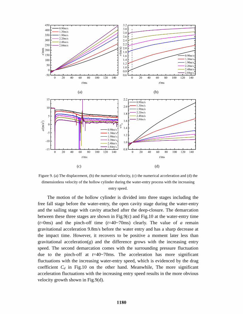
Figure 9. (a) The displacement, (b) the numerical velocity, (c) the numerical acceleration and (d) the
dimensionless velocity of the hollow cylinder during the water-entry process with the increasing
entry speed.
The motion of the hollow cylinder is divided into three stages including the
free fall stage before the water-entry, the open cavity stage during the water-entry
and the sailing stage with cavity attached after the deep-closure. The demarcation
between these three stages are shown in Fig.9(c) and Fig.10 at the water-entry time
(t=0ms) and the pinch-off time (t=40~70ms) clearly. The value of a remain
gravitational acceleration 9.8m/s before the water entry and has a sharp decrease at
the impact time. However, it recovers to be positive a moment later less than
gravitational acceleration(g) and the difference grows with the increasing entry
speed. The second demarcation comes with the surrounding pressure fluctuation
due to the pinch-off at t=40~70ms. The acceleration has more significant
fluctuations with the increasing water-entry speed, which is evidenced by the drag
coefficient Cd in Fig.10 on the other hand. Meanwhile, The more significant
acceleration fluctuations with the increasing entry speed results in the more obvious
velocity growth shown in Fig.9(d).
1180

Figure 10. The numerical drag coefficient of the hollow cylinder with the increasing entry speed.
CONCLUSION
Numerical investigations on the low speed vertical water-entry of hollow
cylinders with the increasing entry speeds were carried out. The simulation has
good agreements in comparison with corresponding experimental data and finer
mesh independence. Some insights into the flow characteristics during the water
entry were predicted in consideration of the solid cylinder in reality. For the vertical
water-entry hollow cylinders, a through-hole slender jet with a top bubble included
near its head is created due to the collision of the edge surface of the water column.
And it establishes a new form of cavity wall shrinking changing the deep closure
pattern from a point closure to a horizontal circular arc closure underwater
comparing the traditional deep closure. An annular bubble following little shedding
bubbles forms on the bottom of the moving body. Meanwhile, the entry speed has
an obvious influence on the inner cavity formation, the pinch-off depth and the
through-hole jet ejection. The motion parameter modifications of the vertical
water-entry hollow cylinder are divided into three stages by the entry point and the
closure point, the free fall stage before the water-entry, the open cavity stage during
the water-entry and the sailing stage with cavity attached.
ACKNOWLEDGMENTS
This work is supported by "the Key Laboratory Fund"
No.61426040303162604004 and No.614260403041803, "the Fundamental
Research Funds for the Central Universities" No.30917012101 and "the
Postgraduate Research & Practice Innovation Program of Jiangsu Province"
No.KYCX19_0259.
1181

REFERENCES:
1. Worthington A M. 1882. "On Impact with a Liquid Surface" Proceedings of the Royal Society of
London, 34(220): 217-230.
2. Gilbarg D, Anderson R A. 1948. "Influence of atmospheric pressure on the phenomena
accompanying the entry of spheres into water" Journal of Applied Physics, 19(2): 127-139.
3. Richardson E G. 1948. "The impact of a solid on a liquid surface" Proceedings of the Physical
Society, 61(4): 352.
4. May A, Woodhull J C. 1950. "The virtual mass of a sphere entering water vertically" Journal of
Applied Physics, 21(12): 1285-1289.
5. May A. 1952. "Vertical entry of missiles into water" Journal of Applied Physics, 23(12): 1362-1372.
6. Duez C, Ybert C, Clanet C, Bocquet L. 2007. "Making a splash with water repellency" Nature
physics, 3(3): 180-183.
7. Aristoff J M, Bush J W M. 2009. "Water entry of small hydrophobic spheres" Journal of Fluid
Mechanics, (619): 45-78.
8. Chen X. 1985. "Experimental studies on the cavitation phenomena as a pellet entering water"
Explosion and Shock Waves, 5(04): 70-73.
9. He C T. 2012. "Low speed water-entry of cylindrical projectile" Acta Physica Sinica, 61(13):
134701.
10. Truscott T T, Epps B P, Belden J. 2014. "Water Entry of Projectiles" Annual Review of Fluid
Mechanics, 46(1): 355-378.
11. Lu Z L, Wei Y J, Cong W, Zhao S, Astronautics S O. 2016. "An experimental study of water-entry
cavitating flows of an end-closed cylindrical shell based on the high-speed imaging technology" Acta
Physica Sinica, 65(1): 14704.
12. Von Karman T. 1929. "The impact on seaplane floats during landing". NACA Technical Report 321.
13. Wagner H. 1932. "Phenomena associated with impacts and sliding on liquid surfaces" Z. Angew.
Math. Mech, 12(4): 193-215.
14. Greenhow M. 1988. "Water-entry and-exit of a horizontal circular cylinder" Applied Ocean
Research, 10(4): 191-198.
15. Lin P. 2007. "A fixed-grid model for simulation of a moving body in free surface flows" Computers
& fluids, 36(3): 549-561.
16. Tseitlin M. 1959. "On the pressure on two parallel plates in a jet flow" TsAGI Transactions on
Hydrodynamics, 01(01): 296-308.
17. Deinekin P. 1994. "Cavity flow past flow passage bodies" Gidromekhanika, 01(68): 74-78.
18. Savchenko G Y. 2012. "Hydrodynamic Characteristics of a Disc with Central Duct in a
Supercavitation Flow". Berlin: Springer Berlin Heidelberg, pp. 107-113.
19. Sahu J, Heavey K R. 1996. "Chapter 41 - High performance parallel computing CFD simulations of
projectiles with flow control". Parallel Computational Fluid Dynamics 2004, Winter G, Ecer
AandFox P, et al, Amsterdam: Elsevier Science, 329-337.
1182