numerical investigations of seismic resonance phenomena in fluid-filled layers hans f. schwaiger and...
TRANSCRIPT

Numerical Investigations of Seismic Resonance Phenomena in Fluid-Filled Layers
Hans F. Schwaiger and David F. Aldridge
Geophysics Department
Sandia National Laboratories
Albuquerque, New Mexico, USA
Seismological Society of America 2008 Annual Meeting
Sante Fe, New Mexico
April 16-18, 2008
Sandia is a multiprogram laboratory operated by Sandia Corporation, a Lockheed Martin Company,for the United States Department of Energy’s National Nuclear Security Administration
under contract DE-AC04-94AL85000.
• Numerical Algorithm– Features and limitations
• Problem formulation• Preliminary results• Conclusions and ongoing work
Outline

• 1-D Layered Model– N layers, 2 half-spaces
– Homogeneous, isotropic, anelastic
– Welded interfaces between layers
Layered Earth Model
interfacedepth
x
yz
1
2
n-1
n
n+1
N
N+1
0
layer #
2
3
n-1
n
n+1
N
N+1
1
interface #
z2
z3
zn-1
zn
zn+1
zN
zN+1
z1
. . .
. . .
. . .
. . .
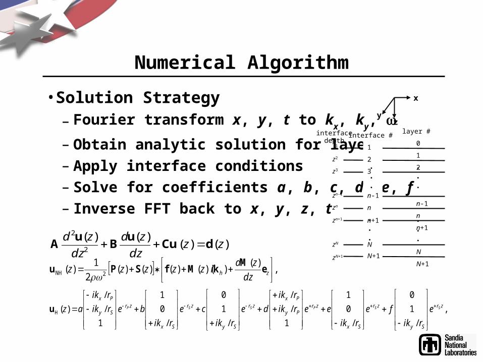
• Solution Strategy
– Fourier transform x, y, t to kx, ky,
– Obtain analytic solution for layers
– Apply interface conditions
– Solve for coefficients a, b, c, d, e, f
– Inverse FFT back to x, y, z, t
Numerical Algorithm
interfacedepth
x
yz
1
2
n-1
n
n+1
N
N+1
0
layer #
2
3
n-1
n
n+1
N
N+1
1
interface #
z2
z3
zn-1
zn
zn+1
zN
zN+1
z1
. . .
. . .
. . .
. . .
)()()()(
2
2
zzdz
zd
dz
zddCu
uB
uA
,
/
1
0
/
0
1
1
/
/
/
1
0
/
0
1
1
/
/
)(Hzr
Sy
zr
Sx
zrPy
Pxzr
Sy
zr
Sx
zrSy
Px
SSPSSP e
rik
fe
rik
eerik
rik
de
rik
ce
rik
berik
rik
az
u
,)(
))(()()()(2
1)(
2NH
zh dz
zdizzzzz e
MkMfSPu
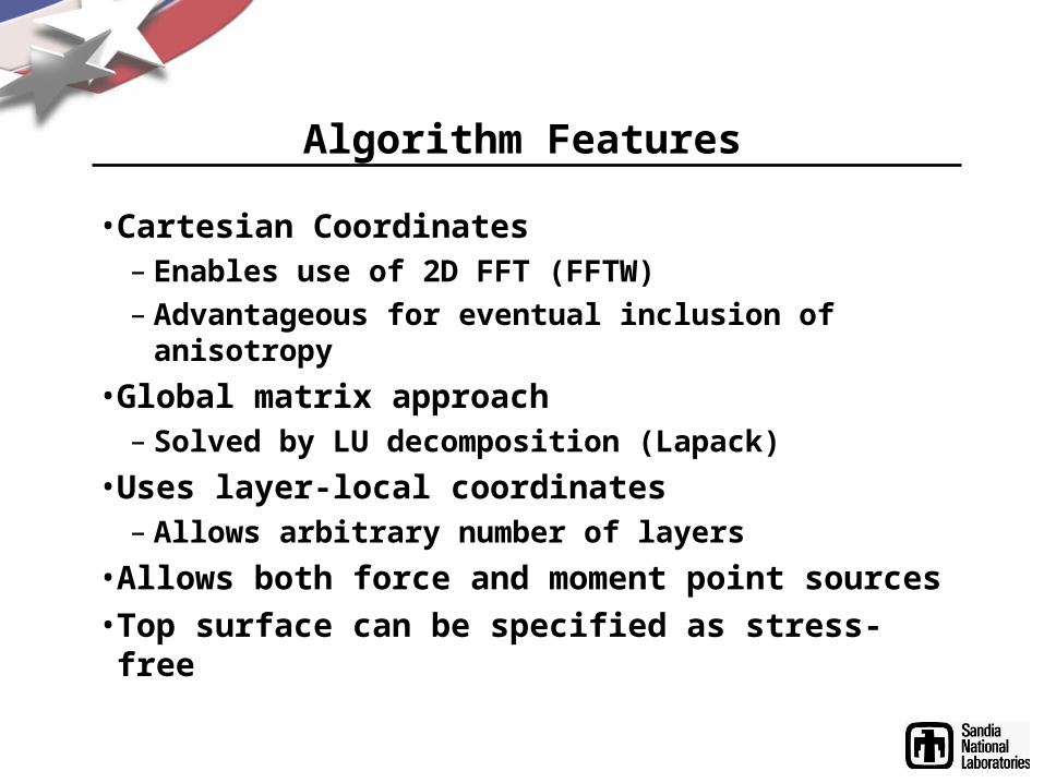
• Cartesian Coordinates– Enables use of 2D FFT (FFTW)
– Advantageous for eventual inclusion of anisotropy
• Global matrix approach– Solved by LU decomposition (Lapack)
• Uses layer-local coordinates– Allows arbitrary number of layers
• Allows both force and moment point sources• Top surface can be specified as stress-free
Algorithm Features

• Variation of material properties limited to 1-D• Thickness of individual layers is limited• Solution is periodic in x, y and t
Algorithm Limitations

• Rectangular spectrum of attenuation mechanisms– Attenuative, dispersive wave propagation
– Characterized by 8 parameters per layer:
Anelastic Geological Layers
, lo, hi, ref
Vp(ref), Qp(ref) Vs(ref), Qs(ref)
High Q medium Low Q medium
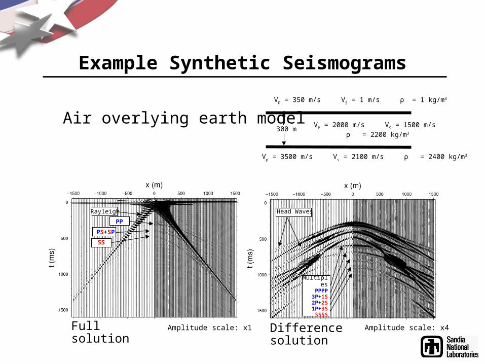
Example Synthetic Seismograms
300 m
VP = 350 m/s V
S = 1 m/s ρ = 1 kg/m3
VP = 2000 m/s V
S = 1500 m/s
ρ = 2200 kg/m3
Vp = 3500 m/s V
s = 2100 m/s ρ = 2400 kg/m3
Rayleigh Head Waves
MultiplesPPPP
3P+1S2P+2S1P+3SSSSS
PP
Amplitude scale: x4
SS
PS+SP
Amplitude scale: x1
Air overlying earth model
Fullsolution
Differencesolution

Problem Geometry
VP = 3500 m/s
VS = 2020 m/s
ρ = 2400 kg/m3
VP = 1500 m/s V
S = 1 m/s ρ = 1000 kg/m3
VP = 350 m/s V
S = 1 m/s ρ = 1 kg/m3
Fluid layer
20 m
d
Sources:Fx, Fz, E,Torque
Receivers: Vx, Vz200 m
Water:
Air:

Problem geometry
Reverberations
Direct ArrivalTop-bed reflectionIntra-bed multiple

Seismic Source Wavelet: Berlage
Berlage waveletcharacteristics:• causal• high-frequency content
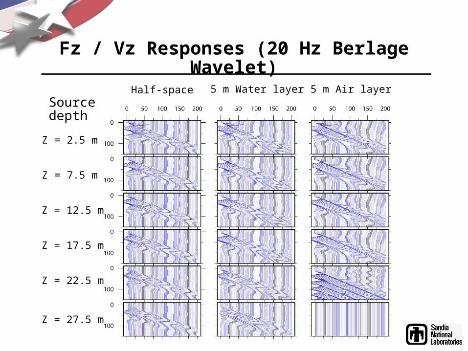
Fz / Vz Responses (20 Hz Berlage Wavelet)
Half-space 5 m Water layer 5 m Air layer
Z = 2.5 m
Z = 7.5 m
Z = 12.5 m
Z = 17.5 m
Z = 22.5 m
Z = 27.5 m
Sourcedepth

Spectra: Fz / Vz (Direct wave subtracted)

Spectra: Fz / Vz (Direct wave subtracted)

Spectra: Fz / Vz (Source in layer)

Spectra: E / Vz (Direct wave subtracted)

Spectra: E / Vz (Direct wave subtracted)
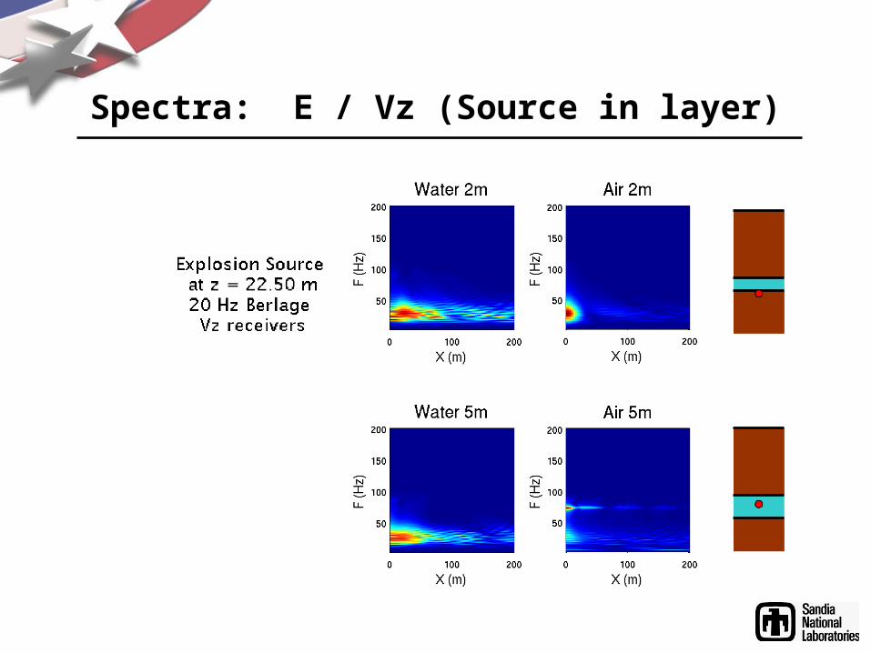
Spectra: E / Vz (Source in layer)

Torque Source Spectra (z = 10 m)
5 m Air layer20 Hz Berlage
Source depthz = 10 m

Fz / Vz Traces (50 Hz Berlage Wavelet)
Half-space 5 m Water layer 5 m Air layer
Z = 2.5 m
Z = 7.5 m
Z = 12.5 m
Z = 17.5 m
Z = 22.5 m
Note: Direct wave subtracted

Spectra: E / Vz (Direct wave subtracted)

Spectra: E / Vz (Direct wave subtracted)

Spectra: E / Vz (Source in layer)
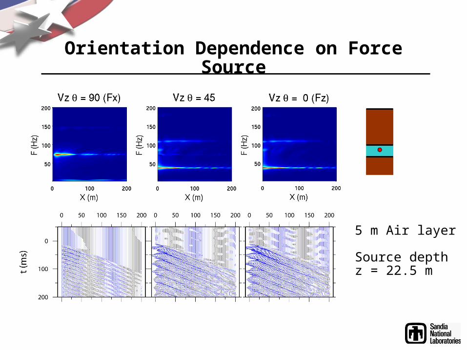
Orientation Dependence on Force Source
5 m Air layer
Source depthz = 22.5 m
• Receiver spectrum is dominated by reverberations in the layer containing the source– No significant generation of reverberations in fluid layer when
source is in overburden • Some sources are more effective than others in generating
reverberations– Explosion sources are efficient at generating reverberations
– Frequency of reverberations from force sources are angle dependent
– Torque sources are inefficient
• Reverberations are stronger in air layers than water layers
• Investigation of magma-filled layers are underway
Conclusions and Ongoing Work

Spectra: Fz / Vz (Direct wave subtracted)

Spectra: Fz / Vz (Direct wave subtracted)

Spectra: Fz / Vz (Source in layer)