numerical simulation and performance investigation of an advanced adsorption desalination cycle
TRANSCRIPT
Desalination 308 (2013) 209–218
Contents lists available at SciVerse ScienceDirect
Desalination
j ourna l homepage: www.e lsev ie r .com/ locate /desa l
Numerical simulation and performance investigation of an advanced adsorptiondesalination cycle
Kyaw Thu a, Anuthosh Chakraborty b, Young-Deuk Kim a, Aung Myat c,Bidyut Baran Saha d, Kim Choon Ng a,c,⁎a Water Desalination and Reuse Center, King Abdullah University of Science and Technology, Thuwal 23955-6900, Saudi Arabiab Department of Mechanical and Aerospace Engineering, Nanyang Technological University, 50 Nanyang Avenue 639798, Singaporec Mechanical Engineering Department, National University of Singapore, 9 Engineering Drive 1 117576, Singapored Mechanical Engineering Department, Kyushu University, 744 Motooka, Nishi-ku, Fukuoka 819-0395, Japan
⁎ Corresponding author at: Mechanical Engineering Dof Singapore, 9 Engineering Drive 1 117576, Singapore. T6779 1459.
E-mail address: [email protected] (K.C. Ng).
0011-9164/$ – see front matter © 2012 Elsevier B.V. Alldoi:10.1016/j.desal.2012.04.021
a b s t r a c t
a r t i c l e i n f oArticle history:Received 31 January 2012Received in revised form 15 April 2012Accepted 18 April 2012Available online 14 May 2012
Keywords:AdsorptionDesalinationWaste heat recoveryHeat and mass recovery
Low temperature waste heat-driven adsorption desalination (AD) cycles offer high potential as one of themost economically viable and environmental-friendly desalination methods. This article presents the devel-opment of an advanced adsorption desalination cycle that employs internal heat recovery between the evap-orator and the condenser, utilizing an encapsulated evaporator–condenser unit for effective heat transfer. Asimulation model has been developed based on the actual sorption characteristics of the adsorbent–adsorbatepair, energy and mass balances applied to the components of the AD cycle. With an integrated design, the tem-perature in the evaporator and the vapor pressurization of the adsorber are raised due to the direct heat recov-ery from the condenser, resulting in the higher water production rates, typically improved by as much as threefolds of the conventional AD cycle. In addition, the integrated design eliminates two pumps, namely, the con-denser cooling water and the chilled water pumps, lowering the overall electricity consumption. The perfor-mance of the cycle is analyzed at assorted heat source and cooling water temperatures, and different cycletimes as well as the transient heat transfer coefficients of the evaporation and condensation.
© 2012 Elsevier B.V. All rights reserved.
Nomenclature
ρ densityepartment, Nael.: +65 651
rights reserv
kg m−3
q"
heat flux W m−2_m
mass flow rate kg s−1γ
flag which governs mode of operation –θ
flag which governs mode of operation –μ
viscosity kg m−1 s−1σ
surface tension N m−1τ
number of cycles per day –A
area m2c
uptake by the adsorbent material kg kg−1c⁎
the equilibrium uptake kg kg−1c0
the limiting uptake kg kg−1COP
the Coefficient of Performance –cp
specific heat capacity J kg−1 K−1Csf
a constant of Rohsenow correlation –Dso
a kinetic constant for the silica gel water system m2 s−1Ea
activation energy of surface diffusion kJ mol−1g
gravitational acceleration m s−2hf
sensible heat kJ kg−1hfg
latent heat kJ kg−1k
the thermal conductivity W m−1 K−1tional University6 2214; fax: +65
ed.
L
Length m M mass kg n number of beds –P
pressure Pa P0 reference pressure Pa PR performance ratio –Q
the total heat or energy J or W Qst isosteric heat of adsorption kJ kg−1r
radius m R Universal gas constant J K−1 mol−1Rp
average radius of silica gel m SDWP specific daily water production m3 t−1 day−1T
temperature K t time s T0 reference temperature K UOverall overall heat transfer coefficient W m−2 K−1v
specific volume m3 kg−1vp
the pore volume cm3 g−1X
concentration mg L−1Subscripts
a adsorbate ads adsorption Brine concentrated brine ch chilled water Cond condenser cw cooling water d distillate(continued on next page)
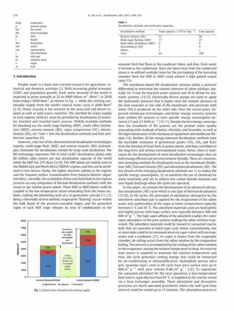
Table 1
210 K. Thu et al. / Desalination 308 (2013) 209–218
Evap
evaporatorFig. 1. Global water demand and existing supply.
Desalination methods and production capacities.
g gaseous phase6 3 −1
hw hot water Desalination method Total capacity (×10 m day ) % by capacity HX heat exchanger Reverse osmosis (RO) 37 59 in inlet Multi-stage flashing (MSF) 17 27 l liquid Multi-effect distillation (MED) 6 9 des desorption Electrodialysis (ED) 2 4 out outlet Others 1 1 reg regeneration Total 63 100 s salt/adsorbentsg
silica gel ss stainless steel v vapor w wall1. Introduction
Potable water is a basic and essential resource for agriculture, in-dustrial and domestic activities [1]. With increasing global economic(GDP) and population growth, fresh water demand of the world isexpected to grow annually at 2% to 6900 billion m3 (Bnm3) in 2030from today's 4500 Bnm3, as shown in Fig. 1, while the existing sus-tainable supply from the earth's natural water cycle is 4200 Bnm3
[2–8]. Water scarcity is the severest in the semi-arid and desert re-gions as well as land scarce countries. The shortfall for water supplyin such regions, hitherto, must be provided by desalination of seawa-ter, brackish and recycled water sources. Widely available methodsfor desalting are the multi-stage flashing (MSF), multi-effect distilla-tion (MED), reverse osmosis (RO), vapor compression (VC), electro-dialysis (ED), etc. Table 1 lists the desalinationmethods and their pro-duction capacities [9].
However, only two of the aforementioned desalination technologiesnamely, multi-stage flash (MSF) and reverse osmosis (RO) technolo-gies, dominate the desalination market for large-scale production. TheRO technology represents 59% of total 14,451 desalination plants with60 million cubic meters per day desalination capacity of the worldwhile the MSF has 27% share [9,10]. The MSF plants are widely used intheMiddle East andNorthAfrica (MENA) regions, and this can be attrib-uted to two factors: firstly, the higher seawater salinity in the regionsand the frequent surface contamination from bacteria blooms (algae/red tides); secondly, the availability of low cost fossil fuels in the regionspresents an easy integration of thermal desalination methods with thesteam or gas turbine power plants. These MSF or MED plants could becoupled to the low temperature steam emanating from the steam tur-bines, making the bottoming cycle of a co-generation concept [11,12].Being a thermally-driven method, evaporative “flashing” occurs withinthe bulk liquid of the pressure-cascaded stages, and the generatedvapor of each MSF stage releases its heat of condensation to the
seawater feed that flows in the condenser tubes, and thus, fresh wateris formed as the condensate. Since the latent heat from the condensedsteam is re-utilized multiple times for the pre-heating of the incomingseawater feed, the MSF or MED could achieve a high gained outputratio [13].
The membrane-based RO desalination systems utilize a pressuredifferential to overcome the osmotic pressure of saline solution, typ-ically 10–15 bar for brackish water systems and 50 to 80 bar for sea-water systems [14,15]. Electrically-driven pumps are used to applythe hydrostatic pressure that is higher than the osmotic pressure tothe feed seawater at one side of the membrane, and permeate withlower TDS is produced on the other side. Over the recent years, im-proved membrane technologies and better energy recovery systemshave yielded RO systems to have specific energy consumption be-tween 2.5 and 3.5 kWhm−3 [16,17]. Despite the lowenergy consump-tion, the drawbacks of RO systems are the product water qualityassociating with residuals of boron, chlorides, and bromides, as well asthe highmaintenance of themechanical equipment andmembrane life-span [18]. Besides, all the energy intensive desalination methods havethe inevitable emissions of greenhouse gasses (CO2, CH4 and N2O)from the burning of fossil fuels at power plants, and they contribute tothe long-term and serious environmental issues. Hence, there is moti-vation for the development of novel desalination technologies that areboth energy efficient and yet environment-friendly. There are, however,new emergingmethods for desalination such as themembrane distilla-tion (MD), forward osmosis (FO) and adsorption desalination (AD). Thekey thrusts of the emerging desalination methods are (i) to reduce thespecific energy consumption, (ii) to minimize the use of chemicals forwater treatment, and (iii) to achieve low carbon dioxide emission andzero liquid discharge when the cycles are operated.
In this paper, we present the development of an advanced adsorp-tion desalination (AD) cycle which is one type of thermal desalination[19,20]. In AD cycles, the principles of adsorption–desorption by theadsorbent–adsorbate pair is applied for the evaporation of the salinewater and condensation of the vapor at lower temperatures typicallybetween 5 °C and 45 °C. The adsorbent materials used are hydrophilicand highly porous with huge surface area typically between 500 and800 m2 g−1. The high vapor affinity of the adsorbent enables the watervapor adsorption on the pore surfaces making the saline solution evap-orated. The adsorbent materials could be housed in vacuumed reactorbeds that are operated in batch-type cycle where concomitantly, oneormore beds could be in communication via vapor valveswith an evap-orator and a condenser [21]. As vapor is drawn from the evaporatorchamber, de-salting occurs from the saline solution by the evaporativeboiling. This process is accompanied by the cooling of the saline solutionin the evaporator causing the solution temperature to drop. An externalheat source is supplied to maintain the solution temperature andthus, the cycle generates cooling energy that could be harnessedfor air-conditioning or dehumidification. Hydrophilic porous silicagels (granular-type) used in AD cycle have pore surface area up to860 m2 g−1 with pore volume 0.48 cm3 g−1 [22]. To regeneratethe saturated adsorbent for the next operation, a low-temperatureheat source, typically less than 85 °C, is supplied to the reactor vesselvia a heat exchanger assembly. These adsorption and desorptionprocesses are batch-operated procedures where the half cycle timeinterval could be varied up to 15 minutes. The adsorption process is
211K. Thu et al. / Desalination 308 (2013) 209–218
an exothermic process and thus the adsorbent in reactor vesselhas to be cooled so as to sustain the vapor uptake by the silicagels. A cooling tower water circuit is used to reject the heat ofadsorption.
We exploit the higher uptake of silica gels by subjecting them to ahigher vapor pressure in the adsorption cycle. An increase in thevapor uptake can be easily realized from their isotherm characteris-tics. The novelty of this design is that such a pressurization effect isreadily achieved by the recovery of latent heat of condensation (atcondenser) into the evaporator unit which is built into the condenser.The evaporative cooling (as initiated by the adsorption process)is directly dumped into the condenser tubes which aided thecondensation. No pump is needed to achieve the heat transfer betweenthem and any excess heat from condenser can be rejected by a heatexchanger, which is cooled by a cooling tower. The present articlediscusses the development of the advanced AD cycle by a detailednumerical model. These adsorption, heat and mass transfer processesof the cycle are realistically captured with the sorption characteristicsof adsorbent, energy and mass balances of the working fluids. Thecycle performance is analyzed at assorted heat source and coolanttemperatures, and the useful outputs are described by parameterssuch as the specific daily water production (SDWP) and the perfor-mance ratio (PR).
2. Description of the advanced AD cycle
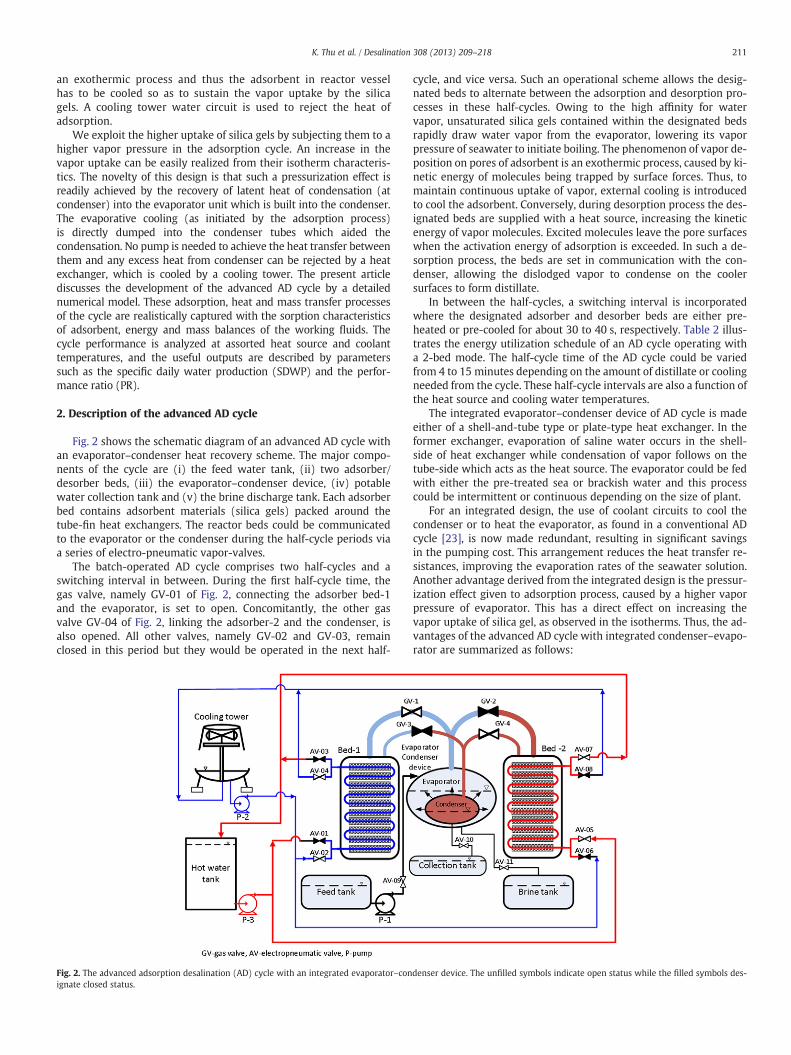
Fig. 2 shows the schematic diagram of an advanced AD cycle withan evaporator–condenser heat recovery scheme. The major compo-nents of the cycle are (i) the feed water tank, (ii) two adsorber/desorber beds, (iii) the evaporator–condenser device, (iv) potablewater collection tank and (v) the brine discharge tank. Each adsorberbed contains adsorbent materials (silica gels) packed around thetube-fin heat exchangers. The reactor beds could be communicatedto the evaporator or the condenser during the half-cycle periods viaa series of electro-pneumatic vapor-valves.
The batch-operated AD cycle comprises two half-cycles and aswitching interval in between. During the first half-cycle time, thegas valve, namely GV-01 of Fig. 2, connecting the adsorber bed-1and the evaporator, is set to open. Concomitantly, the other gasvalve GV-04 of Fig. 2, linking the adsorber-2 and the condenser, isalso opened. All other valves, namely GV-02 and GV-03, remainclosed in this period but they would be operated in the next half-
Fig. 2. The advanced adsorption desalination (AD) cycle with an integrated evaporator–conignate closed status.
cycle, and vice versa. Such an operational scheme allows the desig-nated beds to alternate between the adsorption and desorption pro-cesses in these half-cycles. Owing to the high affinity for watervapor, unsaturated silica gels contained within the designated bedsrapidly draw water vapor from the evaporator, lowering its vaporpressure of seawater to initiate boiling. The phenomenon of vapor de-position on pores of adsorbent is an exothermic process, caused by ki-netic energy of molecules being trapped by surface forces. Thus, tomaintain continuous uptake of vapor, external cooling is introducedto cool the adsorbent. Conversely, during desorption process the des-ignated beds are supplied with a heat source, increasing the kineticenergy of vapor molecules. Excited molecules leave the pore surfaceswhen the activation energy of adsorption is exceeded. In such a de-sorption process, the beds are set in communication with the con-denser, allowing the dislodged vapor to condense on the coolersurfaces to form distillate.
In between the half-cycles, a switching interval is incorporatedwhere the designated adsorber and desorber beds are either pre-heated or pre-cooled for about 30 to 40 s, respectively. Table 2 illus-trates the energy utilization schedule of an AD cycle operating witha 2-bed mode. The half-cycle time of the AD cycle could be variedfrom 4 to 15 minutes depending on the amount of distillate or coolingneeded from the cycle. These half-cycle intervals are also a function ofthe heat source and cooling water temperatures.
The integrated evaporator–condenser device of AD cycle is madeeither of a shell-and-tube type or plate-type heat exchanger. In theformer exchanger, evaporation of saline water occurs in the shell-side of heat exchanger while condensation of vapor follows on thetube-side which acts as the heat source. The evaporator could be fedwith either the pre-treated sea or brackish water and this processcould be intermittent or continuous depending on the size of plant.
For an integrated design, the use of coolant circuits to cool thecondenser or to heat the evaporator, as found in a conventional ADcycle [23], is now made redundant, resulting in significant savingsin the pumping cost. This arrangement reduces the heat transfer re-sistances, improving the evaporation rates of the seawater solution.Another advantage derived from the integrated design is the pressur-ization effect given to adsorption process, caused by a higher vaporpressure of evaporator. This has a direct effect on increasing thevapor uptake of silica gel, as observed in the isotherms. Thus, the ad-vantages of the advanced AD cycle with integrated condenser–evapo-rator are summarized as follows:
denser device. The unfilled symbols indicate open status while the filled symbols des-

Table 2Energy utilization schedule of an AD cycle with 2-bed operation mode.
Adsorber Cycle-1 SW-1 Cycle-2 SW-2
BED-1 Ads Pre-heat Des Pre-coolBED-2 Des Pre-cool Ads Pre-heat
Ads: adsorption, Des: desorption, Pre-heat: preheating, Pre-cool: precooling.
Table 4
212 K. Thu et al. / Desalination 308 (2013) 209–218
i) a reduction in the parasitic electrical power consumption withthe elimination of pumps for chilled and cooling water circuits,
ii) an improvement in the adsorption capacity of silica gel due tothe pressurization effect of evaporator,
iii) a lowering of the effective condensation temperature in con-denser and this tends to desorb more vapor during the desorp-tion process, and
iv) improvement in heat transfer resistances enables the AD cycleto operate at even lower heat source temperatures, typically 50to 80 °C.
3. Mathematical modeling
A mathematical model on an advanced AD cycle that employs anintegrated evaporator–condenser design for the internal heat recov-ery process was developed to access the performance of the cycle. Iso-therm and kinetics properties of the silica gel–water pair are used topredict the uptake of the water vapor by the silica gels at specific tem-perature and pressure conditions. Mass and energy balances of thecomponents involved in the cycle are further employed to evaluatethe model. Type A++ silica gel was used as the adsorbent andTable 3 gives the physical properties the selected silica gel. The over-all mass balance of the cycle is given by
dMs;Evap
dt¼ _ms;in− _md;Cond− _mBrine; ð1Þ
Here, Ms,Evap is the amount of seawater in the evaporator, _ms;in isthe mass flow rate of feed sea water, and _md;Cond and _mBrine are themass flow rates of potable water extracted from the condenser andconcentrated brine rejected from the evaporator, respectively. Thefeed seawater is intermittently pumped into the evaporator depend-ing on the amount and level of seawater to sustain the effective evap-oration while the concentrated brine is discharged once theconcentration of the saline water in the evaporator reaches the pre-determined limit which is determined based on the recovery ratio.The mass and salt balances for the evaporator of the AD cycle aregiven as
dMs;Evap
dt¼ θ _ms;in
zfflfflffl}|fflfflffl{Feed
− γ _mBrine
zfflfflfflffl}|fflfflfflffl{Brine rejection
− ndcadsdt
Msg
zfflfflfflfflfflfflfflfflffl}|fflfflfflfflfflfflfflfflffl{Vapour uptake by adsorption processes
; ð2Þ
Ms;EvapdXs;Evap
dt¼ θXs;in _ms;in−γXs;Evap _mBrine−nXD
dcadsdt
Msg; ð3Þ
Table 3Physical properties of Type A++ silica gel.
Property Value
Pore size(nm) 0.8–7.5Porous volume(cm3 g−1) 0.476Surface area(m2 g−1) 863.6Average pore diameter (nm) 2.2Apparent density (kg m−3) 700pH 4.0Specific heat capacity (kJ kg−1 k−1) 0.921Thermal conductivity (W m−1 k−1) 0.198
where Xs,in and Xs,Evap are the concentration of the feed and seawaterin the evaporator, XD is the concentration of the vapor while thecoefficients θ andγ are the flags for the feed water and brine dischargewhose values are 1 whenever the feed is supplied or brine isdischarged from the system. The value of n indicates the number ofadsorber beds performing adsorption process. The values of theseoperational flags are listed in Table 4. In this simulation, we adoptedan AD cycle with four physical adsorber beds operating as a 2-bedmachine where each pair of two beds performs adsorption processand the other pair as desorption process. This configuration isselected in order to conduct the performance comparison with theexperimental data taken from a 4-bed AD cycle operating at 2-bedmode. It is noted that the same amount of adsorbent inventory asthe experimental plant is used in the simulation, and thus the valueof n is 2.
In AD cycles, the evaporation of seawater is attributed to the up-take of the water vapor by the adsorbent materials and thermal ener-gy recovered from the condensation is used to maintain theevaporation process at certain temperature level. The energy balanceof the evaporator is written as
Ms;Evapcp;s TEvap;Xs;Evap
� �þMHX;Evap cp;HX
h idTEvap
dt¼ θ hf TEvap;Xs;Evap
� �_ms;in
−n hfg TEvap
� � dcadsdt
Msg þ UEC A TCond−TEvap
� �−γ hf TEvap;Xs;Evap
� �_mBrine;
ð4Þ
where MHX,Evap is the total mass of the evaporator, Msg is the mass ofsilica gel, _mBrine is the mass flow rate of brine discharge, and cads de-notes water vapor uptake by the adsorbent. The first term in theright hand side of Eq. (4) represents the sensible heat by the suppliedfeed seawater, the second term stands for the latent heat removal bythe uptake of adsorbent, and the third and fourth terms denote theenergy for the evaporation through heat recovery from the condensa-tion process and the sensible heat removal by the brine discharge. Thespecific heat (cp,s) and enthalpy (hf) of seawater are calculated asfunctions of temperature, pressure and salinity [24].
As the evaporated seawater is associated onto the solid adsorbentin the adsorber bed by the flow of external cooling fluid duringadsorption period, while the desorbed water vapor is dissociatedfrom the solid adsorbent by the flow of heating fluid duringdesorption period, thermal energy is exchanged between cooling/heating fluid and the adsorption/desorption bed. The energy balanceequation of the adsorber bed connected with the evaporator as wellas that for the desorber bed commuting with the condenser is givenby
Msgcp;sg þMHXcp;HX þMabecp;ah idTads=des
dt¼ �n:Q st Msg
dcads=desdt
�_mcw=hw cp Tcw=hw
� �Tcw=hw;in−Tcw=hw;out
� � ;
ð5Þ
Values of the indicators for changing the operation mode of the AD cycle.
Mode Parameter 4-Bed cycle operating at 2-bed mode
Operation n 2θ 1 (Charging sea water)
0 (Otherwise)γ 1 (Brine discharge)
0 (Otherwise)Switching n 2
θ 1 (Charging sea water)0 (Otherwise)
γ 1 (Brine discharge)0 (Otherwise)
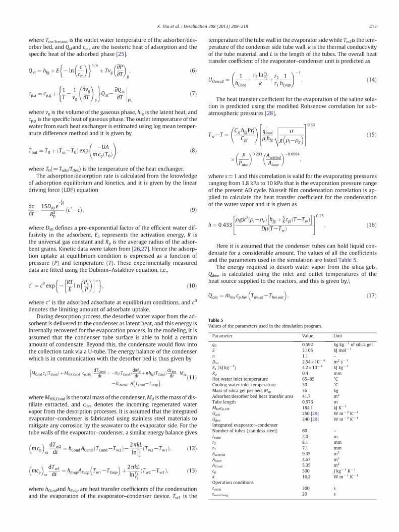
Table 5Values of the parameters used in the simulation program.
Parameter Value Unit
q0 0.592 kg kg−1 of silica gelE 3.105 kJ mol−1
n 1.1 –
Dso 2.54×10⁻⁴ m2 s−1
Ea (kJ kg−1) 4.2×10⁻⁴ kJ kg−1
Rp 0.4 mmHot water inlet temperature 65–85 °CCooling water inlet temperature 30 °CMass of silica gel per bed, Msg 36 kgAdsorber/desorber bed heat transfer area 41.7 m2
Tube length 0.576 mMHXcp,HX 184.1 kJ K−1
Uads 250 [29] W m−2 K−1
Udes 240 [29] W m−2 K−1
Integrated evaporator–condenserNumber of tubes (stainless steel) 60 –
Ltube 2.0 mr2 8.1 mmr1 7.1 mmAwetted 9.35 m2
Abase 4.67 m2
ACond 5.35 m2
cp 500 J kg−1 K−1
k 16.2 W m−1 K−1
Operation conditionstcycle 300 stswitching 20 s
213K. Thu et al. / Desalination 308 (2013) 209–218
where Tcw/hw,out is the outlet water temperature of the adsorber/des-orber bed, and Qstand cp,a are the isosteric heat of adsorption and thespecific heat of the adsorbed phase [25].
Q st ¼ hfg þ E − lnccm
� �� �1=nþ Tvg
∂P∂T
� �g; ð6Þ
cp;a ¼ cp;g þ1T− 1
vg
∂vg∂T
!P
( )Q st−
∂Q st
∂TP;
ð7Þ
where vg is the volume of the gaseous phase, hfg is the latent heat, andcp,g is the specific heat of gaseous phase. The outlet temperature of thewater from each heat exchanger is estimated using log mean temper-ature difference method and it is given by
Tout ¼ T0 þ T in−T0ð Þ exp −UA_mcp T0ð Þ
!; ð8Þ
where T0(=Tads/Tdes) is the temperature of the heat exchanger.The adsorption/desorption rate is calculated from the knowledge
of adsorption equilibrium and kinetics, and it is given by the lineardriving force (LDF) equation
dcdt
¼ 15Ds0 e−EaRT
R2p
c�−c �
; ð9Þ
where Ds0 defines a pre-exponential factor of the efficient water dif-fusivity in the adsorbent, Ea represents the activation energy, R isthe universal gas constant and Rp is the average radius of the adsor-bent grains. Kinetic data were taken from [26,27]. Hence the adsorp-tion uptake at equilibrium condition is expressed as a function ofpressure (P) and temperature (T). These experimentally measureddata are fitted using the Dubinin–Astakhov equation, i.e.,
c� ¼ c0 exp − RTE
l nPs
P
� �� n� �; ð10Þ
where c* is the adsorbed adsorbate at equilibrium conditions, and c0
denotes the limiting amount of adsorbate uptake.During desorption process, the desorbed water vapor from the ad-
sorbent is delivered to the condenser as latent heat, and this energy isinternally recovered for the evaporation process. In the modeling, it isassumed that the condenser tube surface is able to hold a certainamount of condensate. Beyond this, the condensate would flow intothe collection tank via a U-tube. The energy balance of the condenserwhich is in communication with the desorber bed is thus given by
MCond cp TCondð Þ þMHX;Cond cp;HXh idTCond
dt¼ −hf TCondð ÞdMd
dtþ nhfg TCondð Þdcdes
dtMsg
−UOverall A TCond−TEvap
� �;
ð11Þ
whereMHX,Cond is the total mass of the condenser,Md is themass of dis-tillate extracted, and cdes denotes the incoming regenerated watervapor from the desorption processes. It is assumed that the integratedevaporator–condenser is fabricated using stainless steel materials tomitigate any corrosion by the seawater to the evaporator side. For thetube walls of the evaporator–condenser, a similar energy balance gives
mcp� �
ss
dTw2
dt¼ hCondACond TCond−Tw2ð Þ−2πkL
ln r1r2
Tw2−Tw1ð Þ; ð12Þ
mcp� �
ss
dTw1
dt¼ hEvapAEvap Tw1−TEvap
� �þ 2πkL
ln r1r2
Tw2−Tw1ð Þ; ð13Þ
where hCondand hEvap are heat transfer coefficients of the condensationand the evaporation of the evaporator–condenser device. Tw1 is the
temperature of the tubewall in the evaporator sidewhile Tw2is the tem-perature of the condenser side tube wall, k is the thermal conductivityof the tube material, and L is the length of the tubes. The overall heattransfer coefficient of the evaporator–condenser unit is predicted as
UOverall ¼1
hCondþr2 ln
r1r2
kþ r2r1
1hEvap
!−1
; ð14Þ
The heat transfer coefficient for the evaporation of the saline solu-tion is predicted using the modified Rohsenow correlation for sub-atmospheric pressures [28],
Tw−T ¼ Csf hfgPrsl
Cpf
!q}loadμ lhfg
ffiffiffiffiffiffiffiffiffiffiffiffiffiffiffiffiffiffiffiffiffiffiσ
g ρl−ρg
� �vuut264
3750:33
� PPatm
� �0:293 Awetted
Abase
� ��0:0984;
ð15Þ
where s=1 and this correlation is valid for the evaporating pressuresranging from 1.8 kPa to 10 kPa that is the evaporation pressure rangeof the present AD cycle. Nusselt film condensation correlation is ap-plied to calculate the heat transfer coefficient for the condensationof the water vapor and it is given as
h ¼ 0:433ρlgk
3 ρl−ρvð Þ hfg þ 38 cpl T−Twð Þ
h iDμ T−Twð Þ
24
350:25
; ð16Þ
Here it is assumed that the condenser tubes can hold liquid con-densate for a considerable amount. The values of all the coefficientsand the parameters used in the simulation are listed Table 5.
The energy required to desorb water vapor from the silica gels,Qdes, is calculated using the inlet and outlet temperatures of theheat source supplied to the reactors, and this is given by,\
Qdes ¼ _mhw cp;hw Thw;in−Thw;out
� �; ð17Þ
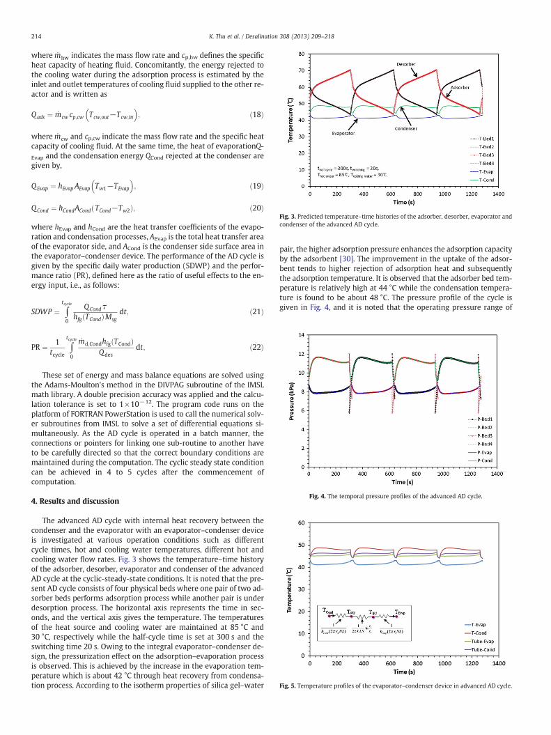
Fig. 3. Predicted temperature–time histories of the adsorber, desorber, evaporator andcondenser of the advanced AD cycle.
Fig. 4. The temporal pressure profiles of the advanced AD cycle.
Fig. 5. Temperature profiles of the evaporator–condenser device in advanced AD cycle.
214 K. Thu et al. / Desalination 308 (2013) 209–218
where _mhw indicates the mass flow rate and cp,hw defines the specificheat capacity of heating fluid. Concomitantly, the energy rejected tothe cooling water during the adsorption process is estimated by theinlet and outlet temperatures of cooling fluid supplied to the other re-actor and is written as
Qads ¼ _mcw cp;cw Tcw;out−Tcw;in
� �; ð18Þ
where _mcw and cp,cw indicate the mass flow rate and the specific heatcapacity of cooling fluid. At the same time, the heat of evaporationQ-Evap and the condensation energy QCond rejected at the condenser aregiven by,
QEvap ¼ hEvap AEvap Tw1−TEvap
� �; ð19Þ
QCond ¼ hCondACond TCond−Tw2ð Þ; ð20Þ
where hEvap and hCond are the heat transfer coefficients of the evapo-ration and condensation processes, AEvap is the total heat transfer areaof the evaporator side, and ACond is the condenser side surface area inthe evaporator–condenser device. The performance of the AD cycle isgiven by the specific daily water production (SDWP) and the perfor-mance ratio (PR), defined here as the ratio of useful effects to the en-ergy input, i.e., as follows:
SDWP ¼ ∫tcycle
0
QCond τhfg TCondð ÞMsg
dt; ð21Þ
PR ¼ 1tcycle
∫tcycle
0
_md;Condhfg TCondð ÞQdes
dt; ð22Þ
These set of energy and mass balance equations are solved usingthe Adams-Moulton's method in the DIVPAG subroutine of the IMSLmath library. A double precision accuracy was applied and the calcu-lation tolerance is set to 1×10⁻¹². The program code runs on theplatform of FORTRAN PowerStation is used to call the numerical solv-er subroutines from IMSL to solve a set of differential equations si-multaneously. As the AD cycle is operated in a batch manner, theconnections or pointers for linking one sub-routine to another haveto be carefully directed so that the correct boundary conditions aremaintained during the computation. The cyclic steady state conditioncan be achieved in 4 to 5 cycles after the commencement ofcomputation.
4. Results and discussion
The advanced AD cycle with internal heat recovery between thecondenser and the evaporator with an evaporator–condenser deviceis investigated at various operation conditions such as differentcycle times, hot and cooling water temperatures, different hot andcooling water flow rates. Fig. 3 shows the temperature–time historyof the adsorber, desorber, evaporator and condenser of the advancedAD cycle at the cyclic-steady-state conditions. It is noted that the pre-sent AD cycle consists of four physical beds where one pair of two ad-sorber beds performs adsorption process while another pair is underdesorption process. The horizontal axis represents the time in sec-onds, and the vertical axis gives the temperature. The temperaturesof the heat source and cooling water are maintained at 85 °C and30 °C, respectively while the half-cycle time is set at 300 s and theswitching time 20 s. Owing to the integral evaporator–condenser de-sign, the pressurization effect on the adsorption–evaporation processis observed. This is achieved by the increase in the evaporation tem-perature which is about 42 °C through heat recovery from condensa-tion process. According to the isotherm properties of silica gel–water
pair, the higher adsorption pressure enhances the adsorption capacityby the adsorbent [30]. The improvement in the uptake of the adsor-bent tends to higher rejection of adsorption heat and subsequentlythe adsorption temperature. It is observed that the adsorber bed tem-perature is relatively high at 44 °C while the condensation tempera-ture is found to be about 48 °C. The pressure profile of the cycle isgiven in Fig. 4, and it is noted that the operating pressure range of

Table 6The performance ratio (PR) of the advanced AD cycle.
Tcw(°C)
Hot water inlet temperature (°C)
85 80 75 70 65 60 55 50
25 0.698 0.702 0.704 0.705 0.706 0.705 0.703 0.70030 0.706 0.708 0.709 0.710 0.710 0.708 0.705 0.69935 0.707 0.709 0.710 0.710 0.709 0.707 0.702 0.694
215K. Thu et al. / Desalination 308 (2013) 209–218
the advanced AD cycle is elevated to 7–12 kPa in contrast with theconventional cycle where the pressure ranges from 3 to 7 kPa. Theperformance of the evaporator–condenser device is presented inFig. 5 where the maximum temperature difference between the evap-orator and the condenser wall is observed to be 1.3 °C.
To further understand the processes involved in the advanced ADcycle, temperature–pressure–concentration diagram (Dühring Dia-gram) is applied to track the performance of the cycle. Fig. 6 exhibitsthe Dühring diagram of the advanced AD cycle where it is comparedwith a conventional AD cycle. It is noted that the advanced cycle oper-ates at elevated pressure regions i.e., 7–12 kPa. The adsorbent uptakein the advanced cycle reaches up to 40% of the dry mass of the adsor-bent while the vapor in the adsorbent material is about 25% duringdesorption cycle. The net uptake by the adsorbent for a completecycle is about 15%. In a conventional AD cycle, separate evaporatorand condenser units are used for the evaporation of seawater andcondensation of the desorbed water with no heat recovery betweenthem. The maximum uptake by the adsorbent in such cycle is about18% whereas the regeneration cycle can reach to 7% of the dry massgiving the net uptake of 11%. Thus, the improvement in the uptakeby the silica gels per cycle (adsorption–desorption) in advancedcycle is 36.4% as compared to the conventional cycle for the sameheat source and cooling water temperatures. It is noted that thehalf-cycle time of the advanced cycle is set at 300 s whereas that ofthe conventional cycle is about 600 s meaning that the advanced ADcycle can achieve almost twice as much the number of cycles per
Fig. 6. Comparison of the advanced and conventional AD cycles on a P–T–C diagram.
Fig. 7. Water production rate of the advanced AD cycle.
day as a conventional cycle. Therefore, the quantum jump in the spe-cific daily water production (SDWP) is expected in the advanced ADcycle since the net uptake in advanced cycle improved by 36% inhalf the cycle time required by a conventional cycle.
The transient water production rate of the advanced AD cycle interms of liters per minute is given in Fig. 7 where the equivalent spe-cific daily water production (SDWP) of the cycle is found to be around26 m3 per tonne of silica gel per day. The water production rate by theadvanced cycle is almost three times higher than the yield from a con-ventional AD cycle. The quantum rise in the SDWP by the advancedAD cycle is attributed to two factors, namely, (i) the improvementin the net adsorption capacity of the silica gels, up to 40% of the drymass, owing to the pressurization effect during the adsorption pro-cess and (ii) a lowering of the effective condensation temperaturein the condenser due to lesser resistance in heat transfer, and thistends to desorb more vapor out of the desorber during the desorptionprocess. It is noted that the advanced AD cycle produces only potablewater compromising the cooling power production in contrast withthe conventional AD cycle where simultaneous production of coolingand potable water is realized from the evaporator and the condenser,respectively [31]. With quantum jump in the water production andthe elimination of two high-powered pumps for chilled water circuitin the evaporator and cooling water circuit in the condenser, the spe-cific energy consumption of an advanced AD cycle is found to be1.38 kWh m−3 while operating on waste heat from processes orsolar energy [32,33].
The performance ratio (PR) of the advanced AD cycle is presentedin Table 6. It is noted that the variation in the PR value for differentoperating conditions is relatively insignificant, and the average PRvalue is recorded around 0.7.
The performance of the evaporator–condenser device implemen-ted in the advanced AD cycle is also analyzed in terms of the overallheat transfer coefficient. The overall heat transfer coefficient of theevaporator–condenser unit is evaluated using Modified Rohsenowcorrelation for sub-atmospheric conditions for evaporation and Nus-selt film correlation for condensation. Thermal resistance imposedby the stainless steel tubes is also accounted for. The overall heattransfer coefficient (U) of the evaporator–condenser device is
Fig. 8. Overall heat transfer coefficient of the evaporator–condenser device.
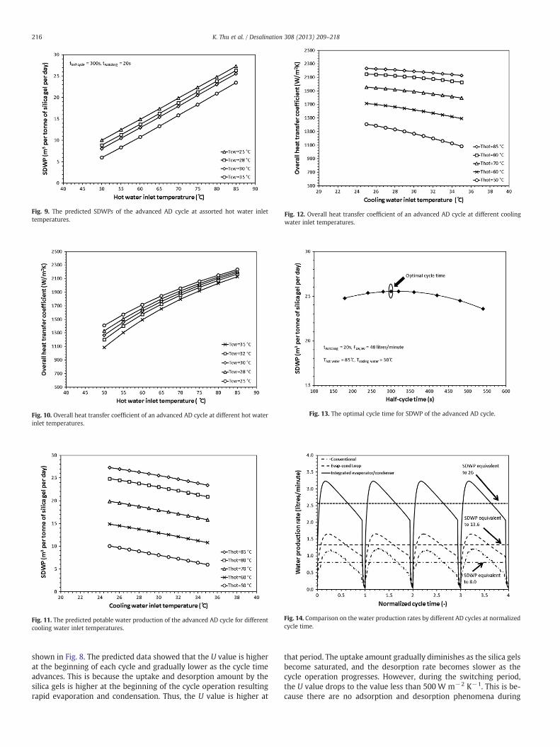
Fig. 9. The predicted SDWPs of the advanced AD cycle at assorted hot water inlettemperatures.
Fig. 10. Overall heat transfer coefficient of an advanced AD cycle at different hot waterinlet temperatures.
ig. 12. Overall heat transfer coefficient of an advanced AD cycle at different coolingater inlet temperatures.
Fig. 13. The optimal cycle time for SDWP of the advanced AD cycle.
Fig. 11. The predicted potable water production of the advanced AD cycle for differentcooling water inlet temperatures.
Fig. 14. Comparison on the water production rates by different AD cycles at normalizedcycle time.
216 K. Thu et al. / Desalination 308 (2013) 209–218
shown in Fig. 8. The predicted data showed that the U value is higherat the beginning of each cycle and gradually lower as the cycle timeadvances. This is because the uptake and desorption amount by thesilica gels is higher at the beginning of the cycle operation resultingrapid evaporation and condensation. Thus, the U value is higher at
Fw
that period. The uptake amount gradually diminishes as the silica gelsbecome saturated, and the desorption rate becomes slower as thecycle operation progresses. However, during the switching period,the U value drops to the value less than 500 W m−2 K−1. This is be-cause there are no adsorption and desorption phenomena during

217K. Thu et al. / Desalination 308 (2013) 209–218
this period, and the resulted small value of U is due to the exchange ofheat between the thermal masses of the evaporator and the condens-er. The cycle average overall heat transfer coefficient (UOverall) isfound to be about 2300 W m−2 K−1 which is quite a good valueacross the vapor condensing in the condenser to the vapor leavingthe saline solution falling over the surface of evaporator tubes.
A parametric analysis on the advanced AD cycle has been con-ducted to study the performance of the cycle at various operatingconditions such as different cycle times, and different hot and coolingwater inlet temperatures to the adsorber beds.
Figs. 9 and 10 represent the specific daily water production(SDWP) and overall heat transfer coefficient (U) of the advanced ADcycle for assorted regeneration temperatures from 50 °C to 85 °C.The results show that the water production rate of the advancedcycle linearly varies with the hot water temperature. This is due tothe better regeneration process for higher hot water temperatures.The results correspondingly exhibit that the overall heat transfer co-efficient increases with the increase in the hot water temperature. Itis noted that the changes in UOverall values at lower hot water inlettemperatures are relatively significant as compared that at higherhot water inlet temperatures. Again, the higher regeneration temper-ature plays a significant role in AD cycles at which the adsorbent de-sorbs effectively and subsequently adsorbs larger amount of watervapor improving the mass transfer traffic between the evaporator–adsorber and desorber–condenser. Thus, rapid condensation ofhigher-temperature water vapor contributes to higher overall heattransfer coefficient of the evaporator–condenser device.
The effect of the cooling water temperature to the adsorber on theperformance of the advanced AD cycle is further investigated. Thetemperature range between 25 °C and 35 °C is selected as this is apractical cooling water temperature range readily available using aconventional cooling tower. The effect of the cooling water tempera-ture on the cycle is investigated at assorted hot water inlet tempera-tures between 50 °C and 85 °C. The performance of the cycle in termsof SDWP is presented in Fig. 11 where the results indicate that thecycle performs more efficiently at lower cooling water temperaturesgiving higher SDWP. As the cooling water temperature increases,the SDWP of the cycle becomes lower. This phenomenon can be at-tributed to the isotherm behavior of the silica gel–water pair wherethe lower-temperature adsorption environment promotes higher up-take capacity by the adsorbent materials.
The effect of cooling water inlet temperature on the overall heattransfer of the evaporator–condenser device is shown in Fig. 12where it highlights significant depreciation in UOverall at lower hotwater inlet temperatures.
The effect of the operation cycle time on the specific daily waterproduction (SDWP) of the cycle at a fixed hot water temperature(85 °C) is presented in Fig. 13. It is noted that the optimal half-cycletime for the advanced AD cycle is 300 s, and this is shorter by 50%when compared to the conventional AD cycle at the same heat sourcetemperature [34]. The shorter cycle time leads to higher water pro-duction yield with increasing numbers of operating cycles per day.
Comparison on the water production rates by different adsorptioncycles at normalized cycle time and same operating conditions(Thot=85 °C and Tcw=30 °C) is given in Fig. 14. A conventional ADcycle and an AD cycle with heat recovery between condenser and evap-orator using an evaporator–condenser heat recovery circuit are selectedfor the comparison [35–37]. It is noted that experimental data for theaforementioned cycles are used here. The results show that the ad-vanced AD cycle can produce potablewater up to three-folds of the con-ventional cycle while it produces twice that of the AD cycle withevaporator–condenser heat recovery circuit for the same adsorbent in-ventory. Another significant advantage of the advanced cycle is that itcan be operational at hot water inlet temperatures as low as 50 °Cwhile a conventional cycle is unable to do so at such low temperatures.Moreover, this kind of low-grade regeneration temperature is readily
available from the solar thermal sources or waste heat from industrialprocesses. The specific daily water production (SDWP) at 50 °C hotwater inlet temperature is found to be about 8.1 m3 day−1, and it iscomparable with that of the conventional cycle even at this low heatsource temperature.
5. Conclusions
We have successfully modeled and predicted the performance ofan advanced adsorption desalination cycle with condenser–evapora-tor heat recovery scheme. The modeling techniques incorporated re-alistic isotherms and kinetics, heat and mass transfer resistances inthe solid–vapor uptake, the evaporative boiling and condensationprocesses. The cycle performances are examined for assorted heatsource and cooling water temperatures.
For the same adsorbent inventory in the cycle, the advanced cycleshows a higher water vapor uptake over the conventional cycle andsuch improvements are clearly observed when the states are plottedon a P–T–C state diagram. Translated into water production capacity,the specific water production yield improves remarkably: varyingfrom 8.1 m3 to 26 m3 at the corresponding heat source temperaturesof 50 °C to 85 °C, respectively. Owing to the integrated design, theoverall heat transfer coefficient of the integrated condenser and evap-orator is found to be higher, typically around 2300 Wm−2 K−1. Usingonly low temperature waste heat as thermal energy input, the specificelectricity consumption of the advanced cycle is about 1.38 kWhm−3, and this is only twice that of the thermodynamic limit neededfor desalination of seawater.
References
[1] http://www.un.org/waterforlifedecade/background.shtml.[2] www.2030waterresourcesgroup.com/water_full/.[3] Jim S. Wallace, Peter J. Gregory, Water resources and their use in food production
systems, Aquat. Sci. 64 (2002) 363–375.[4] P. Pinstrup-Andersen, R. Pandya-Lorch, M.W. Rosegrant, The World Food Situa-
tion: Recent Developments, Emerging Issues, and Long-term Prospects, IFPRI,Washington D.C., 1997
[5] V. Frenkel, Desalination methods, technology and economics, Desalination Con-ference Santa Barbara, CA, USA, 2004.
[6] http://webworld.unesco.org/water/ihp/db/shiklomanov/summary/html/summary.html#5.%20Water.
[7] Semih Otles, Serkan Serkan Otles, Desalination techniques, Electron. J. EnvironAgric. Food. Chem. 4 (2004) 963–969.
[8] Paul Alois, Global Water Crisis Overview, http://www.arlingtoninstitute.org/wbp/global-water-crisis/441#2007.
[9] GWI DesalData/IDA, 21st GWI/International Desalination Association WorldwideDesalting Plant Inventory, Desalination in 2008, Global Market snapshot, 2008.
[10] Lisa Henthorne, The Current State of Desalination, http://www.idadesal.org/PDF/the%20current%20state%20of%20desalination%20remarks%20nov%2009%20by%20lisa%20henthorne.pdf.
[11] M.A. Darwish, N.M. Al-Najem, Energy consumption by multi-stage flash and re-verse osmosis desalters, Appl. Therm. Eng. 20 (2000) 399–416.
[12] Masahiro Murakami, Managing Water for Peace in the Middle East: AlternativeStrategies, United Nations Univ., 1995
[13] K.S. Spiegler, Y.M. El-Sayed, A Desalination Primer, Balaban Desalination Publica-tions, Santa Maria Imbaro, Italy, 1994.
[14] O.K. Buros, The ABCs of Desalting, Second Ed, International Desalination Associa-tion, Topsfield, Mass, 2000.
[15] James E. Miller, Review of Water Resources and Desalination Technologies,http://prod.sandia.gov/techlib/access-control.cgi/2003/030800.pdf2003.
[16] John MacHarg, Thomas F. Seacord, Bradley Sessions, ADC baseline tests revealtrends in membrane performance, Desalin. Water Reuse 18 (2008) 30–39.
[17] M. A1-Shammiri, M. A1-Dawas, Maximum recovery from seawater reverse osmo-sis plants in Kuwait, Desalination 110 (1997) 37–48.
[18] Nikolay Voutchkov, Advances in seawater desalination technology, Water Condi-tioning Purif 49 (2007).
[19] Kim Choon Ng, Bidyut Baran Saha, Anutosh Chakraborty, Shigeru Koyama, Ad-sorption desalination quenches global thirst, Heat Transfer Eng. 29 (2008)845–848.
[20] X. Wang, K.C. Ng, Experimental investigation of an adsorption desalination plantusing low-temperature waste heat, Appl. Therm. Eng. 25 (2005) 2780–2789.
[21] Ng, K. C., Wang, X.L, Gao, L. Z., Chakraborty, A., Saha, B. B. Koyama, S., Apparatusand method for desalination, WO Patent no. 121414A1, 2006.
[22] Kyaw Thu, Bidyut Baran Saha, Anutosh Chakraborty, Won Gee Chun, Ng KimChoon, Thermo-physical properties of silica gel for adsorption desalination cycles,Appl. Therm. Eng., Special Issue for IMPRES (in press).

218 K. Thu et al. / Desalination 308 (2013) 209–218
[23] Kim Choon Ng, Kyaw Thu, Bidyut Baran Saha, Anutosh Chakraborty, Study on awaste heat-driven adsorption cooling cum desalination cycle, Int. J. Refrig. 35(2012) 685–693.
[24] H.T. El-Dessouky, H.M. Ettouney, Fundamentals of Salt Water Desalination,Elsevier, Amsterdam, the Netherlands, 2002.
[25] A. Chakraborty, B.B. Saha, S. Koyama, K.C. Ng, Specific heat capacity of a singlecomponent adsorbent–adsorbate system, Appl. Phys. Lett. 90 (2007) 171902.
[26] Chi Tien, Adsorption calculation and modeling, Butterworh–Heinemann series inchemical engineering, Boston, 1994.
[27] B.B. Saha, T. Kashiwagi, Experimental investigation of an advanced adsorption re-frigeration cycle, ASHRAE Trans. 103 (1997) 50–58.
[28] Kim Choon Ng, Anutosh Chakraborty, Sai Maung Aye, Xiaolin Wang, New poolboiling data for water with copper-foam metal at sub-atmospheric pressures: ex-periments and correlation, Appl. Therm. Eng. 26 (2006) 1286–1290.
[29] Kyaw Thu, K.C. Ng, B.B. Saha, A. Chakraborty, Overall of heat transfer analyses of aheat-driven adsorption chiller at assorted regeneration temperatures, Interna-tional Symposium on Next-generation Air Conditioning and Refrigeration Tech-nology, Tokyo, Japan, 2010.
[30] K.C. Ng, H.T. Chua, C.Y. Chung, C.H. Loke, T. Kashiwagi, A. Akisawa, B.B. Saha, Ex-perimental investigation of the silica gel–water adsorption isotherm characteris-tics, Appl. Therm. Eng. 21 (2001) 1631–1642.
[31] Bidyut Baran Saha, Kyaw Thu, Anutosh Chakraborty, Kim Choon Ng, Experimentalinvestigation on a waste heat driven advanced adsorption desalination and cool-ing cycle with internal heat recovery, Heat Powered Cycles, Berlin, Germany,2009.
[32] K.C. Ng, K. Thu, B.B. Saha, A novel adsorption desalination method: a test pro-gramme for achieving the 1.5 kWh/m3 benchmark, International Water Week,Singapore, 2008.
[33] Kyaw Thu, A. Chakraborty, B.B. Saha, Won Gee Chun, K.C. Ng, Life-cycle cost anal-ysis of adsorption cycles for desalination, Desalin. Water Treat. (2010) 1–10.
[34] K. Thu, K.C. Ng, B.B. Saha, A. Chakraborty, S. Koyama, Operational strategy of ad-sorption desalination system, Int. J. Heat Mass Transfer 52 (2009) 1811–1816.
[35] Kyaw Thu, Bidyut Baran Saha, Anutosh Chakraborty, Won Gee Chun, Kim ChoonNg, Study on an advanced adsorption desalination cycle with evaporator–con-denser heat recovery circuit, Int. J. Heat Mass Transfer 54 (2011) 43–51.
[36] Kim Choon Ng, Kyaw Thu, Hideharu Yanagi, Anutosh Chakraborty, Bidyut B. Saha,Performance analysis of a low temperature waste heat-driven adsorption desali-nation prototype plant, The 5th Asian Conference on Refrigeration andAir-conditioning, Tokyo, JAPAN, 2010.
[37] K.C. Ng, K. Thu, A. Chakraborty, B.B. Saha, W.G. Chun, Solar-assisted dual-effectadsorption cycle for the production of cooling effect and potable water, Int. J.Low Carbon Technol. 4 (2009) 61–67.