numerical simulation of flow- induced … simulation of flow-induced corrosion damages kaushik das,...
TRANSCRIPT
NUMERICAL SIMULATION OF FLOW-INDUCED CORROSION DAMAGES
Kaushik Das, Debashis Basu and Todd Mintz
Center for Nuclear Waste Regulatory Analyses ®
Southwest Research Institute®
San Antonio, TX, USA
ANSYS Regional ConferenceAugust 31 - September 1, 2011 Houston, TX
OUTLINE
2
• Introduction
• Description of the Simulation Test Cases
• Results and Discussions for Test Case-1
• Results and Discussions for Test Case-2
• Summary
2011 ANSYS Regional Conference Houston, TX
INTRODUCTION
3
• Background
• Flow Assisted Corrosion Mechanism
• Species Concentration: Role of Hydrazine
• Objective
2011 ANSYS Regional Conference Houston, TX
BACKGROUND
4
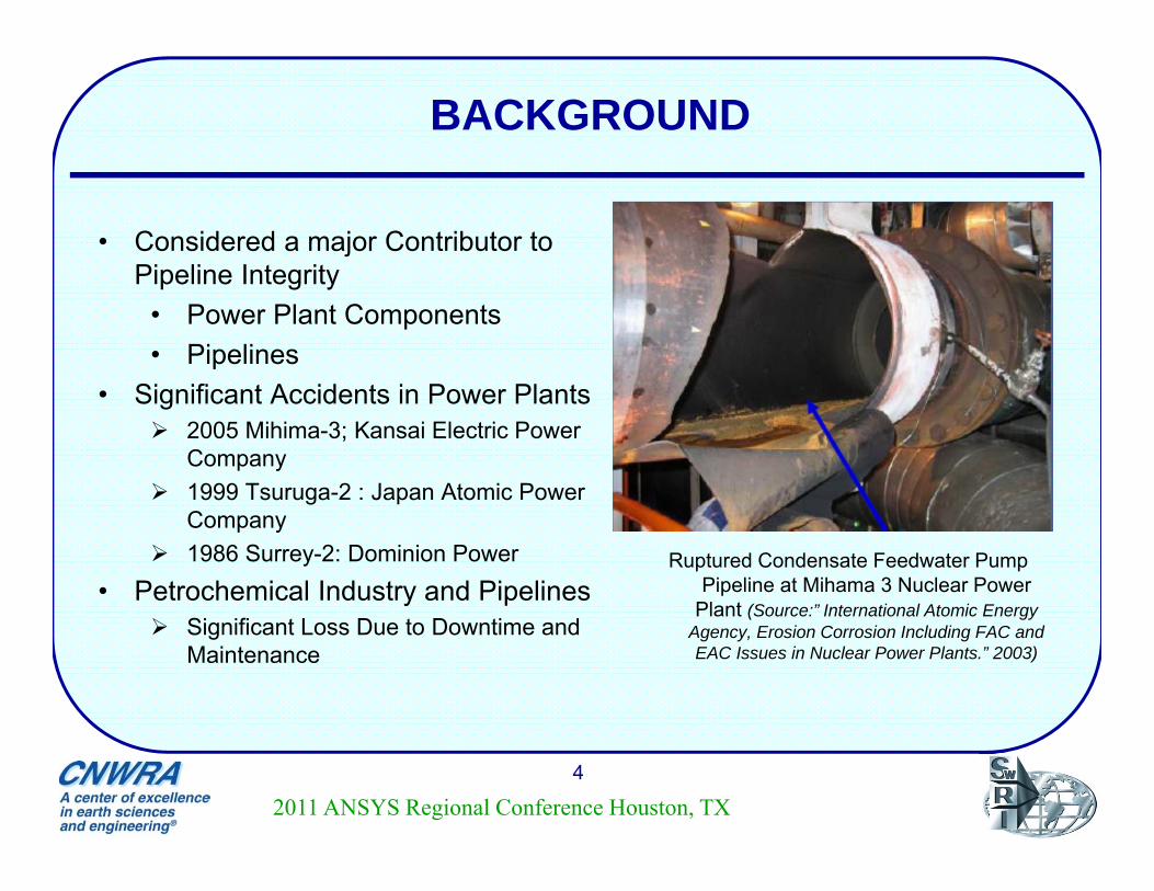
Ruptured Condensate Feedwater Pump Pipeline at Mihama 3 Nuclear Power
Plant (Source:” International Atomic Energy Agency, Erosion Corrosion Including FAC and EAC Issues in Nuclear Power Plants.” 2003)
• Considered a major Contributor to Pipeline Integrity
• Power Plant Components• Pipelines
• Significant Accidents in Power Plants 2005 Mihima-3; Kansai Electric Power
Company 1999 Tsuruga-2 : Japan Atomic Power
Company 1986 Surrey-2: Dominion Power
• Petrochemical Industry and Pipelines Significant Loss Due to Downtime and
Maintenance
2011 ANSYS Regional Conference Houston, TX
FLOW ASSISTED CORROSION MECHANISM
5
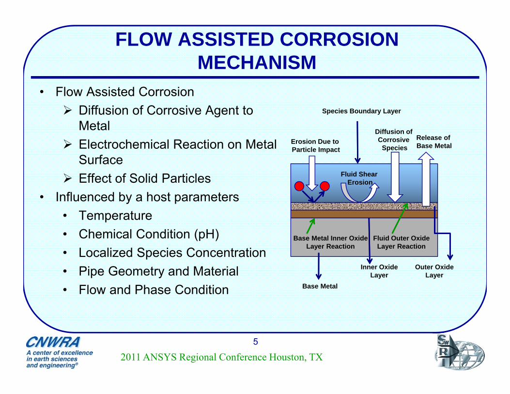
• Flow Assisted Corrosion Diffusion of Corrosive Agent to
Metal Electrochemical Reaction on Metal
Surface Effect of Solid Particles
• Influenced by a host parameters• Temperature• Chemical Condition (pH)• Localized Species Concentration• Pipe Geometry and Material• Flow and Phase Condition Base Metal
Inner OxideLayer
Outer OxideLayer
Species Boundary Layer
Diffusion of Corrosive
SpeciesRelease of Base Metal
Fluid Shear Erosion
Erosion Due to Particle Impact
Base Metal Inner OxideLayer Reaction
Fluid Outer OxideLayer Reaction
2011 ANSYS Regional Conference Houston, TX

SPECIES CONCENTRATION : ROLE OF HYDRAZINE
6
2011 ANSYS Regional Conference Houston, TX
• Reduced Use in Fossil Fuel Power Plants• Used in Nuclear Power Plants• Primarily Used as Oxygen Scavenger
Stabilizes pH Acts as Alkalinizer Reduced Stress Corrosion Cracking (SCC) in Steam Generator Tubes
• Hydrogen-Hydrazine Co-injection in BWR Primary Coolant for SCC Reduction
• N2H4-O2 Reaction Important for Corrosion Condition Calculations
Affects Species Concentration Affects Electrochemical Corrosion Potential (ECP) Oxidation at Base Metal Form Protective Magnetite Layer
OBJECTIVE
7
• Part of Ongoing Research on Development of CFD Modeling Framework to Assess Erosion-Corrosion Damage Supplement System Level Corrosion Analysis
• Presented Study Computational Assessment of Existing N2H4-O2 Chemistry Models
Reaction Kinetics Inclusion of Surface Reaction
Simulate Reaction And Wall Mass Transfer in U-Bend Pipe Component
• Assess Effect of Turbulence Models in Wall Mass Transfer
2011 ANSYS Regional Conference Houston, TX
DESCRIPTION OF THE SIMULATION TEST CASES
8
• Case-Study-1: Straight Pipe• Case Setup• Description of Chemical Kinetics• Assumptions and Simulation Conditions
• Case-Study-2: U-bend Pipe• Case Setup• Model Development and Assumptions• Mass Transfer Calculation Method
2011 ANSYS Regional Conference Houston, TX
CASE-STUDY-1 SETUP
9
2011 ANSYS Regional Conference Houston, TX
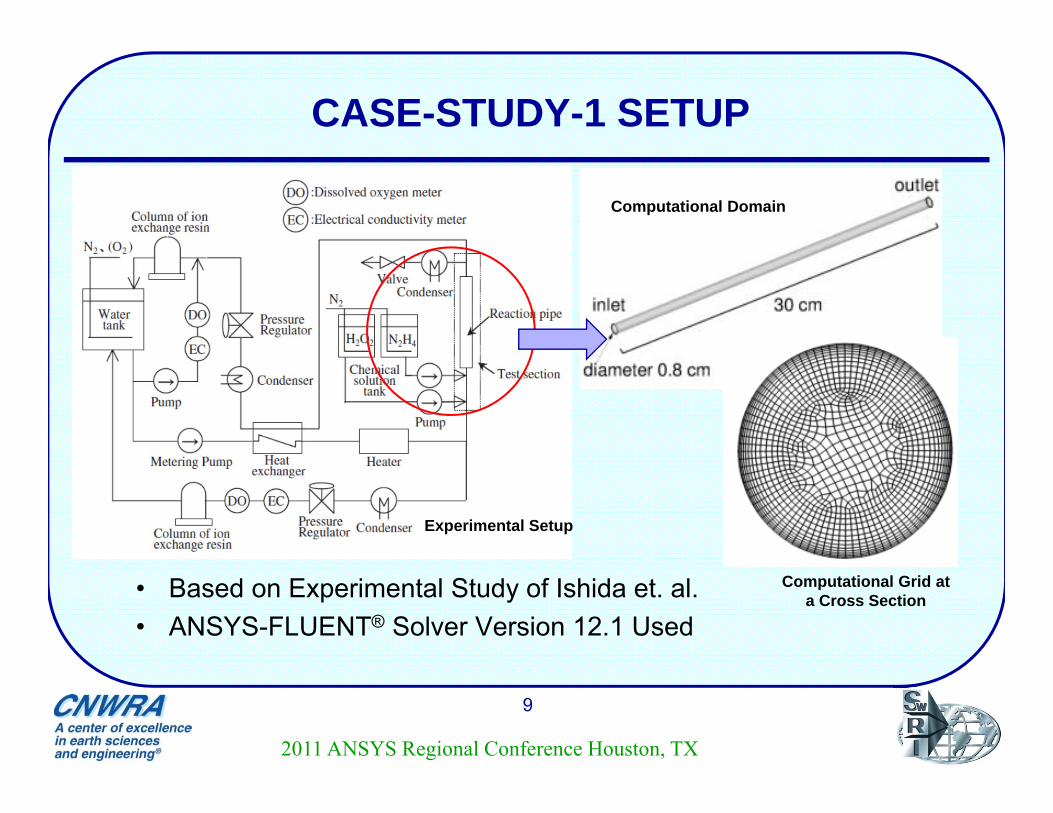
• Based on Experimental Study of Ishida et. al.• ANSYS-FLUENT® Solver Version 12.1 Used
Experimental Setup
Computational Domain
Computational Grid at a Cross Section
DESCRIPTION OF CHEMICAL KINETICS
10
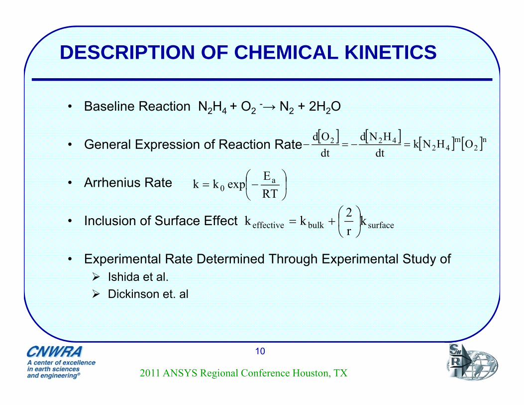
• Baseline Reaction N2H4 + O2-→ N2 + 2H2O
• General Expression of Reaction Rate
• Arrhenius Rate
• Inclusion of Surface Effect
• Experimental Rate Determined Through Experimental Study of Ishida et al. Dickinson et. al
n2m
42422 OHNk
dtHNd
dtOd
RTE
expkk a0
surfacebulkeffective kr2kk
2011 ANSYS Regional Conference Houston, TX
SIMULATION CONDITIONS AND ASSUMPTIONS
ASME 2011 Pressure Vessels & Piping Division Conference11
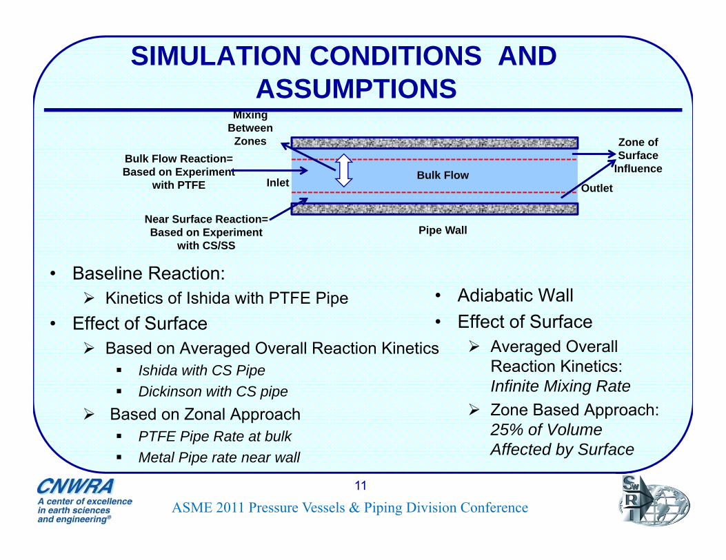
• Baseline Reaction: Kinetics of Ishida with PTFE Pipe
• Effect of Surface Based on Averaged Overall Reaction Kinetics
Ishida with CS Pipe Dickinson with CS pipe
Based on Zonal Approach PTFE Pipe Rate at bulk Metal Pipe rate near wall
Mixing Between
Zones
Near Surface Reaction= Based on Experiment
with CS/SSPipe Wall
Bulk Flow
Zone of Surface
InfluenceInlet Outlet
Bulk Flow Reaction= Based on Experiment
with PTFE
• Adiabatic Wall• Effect of Surface
Averaged Overall Reaction Kinetics: Infinite Mixing Rate
Zone Based Approach: 25% of Volume Affected by Surface
CASE-STUDY-2 SETUP
12
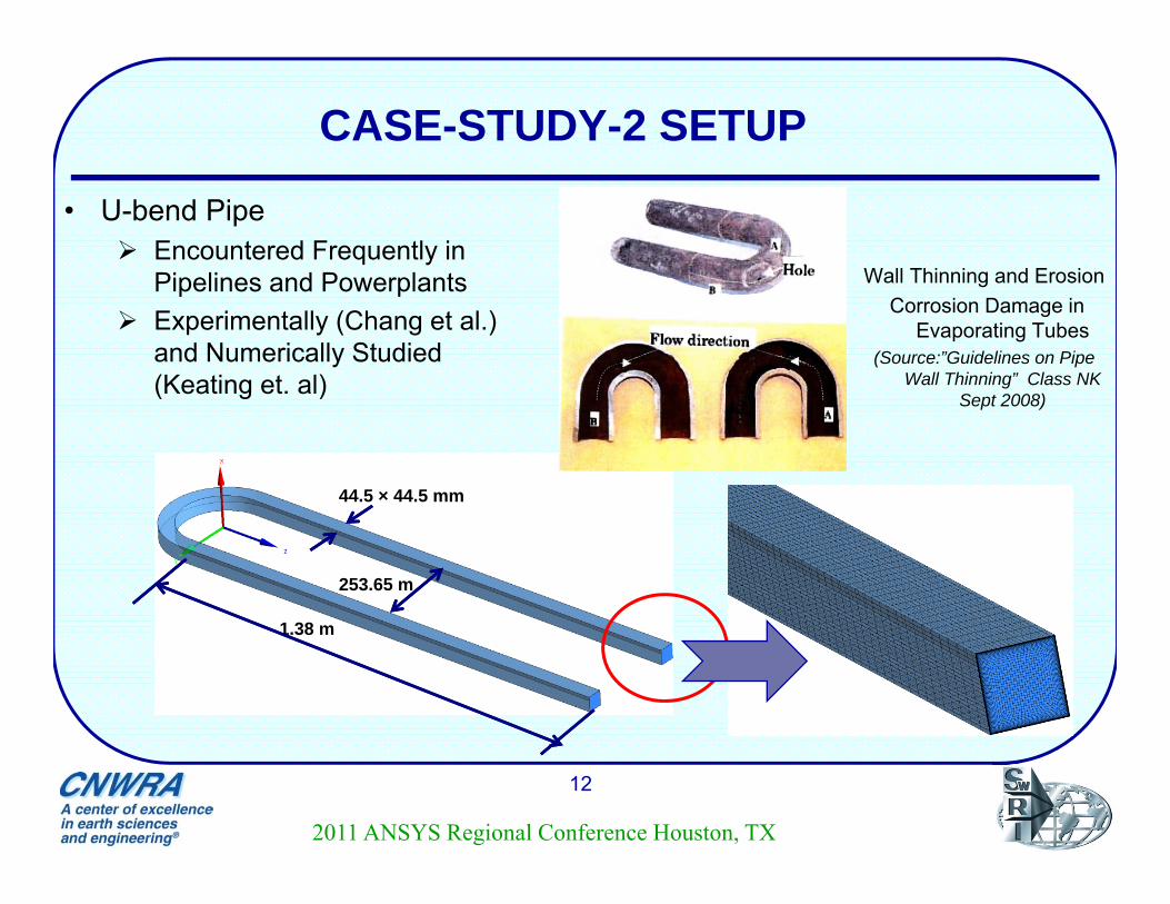
• U-bend Pipe Encountered Frequently in
Pipelines and Powerplants Experimentally (Chang et al.)
and Numerically Studied (Keating et. al)
1.38 m
253.65 m
44.5 × 44.5 mm
Wall Thinning and ErosionCorrosion Damage in
Evaporating Tubes(Source:”Guidelines on Pipe
Wall Thinning” Class NK Sept 2008)
2011 ANSYS Regional Conference Houston, TX
MODEL DEVELOPMENT AND ASSUMPTIONS
13
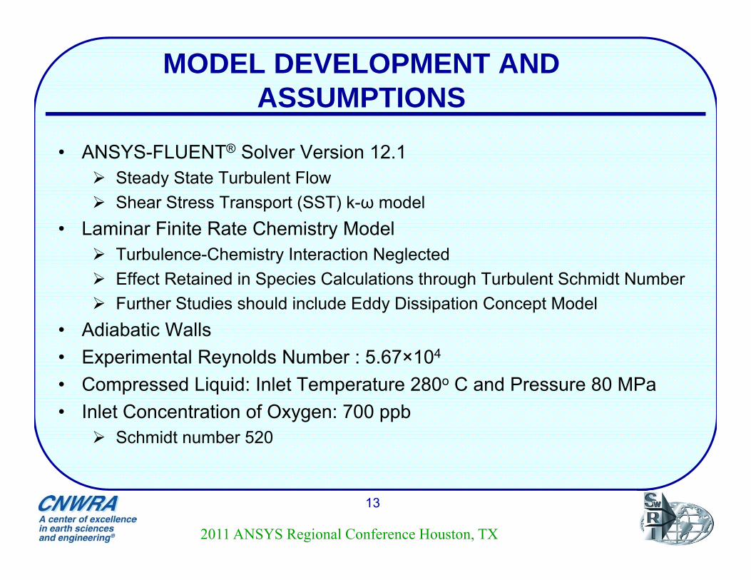
• ANSYS-FLUENT® Solver Version 12.1 Steady State Turbulent Flow Shear Stress Transport (SST) k-ω model
• Laminar Finite Rate Chemistry Model Turbulence-Chemistry Interaction Neglected Effect Retained in Species Calculations through Turbulent Schmidt Number Further Studies should include Eddy Dissipation Concept Model
• Adiabatic Walls• Experimental Reynolds Number : 5.67×10⁴
• Compressed Liquid: Inlet Temperature 280o C and Pressure 80 MPa• Inlet Concentration of Oxygen: 700 ppb
Schmidt number 520
2011 ANSYS Regional Conference Houston, TX
WALL MASS TRANSFER CALCULATION METHOD
ASME 2011 Pressure Vessels & Piping Division Conference14
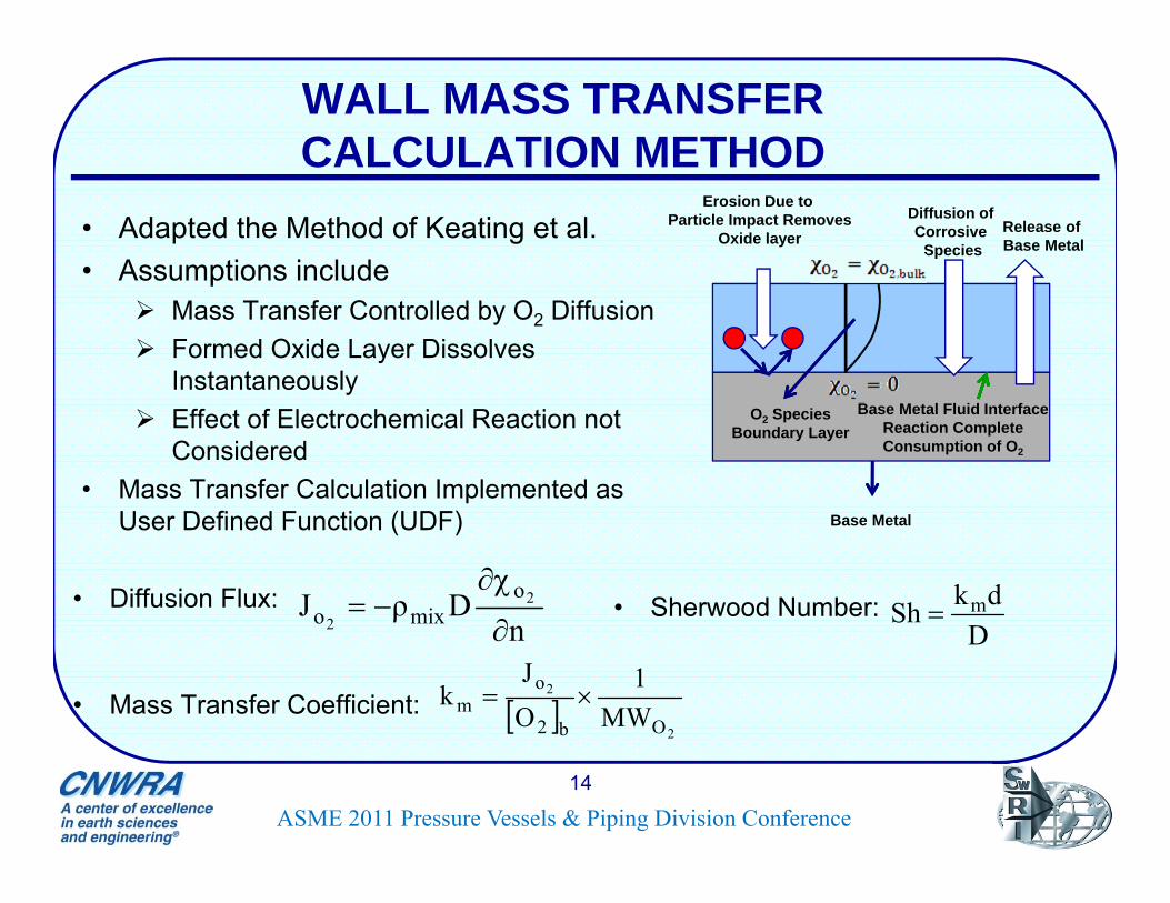
• Adapted the Method of Keating et al.• Assumptions include
Mass Transfer Controlled by O2 Diffusion Formed Oxide Layer Dissolves
Instantaneously Effect of Electrochemical Reaction not
Considered• Mass Transfer Calculation Implemented as
User Defined Function (UDF)
nDρJ 2
2
omixo
Base Metal
O2 Species Boundary Layer
Diffusion of Corrosive
SpeciesRelease of Base Metal
Erosion Due to Particle Impact Removes
Oxide layer
Base Metal Fluid Interface Reaction Complete Consumption of O2
2
2
Ob2
om MW
1OJ
k
• Diffusion Flux:
• Mass Transfer Coefficient:
• Sherwood Number: D
dkSh m
RESULTS AND DISCUSSIONS FOR TEST CASE-1
15
• Baseline Simulation, PTFE Pipe Velocity and Species Concentration for Baseline Comparison of Experimental and Computed Inlet to
Outlet N2H4 Concentration Ratio• Effect of Wall Averaged Overall Reaction Kinetics
Concentration Ratio CS Pipe
Zone Based Model Concentration Ratio
VELOCITY AND SPECIES CONCENTRATION DISTRIBUTION
16
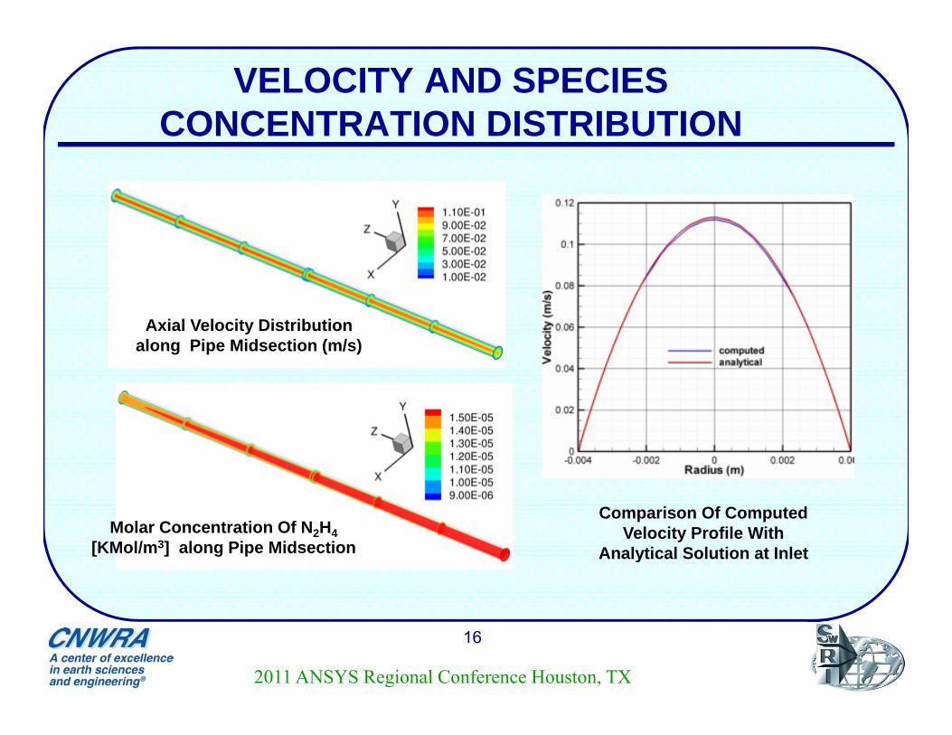
Axial Velocity Distribution along Pipe Midsection (m/s)
Comparison Of Computed Velocity Profile With
Analytical Solution at InletMolar Concentration Of N2H4
[KMol/m3] along Pipe Midsection
2011 ANSYS Regional Conference Houston, TX
BASELINE N2H4 CONCENTRATION RATIO COMPARISON
17
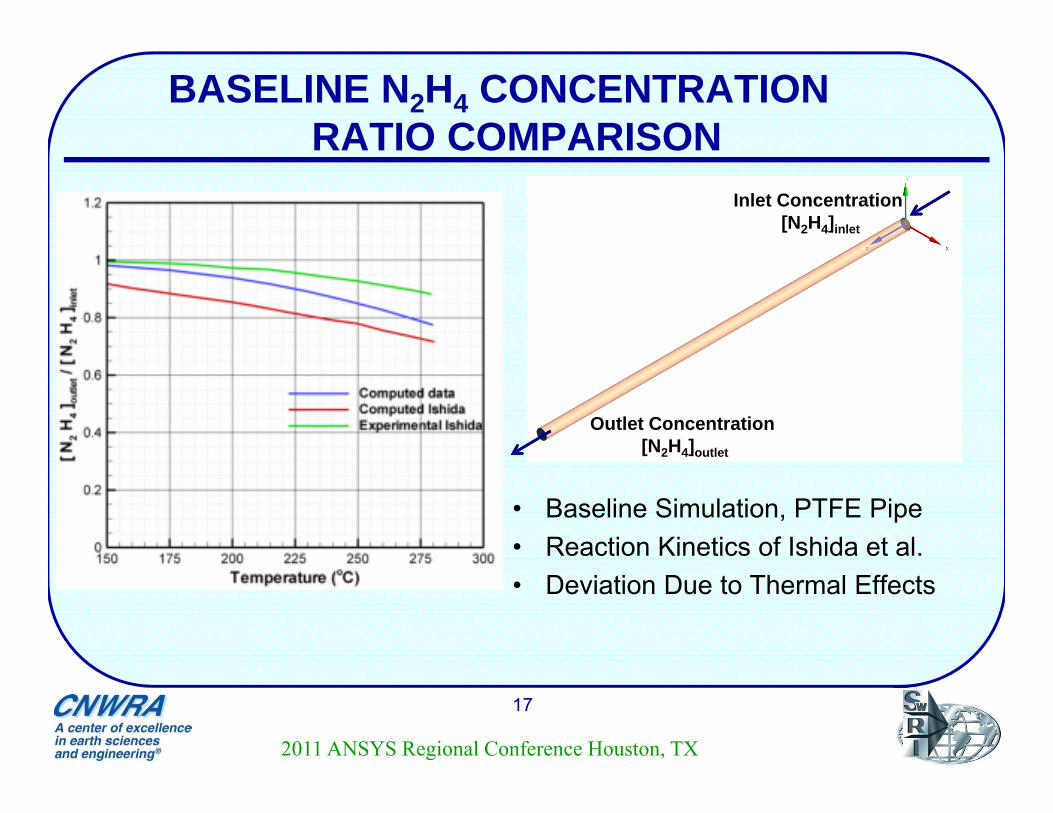
• Baseline Simulation, PTFE Pipe• Reaction Kinetics of Ishida et al.• Deviation Due to Thermal Effects
Inlet Concentration[N2H4]inlet
Outlet Concentration[N2H4]outlet
2011 ANSYS Regional Conference Houston, TX
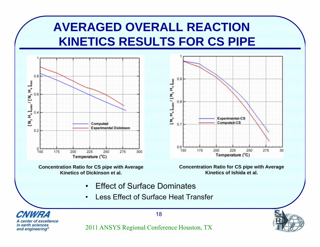
AVERAGED OVERALL REACTION KINETICS RESULTS FOR CS PIPE
18
• Effect of Surface Dominates • Less Effect of Surface Heat Transfer
Concentration Ratio for CS pipe with Average Kinetics of Dickinson et al.
Concentration Ratio for CS pipe with Average Kinetics of Ishida et al.
2011 ANSYS Regional Conference Houston, TX
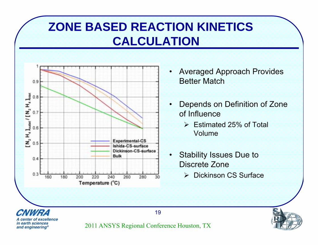
ZONE BASED REACTION KINETICS CALCULATION
19
• Averaged Approach Provides Better Match
• Depends on Definition of Zone of Influence Estimated 25% of Total
Volume
• Stability Issues Due to Discrete Zone Dickinson CS Surface
2011 ANSYS Regional Conference Houston, TX
RESULTS AND DISCUSSIONS FOR TEST CASE-2
20
• Velocity Distribution
• Species Concentration Distribution
• Mass Transfer Rate Distribution Ratio of Sherwood Number with and without Reaction Along Three Lines in the Pipe
2011 ANSYS Regional Conference Houston, TX
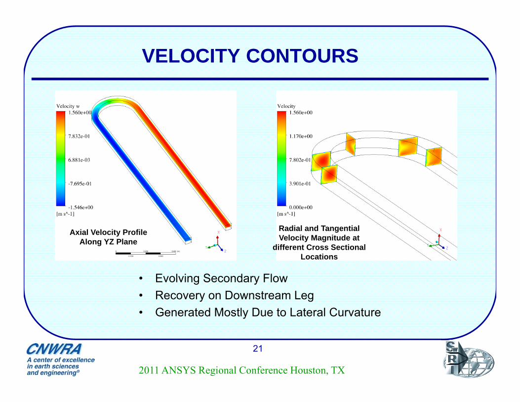
VELOCITY CONTOURS
21
• Evolving Secondary Flow• Recovery on Downstream Leg• Generated Mostly Due to Lateral Curvature
Axial Velocity Profile Along YZ Plane
Radial and Tangential Velocity Magnitude at
different Cross Sectional Locations
2011 ANSYS Regional Conference Houston, TX
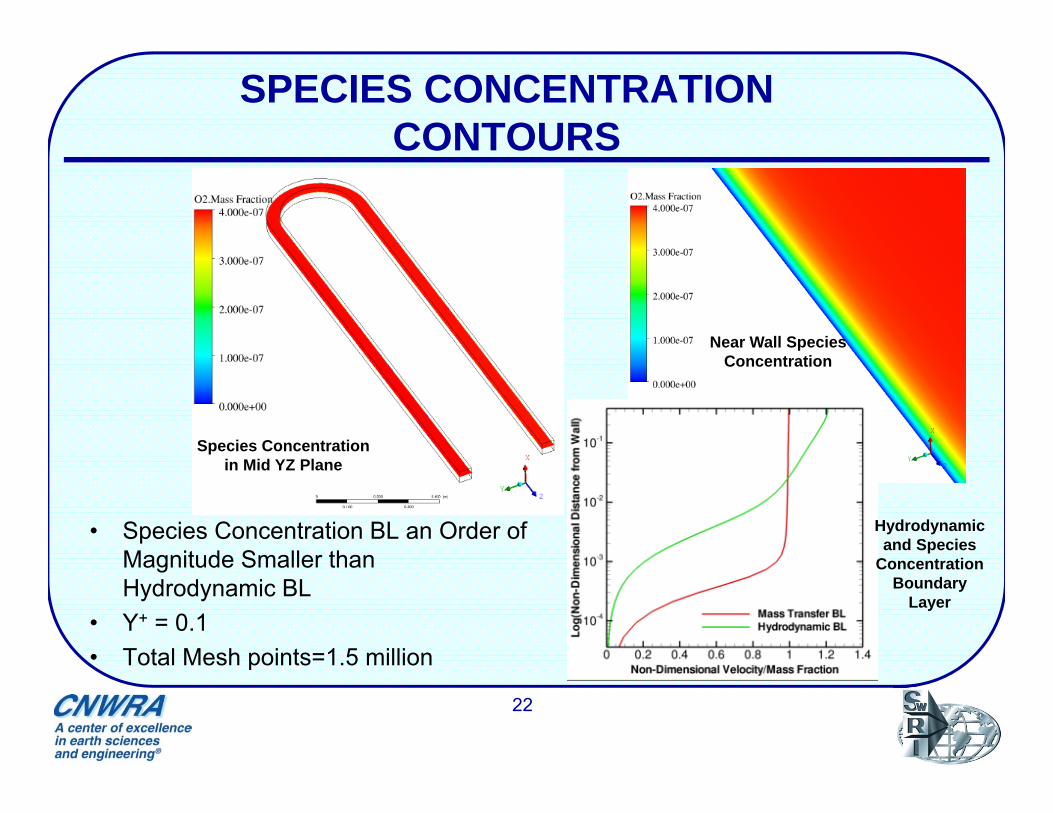
SPECIES CONCENTRATION CONTOURS
22
• Species Concentration BL an Order of Magnitude Smaller than Hydrodynamic BL
• Y+ = 0.1• Total Mesh points=1.5 million
Species Concentration in Mid YZ Plane
Near Wall Species Concentration
Hydrodynamic and Species
Concentration Boundary
Layer
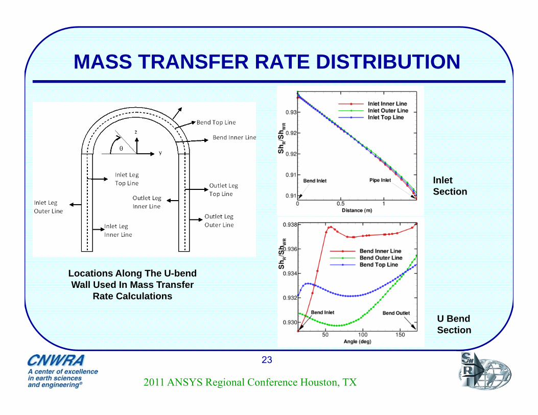
MASS TRANSFER RATE DISTRIBUTION
23
Locations Along The U-bend Wall Used In Mass Transfer
Rate Calculations
Inlet Section
U Bend Section
2011 ANSYS Regional Conference Houston, TX
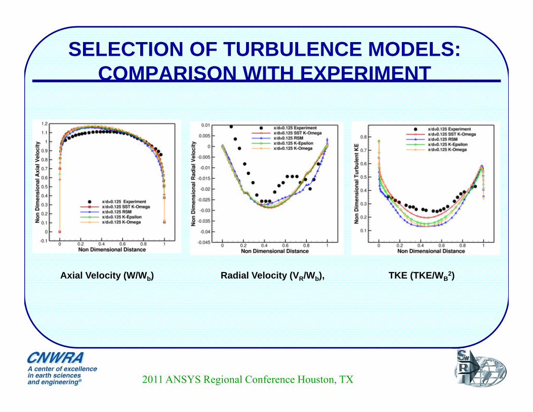
SELECTION OF TURBULENCE MODELS: COMPARISON WITH EXPERIMENT
2011 ANSYS Regional Conference Houston, TX
Axial Velocity (W/Wb) Radial Velocity (VR/Wb), TKE (TKE/WB2)
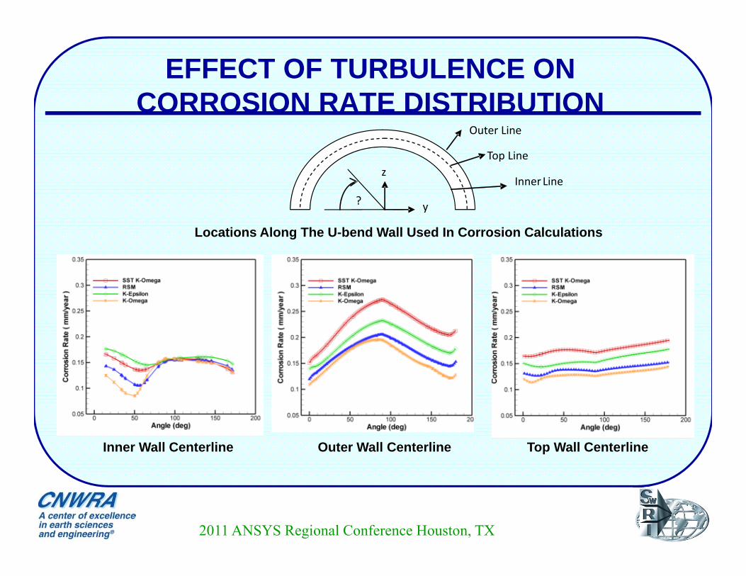
EFFECT OF TURBULENCE ON CORROSION RATE DISTRIBUTION
2011 ANSYS Regional Conference Houston, TX
Locations Along The U-bend Wall Used In Corrosion Calculations
Inner Wall Centerline Outer Wall Centerline Top Wall Centerline
y
z
Outer Line
Inner Line
Top Line
?
SUMMARY
26
• A Two Part Study to Simulate Flow and Chemistry in NPR Secondary Coolant Pipelines
• In Part-1 Used Experimentally Obtained N2H4-O2 Reaction Kinetics in Numerical Simulations Baseline Simulation without Wall Effect Study Effect of Wall
Overall Averaged Kinetics Provide Better Results
• In Part-2 Simulated a U-Bend Pipe Mass Transfer Calculation Based on Simple Diffusion Based Model
Minimal Variation at the Inlet Section Significant Impact of Secondary Flows at the Bend
Choice of Turbulence Model Important• Affects Corrosion Rate Predictions
2011 ANSYS Regional Conference Houston, TX