numerical simulation of nox formation in turbulent flames...
TRANSCRIPT

Alberto Cuoci
Numerical simulation of NOx formation in turbulent
flames through the Kinetic Post-Processing (KPP)
technique
Université Libre de Bruxelles
March 5th, 2014 – Bruxelles (Belgium)
Department of Chemistry, Materials, and Chemical Engineering
Politecnico di Milano (Italy)
Alberto Cuoci – 5th March 2014 – Université Libre de Bruxelles
2Outline
1. The CRECK Modeling Group @ Politecnico di Milano
2. Introduction
3. The Kinetic Post Processing (KPP) Technique for NOx Kinetic mechanisms for CFD applications
Reactor networks from CFD
Effects of temperature fluctuations on NOx formation
Solution of reactor networks
4. Applications to lab-scale and industrial flames Lab-scale flames
Industrial cases
5. Extension to other pollutants
6. Conclusions

Alberto Cuoci – 5th March 2014 – Université Libre de Bruxelles
3Outline
1. The CRECK Modeling Group @ Politecnico di Milano
2. Introduction
3. The Kinetic Post Processing (KPP) Technique for NOx Kinetic mechanisms for CFD applications
Reactor networks from CFD
Effects of temperature fluctuations on NOx formation
Solution of reactor networks
4. Applications to lab-scale and industrial flames Lab-scale flames
Industrial cases
5. Extension to other pollutants
6. Conclusions

Alberto Cuoci – 5th March 2014 – Université Libre de Bruxelles
4The CRECK Modeling Group
People
Full Professors Assistant Professors PhD Students
Eliseo Ranzi
Tiziano
Faravelli
Alessio
Frassoldati
Alberto Cuoci
Mattia Bissoli
Matteo Pelucchi
Chiara Saggese
Alessandro
StagniPermanent Staff
Dipartimento di Chimica, Materiali e
Ingegneria Chimica "Giulio Natta"
Politecnico di Milano
Giancarlo
Gentile
Paulo De Biagihttp://creckmodeling.chem.polimi.it/
Alberto Cuoci – 5th March 2014 – Université Libre de Bruxelles
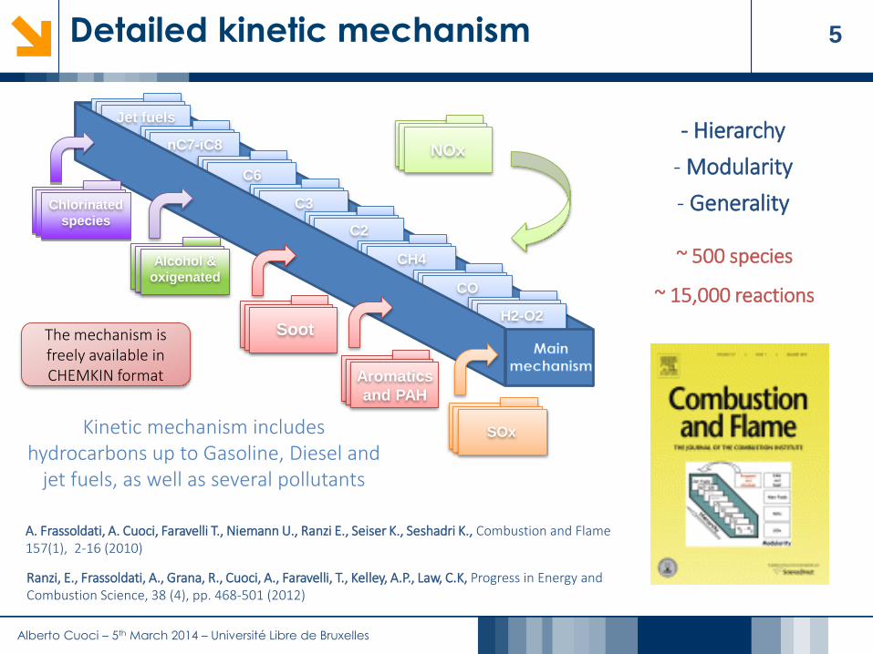
5Detailed kinetic mechanism
SOx
Jet fuels
nC7-iC8
C6
C3
C2
CH4
CO
H2-O2
NOx
Soot
Aromatics
and PAH
Alcohol &
oxigenated
Kinetic mechanism includes hydrocarbons up to Gasoline, Diesel and
jet fuels, as well as several pollutants
- Hierarchy
- Modularity
- Generality
~ 500 species
~ 15,000 reactions
Chlorinated
species
The mechanism is freely available in CHEMKIN format
A. Frassoldati, A. Cuoci, Faravelli T., Niemann U., Ranzi E., Seiser K., Seshadri K., Combustion and Flame157(1), 2-16 (2010)
Ranzi, E., Frassoldati, A., Grana, R., Cuoci, A., Faravelli, T., Kelley, A.P., Law, C.K, Progress in Energy and Combustion Science, 38 (4), pp. 468-501 (2012)

Alberto Cuoci – 5th March 2014 – Université Libre de Bruxelles
6From molecules to furnaces
Thermodynamics and transport properties
Detailed kinetic mechanisms
Ideal reactors (batch, PSR, PF, shock tubes)
1D Laminar premixed flames
2D laminar coflowflames
Non premixed turbulent jet
flames
Lab-scale turbulent flames
CFD modeling of complex combustion devices
(burners, combustors, furnaces)
Tuning and
validation
Validation
Validation
Industrial
applications
Development
chemistry
chemistry and
fluid dynamics
chemistry/turbulence
interactions
Drop tubes and thermo-gravimetric analyses
Alberto Cuoci – 5th March 2014 – Université Libre de Bruxelles
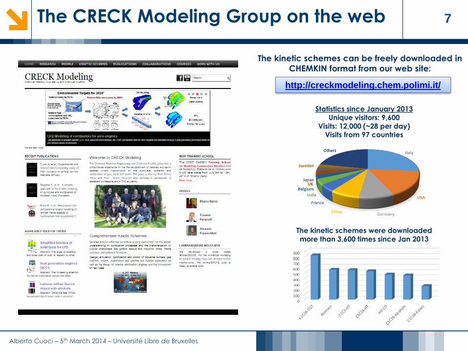
7The CRECK Modeling Group on the web
http://creckmodeling.chem.polimi.it/
The kinetic schemes can be freely downloaded in
CHEMKIN format from our web site:
Statistics since January 2013Unique visitors: 9,600
Visits: 12,000 (~28 per day)Visits from 97 countries
The kinetic schemes were downloaded more than 3,600 times since Jan 2013

Alberto Cuoci – 5th March 2014 – Université Libre de Bruxelles
8Academic and Industrial Collaborations
Academic Industrial

Alberto Cuoci – 5th March 2014 – Université Libre de Bruxelles
9Academic collaborations (I)
University of Galway
H. Curran
Oxygenated fuels
University of Yale
S. Gomez
Kinetics of real fuels
Northeastern University
Y.A. Levendis
Coal
CNRS Orléans
P. Dagaut
Large fuels
Rensselaer Polytechnic Institute
M. Oehlschlaeger
Decalin ignition
Université Libre de Bruxelles
A. Parente
Reduction of kinetic mechanisms

Alberto Cuoci – 5th March 2014 – Université Libre de Bruxelles
10Academic collaborations (II)
DTU
P. Glarborg
Kinetics of bromine and chlorine
University of San Diego
K. Seshadri, F.A. Williams
Kinetics of real fuels
Droplet combustion
University of Princeton
C.K. Law
Flame speeds
Cornell University
B. Fischer
Biomass kinetics
University of Zaragoza
M. Alzueta
Soot
North Carolina University
P. Westmoreland
Alcohol kinetics

Alberto Cuoci – 5th March 2014 – Université Libre de Bruxelles
11Academic collaborations (III)
University of Ostrava
V. Nevrly
Pulsating flames
University of Bielefeld
K. Kohse-Höinghaus
Alcohols kinetics
University of Nancy
F. Battin-Leclerc
Kinetics of large methyl-esters
KAUST University
M. Sarathy
PRIME Project
University of Adelaide
P. Medwell
MILD combustion
University of Hefei
F. Qi
Laminar, coflow flames

Alberto Cuoci – 5th March 2014 – Université Libre de Bruxelles
12Industrial collaborations
Danieli
Industrial burners (flameless)MORE
Oxy-combustion burners
and NOx
Riello
Domestic burners
Rolls-Royce Canada
NOx modeling
CSM
Combustion mechanisms
Agusta-Westland
NOX from helicopters
Technip
NOX from furnaces
Techint
Sulphur Claus
furnaces
AVIO (Napoli)
GT Combustors
ENGITEC
Oxy-combustion

Alberto Cuoci – 5th March 2014 – Université Libre de Bruxelles
13Outline
1. The CRECK Modeling Group @ Politecnico di Milano
2. Introduction
3. The Kinetic Post Processing (KPP) Technique for NOx Kinetic mechanisms for CFD applications
Reactor networks from CFD
Effects of temperature fluctuations on NOx formation
Solution of reactor networks
4. Applications to lab-scale and industrial flames Lab-scale flames
Industrial cases
5. Extension to other pollutants
6. Conclusions

Alberto Cuoci – 5th March 2014 – Université Libre de Bruxelles
14Reduction of pollutant emissions (I)
Increasingly stringent regulations for pollutant emissions
in furnaces, power plants, gas turbines, burners etc.

Alberto Cuoci – 5th March 2014 – Université Libre de Bruxelles
15Reduction of pollutant emissions (II)
Alberto Cuoci – 5th March 2014 – Université Libre de Bruxelles
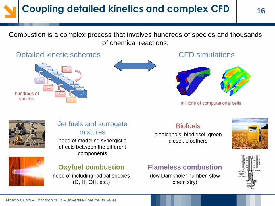
16Coupling detailed kinetics and complex CFD
Biofuelsbioalcohols, biodiesel, green
diesel, bioethers
Flameless combustion(low Damkholer number, slow
chemistry)
Oxyfuel combustionneed of including radical species
(O, H, OH, etc.)
Jet fuels and surrogate
mixturesneed of modeling synergistic
effects between the different
components
Combustion is a complex process that involves hundreds of species and thousands
of chemical reactions.
Detailed kinetic schemes CFD simulations
millions of computational cells
hundreds of
species

Alberto Cuoci – 5th March 2014 – Université Libre de Bruxelles
17Detailed kinetic mechanisms
Reaction mechanisms at various level of detail and comprehensiveness increasing effort to incorporate more
complex reaction mechanisms in
simulation of combustion processes
and this has led to the development of
reaction mechanisms with different
levels of detail and
comprehensiveness
computational cost associated with
such mechanisms is usually very high
need of computational tools to make
computationally efficient the
management of large kinetic schemes
and easy their integration in new
and/or existing numerical codes
Adapted from:
T.F. Lu, C.K. Law, Prog. Energy Comb. Sci., 35 (2009)

Alberto Cuoci – 5th March 2014 – Université Libre de Bruxelles
18Computational cost of kinetics
Cuoci, A. Frassoldati, T. Faravelli, E. Ranzi, "Numerical Modeling of Laminar Flames with Detailed Kinetics Based on the Operator-Splitting Method", Energy & Fuels, 27 (12), p. 7730-7753 (2013), DOI: 10.1021/ef4016334
Usually the computational cost of multi-dimensional CFD
simulations increases more than quadratically with respect to the
number of species
C ≈ N2.5Simulation of laminar, coflow flames fed with ethylene
(2D, structured grid, in-house code)

Alberto Cuoci – 5th March 2014 – Université Libre de Bruxelles
19Coupling between turbulence and chemistry
Strong coupling between chemistry and
turbulence in combustion processes
time [s]
no
rma
lize
d m
ass
fra
ctio
n
Inlet mixture: C3H8 + Air
Temperature: 1800 K
fuel
Adapted from: R. Fox, “Computational models for turbulent reacting
flows”, Cambridge University Press (2002)

Alberto Cuoci – 5th March 2014 – Université Libre de Bruxelles
20Coupling detailed kinetics and complex CFD
Biofuelsbioalcohols, biodiesel, green
diesel, bioethers
Flameless combustion(low Damkholer number, slow
chemistry)
Oxyfuel combustionneed of including radical species
(O, H, OH, etc.)
Jet fuels and surrogate
mixturesneed of modeling synergistic
effects between the different
components
Combustion is a complex process that involves hundreds of species and thousands
of chemical reactions.
Detailed kinetic schemes CFD simulations
millions of computational cells
hundreds of
species

Alberto Cuoci – 5th March 2014 – Université Libre de Bruxelles
21Segregated vs Coupled Algorithms
Strong non linearity of reaction terms
High stiffness
all the processes and their interactions are considered simultaneously
natural way to treat problems with multiple stiff processes
the resulting system of equations can be extremely large and the computational cost
prohibitive
Fully coupled algorithms
Fully segregated algorithms
Operator-splitting methods
easy to implement and computationally efficient unfeasible when large, stiff kinetic mechanisms
are used
usually avoid many costly matrix operations allow the best numerical method to be used
for each type of term or process the resulting algorithms can be very complex
and usually differ from term to term
Detailed kinetic schemes
Complex geometries

Alberto Cuoci – 5th March 2014 – Université Libre de Bruxelles
22The Kinetic Post Processing technique
CFD simulation Post-Processing
Detailed chemistry
temperature nitrogen oxides
a steady state CFD simulation of the
combustion device is performed using a
global kinetic mechanism, which
allows for the correct prediction of
thermal and flow fields, but which
cannot give us information on pollutant
species
pollutant species usually affect only
marginally the main combustion process
and consequently do not influence the
overall temperature and flow field
“slow” pollutant species

Alberto Cuoci – 5th March 2014 – Université Libre de Bruxelles
23Outline
1. The CRECK Modeling Group @ Politecnico di Milano
2. Introduction
3. The Kinetic Post Processing (KPP) Technique for NOx Kinetic mechanisms for CFD applications
Reactor networks from CFD
Effects of temperature fluctuations on NOx formation
Solution of reactor networks
4. Applications to lab-scale and industrial flames Lab-scale flames
Industrial cases
5. Extension to other pollutants
6. Conclusions

Alberto Cuoci – 5th March 2014 – Université Libre de Bruxelles
24The Kinetic Post Processing technique
1. CFD Simulation 2. Clustering and network construction
3. Interactions with the turbulence 4. Network solution
In each reactor a fixed temperature is assumed
These temperature is corrected to take into
account the effects of turbulent fluctuations on the
mean reaction rates
A very detailed kinetic scheme is used
High number of non linear equations
example: 100 species x 50,000 reactors = 5,000,000 eqs
Specifically conceived numerical method
fuelairfuelair
According to the
clustering, a complex
reactor network is
constructed
The clustering
reduces the overall
dimensions of the
problem
Alberto Cuoci – 5th March 2014 – Université Libre de Bruxelles
25Kinetic Post Processing in the literature
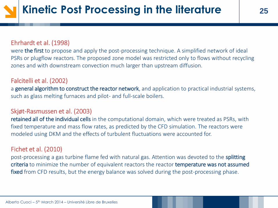
Ehrhardt et al. (1998)were the first to propose and apply the post-processing technique. A simplified network of ideal PSRs or plugflow reactors. The proposed zone model was restricted only to flows without recycling zones and with downstream convection much larger than upstream diffusion.
Falcitelli et al. (2002)a general algorithm to construct the reactor network, and application to practical industrial systems, such as glass melting furnaces and pilot- and full-scale boilers.
Skjøt-Rasmussen et al. (2003)retained all of the individual cells in the computational domain, which were treated as PSRs, with fixed temperature and mass flow rates, as predicted by the CFD simulation. The reactors were modeled using DKM and the effects of turbulent fluctuations were accounted for.
Fichet et al. (2010)post-processing a gas turbine flame fed with natural gas. Attention was devoted to the splitting criteria to minimize the number of equivalent reactors the reactor temperature was not assumed fixed from CFD results, but the energy balance was solved during the post-processing phase.

Alberto Cuoci – 5th March 2014 – Université Libre de Bruxelles
26Outline
1. The CRECK Modeling Group @ Politecnico di Milano
2. Introduction
3. The Kinetic Post Processing (KPP) Technique for NOx Kinetic mechanisms for CFD applications Reactor networks from CFD
Effects of temperature fluctuations on NOx formation
Solution of reactor networks
4. Applications to lab-scale and industrial flames Lab-scale flames
Industrial cases
5. Extension to other pollutants
6. Conclusions

Alberto Cuoci – 5th March 2014 – Université Libre de Bruxelles
27Kinetic mechanisms for CFD
Globalschemes
Detailedkinetics
Skeletalschemes
Detailed mechanisms for
hydrocarbon combustion may
include thousands of species
Lumping methodology is able to
significantly reduce its number
A further reduction is needed for
their use in multidimensional models
Hierarchical and
modular approach
Mechanism # Species # Reactions
Polimi_C1C16 500 15000
Alberto Cuoci – 5th March 2014 – Université Libre de Bruxelles
28Reacting Flux Analysis method (RFA)
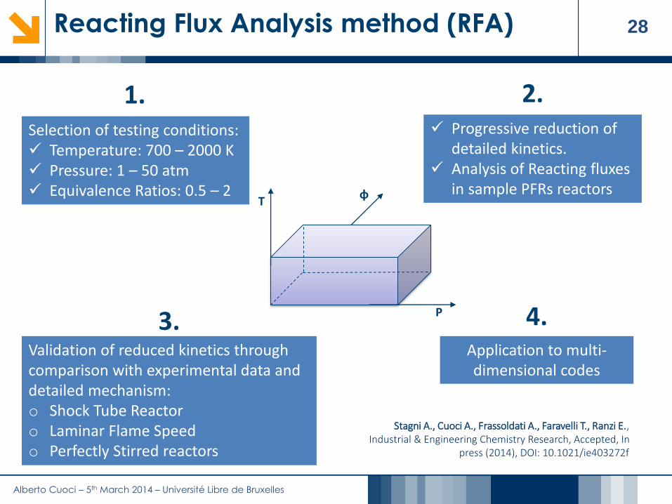
Selection of testing conditions: Temperature: 700 – 2000 K Pressure: 1 – 50 atm Equivalence Ratios: 0.5 – 2
Progressive reduction of detailed kinetics.
Analysis of Reacting fluxes in sample PFRs reactors
Validation of reduced kinetics through comparison with experimental data and detailed mechanism:o Shock Tube Reactoro Laminar Flame Speedo Perfectly Stirred reactors
1. 2.
3.Application to multi-dimensional codes
4.
T
P
φ
Stagni A., Cuoci A., Frassoldati A., Faravelli T., Ranzi E., Industrial & Engineering Chemistry Research, Accepted, In
press (2014), DOI: 10.1021/ie403272f
Alberto Cuoci – 5th March 2014 – Université Libre de Bruxelles
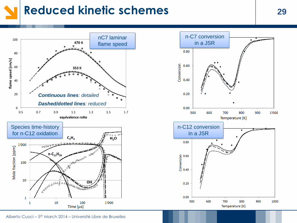
29Reduced kinetic schemes
n-C7 conversion
in a JSRnC7 laminar
flame speed
Continuous lines: detailed
Dashed/dotted lines: reduced
Species time-history
for n-C12 oxidation
n-C12 conversion
in a JSR

Alberto Cuoci – 5th March 2014 – Université Libre de Bruxelles
30Validation in coflow flames
Fuel: 3.67% NC7 96.33% N2 (vol.) @ 470K
Oxidizer: 31% O2 69% N2 (vol.) @ 300K
Velocities: 79 cm/s (F) and 68.7 cm/s (O)
de
taile
d
red
uc
ed
de
taile
d
red
uc
ed
de
taile
d
red
uc
ed
de
taile
d
red
uc
ed
de
taile
d
red
uc
ed

Alberto Cuoci – 5th March 2014 – Université Libre de Bruxelles
31Outline
1. The CRECK Modeling Group @ Politecnico di Milano
2. Introduction
3. The Kinetic Post Processing (KPP) Technique for NOx Kinetic mechanisms for CFD applications
Reactor networks from CFD Effects of temperature fluctuations on NOx formation
Solution of reactor networks
4. Applications to lab-scale and industrial flames Lab-scale flames
Industrial cases
5. Extension to other pollutants
6. Conclusions

Alberto Cuoci – 5th March 2014 – Université Libre de Bruxelles
32From the CFD simulation to the Reactor Network
exit zo
ne
Reburn
ing
zone
1st ro
whopper
2nd ro
w
Fuel
Fuel
Flue gas
Air
Flue gas
Air
Flue gas
Air
Flue gas
Air
Industrial furnace (Cassano d’Adda, 75 MW)

Alberto Cuoci – 5th March 2014 – Université Libre de Bruxelles
33The clustering procedure (II)
V1
V2
0.1 0.2 0.3 0.4
0
0.1
0.2
0.3
2192.23
2034.38
1876.52
1718.67
1560.82
1402.97
1245.11
1087.26
929.409
771.557
613.705
455.852
298
Frame 001 14 Oct 2002 Frame 001 14 Oct 2002
T [K]
V1
V2
0.1 0.2 0.3 0.4
0
0.1
0.2
0.32192.23
2034.38
1876.52
1718.67
1560.82
1402.97
1245.11
1087.26
929.409
771.557
613.705
455.852
298
Frame 001 14 Oct 2002 Frame 001 14 Oct 2002
V1
V2
0.1 0.2 0.3 0.4
0
0.1
0.2
0.32192.23
2034.38
1876.52
1718.67
1560.82
1402.97
1245.11
1087.26
929.409
771.557
613.705
455.852
298
Frame 001 14 Oct 2002 Frame 001 14 Oct 2002
V1
V2
0.1 0.2 0.3 0.4
0
0.1
0.2
0.3
Frame 001 14 Oct 2002 Frame 001 14 Oct 2002
30
120
230
V1
V2
0.1 0.2 0.3 0.4
0
0.1
0.2
0.32192.23
2034.38
1876.52
1718.67
1560.82
1402.97
1245.11
1087.26
929.409
771.557
613.705
455.852
298
Frame 001 14 Oct 2002 Frame 001 14 Oct 2002
CFD (Fluent)
V1
V2
0 0.05 0.1 0.15 0.2 0.25
0
0.02
0.04
0.06
0.08
0.1
0.12
0.14
0.16
0.18
0.2
0.22
0.24
Frame 001 17 Oct 2002 Frame 001 17 Oct 2002
V1
V2
0 0.05 0.1 0.15 0.2 0.25
0
0.02
0.04
0.06
0.08
0.1
0.12
0.14
0.16
0.18
0.2
0.22
0.24
Frame 001 17 Oct 2002 Frame 001 17 Oct 2002
V1
V2
0 0.05 0.1 0.15 0.2-0.02
0
0.02
0.04
0.06
0.08
0.1
0.12
0.14
0.16
0.18
0.2
Frame 001 17 Oct 2002 Frame 001 17 Oct 2002
V1
V2
0 0.05 0.1 0.15 0.2 0.25
0
0.02
0.04
0.06
0.08
0.1
0.12
0.14
0.16
0.18
0.2
0.22
0.24
Frame 001 17 Oct 2002 Frame 001 17 Oct 2002
V1
V2
0 0.05 0.1 0.15 0.2 0.25
0
0.02
0.04
0.06
0.08
0.1
0.12
0.14
0.16
0.18
0.2
0.22
0.24
Frame 001 17 Oct 2002 Frame 001 17 Oct 2002
V1
V2
0 0.05 0.1 0.15 0.2 0.25
0
0.02
0.04
0.06
0.08
0.1
0.12
0.14
0.16
0.18
0.2
0.22
0.24
Frame 001 17 Oct 2002 Frame 001 17 Oct 2002
V1
V2
0 0.05 0.1 0.15 0.2 0.25
0
0.02
0.04
0.06
0.08
0.1
0.12
0.14
0.16
0.18
0.2
0.22
0.24
Frame 001 17 Oct 2002 Frame 001 17 Oct 2002
V1
V2
0 0.05 0.1 0.15 0.2-0.02
0
0.02
0.04
0.06
0.08
0.1
0.12
0.14
0.16
0.18
0.2
Frame 001 17 Oct 2002 Frame 001 17 Oct 2002
V1
V2
0 0.05 0.1 0.15 0.2-0.02
0
0.02
0.04
0.06
0.08
0.1
0.12
0.14
0.16
0.18
0.2
Frame 001 17 Oct 2002 Frame 001 17 Oct 2002
V1
V2
0 0.05 0.1 0.15 0.2 0.25
0
0.02
0.04
0.06
0.08
0.1
0.12
0.14
0.16
0.18
0.2
0.22
0.24
Frame 001 17 Oct 2002 Frame 001 17 Oct 2002
V1
V2
0 0.05 0.1 0.15 0.2 0.25
0
0.02
0.04
0.06
0.08
0.1
0.12
0.14
0.16
0.18
0.2
0.22
0.24
Frame 001 17 Oct 2002 Frame 001 17 Oct 2002
V1
V2
0 0.05 0.1 0.15 0.2 0.25
0
0.02
0.04
0.06
0.08
0.1
0.12
0.14
0.16
0.18
0.2
0.22
0.24
Frame 001 17 Oct 2002 Frame 001 17 Oct 2002
V1
V2
0 0.05 0.1 0.15 0.2 0.25
0
0.02
0.04
0.06
0.08
0.1
0.12
0.14
0.16
0.18
0.2
0.22
0.24
Frame 001 17 Oct 2002 Frame 001 17 Oct 2002
V1
V2
0 0.05 0.1 0.15 0.2-0.02
0
0.02
0.04
0.06
0.08
0.1
0.12
0.14
0.16
0.18
0.2
Frame 001 17 Oct 2002 Frame 001 17 Oct 2002
V1
V2
0 0.05 0.1 0.15 0.2-0.02
0
0.02
0.04
0.06
0.08
0.1
0.12
0.14
0.16
0.18
0.2
Frame 001 17 Oct 2002 Frame 001 17 Oct 2002
V1
V2
0 0.05 0.1 0.15 0.2 0.25
0
0.02
0.04
0.06
0.08
0.1
0.12
0.14
0.16
0.18
0.2
0.22
0.24
Frame 001 17 Oct 2002 Frame 001 17 Oct 2002
V1
V2
0 0.05 0.1 0.15 0.2 0.25
0
0.02
0.04
0.06
0.08
0.1
0.12
0.14
0.16
0.18
0.2
0.22
0.24
Frame 001 17 Oct 2002 Frame 001 17 Oct 2002
V1
V2
0 0.05 0.1 0.15 0.2 0.25
0
0.02
0.04
0.06
0.08
0.1
0.12
0.14
0.16
0.18
0.2
0.22
0.24
Frame 001 17 Oct 2002 Frame 001 17 Oct 2002
V1
V2
0 0.05 0.1 0.15 0.2 0.25
0
0.02
0.04
0.06
0.08
0.1
0.12
0.14
0.16
0.18
0.2
0.22
0.24
Frame 001 17 Oct 2002 Frame 001 17 Oct 2002
V1
V2
0 0.05 0.1 0.15 0.2-0.02
0
0.02
0.04
0.06
0.08
0.1
0.12
0.14
0.16
0.18
0.2
Frame 001 17 Oct 2002 Frame 001 17 Oct 2002
V1
V2
0 0.05 0.1 0.15 0.2-0.02
0
0.02
0.04
0.06
0.08
0.1
0.12
0.14
0.16
0.18
0.2
Frame 001 17 Oct 2002 Frame 001 17 Oct 2002
V1
V2
0 0.05 0.1 0.15 0.2 0.25
0
0.02
0.04
0.06
0.08
0.1
0.12
0.14
0.16
0.18
0.2
0.22
0.24
Frame 001 17 Oct 2002 Frame 001 17 Oct 2002
V1
V2
0 0.05 0.1 0.15 0.2 0.25
0
0.02
0.04
0.06
0.08
0.1
0.12
0.14
0.16
0.18
0.2
0.22
0.24
Frame 001 17 Oct 2002 Frame 001 17 Oct 2002
V1
V2
0 0.05 0.1 0.15 0.2 0.25
0
0.02
0.04
0.06
0.08
0.1
0.12
0.14
0.16
0.18
0.2
0.22
0.24
Frame 001 17 Oct 2002 Frame 001 17 Oct 2002
V1
V2
0 0.05 0.1 0.15 0.2 0.25
0
0.02
0.04
0.06
0.08
0.1
0.12
0.14
0.16
0.18
0.2
0.22
0.24
Frame 001 17 Oct 2002 Frame 001 17 Oct 2002
0.0
0.1
0.0
0.1
0.0
0.1
0.0
0.1
0.0 0.05 0.10 0.15 0. 20
70 reattori
300 reattori
1000 reattori
Fluent
0
5
10
15
20
25
30
0 50 100 150 200 250 300
Number of Reactors
Em
issio
ni N
Ox
[pp
m]
Swirl Number = 0.9
Alberto Cuoci – 5th March 2014 – Université Libre de Bruxelles
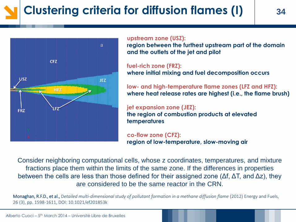
34Clustering criteria for diffusion flames (I)
upstream zone (USZ):region between the furthest upstream part of the domain and the outlets of the jet and pilot
fuel-rich zone (FRZ):where initial mixing and fuel decomposition occurs
low- and high-temperature flame zones (LFZ and HFZ):where heat release rates are highest (i.e., the flame brush)
jet expansion zone (JEZ): the region of combustion products at elevated temperatures
co-flow zone (CFZ):region of low-temperature, slow-moving air
Consider neighboring computational cells, whose z coordinates, temperatures, and mixture
fractions place them within the limits of the same zone. If the differences in properties
between the cells are less than those defined for their assigned zone (Δf, ΔT, and Δz), they
are considered to be the same reactor in the CRN.
Monaghan, R.F.D., et al., Detailed multi-dimensional study of pollutant formation in a methane diffusion flame (2012) Energy and Fuels, 26 (3), pp. 1598-1611, DOI: 10.1021/ef201853k

Alberto Cuoci – 5th March 2014 – Université Libre de Bruxelles
35Clustering criteria for diffusion flames (II)
40/42000 reactors 270/42000 reactors 1400/42000 reactors
NO mass fraction fields
In the first guesses, coarse meshes with a
high level of clustering are adopted
The calculations are then iteratively
performed using a progressively increased
number of cells up to convergence, i.e
without further grid sensitivity
The NOx-Postprocessor typically reduces
the number of the original grid-cells with a
factor of ~10

Alberto Cuoci – 5th March 2014 – Université Libre de Bruxelles
36The mass balance equations
t
i i
t
JSc
Diffusion flux due to concentration
gradients and velocity fluctuations
of the turbulent flow
Convection Chemical
reactions
Diffusion
1 1
0
*
, ,
Ns Nsout out
n i n i i n n i i
n n
W W J S V
Vaporization
Devolatilization
Alberto Cuoci – 5th March 2014 – Université Libre de Bruxelles
37Outline
1. The CRECK Modeling Group @ Politecnico di Milano
2. Introduction
3. The Kinetic Post Processing (KPP) Technique for NOx Kinetic mechanisms for CFD applications
Reactor networks from CFD
Effects of temperature fluctuations on NOx formation Solution of reactor networks
4. Applications to lab-scale and industrial flames Lab-scale flames
Industrial cases
5. Extension to other pollutants
6. Conclusions
Alberto Cuoci – 5th March 2014 – Université Libre de Bruxelles
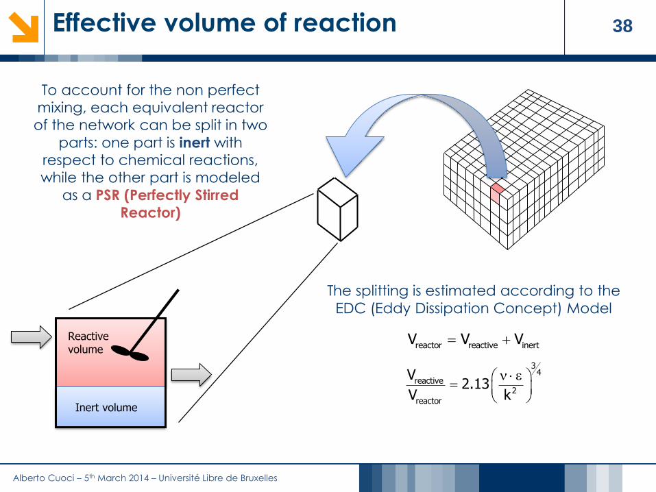
38Effective volume of reaction
To account for the non perfect
mixing, each equivalent reactor
of the network can be split in two
parts: one part is inert with respect to chemical reactions,
while the other part is modeled
as a PSR (Perfectly Stirred
Reactor)
Reactive volume
Inert volume
reactor reactive inertV V V
34
reactive2
reactor
V2.13
V k
The splitting is estimated according to the
EDC (Eddy Dissipation Concept) Model

Alberto Cuoci – 5th March 2014 – Université Libre de Bruxelles
39Fluctuations of temperature and NOx
C2H4 Air
Products
Perfectly stirred reactor
cycle number
mo
le f
ractio
n
Steady value
Slow chemistry: NO
mean temperature [K]
mo
le fr
actio
n
Mean
value
The fluctuations of temperature have a strong impact on the formation of NOX because of the high activation energy of
the thermal path

Alberto Cuoci – 5th March 2014 – Université Libre de Bruxelles
40Correction coefficient for reaction rates (I)
Rate constant is highly non linear
function of temperature
( ) exp attEk T A T
RT
fluctuation amplitude
co
rre
ction
co
eff
icie
nt C
c
A. Cuoci, A. Frassoldati, G. Buzzi Ferraris, T. Faravelli, E. Ranzi, International Journal of Hydrogen Energy (32), p. 3486-3500 (2007)
max
min
T
T
C
k T p T dTC
k T
Introduction of a proper probability
distribution function p(T)
max
min
( )T
CT
k T k T p T dT C k T
β-PDF
Requires the knowledge of the
variance of temperature
Correction
coefficient

Alberto Cuoci – 5th March 2014 – Université Libre de Bruxelles
41Correction coefficient for reaction rates (II)
The correction Coefficient
is significantly 1 for high
activation energies
(Thermal NOx)
0
2e-4
4e-4
6e-4
8e-4
0 0.2 0.4 0.6 0.8 1
Time [s]
NO
mass fra
ction
T=2000 300 [K] (sinusoidal)
oscillating profile
Uncorrected: k=k(T)
Φ=0.95 CH4/Air
Corrected: k=k(T)*Cc 2e-5
4e-5
6e-5
NO
mass fra
ction
0 0.2 0.4 0.6 0.8 1Time [s]
T=1500 500 [K] (sinusoidal)
The error (<15%) is due to the fluctuations of composition (neglected)
mean value
fluctuation amplitude
co
rre
ction
co
eff
icie
nt C
c
co
rre
ction
co
eff
icie
nt C
cfluctuation amplitude

Alberto Cuoci – 5th March 2014 – Université Libre de Bruxelles
42Calculation of correction coefficients
''2 ''2 ''2T T
T T
T T T 2 T T C Tt Sc Sc
v
Transport equation for the variance of temperature
Tabulation of Correction Coefficients
max
min
T
T
C
k T p T dTC
k T
Since during the post-processing phase the temperature is fixed in each reactor, the
correction can be pre-calculated and stored in memory (i.e. it is always the same, since it is
independent of the composition)
The correction coefficient must be calculated for each reaction in each reactor

Alberto Cuoci – 5th March 2014 – Université Libre de Bruxelles
43Outline
1. The CRECK Modeling Group @ Politecnico di Milano
2. Introduction
3. The Kinetic Post Processing (KPP) Technique for NOx Kinetic mechanisms for CFD applications
Reactor networks from CFD
Effects of temperature fluctuations on NOx formation
Solution of reactor networks
4. Applications to lab-scale and industrial flames Lab-scale flames
Industrial cases
5. Extension to other pollutants
6. Conclusions

Alberto Cuoci – 5th March 2014 – Université Libre de Bruxelles
44Numerical solution of the reactor network
Reactor Network
Negligible influence of minor species
on temperature and velocity fieldsSkeletal kinetics to
assess CFD
Multi-technique
solution strategy
Only mass
balances are solved in CRN
HYPOTHESIS
Alberto Cuoci – 5th March 2014 – Université Libre de Bruxelles
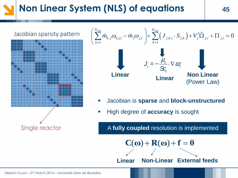
45Non Linear System (NLS) of equations
Ji= -
mt
Sct
×Ñwi
LinearLinear
Non Linear
(Power Law)
Jacobian is sparse and block-unstructured
High degree of accuracy is sought
A fully coupled resolution is implemented
*
, k, j, , , , , , ,
1 1
0AD ADN N
k j i j j i j k i j k j j i j i
k k
m m J S V
( ) ( ) C ω R ω f 0
Jacobian sparsity pattern
Single reactor
Linear Non-Linear External feeds
Alberto Cuoci – 5th March 2014 – Université Libre de Bruxelles
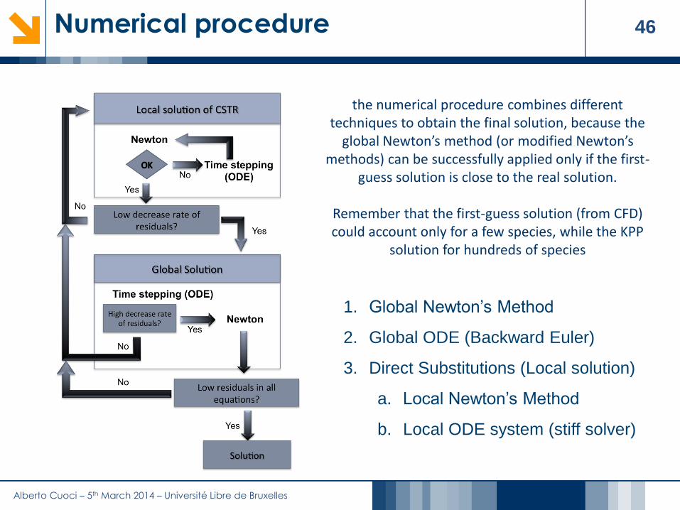
46Numerical procedure
1. Global Newton’s Method
2. Global ODE (Backward Euler)
3. Direct Substitutions (Local solution)
a. Local Newton’s Method
b. Local ODE system (stiff solver)
the numerical procedure combines different techniques to obtain the final solution, because the
global Newton’s method (or modified Newton’s methods) can be successfully applied only if the first-
guess solution is close to the real solution.
Remember that the first-guess solution (from CFD) could account only for a few species, while the KPP
solution for hundreds of species
Alberto Cuoci – 5th March 2014 – Université Libre de Bruxelles
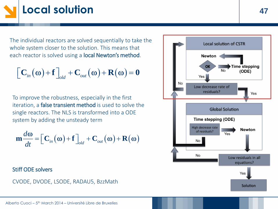
47Local solution
in outold C f C R 0
in outold
d
dt m C f C R
The individual reactors are solved sequentially to take the whole system closer to the solution. This means that each reactor is solved using a local Newton’s method.
To improve the robustness, especially in the first iteration, a false transient method is used to solve the single reactors. The NLS is transformed into a ODE system by adding the unsteady term
Stiff ODE solvers
CVODE, DVODE, LSODE, RADAU5, BzzMath

Alberto Cuoci – 5th March 2014 – Université Libre de Bruxelles
48Global solution
C R f 0
Linear System solvers
MUMPS 4.10 (Direct Solver)
LIS 1.24 (Iterative Solver)
1
1 1n n
n n
tott
m C R f
the global Newton’s method, to ensure the accuracy needed to correctly predict chemical species present in very small amounts (ppm or smaller)
When complex flows are investigated, the sequential approach (i.e., direct substitutions) could not be enough to reduce the residuals of equations to sufficiently small values to successfully apply the global Newton’s method. In such a case, a global time-stepping procedure must be taken into account.
Alberto Cuoci – 5th March 2014 – Université Libre de Bruxelles
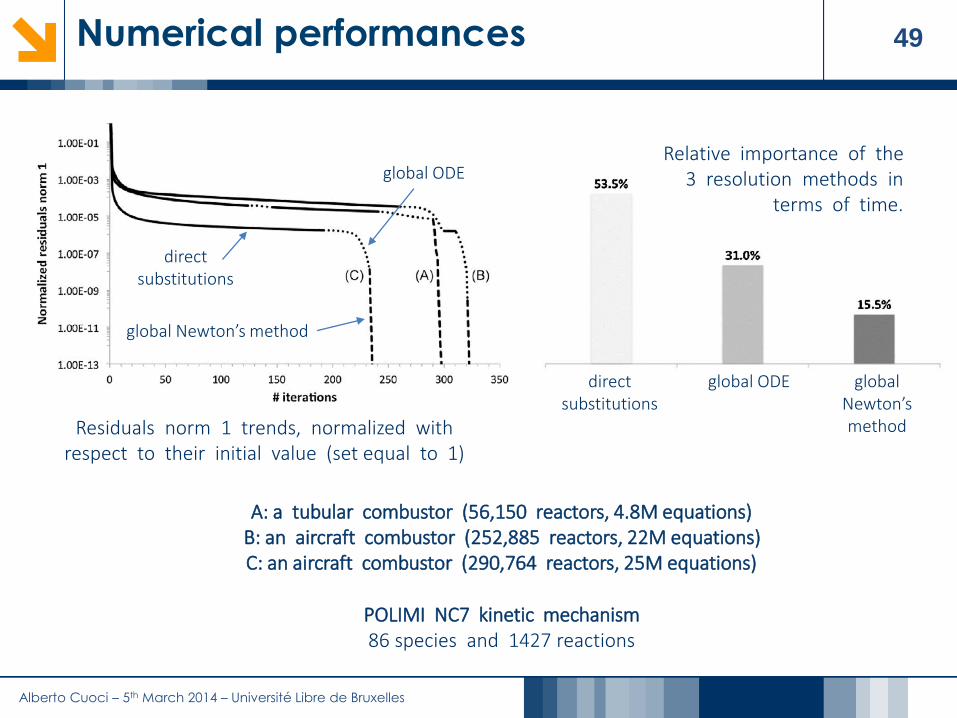
49Numerical performances
direct substitutions
global ODE
global Newton’s method
Residuals norm 1 trends, normalized with respect to their initial value (set equal to 1)
direct substitutions
global ODE global Newton’s method
Relative importance of the 3 resolution methods in
terms of time.
A: a tubular combustor (56,150 reactors, 4.8M equations)B: an aircraft combustor (252,885 reactors, 22M equations)C: an aircraft combustor (290,764 reactors, 25M equations)
POLIMI NC7 kinetic mechanism86 species and 1427 reactions

Alberto Cuoci – 5th March 2014 – Université Libre de Bruxelles
50Outline
1. The CRECK Modeling Group @ Politecnico di Milano
2. Introduction
3. The Kinetic Post Processing (KPP) Technique for NOx Kinetic mechanisms for CFD applications
Reactor networks from CFD
Effects of temperature fluctuations on NOx formation
Solution of reactor networks
4. Applications to lab-scale and industrial flames Lab-scale flames Industrial cases
5. Extension to other pollutants
6. Conclusions
Alberto Cuoci – 5th March 2014 – Université Libre de Bruxelles
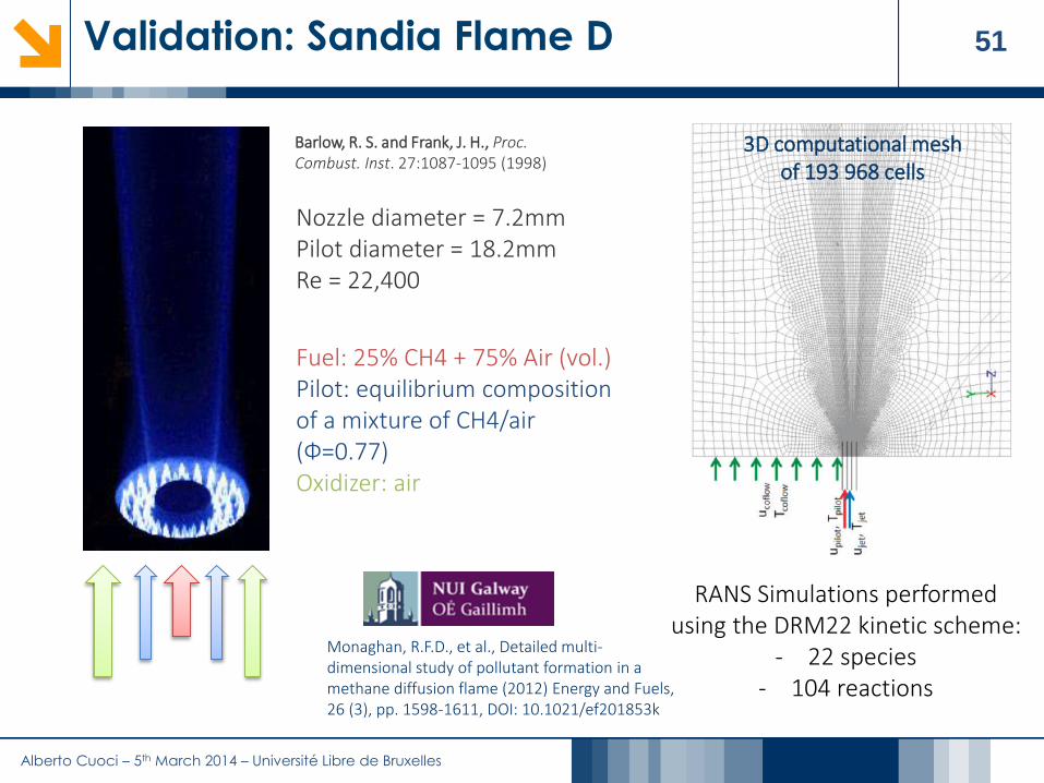
51Validation: Sandia Flame D
3D computational mesh of 193 968 cells
Fuel: 25% CH4 + 75% Air (vol.)Pilot: equilibrium composition of a mixture of CH4/air (Ф=0.77)Oxidizer: air
Barlow, R. S. and Frank, J. H., Proc. Combust. Inst. 27:1087-1095 (1998)
Nozzle diameter = 7.2mmPilot diameter = 18.2mmRe = 22,400
RANS Simulations performed using the DRM22 kinetic scheme:
- 22 species- 104 reactions
Monaghan, R.F.D., et al., Detailed multi-dimensional study of pollutant formation in a methane diffusion flame (2012) Energy and Fuels, 26 (3), pp. 1598-1611, DOI: 10.1021/ef201853k

Alberto Cuoci – 5th March 2014 – Université Libre de Bruxelles
52CFD results vs KPP results
centerline
centerline
centerline
Radial
locations
Radial
locations
Radial
locations
Continuous lines: KPP predictions
Dashed lines: CFD predictions
1114 Reactors
(less than 1% of the original cells)
103 species and 582 reactions
z/d = 75
z/d = 45
z/d = 30
Alberto Cuoci – 5th March 2014 – Université Libre de Bruxelles
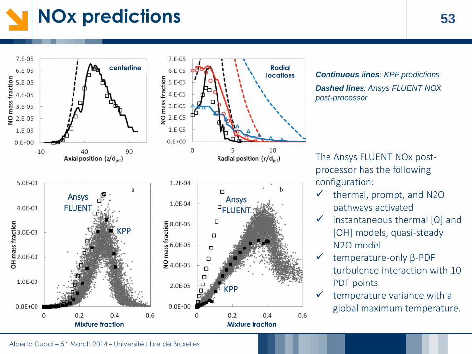
53NOx predictions
Continuous lines: KPP predictions
Dashed lines: Ansys FLUENT NOX
post-processor
centerline Radial
locations
Mixture fraction Mixture fraction
KPP
Ansys FLUENT
Ansys FLUENT
KPP
The Ansys FLUENT NOx post-processor has the following configuration: thermal, prompt, and N2O
pathways activated instantaneous thermal [O] and
[OH] models, quasi-steady N2O model
temperature-only β-PDF turbulence interaction with 10 PDF points
temperature variance with a global maximum temperature.

Alberto Cuoci – 5th March 2014 – Université Libre de Bruxelles
54Numerical performances
NUIG C2
103 species
582 reactions
GRI 3.0
53 species
325 reactions
GRI 1.2
32 species
279 reactions
Alberto Cuoci – 5th March 2014 – Université Libre de Bruxelles
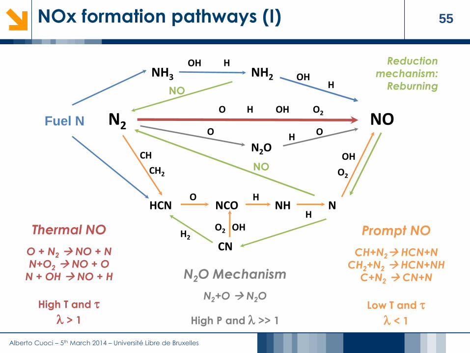
55NOx formation pathways (I)
NON2
H OH O2O
Thermal NO
O + N2 NO + N
N+O2 NO + O
N + OH NO + H
High T and t
l > 1
HCN NCO NH N
CH
CH2
O H
H
OH
O2
NH2 OHH
OH HNH3
Fuel N
OHO2
CNH2
NO
NO
Reduction
mechanism:
Reburning
N2O
O OH
N2O Mechanism
N2+O N2O
High P and l >> 1
Prompt NO
CH+N2 HCN+N
CH2+N2 HCN+NH
C+N2 CN+N
Low T and t
l < 1

Alberto Cuoci – 5th March 2014 – Université Libre de Bruxelles
56NOx formation pathways (II)
• Thermal NOx (Zeldovich)- Direct N2 oxidation.- High temperature required (> 1800 K). Highly temperature dependent
• Prompt NOx (Fenimore)- NN bond scission by fuel radicals (CH+N2=HCN+N).- Occurs in flame fronts. Not significantly temperature dependent
• N2O Pathway- Through N2+ O + M N2O + M.- Relevant under elevated pressures and lean combustion (gas turbines)
• Fuel NOx- NO formation from N-containing fuel fragments (CN, NH).- Relevant if fuel contains chemically-bound nitrogen.

Alberto Cuoci – 5th March 2014 – Université Libre de Bruxelles
57NOx Pathway Analysis
Thermal pathway
Prompt pathway
N2O pathway
NO2 pathway
Radial position z/d = 75
completeSum of single
pathways
Of the total NOx produced by the Sandia D flame, 47% is due to the
prompt pathway, 32% is due to the N2O pathway, and 21% is due to
the thermal pathway.

Alberto Cuoci – 5th March 2014 – Université Libre de Bruxelles
58Reaction channels
Important reaction channels for NO production in the high-temperature flame brush.
Important reaction channels for NO consumption in the fuel-rich region.
Rates of production of NO

Alberto Cuoci – 5th March 2014 – Université Libre de Bruxelles
59Validation: Sandia Syngas Flames
CO / H2 / N2 Jet Flames1
Unconfined turbulent jet flame in
low-velocity coflow
Fuel composition:
40% CO, 30% H2, 30% N2
Fuel inlet velocity: ~ 45-76 m/s
Air Fuel
Computational domain
Non uniform, structured mesh
About 42,000 cells (320x130)
High resolution in the region close to the inlets
Com
bustion
cham
ber
CFD Simulation details
CFD Code FLUENT 6.3.2
Space 2D Axial-Symmetric
Time Steady
Turbulence modeling Standard κ-ε turbulence model
Wall treatment Standard wall functions
Radiation Discrete Ordinate Model
Solver Segregated implicit solver
Spatial resolution Second-Order Upwind scheme
Pressure Interpolation PRESTO!
Combustion model Eddy Dissipation Concept (EDC)
POLIMI_COH2 kinetic scheme
13 species
37 reactions
1 Barlow, R.S., et al., Sandia/ETH-Zurich
CO/H2/N2 Flame Data - Release 1.1.
www.ca.sandia.gov/TNF, Sandia National
Laboratories, 2002

Alberto Cuoci – 5th March 2014 – Université Libre de Bruxelles
60Validation: Sandia Syngas Flames
temperature
axial velocityturbulent kinetic energy
Temperature
[K]
axial coordinate [mm]te
mp
era
ture
[K
]
radial coordinate [mm]
turb
ule
nt
kin
eti
c e
ne
rgy
[m2
/s]
radial coordinate [mm]
ve
loc
ity [
m/s
]
POLIMI_COH2NOX32 species
178 reactions
Number of Reactors:2,500 (%5 of original
number of cells)
KPP

Alberto Cuoci – 5th March 2014 – Université Libre de Bruxelles
61Validation: Sandia Syngas Flames
NO mass fraction Axial profiles
axial coordinate [mm]
NO
ma
ss fra
ctio
n
axial coordinate [mm]
NO
ma
ss fra
ctio
n
radial coordinate [mm]
NO
ma
ss fra
ctio
n
radial coordinate [mm]
NO
ma
ss fra
ctio
n
Radial profiles
Barlow, R.S., et al., Sandia/ETH-Zurich CO/H2/N2 Flame Data - Release 1.1. www.ca.sandia.gov/TNF, Sandia
National Laboratories, 2002
Alberto Cuoci – 5th March 2014 – Université Libre de Bruxelles
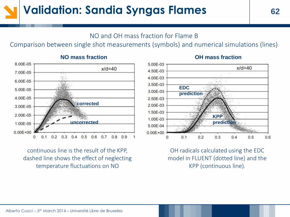
62Validation: Sandia Syngas Flames
EDC
prediction
KPP
predictionuncorrected
corrected
NO mass fraction OH mass fraction
NO and OH mass fraction for Flame BComparison between single shot measurements (symbols) and numerical simulations (lines)
continuous line is the result of the KPP, dashed line shows the effect of neglecting
temperature fluctuations on NO
OH radicals calculated using the EDC model in FLUENT (dotted line) and the
KPP (continuous line).
Alberto Cuoci – 5th March 2014 – Université Libre de Bruxelles
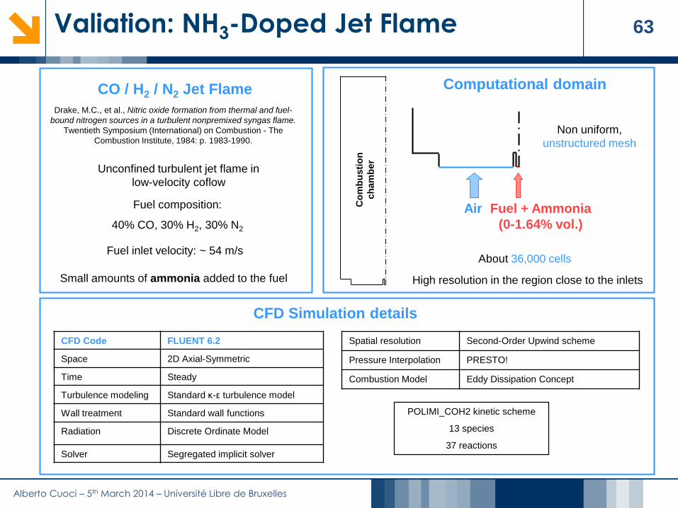
63Valiation: NH3-Doped Jet Flame
CO / H2 / N2 Jet Flame
Unconfined turbulent jet flame in
low-velocity coflow
Fuel composition:
40% CO, 30% H2, 30% N2
Small amounts of ammonia added to the fuel
Fuel inlet velocity: ~ 54 m/s
Air Fuel + Ammonia
(0-1.64% vol.)
Computational domain
Non uniform,
unstructured mesh
About 36,000 cells
High resolution in the region close to the inlets
Co
mb
usti
on
ch
am
ber
CFD Simulation details
CFD Code FLUENT 6.2
Space 2D Axial-Symmetric
Time Steady
Turbulence modeling Standard κ-ε turbulence model
Wall treatment Standard wall functions
Radiation Discrete Ordinate Model
Solver Segregated implicit solver
Spatial resolution Second-Order Upwind scheme
Pressure Interpolation PRESTO!
Combustion Model Eddy Dissipation Concept
Drake, M.C., et al., Nitric oxide formation from thermal and fuel-
bound nitrogen sources in a turbulent nonpremixed syngas flame.
Twentieth Symposium (International) on Combustion - The
Combustion Institute, 1984: p. 1983-1990.
POLIMI_COH2 kinetic scheme
13 species
37 reactions

Alberto Cuoci – 5th March 2014 – Université Libre de Bruxelles
64Valiation: NH3-Doped Jet Flame
NO at the exit
POLIMI_COH2NOX32 species
178 reactions
Number of Reactors:2,000 (%5 of original
number of cells)
KPP
NO yield at the exit
NO radial
profile
Alberto Cuoci – 5th March 2014 – Université Libre de Bruxelles
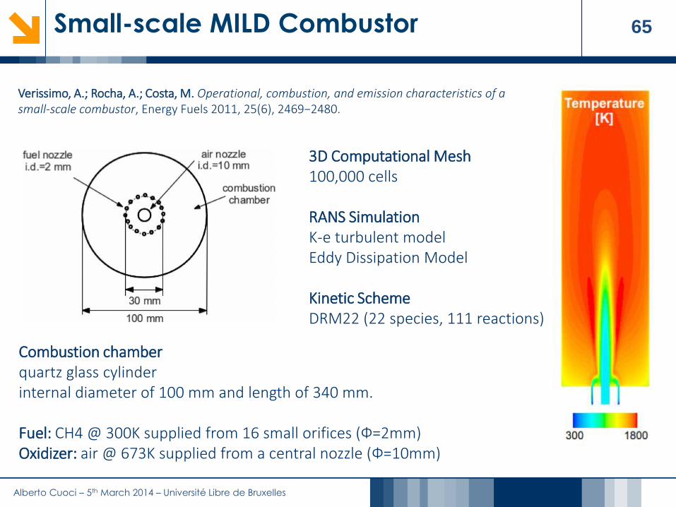
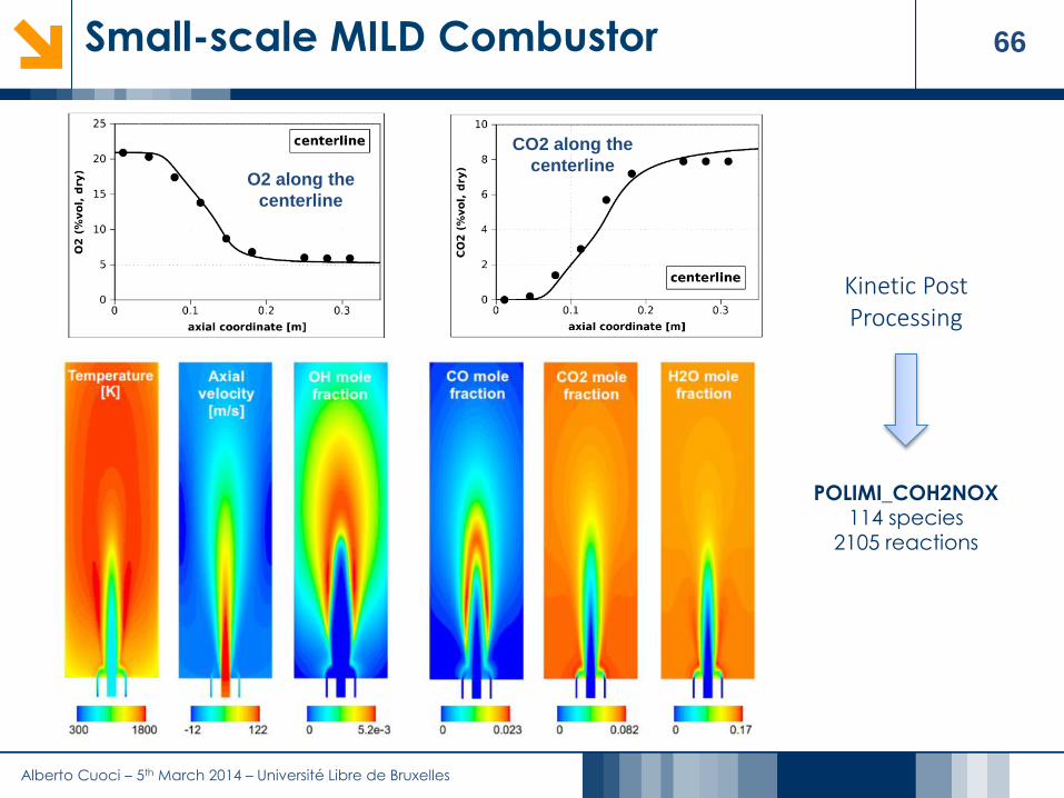
65Small-scale MILD Combustor
Combustion chamberquartz glass cylinderinternal diameter of 100 mm and length of 340 mm.
Fuel: CH4 @ 300K supplied from 16 small orifices (Ф=2mm)Oxidizer: air @ 673K supplied from a central nozzle (Ф=10mm)
3D Computational Mesh 100,000 cells
RANS SimulationK-e turbulent modelEddy Dissipation Model
Kinetic SchemeDRM22 (22 species, 111 reactions)
Verissimo, A.; Rocha, A.; Costa, M. Operational, combustion, and emission characteristics of a small-scale combustor, Energy Fuels 2011, 25(6), 2469−2480.
Alberto Cuoci – 5th March 2014 – Université Libre de Bruxelles
66Small-scale MILD Combustor
POLIMI_COH2NOX114 species
2105 reactions
Kinetic Post Processing
CO2 along the
centerlineO2 along the
centerline

Alberto Cuoci – 5th March 2014 – Université Libre de Bruxelles
67Small-scale MILD Combustor
Reactor Network:5,000 reactors
(%5 of original number of cells)
Comparison between experiments and KPP predictions
NO along the
centerline
NO radial
profile
NO radial
profile

Alberto Cuoci – 5th March 2014 – Université Libre de Bruxelles
68Outline
1. The CRECK Modeling Group @ Politecnico di Milano
2. Introduction
3. The Kinetic Post Processing (KPP) Technique for NOx Kinetic mechanisms for CFD applications
Reactor networks from CFD
Effects of temperature fluctuations on NOx formation
Solution of reactor networks
4. Applications to lab-scale and industrial flames Lab-scale flames
Industrial cases
5. Extension to other pollutants
6. Conclusions

Alberto Cuoci – 5th March 2014 – Université Libre de Bruxelles
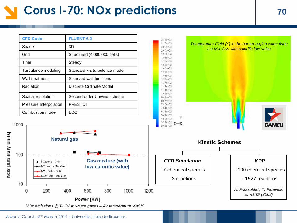
69Corus I-70: NOx predictions
Danieli Centro Combustion
Curno, Italy
Test Furnace: up to 3 MW thermal power
Fuel: gas mixtures with low calorific value
or natural gas
Gas mixture with
low calorific value
30% H2
15% CO
10% CH4
45% N2
Natural Gas
95% CH4
3% C2H6
1% N2
1% other
Burner region Burner region
Alberto Cuoci – 5th March 2014 – Université Libre de Bruxelles
70Corus I-70: NOx predictions
CFD Code FLUENT 6.2
Space 3D
Grid Structured (4,000,000 cells)
Time Steady
Turbulence modeling Standard κ-ε turbulence model
Wall treatment Standard wall functions
Radiation Discrete Ordinate Model
Spatial resolution Second-order Upwind scheme
Pressure Interpolation PRESTO!
Combustion model EDC
NOx emissions @3%O2 in waste gases – Air temperature: 490°C
Temperature Field [K] in the burner region when firing
the Mix Gas with calorific low value
CFD Simulation
- 7 chemical species
- 3 reactions
Kinetic Schemes
KPP
- 100 chemical species
- 1527 reactions
A. Frassoldati, T. Faravelli,
E. Ranzi (2003)
Natural gas
Gas mixture (with
low calorific value)

Alberto Cuoci – 5th March 2014 – Université Libre de Bruxelles
71PERM Injection System
Fuel
(Pilot line)
Fuel
(Main line)
Studied the performance of the PERM (Partial Evaporation & Rapid Mixing) injection system in a simple tubular combustor
Experimental Data From Karlsruhe University ONERA
Low P High P
Inlet Pressure [bar] 8 22
Inlet Temperature [K] 506-522 811
Air/Fuel Ratio (AFR) 18-32 25.7-28.1
Pilot/Total Fuel Ratio 15% 15%

Alberto Cuoci – 5th March 2014 – Université Libre de Bruxelles
72CFD Simulation (I)
BODY3D CFD CodeK-e turbulence model
ED-FR Combustion modelGlobal 3-step kinetic mechanism
Mesh with 80,000 cells
AFR id the air/fuel ratio

Alberto Cuoci – 5th March 2014 – Université Libre de Bruxelles
73CFD Simulation (II)
Comparison with measurements at the outlet
Low P (8 bar)
CO2temperature

Alberto Cuoci – 5th March 2014 – Université Libre de Bruxelles
74Kinetic post-processing (I)
Comparison with measurements at the outlet
Low P (8 bar)
POLIMI_NC7103 species
1500 reactions
Kinetic Post Processing
Low P (8 bar)

Alberto Cuoci – 5th March 2014 – Université Libre de Bruxelles
75Kinetic post-processing (II)
Low P (8 bar), AFR=18
Low P (8 bar), AFR=31
High temperature
Low temperature
Low P (8 bar), AFR=21.16

Alberto Cuoci – 5th March 2014 – Université Libre de Bruxelles
76The “probe effect” (I)
The model is able to capture the trends but tends to overestimate the CO emissions, especially at high temperatures. On the other hand, CO emissions predicted by the KPP are very close to the equilibrium
value at high temperatures, while the effect of finite rate kinetics is evident at lower temperatures.
CO mole fraction
NO2 mole fraction

Alberto Cuoci – 5th March 2014 – Université Libre de Bruxelles
77The “probe effect” (II)
Deviation on CO and NO2 predictions can be explained as a possible effect of the measurement technique. This problem is known in the literature.
The cooling rate of the flue gases inside the sampling probe is not fast enough to “quench” the reactivity.
Conversion of CO to CO2 and NO to NO2 occurs in the probe.
0
1
10
100
1000
10000
10 15 20 25 30 35
AFR (Air/Fuel Ratio)
CO
mo
le f
racti
on
[p
pm
]
Experimental data
BODY3D+KPP
Equilibrium
BODY3D+KPP tcooling=1E-3 [s] 0
5
10
15
20
25
30
10 15 20 25 30 35
AFR (Air/Fuel Ratio)
NO
2 [
pp
mv]
Experimental data
BODY3D+KPP
BODY3D+KPP tcooling=1E-3 [s]
qu
en
ch
ing
qu
en
ch
ing
CO mole fraction
NO2 mole fraction

Alberto Cuoci – 5th March 2014 – Université Libre de Bruxelles
78CLEAN Combustor
Pilot Run Stage Burning Full Running
Main Stage (LPP)
Pilot
ICAO 7% ICAO 30% ICAO 85-100%
Outer
liner
Inner
liner
Dilution
holes
Pilot Run Stage Burning Full Running
Main Stage (LPP)
Pilot
ICAO 7% ICAO 30% ICAO 85-100%
Pilot Run Stage Burning Full Running
Main Stage (LPP)
Pilot
ICAO 7% ICAO 30% ICAO 85-100%
Outer
liner
Inner
liner
Dilution
holes
CLEAN is an axially staged combustor equipped with:
• 18 LPP injectors (Lean Premixed Prevaporized technology)
• 18 conventional pilot injectors
0.0
0.2
0.4
0.6
0.8
1.0
-0.8 -0.6 -0.4 -0.2 0.0 0.2 0.4 0.6 0.8
Temperature Distribution Factor
No
rmali
zed
Ra
dia
lP
os
itio
n
CFD predictions
Measured data
RTDF
OTDF
RTDF
OTDF
0.0
0.2
0.4
0.6
0.8
1.0
-0.8 -0.6 -0.4 -0.2 0.0 0.2 0.4 0.6 0.8
Temperature Distribution Factor
No
rmali
zed
Ra
dia
lP
os
itio
n
CFD predictions
Measured data
RTDF
OTDF
RTDF
OTDF
Good agreement with experimental measurements of Radial
and Overall Temperature Distribution Factors at the outlet.
Alberto Cuoci – 5th March 2014 – Université Libre de Bruxelles
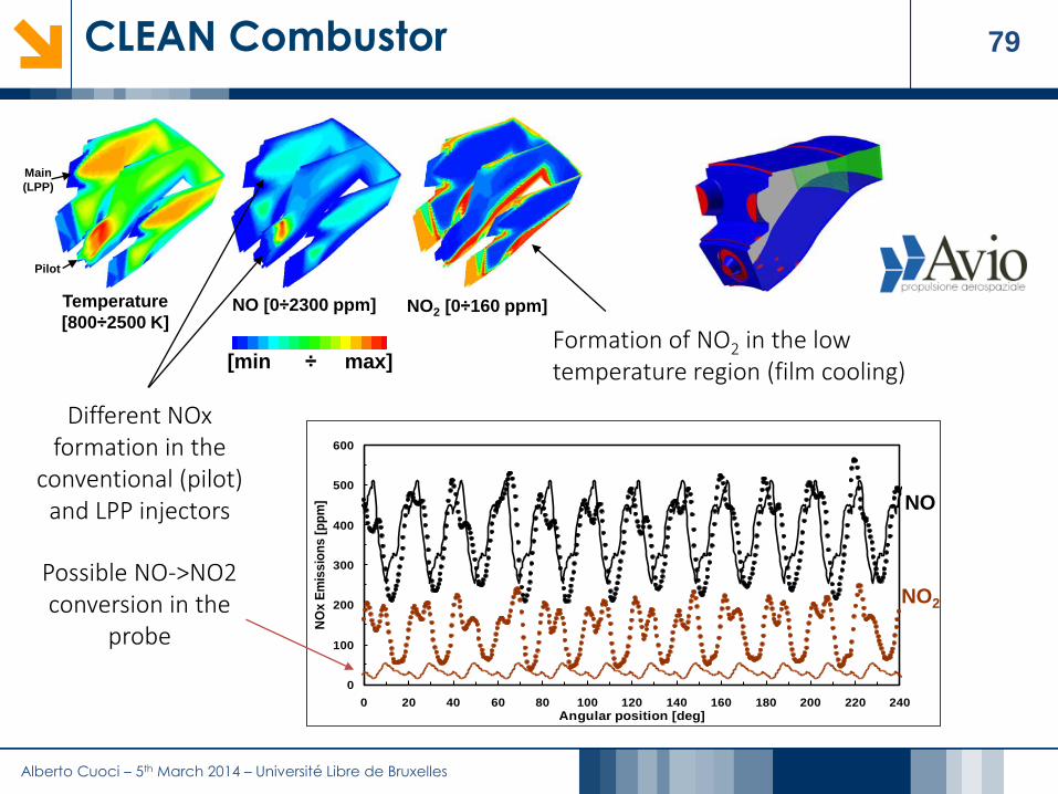
79CLEAN Combustor
[min ÷ max]
Temperature
[800÷2500 K]NO2 [0÷160 ppm]NO [0÷2300 ppm]
Main
(LPP)
Pilot
Formation of NO2 in the low temperature region (film cooling)
Different NOx formation in the
conventional (pilot) and LPP injectors
0
100
200
300
400
500
600
0 20 40 60 80 100 120 140 160 180 200 220 240
Angular position [deg]
NO
x E
mis
sio
ns
[p
pm
] NO
NO2
Possible NO->NO2 conversion in the
probe

Alberto Cuoci – 5th March 2014 – Université Libre de Bruxelles
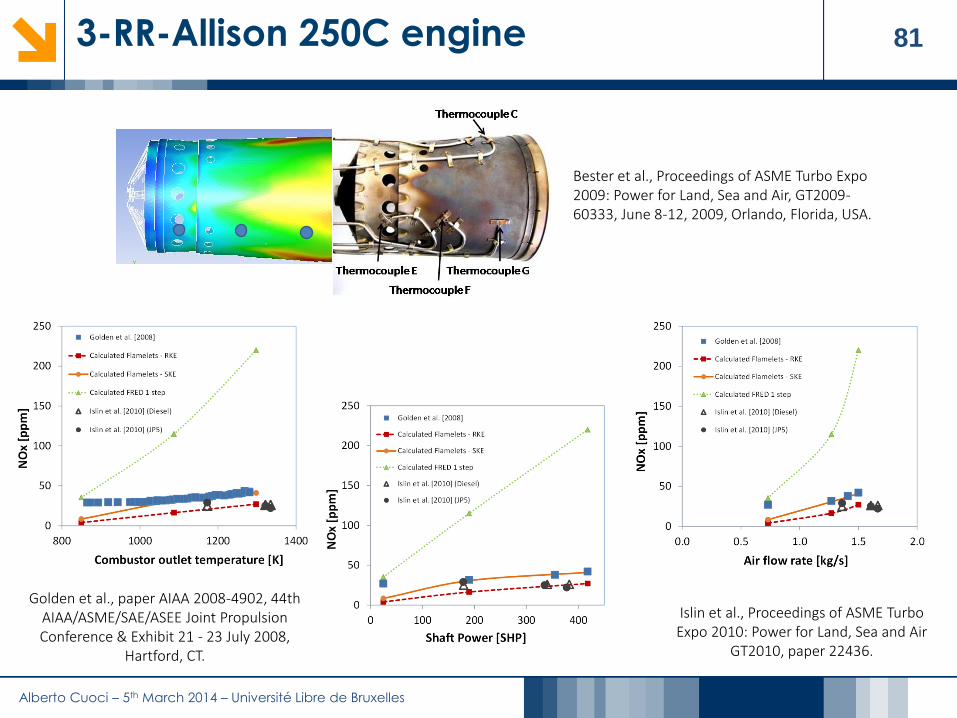
803-RR-Allison 250C engine
ROLL-ROYCE ALLISON 250 ENGINE MESH (~1,000,000 cells)
Axial velocity field (m/s)
Temperature (K)
Comparison with experimental data
Alberto Cuoci – 5th March 2014 – Université Libre de Bruxelles
813-RR-Allison 250C engine
Islin et al., Proceedings of ASME Turbo Expo 2010: Power for Land, Sea and Air
GT2010, paper 22436.
Bester et al., Proceedings of ASME Turbo Expo 2009: Power for Land, Sea and Air, GT2009-60333, June 8-12, 2009, Orlando, Florida, USA.
Golden et al., paper AIAA 2008-4902, 44th AIAA/ASME/SAE/ASEE Joint Propulsion Conference & Exhibit 21 - 23 July 2008,
Hartford, CT.

Alberto Cuoci – 5th March 2014 – Université Libre de Bruxelles
82Technip GK6 Furnace
3D Computational mesh with 500,000 cells
KPP used to evaluate effect on NOx of different burner design,
possible burner-burner interaction etc
NOx0 Max
Technip developed a parallel version of the KPP
code based on MPI

Alberto Cuoci – 5th March 2014 – Université Libre de Bruxelles
83Technip GK6 Furnace
NO2 mass fraction NO mass fraction
POLIMI_C1C3HTNOX100 species
1527 reactions
Number of Reactors:500,000
(%100 of original number of cells)
KP
P
Global Kinetic scheme6 species
3 reactions
Eddy Dissipation Concept Model
CF
D

Alberto Cuoci – 5th March 2014 – Université Libre de Bruxelles
84IFRF Furnace (OxyFLAM2)
Experimental data
velocity, main species and temperature profiles
inside the furnace at several axial locationsThermal power: 0.78 MW
Furnace dimensions: 3750 x 1050 x 1050 mm
Lallemant N., Dugué J., Weber R.
IFRF Document F85/y/4 (1996)

Alberto Cuoci – 5th March 2014 – Université Libre de Bruxelles
85IFRF Furnace (OxyFLAM2)
POLIMI_C1C3HTNOX100 species
1527 reactions
Number of Reactors:5,000
(%10 of original number of cells)
KPP
Skeletal Kinetic Scheme33 species
152 reactions
Eddy Dissipation Concept Model
CFD

Alberto Cuoci – 5th March 2014 – Université Libre de Bruxelles
86IFRF Furnace (OxyFLAM2)
PolimiC1C3HT + NOX
100 species, 1530 reactions
http://creckmodeling.chem.polimi.it
Ranzi E., Faravelli T.,Frassoldati A., Granata S., , Industrial and Engineering Chemistry Research, 44 (44), 5170-5183 (2005).

Alberto Cuoci – 5th March 2014 – Université Libre de Bruxelles
87The FLOX® Burner
A. Parente, A. Cuoci, C. Galletti, A. Frassoldati, T. Faravelli, L. Tognotti, NO formation in flameless combustion: comparison of different modeling approaches, European Combustion Meeting 2009 14-17 April 2009 - Vienna, Austria
rad
ian
t tu
be
flam
e t
ub
e
fuel inlet
air inlet
window
FA [s] T [K] |V| [m/s]
20 30 40 50 60 70 8020
30
40
50
60
70
80
NO [ppm] - Exp.
NO
[ppm
] -
Num
.
Mesh 9,500 cells
FA [s] T [K] |V| [m/s]
20 30 40 50 60 70 8020
30
40
50
60
70
80
NO [ppm] - Exp.
NO
[ppm
] -
Num
.
Comparison between experiments
and simulation
NO [ppm] – Exp.
NO
[p
pm
] –
Nu
me
ric
al
Alberto Cuoci – 5th March 2014 – Université Libre de Bruxelles
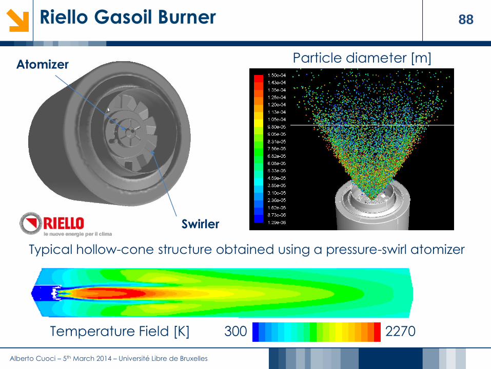
88Riello Gasoil Burner
Temperature Field [K] 300 2270
Typical hollow-cone structure obtained using a pressure-swirl atomizer
Particle diameter [m]Atomizer
Swirler

Alberto Cuoci – 5th March 2014 – Université Libre de Bruxelles
89Riello Gasoil Burner
Alberto Cuoci – 5th March 2014 – Université Libre de Bruxelles
90Riello Gasoil Burner
0
10
20
30
40
50
60
1 1.1 1.2 1.3 1.4
Air Excess
NO
x e
mis
sio
ns [
pp
m]
1 MW
0.8 MW
0.6 MW0.35 MW
0.22 MW
0
10
20
30
40
50
60
1 1.1 1.2 1.3 1.4
Air Excess
NO
x e
mis
sio
ns [
pp
m]
1 MW
0.8 MW
0.6 MW0.35 MW
0.22 MW
New
3 MW
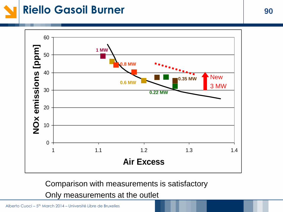
Comparison with measurements is satisfactory
Only measurements at the outlet

Alberto Cuoci – 5th March 2014 – Université Libre de Bruxelles
91Outline
1. The CRECK Modeling Group @ Politecnico di Milano
2. Introduction
3. The Kinetic Post Processing (KPP) Technique for NOx Kinetic mechanisms for CFD applications
Reactor networks from CFD
Effects of temperature fluctuations on NOx formation
Solution of reactor networks
4. Applications to lab-scale and industrial flames Lab-scale flames
Industrial cases
5. Extension to other pollutants
6. Conclusions

Alberto Cuoci – 5th March 2014 – Université Libre de Bruxelles
92Sandia Bluff-Body Flame
NO
Mass
Fra
ctio
n
CO
Mass
Fra
ctio
n
NO
Mass
Fra
ctio
n
NO
Mass
Fra
ctio
n
ba
c d
NO
Mass
Fra
ctio
n
CO
Mass
Fra
ctio
n
NO
Mass
Fra
ctio
n
NO
Mass
Fra
ctio
n
ba
c dradial coordinate [m] radial coordinate [m]
NO
Mass
Fra
ctio
n
CO
Mass
Fra
ctio
n
NO
Mass
Fra
ctio
n
NO
Mass
Fra
ctio
n
ba
c d
NO
Mass
Fra
ctio
n
CO
Mass
Fra
ctio
n
NO
Mass
Fra
ctio
n
NO
Mass
Fra
ctio
n
ba
c d
without prompt NOx
T[K] CO NO HCNNO2C2H2 CH2OC2H6CH4T[K] CO NO HCNNO2C2H2 CH2OC2H6CH4T[K] CO NO HCNNO2C2H2 CH2OC2H6CH4T[K] CO NO HCNNO2C2H2 CH2OC2H6CH4

Alberto Cuoci – 5th March 2014 – Université Libre de Bruxelles
93Local temperature unbalance
Local temperature unbalances in K
The average temperature unbalance is 0.27 K, with a standard deviation of 5.43 K
The weak influence of the minor species on the temperature fields was checked through an energy analysis of the reactor network. For each reactor, energy unbalances were calculated:
The overall energy unbalance due to the post-processing was evaluated as the difference. Then, the unbalance in terms of temperature was calculated as:
CFD in out CFDH H H
KPP in out KPPH H H
KPP CFD
P
H HT
C m
Alberto Cuoci – 5th March 2014 – Université Libre de Bruxelles
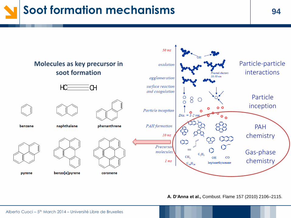
94Soot formation mechanisms
Particle-particle interactions
Particle inception
Gas-phase chemistry
PAHchemistry
Molecules as key precursor in soot formation
• Oligomers of aromatic compounds (OAC)
A. D‘Anna et al., Combust. Flame 157 (2010) 2106–2115.
CH CH

Alberto Cuoci – 5th March 2014 – Université Libre de Bruxelles
95The Discrete Sectional Method
Discrete sectional method: Large PAHs and soot particles with diameters of up to ~60 nm are defined as classes with increasing molecular mass.
Each class is represented by a combination of lumped pseudo-species (BINs), each with an assigned H/C.
The first BIN is the species with 20 carbon atoms and mass of about 250 amu, which is the corannulene. The first particle of soot is considered of about 3000 amu, which is the BIN5.

Alberto Cuoci – 5th March 2014 – Université Libre de Bruxelles
96Towards soot: from acetylene to PAHs
7.2e-6
0
Acetylene Benzene Naphthalene
Phenanthrene Pyrene Indene
0
1.4e-2
0
1.6e-7
0
7.2e-8
0
3.1e-6
0
3.4e-4
Alberto Cuoci – 5th March 2014 – Université Libre de Bruxelles
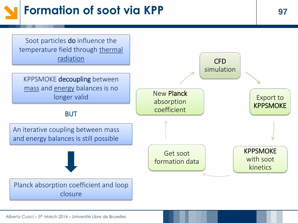
97Formation of soot via KPP
Soot particles do influence the temperature field through thermal
radiation
BUT
An iterative coupling between mass and energy balances is still possible
KPPSMOKE decoupling between mass and energy balances is no
longer valid
Planck absorption coefficient and loop closure
CFD simulation
Export to KPPSMOKE
KPPSMOKEwith sootkinetics
Get sootformation data
New Planckabsorptioncoefficient

Alberto Cuoci – 5th March 2014 – Université Libre de Bruxelles
98Outline
1. The CRECK Modeling Group @ Politecnico di Milano
2. Introduction
3. The Kinetic Post Processing (KPP) Technique for NOx Kinetic mechanisms for CFD applications
Reactor networks from CFD
Effects of temperature fluctuations on NOx formation
Solution of reactor networks
4. Applications to lab-scale and industrial flames Lab-scale flames
Industrial cases
5. Extension to other pollutants
6. Conclusions

Alberto Cuoci – 5th March 2014 – Université Libre de Bruxelles
99References
Papers on Kinetic Post Processing of NOx (I)
Monaghan R., Tahir R., Bourque G., Gordon R., Cuoci A., Faravelli T., Frassoldati A., Curran H., "Detailed emissions prediction for a turbulent swirling non-premixed flame", (2014) Energy & Fuels, 28 (2), pp 1470-1488, DOI: 10.1021/ef402057w
Stagni A., Cuoci A., Frassoldati A., Faravelli T., Ranzi E., "A fully coupled, parallel approach for the post processing of CFD data through reactor network analysis", (2014) Computers & Chemical Engineering, 60, pp 197-212, DOI: http://dx.doi.org/10.1016/j.compchemeng.2013.09.002
Cuoci, A., Frassoldati, A., Stagni, A., Faravelli, T., Ranzi, E., Buzzi-Ferraris, G., Numerical modeling of NOx formation in turbulent flames using a kinetic post-processing technique (2013) Energy and Fuels, 27 (2), pp. 1104-1122, DOI: 10.1021/ef3016987
Shabanian, S.R., Medwell, P.R., Rahimi, M., Frassoldati, A., Cuoci, A., Kinetic and fluid dynamic modeling of ethylene jet flames in diluted and heated oxidant stream combustion conditions (2013) Applied Thermal Engineering, 52 (2), pp. 538-554 DOI: 10.1016/j.applthermaleng.2012.12.024
Monaghan, R.F.D., Tahir, R., Cuoci, A., Bourque, G., Furi, M., Gordon, R.L., Faravelli, T., Frassoldati, A., Curran, H.J., Detailed multi-dimensional study of pollutant formation in a methane diffusion flame (2012) Energy and Fuels, 26 (3), pp. 1598-1611, DOI: 10.1021/ef201853k

Alberto Cuoci – 5th March 2014 – Université Libre de Bruxelles
100References
Papers on Kinetic Post Processing of NOx (II)
Frassoldati, A., Cuoci, A., Faravelli, T., Ranzi, E., Colantuoni, S., Di Martino, P., Cinque, G., Kern, M., Marinov, S., Zarzalis, N., Da Costa, I., Guin, C., Fluid dynamics and detailed kinetic modeling of pollutant emissions from lean combustion systems (2010) Proceedings of the ASME Turbo Expo, 2 (PARTS A AND B), pp. 451-459, DOI: 10.1115/GT2010-22551
Frassoldati, A., Sharma, P., Cuoci, A., Faravelli, T., Ranzi, E., Kinetic and fluid dynamics modeling of methane/hydrogen jet flames in diluted coflow (2010) Applied Thermal Engineering, 30 (4), pp. 376-383, DOI: 10.1016/j.applthermaleng.2009.10.001
D. Manca, G. Buzzi-Ferraris, A. Cuoci, A. Frassoldati (2009). The solution of very large non-linearalgebraic systems. COMPUTERS & CHEMICAL ENGINEERING, vol. 33, p. 1727-1734, ISSN:0098-1354, doi: 10.1016/j.compchemeng.2009.04.010
A. CUOCI, A. FRASSOLDATI, BUZZI FERRARIS G, T. FARAVELLI, RANZI E.M. (2007). The ignition,combustion and flame structure of carbon monoxide/hydrogen mixtures. Note 2: Fluid dynamics andkinetic aspects of syngas combustion. INTERNATIONAL JOURNAL OF HYDROGEN ENERGY, vol. 32, p.3486-3500, ISSN: 0360-3199, doi: 10.1016/j.ijhydene.2007.02.026

Alberto Cuoci – 5th March 2014 – Université Libre de Bruxelles
101References
Other
Stagni A., Cuoci A., Frassoldati A., Faravelli T., Ranzi E., "Lumping and reduction of detailed kinetic schemes: an effective coupling", Industrial & Engineering Chemistry Research, Accepted, In press (2014), DOI: 10.1021/ie403272f
Ranzi, E., Frassoldati, A., Grana, R., Cuoci, A., Faravelli, T., Kelley, A.P., Law, C.K.. Hierarchical and comparative kinetic modeling of laminar flame speeds of hydrocarbon and oxygenated fuels (2012) Progress in Energy and Combustion Science, 38 (4), pp. 468-501, DOI: 10.1016/j.pecs.2012.03.004
Frassoldati, A., Cuoci, A., Faravelli, T., Niemann, U., Ranzi, E., Seiser, R., Seshadri, K., An experimental and kinetic modeling study of n-propanol and iso-propanol combustion (2010) Combustion and Flame, 157 (1), pp. 2-16, DOI: 10.1016/j.combustflame.2009.09.002