numerical simulation of sloshing phenomena in cubic tank...
TRANSCRIPT

Hindawi Publishing CorporationJournal of Applied MathematicsVolume 2012, Article ID 245702, 21 pagesdoi:10.1155/2012/245702
Research ArticleNumerical Simulation of Sloshing Phenomena inCubic Tank with Multiple Baffles
Mi-An Xue,1, 2 Jinhai Zheng,1, 2 and Pengzhi Lin3
1 State Key Laboratory of Hydrology-Water Resources and Hydraulic Engineering,Hohai University, Nanjing 210098, China
2 College of Harbour, Coastal and Offshore Engineering, Hohai University, Nanjing 210098, China3 State Key Laboratory of Hydraulics and Mountain River Engineering, Sichuan University,Chengdu 610065, China
Correspondence should be addressed to Jinhai Zheng, [email protected] Pengzhi Lin, [email protected]
Received 20 January 2012; Revised 17 April 2012; Accepted 30 April 2012
Academic Editor: Carl M. Larsen
Copyright q 2012 Mi-An Xue et al. This is an open access article distributed under the CreativeCommons Attribution License, which permits unrestricted use, distribution, and reproduction inany medium, provided the original work is properly cited.
A two-phase fluid flow model solving Navier-Stokes equations was employed in this paper toinvestigate liquid sloshing phenomena in cubic tank with horizontal baffle, perforated verticalbaffle, and their combinatorial configurations under the harmonic motion excitation. Laboratoryexperiment of liquid sloshing in cubic tank with perforated vertical baffle was carried out to vali-date the present numerical model. Fairly good agreements were obtained from the comparisonsbetween the present numerical results and the present experimental data, available numerical data.Liquid sloshing in cubic tank with multiple baffles was investigated numerically in detail underdifferent external excitation frequencies. Power spectrum of the time series of free surface elevationwas presented with the aid of fast Fourier transform technique. The dynamic impact pressuresacting on the normal and parallel sidewalls were discussed in detail.
1. Introduction
The effect of severe sloshingmotion on global seagoing vessels is an important factor in safetydesign of such containers. The violent motion of fuel or liquid cargo in tanks may result insevere sloshing loads on the containment system and supporting structure. It is importantto quantify the effects of this sloshing on the system for design consideration. Even simplebaffles reduce sloshing effects by dissipating kinetic energy due to the production of vorticesinto the fluid; their exact shapes and positions need to be designed with the use of numericalmodel simulation or physical testing. Nonetheless, the dampingmechanisms of baffle are stillnot fully understood. Moreover, liquid sloshing in containers is an important phenomenon

2 Journal of Applied Mathematics
of great practical application with regard to the safety of space vehicles, storage tanks, roadvehicle tanks, ships, and elevated water towers under ground motion and remains of greatconcern to aerospace, civil, nuclear engineers, physicists, designers of road tankers and shiptankers, and mathematicians [1]. The studies of liquid sloshing in a tank with baffles are stillvery necessary.
Liquid sloshing phenomenon has been investigated extensively using variousnumerical model [2] and experimental setup in the past few decades. Faltinsen [3] developeda boundary element method (BEM) model to study liquid sloshing problems. Koh et al.[4] developed a coupled BEM-FEM for the dynamic analysis of rectangular liquid storagetanks including free surface sloshing motion. Chen and Chiang [5] analyzed the interactioneffect between the fully nonlinear sloshing fluid and the floating tank associatedwith coupledsurge, heave and pitch motions. Dodge [6] offered more valuable results on lateral sloshingin moving containers in spacecraft applications. Forbes [7] studied the motion of an idealfluid in a rectangular tank under horizontal sinusoidal periodic forcing excitation.
Fluid motion in partially filled tanks is prone to have a big impact on the forces actingon the tank walls when the frequency of tank-forced motion is close to a natural frequencyof fluids inside the tank or the external excitation amplitude is very large. The damping ofsloshing is therefore a key issue in liquid-filled tanker design. Keulegan and Parkinson [8]studied the inertia and drag coefficient of cylinders and plates in an oscillating fluid. Miles [9]analyzed the damping effects of ring baffle and obtained an analytical solution for dampingratio in terms of tank dimensions and sloshing height amplitude for circular-cylindrical tankswhen the liquid height is considerably greater than the tank radius. Armenio and La Rocca[10] analyzed sloshing of water in rectangular open tanks and observed that the presence ofa vertical baffle at the middle of the tank dramatically changed the sloshing response. Kim[11] simulated liquid sloshing in 2D and 3D liquid containers with and without baffle usingfinite difference method (FDM). Akyildiz and Celebi [12] investigated pressure distributionin a rigid rectangular tank due to large amplitude liquid sloshing. In their studies, differentcases including baffled and unbaffled tanks with different filling levels were computed in thevicinity of the natural frequency. Celebi and Akyildiz [13] studied a nonlinear sloshing insidea partially filled rectangular tank with and without baffle. Akyildiz and Unal [14] conductedan experimental study on pressure variations and 3D effects due to liquid sloshing in a baffledtank under pitch excitation. Cho et al. [15] investigated the effects of baffle on liquid sloshingin a 2D baffled tank subjected to forced excitation by using finite element method (FEM).Biswal et al. [16] studied the influence of annular baffle on nonlinear sloshing in both cylindri-cal and rectangular tank using FEM. The results indicate that the baffle has greater influenceon the slosh frequencies of liquid when placed near to the liquid free surface, and the influ-ence is gradually reduced when it is moved towards the bottom of the tank.
Baffle with orifice can be found in some contemporary road tankers carrying fuel oilsor liquefied natural gas (LNG). This kind of baffle can allow the lower surface liquid to passthrough, thus attenuating the impact forces on the baffle. Younes et al. [17] conducted anexperimental study of the hydrodynamic damping provided by using vertical baffles withorifice in partially filled rectangular tanks; they pointed out that the size, location, number,and drilling holes of the vertical baffle significantly influence the hydrodynamic damping.Panigrahy et al. [18] developed a slosh experimental setup with a degree of freedom (DOF)of horizontal motion to estimate pressure distribution on tank walls and surface elevationvariation in a tank with drilled orifice baffle. Eswaran et al. [19] numerically investigated theeffects of baffles with different shapes and arrangements on a partially filled cubic tank usingthe automatic dynamic incremental nonlinear analysis (ADINA) software.

Journal of Applied Mathematics 3
In the present study, liquid sloshing in cubic tank with horizontal baffle, perforatedvertical baffle and their combination are investigated numerically to explore the effects of baf-fle with different shapes and arrangements on reducing liquid sloshing. A virtual boundaryforce (VBF) method [20] by using the idea of applying momentum forces, which stems fromthe immersed boundary (IB) method [21] but can handle the surface-piercing structures, isadopted and combined with the volume-of-fluid (VOF) method in this study to investigateliquid sloshing in three-dimensional (3D) rectangular tank with internal baffles. A two-phasefluid flow model is employed to solve the spatially averaged Navier-Stokes equations in anoninertial reference frame. The resulting pressure Poisson equation revised by VBF methodis solved by the two-step projection method with the aid of Bi-CGSTAB technique, and thelarge-eddy simulation (LES) technique is used for turbulence modeling.
2. Mathematical Model and Numerical Approach
In this study, an in-house code [22] is employed for all numerical predictions. The three-dimensional incompressible liquid sloshing motions in a tank are governed by the spatiallyaveraged Navier-Stokes (SANS) equations, continuity equation and transportation equationof density. The Smagorinsky subgrid-scale (SGS) turbulence model is applied, so the SANSequations can be written in tensor form as follows:
∂ui
∂xi= 0, (2.1)
∂ui
∂t+∂uiuj
∂xj= −1
ρ
∂p
∂xi+
∂
∂xj
[(ν + νt)
(∂ui
∂xj+∂uj
∂xi
)]+ fi, (2.2)
∂ρ
∂t+ ui
∂ρ
∂xi= 0, (2.3)
where i,j = 1, 2, 3 for three-dimensional flows, ui denotes the ith filtered velocity component,ρ is the liquid density, ν is the kinematic viscosity, p is the filtered pressure, and the fi isthe external body force. Once the rate of the strain tensor σij = (∂ui/∂xj + ∂uj/∂xi)/2 isdefined in this model, the molecular viscous stress tensor τij = 2ρνσij is obtained here. Thesymbol “−” denotes spatially averaged and can be dropped herein for simplicity. Especiallythe stress Rij = 2ρνtσij is modeled by the SGS turbulence model from the concept of LES,
where νt = l2s
√2σijσij is the eddy viscosity and ls is the characteristic length scale which is
proportional to the filter width 3√ΔxΔyΔz through the Smagorinsky coefficient cs = 0.15 [23].
In LES, the larger 3D unsteady turbulent motions are directly represented, whereas the effectsof the smaller-scale motions are modeled. LES can be therefore expected to be more accurateand reliable than Reynolds-stress models for flows in which large-scale unsteadiness is signi-ficant.
The vector form of external body force fi is as follows [24]:
⇀
f=⇀g −d
⇀
Udt
− d⇀
θdt
×(⇀r − ⇀
R)− 2
⇀
θ ×d(⇀r − ⇀
R)
dt− ⇀
θ ×[⇀
θ ×(⇀r − ⇀
R)]
, (2.4)

4 Journal of Applied Mathematics
where⇀g ,
⇀
U, and⇀
θ are the gravitational acceleration, translational and rotational velocity of
the noninertial coordinate, respectively;⇀r and
⇀
R are the position vector of the consideredpoint and rotational motion origin O. The second term of the right-hand side is the trans-lational inertia, while the third, fourth, and fifth terms are due to the rotational motion, whichare referred to as the angular acceleration, Coriolis force, and Centrifugal force, respectively.
In order to model the internal baffle, the VBF method is adopted here. In the VBFmethod, an additional virtual boundary force (FVBF)i, which is to replace the actual reactionforce and is only nonzero on the solid surface, is applied in the SANS equations. Thedefinition of the (FVBF)i is as follows:
(FVBF)i =
⎧⎪⎨⎪⎩
un+1i − un+1
i
Δt+
1ρn
∂pn+1
∂xi− fi virtual boundary
0 elsewhere.(2.5)
The detailed numerical implementations to determine the (FVBF)i can be found in our pre-vious works [20, 25].
The VOF interface tracking method is used to track the free surface. By introducing aVOF function F,
F =ρ − ρg
ρl − ρg, (2.6)
where ρg is density of gas and ρl is density of liquid. Equation (2.3) becomes
∂F
∂t+ ui
∂F
∂xi= 0, (2.7)
where F represents the volumetric fraction between the gas and liquid, which equals to0 in gas and 1 in liquid. In the VOF method, the second-order piecewise linear interfacecalculation is used to reconstruct the interface and to determine the VOF fluxes; the normalvector of the interface in each grid is calculated using Youngs’ least squares method [26]. Thedetails of the numerical procedures can be found in Liu [27].
In the study, an FDM is applied to solve the governing equations. Tank volume isdiscretized into the Cartesian staggered grid system, as shown in Figure 1. The velocity com-ponents are defined at the centers of cell boundaries; pressure and VOF function is calculatedat the center of the cell. The forward time difference method is used to discretize the timederivative, and the central difference method is employed to discretize the pressure gradientterms. The convection terms are discretized by the combination of the central differencemethod and upwind method; taking the term (∂u/∂x)i+1/2,j,k, for example,
(∂u
∂x
)i+1/2,j,k
=
{[1 + α sgn
(ui+1/2,j,k
)]Δxi+1(∂u/∂x)i,j,k +
[1 − α sgn
(ui+1/2,j,k
)]Δxi(∂u/∂x)i+1,j,k
}Δxα
,
(2.8)

Journal of Applied Mathematics 5
∆xi
∆yj
∆zk
ui+1/2,j,kui−1/2,j,k
wi,j,k+1/2
νi,j +1/2,k
νi,j −1/2,k
wi,j,k−1/2
Pi,j,k
Fi,j,k
Figure 1: The definition of physical quantity in the Cartesian staggered grid.
where Δxα = Δxi+1 + Δxi + α sgn(ui+1/2,j,k)(Δxi+1 − Δxi), the coefficient α is weight factorbetween the upwind scheme and the central difference scheme. The finite difference formbecomes the central difference when α = 0; the finite difference form becomes the upwindscheme when α = 1. In this study, the value of the coefficient α = 0.3 is used in the followingsimulations. Two-step projection method is employed here to solve the SANS equations; thedetails of numerical procedure are similar to that described in Xue and Lin [25]. In the initialnumerical simulation, all the liquid was assumed to be at rest. The boundary conditions ofno-slip velocity and zero normal pressure gradients are applied on the liquid-solid interfaces.
3. Model Validations
3.1. 2D Sloshing in Tank with Horizontal Baffle under Surge Excitation
Baffles are widely used as slosh suppression devices in the liquid storage containers. How-ever, baffle damping effectiveness depends upon dimension and orientation of the baffleinstalled into a tank. Biswal et al. [16] investigated the effects of a horizontal baffle on theslosh response by varying its position and length via solving Laplace equation using a mixedEulerian-Langrangian FEM. In their study, three different horizontal baffles in length will beselected here to compare with the present numerical results. The length of the rectangulartank is 1.0m, and the liquid depth in the tank is 0.5m. The tank is subjected to sinusoidalhorizontal acceleration: x = −aω2 sinωt, where excitation amplitude a = 0.002m andexcitation frequency ω = 5.29 rad/s. The ratio W/L of horizontal baffle length versus tanklength is taken as 0.4, 0.6, and 0.8, respectively. The baffle is located at a depth of b = 0.8hfrom the initial free surface and on the left boundary of the tank, as shown in Figure 2. Thebaffle is 0.005m in thickness, which is made of PVC and is assumed to be rigid. The employedgrid system in our simulation has 50 uniform horizontal meshes with Δx = 0.02m and 63nonuniform vertical meshes with 20 grids of the minimum mesh size Δz = 0.006m beingdeployed in the vicinity of the free liquid surface.
Comparisons of the time history of free surface sloshing response at the right wallof the tank between the present numerical results and the numerical data of Biswal et al. areplotted in Figure 3 for variousW/L ratios. Good agreements are obtained. It is observed fromFigure 3 that the nonlinear liquid sloshing amplitude at the right tank wall decreases with

6 Journal of Applied Mathematics
b
Wh
L
Figure 2: Rectangular tank with a horizontal baffle.
0 3 6 9 12 15
00.040.08
−0.04−0.08
Time (s)
W/L = 0.4
Free
sur
face
elev
atio
n(m
)
(a)
0 3 6 9 12 15Time (s)
00.040.08
−0.04−0.08
W/L = 0.6
Free
sur
face
elev
atio
n(m
)
(b)
0 3 6 9 12 15
Time (s)
00.040.08
−0.04−0.08
W/L = 0.8
Free
sur
face
elev
atio
n(m
)
(c)
Figure 3: Comparisons of the time history of free surface elevation at the right wall of the baffled tankbetween the present numerical results (solid line) and the numerical data of Biswal et al. [16] (circle).
the increase in the W/L ratio. One of possible damping mechanisms is that the increasingbaffle surface area suppresses the vertical velocity of more slosh fluids, as shown in Figure 4.
3.2. 3D Sloshing in Tank with Perforated Vertical Baffle underSurge Excitation
In this section, an experiment of liquid sloshing in cubic tank with perforated vertical baffleunder different excitation frequencies was carried out in State Key Laboratory of Hydraulicsand Mountain River Engineering at Sichuan University in China. The cubic Perspex tank ofinterior length 570mm, width 310mm, and height 700mm was fixed on a shaking table thatcould move horizontally on linear bearings. Oscillatory movement of the shaking table wasdriven by an irregular wave-maker system [25], which can produce all kinds of harmonic and

Journal of Applied Mathematics 7
t = 14.3 s
(a)
t = 14.6 s
(b)
t = 14.3 s
(c)
t = 14.6 s
(d)
0.2 m/s
t = 14.3 s
(e)
t = 14.6 s
0.2 m/s
(f)
Figure 4: Velocity fields of liquid sloshing in a tank with different horizontal baffle in length.
random motion such as cosine function and JONSWAP spectra. In this study, only the purecosine motion of the wave-maker was used; the available random motion would be used forfuture experimental investigations on nonlinear liquid sloshing using this apparatus.
The experimental apparatus and baffle configuration is shown in Figure 5. Three wavegauge sensors are employed to record the free surface elevation with time. Two pressuretransducers are used to obtain the slosh-induced impact pressure acting on the right tankwall. The vertical baffle with square orifice with 250mm in height, 310mm in width, and6mm in thickness is mounted on the center of bottom of the tank. The square orifice of length80mm is made of rigid Perspex, whose center locates at 35mm on the central upper part ofthe vertical baffle. Theworking fluid that was used in the experiment reported here waswater

8 Journal of Applied Mathematics
Figure 5: Schematic diagram of wave gauges, pressure transducers and slosh suppression baffle arrange-ment.
at room temperature. The water depth was 280mm, so the lowest natural frequency is ω0 =7.0247 rad/s according to the dispersion equation ω2
n = kg tanh kh, where k = (2n + 1)π/L,L is tank length, h is water depth, and n is the mode number. The tank motion is the surgeoscillations along the x-axis, which follows the cosine function given as x = −a cosωt, wherea = 15mm and ω = 0.5ω0 are the external excitation amplitude and frequency, respectively.
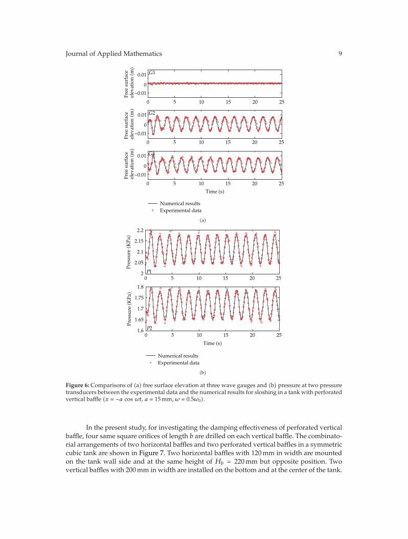
Experiment and numerical simulation of liquid sloshing in cubic tank with perforatedvertical baffle are synchronously considered here. In the simulation, the 3D grid system has114 × 62 uniform horizontal meshes with the mesh size Δx = Δy = 5mm and 70 nonuniformvertical meshes with 20 grids being arranged near the free surface in which the minimummesh size isΔz = 2mm. Figure 6 shows the comparisons of the free surface elevation at threewave gauges and the pressure at two pressure transducers between the experimental dataand the numerical simulation results. Fairly good agreements are obtained at all measure-ment points, indicating that the present model is an accurate tool in investigating the liquidsloshing phenomenon in a tank with baffles.
4. Numerical Simulation of Liquid Sloshing inCubic Tank with Multiple Baffles
4.1. Problem Description
Slosh suppression inmoving liquid storage containers is considered to be one of themajor keyissues in engineering designs. One approach to slosh suppression of such systems partiallyfilled by liquids is through energy dissipation using a partition or baffle. The conventionalhorizontal baffles or vertical baffles are already in use for slosh suppression of liquefiednatural gas (LNG) containments. The nonconventional vertical baffle perforation may offersubstantial advantages in terms of both increased damping effectiveness and reduced baffleweight. However, the damping provided by the perfected baffle depends upon the orificesize, number, location and excitation frequency, and so forth.
Journal of Applied Mathematics 9
0 5 10 15 20 25
Time (s)
0 5 10 15 20 25
0 5 10 15 20 25
Numerical resultsExperimental data
G2
G3
G1
−0.01
0
0.01
Free
sur
face
elev
atio
n(m
)Fr
ee s
urfa
ceel
evat
ion(m
)Fr
ee s
urfa
ceel
evat
ion(m
)
−0.01
0
0.01
−0.01
0
0.01
(a)
0 5 10 15 20 25
Time (s)
0 5 10 15 20 25
P2
P1
1.6
1.65
1.7
1.75
1.8
2
2.05
2.1
2.15
2.2
Pres
sure
(KPa
)Pr
essu
re(K
Pa)
Numerical resultsExperimental data
(b)
Figure 6: Comparisons of (a) free surface elevation at three wave gauges and (b) pressure at two pressuretransducers between the experimental data and the numerical results for sloshing in a tank with perforatedvertical baffle (x = −a cos ωt, a = 15mm, ω = 0.5ω0).
In the present study, for investigating the damping effectiveness of perforated verticalbaffle, four same square orifices of length b are drilled on each vertical baffle. The combinato-rial arrangements of two horizontal baffles and two perforated vertical baffles in a symmetriccubic tank are shown in Figure 7. Two horizontal baffles with 120mm in width are mountedon the tank wall side and at the same height of Hb = 220mm but opposite position. Twovertical baffles with 200mm in width are installed on the bottom and at the center of the tank.

10 Journal of Applied Mathematics
G3
G2
G1
5
5
Motion direction
Unit: mm
h
b
Hb
100
100
50P1
P2
P3
P4
P5
P6
Figure 7: Schematic of liquid sloshing in cubic tank with horizontal baffles and orifice vertical baffles.
The square orifice length b is selected to be equal to 0mm, 40mm, and 80mm, respectively.Three numerical wave gauges, which are located at the center, 5mm near the left and rightboundary of the tank, are used to record the free surface elevation with time. Six numericalpressure gauges are used to obtain the slosh-induced impact pressure acting on the sidewallsnormal and parallel to the motion direction of the tank. For cubic tank, the (n,m)wavemodeshave the corresponding natural frequency that is determined by the dispersion equation:
ω2mn =
√√√√(mgπ
Lx
)2
+
(ngπ
Ly
)2
tanh
√√√√(mπh
Lx
)2
+
(nπh
Ly
)2
(m,n = 0, 1, 2, . . .). (4.1)
The tank dimension is Lx = Ly = 600mm, and the water depth is h = 300mm, so that 50%of the tank is filled with water. The length and width of the tank was chosen to be equal toobtain the symmetric behavior of the cubic tank in this study. So, the lowest natural frequencyisω10 = ω01 = 6.8636 rad/s due to the symmetry of the cubic tank. The computational domainis discretized by 120 × 60 uniform meshes with the mesh size Δx = 5mm and Δy = 10mmin the horizontal plane and 100 nonuniform vertical meshes with 20 meshes being arrangednear the free surface, where the minimum mesh size is Δz = 3mm. The horizontal excitationvelocity of the tank follows cosine function, that is, u = −A cosωt for t ≥ 0, where A = aω isthe velocity amplitude with a = 5mm being the displacement amplitude andω is the angularfrequency of the excitation. In the following simulations, the excitation frequency ω wouldbe chosen as π and 6.8636 rad/s, respectively.

Journal of Applied Mathematics 11
4.2. Free Surface Elevation and Power Spectrum
In this section, several numerical experiments are performed in the same cubic tank forinvestigating the effect of combinatorial baffles on reducing liquid sloshing. In the simulationof ω = π rad/s being away from the lowest natural frequency of liquid-tank system, thenumerical results of free surface elevation η at three wave gauges are plotted in Figure 8 forliquid sloshing in cubic tank with different baffle arrangements. It is shown that the effective-ness of different combinatorial baffles on reducing liquid sloshing amplitude is no apparentdifference and slight when the external excitation frequency is away from the resonant fre-quency. However, the natural frequency has been shifted due to the presence of the baffles.The quantitative data are clearer in the power spectrum of the time series of the free surfaceelevation at wave gauge G1. The input data of 30 s with sampling interval 0.01 s were used toobtain the power spectrum with the aid of the fast Fourier transform (FFT) technique.
Figure 9 shows the power spectrum for liquid sloshing in a tank without baffle, withvertical baffles and horizontal baffles, with small orifice baffles and horizontal baffles, andwith big orifice baffles and horizontal baffles, respectively. The first peak frequency of thepower spectrum is 0.4998Hz for four different baffle arrangements, which is also equal to theexternal excitation frequency of the moving tank. The second peak frequency in Figure 9(a)is 1.0995Hz, which is a little larger than the lowest theoretical natural frequency 1.0924Hz.Similarly, the second peak frequencies 0.7664, 0.8329, and 0.8996Hz in Figures 9(b)–9(d)would be also near each natural frequency of tank-liquid system with other three differentcombinatorial baffles. It is observed from the power spectrum that the natural frequency canbe reduced by installing the baffles into the tank. Moreover, the natural frequency increaseswith increasing the perforated area for tank with orifice vertical baffle.
The total wave energy ET can be obtained by the integration of flows properties undera linear wave, which is proportional to square of wave height H, namely, ET = ρgH2/8 [24].The maximum free surface elevation before the sloshing wave possibly breaks up at the wavegauge G1 ηmax is taken as the maximum wave amplitude. Therefore, the maximum slosh-induced wave energy ES is proportional to square of ηmax, namely, ES ∝ η2
max. The energydissipation ratio ξ can be simply defined as follows: ξ = (ES−EB)/ES×100% = (η2
maxS−η2maxB)/
η2maxS × 100%, where EB, ηmaxB is the maximum slosh-induced wave energy and free surface
elevation when antisloshing baffle is installed into the tank, respectively. In fact, the energydissipation ratio depends on the excitation amplitude, frequency, filling level, liquid viscosity,tank dimensions, and so forth. In the simulation of ω = 6.8636 rad/s, which is equal tothe lowest theoretical natural frequency, simulation results of the free surface elevation atthree wave gauges for different baffle arrangements are shown in Figure 10. It is obviouslyobserved from the plot that the maximum free surface elevation can be significantly reducedby using the nonconventional combinatorial baffles. The energy dissipation ratio is 99.73%for the case in Figure 10(b), 99.71% for the case in Figure 10(c) and 99.25% for the case inFigure 10(d), respectively. It is also seen that the size of the orifice has a slight influence onthe sloshing magnitude when the free surface does not pass through the orifice. It shouldbe valuable that the orifice allowed partial liquids to pass through freely, and the dynamicpressure loads acting on the baffles are hereby lessened.
In order to exhibit the liquid sloshing phenomena in cubic tank with multiple baffles,the snapshots of liquid sloshing in cubic tank without and with the perforated combinatorialbaffles with b = 80mm in orifice dimension at t = 8.90, 9.05, 9.15, 9.25, and 9.40 s are plottedin Figure 11, which also shows that the liquid sloshing amplitude is obviously reduced.In practice, the optimum design of baffle perforation should be more carefully checked byexperiment and numerical simulation.

12 Journal of Applied Mathematics
0 5 10 15 20 25 30−8
−4
0
4
8
η(m
)
×10−3
t (s)
(a)
0 5 10 15 20 25 30−8
−4
0
4
8
η(m
)
×10−3
t (s)
(b)
0 5 10 15 20 25 30−8
−4
0
4
8
η(m
)
×10−3
t (s)
(c)
G1G2G3
t (s)
0 5 10 15 20 25 30−8
−4
0
4
8
η(m
)
×10−3
(d)
Figure 8: Comparisons of the free surface elevation at three wave gauges among the different bafflearrangements under the excitation of ω = π rad/s ((a) without baffle; (b) b = 0mm; (c) b = 40mm; (d)b = 80mm).

Journal of Applied Mathematics 13
2.49891.96581.5993
1.09950.4998
Frequency (Hz)
0 0.5 1 1.5 2 2.5 310−11
10−10
10−9
10−8
10−7
10−6
10−5
Pow
er(m
2 ·s)
(a)
1.49950.76640.4998
10−11
10−10
10−9
10−8
10−7
10−6
10−5
Pow
er(m
2 ·s)
Frequency (Hz)
0 0.5 1 1.5 2 2.5 3
(b)
Frequency (Hz)
0 0.5 1 1.5 2 2.5 310−11
10−10
10−9
10−8
10−7
10−6
10−5
Pow
er(m
2 ·s) 1.53260.8329
0.4998
(c)
2.23251.53270.8996
0.4998
Frequency (Hz)
0 0.5 1 1.5 2 2.5 310−11
10−10
10−9
10−8
10−7
10−6
10−5
Pow
er(m
2 ·s)
(d)
Figure 9: Power spectrum of the free surface elevation at wave gauge G1 when the excitation frequency isω = π rad/s ((a) without baffle; (b) b = 0mm; (c) b = 40mm; (d) b = 80mm).
Figure 12 shows the power spectrum of the time series of the free surface elevationat wave gauge G1 under the higher external excitation frequency for liquid sloshing in atank with different baffle arrangements. It is observed from Figure 12 that the total energyis remarkably dissipated due to the presence of the combinatorial baffles in spite of the sizeof the orifice. For tank with the combinatorial baffles, the first peak frequency is equal to theexternal excitation frequency of the moving tank. However, the natural frequency does notappear in power spectrum when the external excitation frequency is larger than the naturalfrequency. In terms of engineering application and damping effectiveness of the baffles, theappropriate orifice baffles have particular advantages of being lightweight and enabling thelarge-scale tanker payload to be increased without compromising safety.
4.3. Dynamic Pressure Distribution under Resonant Frequency Excitation
4.3.1. Pressure Acting on the Sidewall Normal to the Motion of the Tank
The accurate prediction of dynamic pressure loads under the resonant frequency excitationis essential for the design of liquid storage containers. Figure 13 shows the dynamic pressuredistribution acting on the sidewall normal to the motion of the tank. It is found that thedynamic pressure loads increase with the pressure measurement point being near the freesurface, that is, P1 < P2 < P3 for liquid sloshing in a tank without baffle, whereas thedynamic pressure distribution is varying with installing the different combinatorial bafflesinside the tank but tallies with the following rules, that is, P2 < P1 < P3.
As observed in the power spectrum of the time series of the free surface elevation,the lowest sloshing frequency has a remarkable change by using baffles in liquid tanks. Thesevere degree of sloshing motion and its accompanying dynamic pressure loads sensitively

14 Journal of Applied Mathematics
0 5 10 15 20 25 30
η(m
)
−0.15−0.1−0.05
00.050.1
0.150.2
0.25
t (s)
(a)
0 5 10 15 20 25 30−0.02
−0.01
0
0.01
0.02
η(m
)
t (s)
(b)
0 5 10 15 20 25 30−0.02
−0.01
0
0.01
0.02
η(m
)
t (s)
(c)
0 5 10 15 20 25 30−0.02
−0.01
0
0.01
0.02
η(m
)
G1G2G3
t (s)
(d)
Figure 10: Comparisons of the free surface elevation at three wave gauges among the different bafflearrangements under the excitation ofω = 6.8636 rad/s ((a)without baffle; (b) b = 0mm; (c) b = 40mm; (d)b = 80mm).

Journal of Applied Mathematics 15
(a)
(b)
(c)
(d)
(e)
Figure 11: Snapshots of liquid sloshing in cubic tank without and with multiple baffles at t = 8.90, 9.05,9.15, 9.25, and 9.40 s.

16 Journal of Applied Mathematics
Table 1: The maximum dynamic pressure acting on the tank sidewalls for the different combinatorialbaffles installed inside the tank.
Dynamic pressure Pmax(KPa) Without baffle b = 0mm b = 40mm b = 80mmP1 0.6262 0.0401 0.0355 0.0457P2 0.6502 0.0377 0.0339 0.0445P3 0.7169 0.0683 0.0684 0.0973P4 0.4149 0.0592 0.0490 0.0347P5 0.3522 0.0719 0.0604 0.0454P6 0.1694 0.1041 0.0920 0.0706
2.13252.0659
1.09961.0329
Frequency (Hz)
0 0.5 1 1.5 2 2.5 310−1010−910−810−710−610−5
10−2
10−3
10−4
Pow
er(m
2 ·s)
(a)
1.0995 1.4994
1.83252.1991
10−1010−910−810−710−610−5
10−2
10−3
10−4
Pow
er(m
2 ·s)
Frequency (Hz)
0 0.5 1 1.5 2 2.5 3
(b)
1.0995
1.53271.8326
2.1991 2.73222.3990
Frequency (Hz)
0 0.5 1 1.5 2 2.5 310−1010−910−810−710−610−5
10−2
10−3
10−4
Pow
er(m
2 ·s)
(c)
1.0996
1.53272.1658 2.1992
2.7323
Frequency (Hz)
0 0.5 1 1.5 2 2.5 310−1010−910−810−710−610−5
10−2
10−3
10−4
Pow
er(m
2 ·s)
1.99921.8326
(d)
Figure 12: Power spectrum of the free surface elevation at wave gauge G1 when the excitation frequencyis ω = 6.8636 rad/s ((a) without baffle; (b) b = 0mm; (c) b = 40mm; (d) b = 80mm).
depend on the relations between the natural frequency of tank-liquid system and externalexcitation frequency. Therefore, baffle damping mechanisms are relative to the variation offlow fields and natural frequency induced by the baffles. In this study, the magnitude of thedynamic pressure peaks at P3 is seen to decrease by 90.47% for b = 0mm, 90.46% for b =40mm, and 86.43% for b = 80mm compared with the without baffle case, indicating that theorifice baffle with b = 40mm is not only lessening the baffles weight but also very effective inreducing the slosh-induced impact pressure. The maximum dynamic pressure at P1, P2, andP3 is summarized in Table 1.
4.3.2. Pressure Acting on the Sidewall Parallel to the Motion of the Tank
Figure 14 shows the dynamic pressure acting on the sidewall parallel to the motion of thetank. The positions of these pressure measurement points are shown in Figure 7. It is foundthat the dynamic pressure loads decrease with the pressure measurement point being near

Journal of Applied Mathematics 17
0 5 10 15 20 25 30
Time (s)
−1
−0.5
0
0.5
1
Pres
sure
(KPa
)(a)
0 5 10 15 20 25 30
Time (s)
−0.1
−0.050
0.05
0.1
Pres
sure
(KPa
)
(b)
0 5 10 15 20 25 30
Time (s)
−0.1
−0.050
0.05
0.1
Pres
sure
(KPa
)
(c)
P1P2P3
0 5 10 15 20 25 30
Time (s)
−0.1
−0.050
0.05
0.1
Pres
sure
(KPa
)
(d)
Figure 13: Dynamic pressure acting on the sidewall normal to the motion of the tank ((a) without baffle;(b) b = 0mm; (c) b = 40mm; (d) b = 80mm).
the free surface, that is, P4 > P5 > P6 for liquid sloshing in a tank without baffle, whereas thedynamic pressure distribution is changed to be P4 < P5 < P6 when the different combinatori-al baffles were installed into the tank. It can be also observed from Figure 14 that the dynamicimpact pressure decreases with the increasing perforated area of the orifice baffle for all thepressure measurement points located on the sidewall parallel to the motion of the tank.

18 Journal of Applied Mathematics
0 5 10 15 20 25 30
Time (s)
−1
−0.5
0
0.5
1
Pres
sure
(KPa
)(a)
0 5 10 15 20 25 30
Time (s)
−0.1
−0.050
0.05
0.1
Pres
sure
(KPa
)
(b)
0 5 10 15 20 25 30
Time (s)
−0.1
−0.050
0.05
0.1
Pres
sure
(KPa
)
(c)
0 5 10 15 20 25 30
Time (s)
−0.1
−0.050
0.05
0.1
Pres
sure
(KPa
)
P4P5P6
(d)
Figure 14: Dynamic pressure acting on the sidewall parallel to the motion of the tank ((a) without baffle;(b) b = 0mm; (c) b = 40mm; (d) b = 80mm).
The maximum dynamic pressure acting on the tank wall can be also found in Table 1.For the case of b = 80mm, the maximum dynamic impact pressure at P4, P5, and P6 isreduced by 91.64%, 87.11%, and 58.32% respectively, compared with the without baffle case.It is clearly observed from Table 1 that the maximum dynamic impact pressure acting on theparallel sidewall is far lower than that acting on the normal sidewall for the same position

Journal of Applied Mathematics 19
(a)
0.2 m/s
Pressure (Pa)
200
600
1000
1400
1800
2200
2600
(b)
Figure 15:Velocity vectors through center line of one orifice vertical baffle and pressure distributions actingon the tank wall at t = 8.90 s.
above the base of tank for without baffle case, whereas a marked difference of pressuredistribution on the tank walls is reduced by using the combinatorial baffles. Typical pressuredistributions and velocity vectors can be found in Figure 15. The sloshing liquid can, ingeneral, create two types of dynamic pressure, that is, impulsive and nonimpulsive pressures[14]. In this study, the dynamic pressures acing on the normal wall are similar to impulsivepressures, which are rapid pressure pulses due to the impact between the liquid and the tankwall. The dynamic pressures acing on the parallel wall are similar to nonimpulsive pressures,which are the ordinary dynamic pressures in an oscillating fluid. Based on the previous stud-ies, it can be concluded that the most severe dynamic impact pressures occur near the freesurface.
5. Conclusions
A two-phase fluid flow code is employed to simulate 3D liquid sloshing phenomena in cubictank with complex baffles such as perforated vertical baffle. A new laboratory experiment of3D liquid sloshing in cubic tank with perforated baffle is conducted under surge excitationto validate the present numerical model. The model is also validated against the availablenumerical data of sloshing in a rectangular tank with horizontal baffle. Fairly good agree-ments are obtained.
It is found from our investigations that the most severe dynamic impact pressuresfrequently occur near the free surface. Moreover, the maximum dynamic impact pressureacting on the parallel sidewall is lower than that acting on the normal sidewall for the sameheight pressure monitoring point on the tank wall for without baffle case. The use of the non-conventional combinatorial baffles not only remarkably reduces the sloshing amplitude anddynamic impact pressures acting on the tank wall but also shifts the natural frequency of liq-uid storage tank system, which can be observed from the power spectrum of the free surfaceelevation time series. Although the appropriate orifice baffle has the advantage of beinglightweight and enabling the large-scale tanker payload to be increased without compro-mising safety, the optimum design of baffle perforation should be more carefully checked byexperiment and/or numerical simulation in next reports.

20 Journal of Applied Mathematics
Acknowledgments
The research was supported by research grants from China Postdoctoral Science Foundationfunded project (2012M511192), National Nature Science Foundation of China (51061130547),the Special Fund of State Key Laboratory of Hydrology-Water Resources and HydraulicEngineering of China (2009585812), the Fundamental Research Funds for the CentralUniversities (Hohai University 2012B06514), the Priority Academic Program Developmentof Jiangsu Higher Education Institutions (Coastal Development and Conservancy), Ministryof Education’s Academic Youth Award for Doctoral Candidate, and the 111 project (B12032).
References
[1] R. Ibrahim,A Liquid Sloshing Dynamics: Theory and Applications, Cambridge University, New York, NY,USA, 2005.
[2] A. Cariou and G. Casella, “Liquid sloshing in ship tanks: a comparative study of numerical simula-tion,”Marine Structures, vol. 12, no. 3, pp. 183–198, 1999.
[3] O. M. Faltinsen, “A numerical nonlinear method of sloshing in tanks with two-dimensional flow,”Journal of Ship Research, vol. 22, no. 3, pp. 193–202, 1978.
[4] H. M. Koh, J. K. Kim, and J. H. Park, “Fluid-structure interaction analysis of 3-D rectangular tanksby a variationally coupled BEM-FEM and comparison with test results,” Earthquake Engineering andStructural Dynamics, vol. 27, no. 2, pp. 109–124, 1998.
[5] B. F. Chen and H. W. Chiang, “Complete two-dimensional analysis of sea-wave-induced fully non-linear sloshing fluid in a rigid floating tank,” Ocean Engineering, vol. 27, no. 9, pp. 953–977, 2000.
[6] F. T. Dodge, The Dynamic Behavior of Liquids in Moving Containers, Southwest Research Institute, SanAntonio, Tex, USA, 2000.
[7] L. K. Forbes, “Sloshing of an ideal fluid in a horizontally forced rectangular tank,” Journal of Engineer-ing Mathematics, vol. 66, no. 4, pp. 395–412, 2010.
[8] G. H. Keulegan and L. H. Parkinson, “Forces on cylinders and plates in an oscillating fluid,” NationalBureau of Standards Report 4821, 1956.
[9] J. W. Miles, “Ring damping of free surface oscillations in a circular tank,” Journal of Applied Mechanics,vol. 25, no. 2, pp. 274–276, 1958.
[10] V. Armenio and M. La Rocca, “On the analysis of sloshing of water in rectangular containers:numerical study and experimental validation,” Ocean Engineering, vol. 23, no. 8, pp. 705–739, 1996.
[11] Y. Kim, “Numerical simulation of sloshing flows with impact load,” Applied Ocean Research, vol. 23,no. 1, pp. 53–62, 2001.
[12] H. Akyildiz and M. S. Celebi, “Numerical computation of pressure in a rigid rectangular tank due tolarge amplitude liquid sloshing,” Turkish Journal of Engineering and Environmental Sciences, vol. 25, no.6, pp. 659–674, 2001.
[13] M. S. Celebi and H. Akyildiz, “Nonlinear modeling of liquid sloshing in a moving rectangular tank,”Ocean Engineering, vol. 29, no. 12, pp. 1527–1553, 2002.
[14] H. Akyildiz and E. Unal, “Experimental investigation of pressure distribution on a rectangular tankdue to the liquid sloshing,” Ocean Engineering, vol. 32, no. 11-12, pp. 1503–1516, 2005.
[15] J. R. Cho, H.W. Lee, and S. Y. Ha, “Finite element analysis of resonant sloshing response in 2-D baffledtank,” Journal of Sound and Vibration, vol. 288, no. 4-5, pp. 829–845, 2005.
[16] K. C. Biswal, S. K. Bhattacharyya, and P. K. Sinha, “Non-linear sloshing in partially liquid filled con-tainers with baffles,” International Journal for Numerical Methods in Engineering, vol. 68, no. 3, pp. 317–337, 2006.
[17] M. F. Younes, Y. K. Younes, M. El-Madah, I. M. Ibrahim, and E. H. El-Dannanh, “An experimentalinvestigation of hydrodynamic damping due to vertical baffle arrangements in a rectangular tank,”Proceedings of the Institution of Mechanical Engineers Part M: Journal of Engineering for the MaritimeEnvironment, vol. 221, no. 3, pp. 115–123, 2007.
[18] P. K. Panigrahy, U. K. Saha, and D. Maity, “Experimental studies on sloshing behavior due to hori-zontal movement of liquids in baffled tanks,” Ocean Engineering, vol. 36, no. 3-4, pp. 213–222, 2009.
[19] M. Eswaran, U. K. Saha, and D. Maity, “Effect of baffles on a partially filled cubic tank: numericalsimulation and experimental validation,” Computers and Structures, vol. 87, no. 3-4, pp. 198–205, 2009.

Journal of Applied Mathematics 21
[20] D. Liu and P. Lin, “Three-dimensional liquid sloshing in a tank with baffles,” Ocean Engineering, vol.36, no. 2, pp. 202–212, 2009.
[21] R. Mittal and G. Iaccarino, “Immersed boundary methods,” Annual Review of Fluid Mechanics, vol. 37,pp. 239–261, 2005.
[22] D. Liu and P. Lin, “A numerical study of three-dimensional liquid sloshing in tanks,” Journal of Com-putational Physics, vol. 227, no. 8, pp. 3921–3939, 2008.
[23] P. Lin and C. W. Li, “Wave-current interaction with a vertical square cylinder,”Ocean Engineering, vol.30, no. 7, pp. 855–876, 2003.
[24] P. Lin, Numerical Modeling of Water Waves, Taylor & Francis, London, UK, 2008.[25] M.-A. Xue and P. Lin, “Numerical study of ring baffle effects on reducing violent liquid sloshing,”
Computers and Fluids, vol. 52, no. 1, pp. 116–129, 2011.[26] W. J. Rider and D. B. Kothe, “Reconstructing volume tracking,” Journal of Computational Physics, vol.
141, no. 2, pp. 112–152, 1998.[27] D. Liu, Numerical modeling of three-dimensional water waves and their interaction with structures [Ph.D.
thesis], National University of Singapore, 2007.

Submit your manuscripts athttp://www.hindawi.com
Hindawi Publishing Corporationhttp://www.hindawi.com Volume 2014
MathematicsJournal of
Hindawi Publishing Corporationhttp://www.hindawi.com Volume 2014
Mathematical Problems in Engineering
Hindawi Publishing Corporationhttp://www.hindawi.com
Differential EquationsInternational Journal of
Volume 2014
Applied MathematicsJournal of
Hindawi Publishing Corporationhttp://www.hindawi.com Volume 2014
Probability and StatisticsHindawi Publishing Corporationhttp://www.hindawi.com Volume 2014
Journal of
Hindawi Publishing Corporationhttp://www.hindawi.com Volume 2014
Mathematical PhysicsAdvances in
Complex AnalysisJournal of
Hindawi Publishing Corporationhttp://www.hindawi.com Volume 2014
OptimizationJournal of
Hindawi Publishing Corporationhttp://www.hindawi.com Volume 2014
CombinatoricsHindawi Publishing Corporationhttp://www.hindawi.com Volume 2014
International Journal of
Hindawi Publishing Corporationhttp://www.hindawi.com Volume 2014
Operations ResearchAdvances in
Journal of
Hindawi Publishing Corporationhttp://www.hindawi.com Volume 2014
Function Spaces
Abstract and Applied AnalysisHindawi Publishing Corporationhttp://www.hindawi.com Volume 2014
International Journal of Mathematics and Mathematical Sciences
Hindawi Publishing Corporationhttp://www.hindawi.com Volume 2014
The Scientific World JournalHindawi Publishing Corporation http://www.hindawi.com Volume 2014
Hindawi Publishing Corporationhttp://www.hindawi.com Volume 2014
Algebra
Discrete Dynamics in Nature and Society
Hindawi Publishing Corporationhttp://www.hindawi.com Volume 2014
Hindawi Publishing Corporationhttp://www.hindawi.com Volume 2014
Decision SciencesAdvances in
Discrete MathematicsJournal of
Hindawi Publishing Corporationhttp://www.hindawi.com
Volume 2014 Hindawi Publishing Corporationhttp://www.hindawi.com Volume 2014
Stochastic AnalysisInternational Journal of