numerical simulations to improve condensation heat...
TRANSCRIPT

1
Prof. John R. Thome
Advances in Condensation Technology: Numerical Simulations to Improve Condensation Heat Transfer and Pressure Drops in Circular,
Non-Circular and Inclined Tubes
Laboratory of Heat and Mass Transfer (LTCM) Ecole Polytechnique Fèdèrale de Lausanne (EPFL)
CH-1015 Lausanne, Switzerland

2
• 400m2 two-phase flow and heat transfer lab specializing in macro- and micro-scale flows.
• LTCM lab has 20+ post-docs and Ph.D. students. • Prof. Thome is author of 4 books, including Engng.
Databook III, free e-book at www.wlv.com and 15 years as full-time consultant from 1984-1998.
• Research work covers: two different inhouse 3D numerical codes, inhouse modified Fluent code, 1D unified set of methods for annular flows, flow-pattern based heat transfer and pressure drop methods, extensive experimental and flow visualization work.
Description of the LTCM Lab

3
• More energy efficient condenser designs can be attained using better pressure drop models for steam-side…they give the local Tsat for the incremental LMTD calculations, so just as important as Uo when going for close temperature approaches!
• SHAPE COUNTS! Non-circular channels can improve heat transfer without increase in pressure drop…but non-condensable gas (air) effects need to be investigated.
• Designs should now be looking at true-local htc’s…those around perimeter with air-cooled fins on outside…use of perimeter Uo values is more accurate in handling fin efficiency calculations since htc’s are very non-uniform.
Better Simulations for Advanced Condensers

4
Surface Tension in Non-Circular Channels
Local laminar flow heat transfer coefficient:
Heat transfer coefficient = (thermal conductivity of liquid)/(film thickness)

5
• Developed first a 2-D model for simulation with surface tension effects but without axial vapor shear: use for fast screening of potential geometries.
• Developed a detailed 3-D model including axial vapor shear, surface tension, conjugate, etc. effects: use for detailed modeling of local heat transfer and pressure drops in non-circular channels.
• Validated model vs. experimental data from four different labs so far (various fluids and shapes).
• Code particularly useful to: develop new geometries/enhance heat transfer, simulate effect of tolerances, simulate oil effects, etc.
Description of the LTCM Numerical Model

6
3D Model: Major Assumptions
Major hypothesis: PhD. Thesis of Dr. S. Nebuloni / new thesis by N. Antonsen - all the inner perimeter of the test section is wetted by the liquid - laminar condensate film - Newtonian fluids - vapor is at saturation conditions at each section - the thermal inertia of the condensate is neglected - wall and saturation temperature are constant in time and space - fluid properties (σ, ρL, ρV) are constant in the domain - inlet boundary conditions are constant in time (fixed inlet vapor quality
and mass flow rate)
In the development of the Model, the following effects are taken into consideration: - axial and cross-sectional curvature of the liquid-vapor interface - interfacial shear stresses at the L-V interface - gravity vector variable in direction (x-y-z) and time
The vapor domain (mass balance, momentum equations) is treated as mono-dimensional (vapor mean velocity, pressure, ... are function of time and axial location)
The interfacial vapor shear is calculated using the approach suggested by Mickley at al. and the friction factor is obtained by Churchill correlation

7
Mass conservation:
Momentum balance projected on the curvilinear coordinate s(w):
( ) ∫∫∫∫∫∫∫−∂Δ∂Δ ∂
∂=⋅++
kjkjkj vl
c
lVV
dSSmdSnvudV
dtd
,,,
1 ρ
Momentum balance projected on the axial coordinate z:
( ) ( )
( ) dltzdVgzdSnpz
dSnuvzdSnvvzdVvdtdz
kjkjkj
kjkjkj
vlkj
Vlkj
Vkj
V
slkjV
zlkjV
lkj
∫∫∫∫∫∫
∫∫∫∫∫∫∫
−∂ΔΔ∂
Δ∂Δ∂Δ
⋅+⋅+−⋅
=⋅⋅+⋅⋅+⋅
,,,
,,,
ˆˆˆˆ
ˆˆˆ
,,,
,,,
σρτ
ρρρ
( ) ( )
( ) dltsdVgsdSnps
dSnvusdSnuusdVudtds
kjkjkj
kjkjkj
vlkj
Vlkj
Vkj
V
zlkjV
slkjV
lkj
∫∫∫∫∫∫
∫∫∫∫∫∫∫
−∂ΔΔ∂
Δ∂Δ∂Δ
⋅+⋅+−⋅
=⋅⋅+⋅⋅+⋅
,,,
,,,
ˆˆˆˆ
ˆˆˆ
,,,
,,,
σρτ
ρρρ
control volume (condensate)
Equations are implemented with finite volume method
For each control volume, both the liquid film velocities and the geometrical surface (which depends on the local film thickness) are changing with time; therefore each time derivative splits into two parts:
( ) ( ) ( )[ ]tV
uVtuzwtVzwtu
dtddVzwtu
dtd kj
mkjm
kjm
V kj∂
Δ∂+Δ
∂∂
=Δ⋅=∫∫∫Δ
,,, ,,,,,,
,
( )wzVLp κκσ +=Δ −Pressure variation across the interface:
3D Model: Implementation & Control Volume
S. Nebuloni and J.R. Thome, Int. J. Heat and Mass Transfer 53 (2010) 2615–2627.

8
Comparison of Our Model to Wang-Rose Model
Above:

9
Comparison of Our Model to Experimental Data

This version of the model includes the coupling
between the thin film fluid dynamics, the heat transfer in the condensing fluid and the heat conduction in the channel wall. Comparison vs. Univ. of Padova data
3D Condensation Model vs. Square Microchannel

11
7100 (video): Dh =1 mm ,
gy = -9.81 m/s2, ΔT = 0.5 K
7100 (video): Dh =1 mm ,
gx = 9.81 m/s2, ΔT = 0.5 K
Fluid is FC 7100, Tsat= 70°C, Dh = 1mm, gy = -9.81 m/s2
Varying the aspect ratio r while keeping constant the hydraulic diameter, the resulting h-e profiles can be obtained:
A parametric study can be done to see the influence of the geometry on the performance of different shapes:
Local heat transfer coefficient distribution (red line)
( ) ( )( ) ( )θθ
θθ
sincosbyax
=
=
bar =
2D Condensation Model: Elliptical Shape

12
Steady state condition: Mass flow rate:
Inlet vapor quality:
250smkgG =
99.0=inX
Fluid: FC-7100 Saturation temperature: Tsat=70°C Wall temperature: Twall=69.5°C Gravity field: |g|=9.81 m/s2
g
front view
rear view
3D Condensation Model: Circular Shape

13
250smkgG =
99.0=inX
Fluid: FC-7100 Saturation temperature: Tsat=70°C Wall temperature: Twall=69.5°C Gravity field: |g|=9.81 m/s2 Much higher h than circular channel! front view
rear view
3D Condensation Model: Elliptical Shape Steady state condition: Mass flow rate:
Inlet vapor quality:
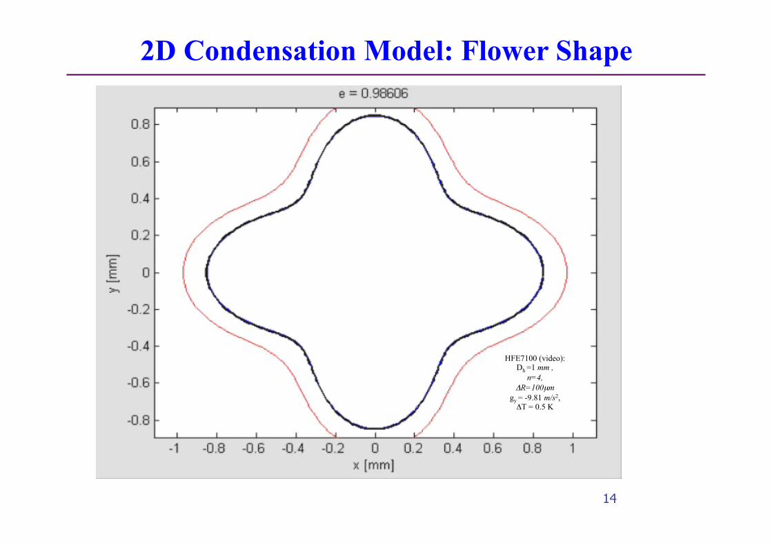
14
Local heat transfer coefficient distribution (red line)
HFE7100 (video): Dh =1 mm ,
n=4, ΔR=100µm
gy = -9.81 m/s2, ΔT = 0.5 K
2D Condensation Model: Flower Shape

15
Steady state condition Mass flow rate: Inlet vapor quality:
250smkgG =
99.0=inX
Fluid: FC-7100 Saturation temperature: Tsat=70°C Wall temperature: Twall=69.5°C Gravity field: |g|=9.81 m/s2
3D Condensation Model: Flower Shape

16
3D Condensation Model: Flower Shape
!

17
inlet section
outlet section
Cross sectional plots of liquid vapor interface at different axial locations
3D Condensation Model: Flower Shape

18
Shape Effects on HTC’s and Pressure Drops

19
• 3D model: recent improvements include transient effects of gravity, uniform heat flux & convective b.c.’s; 1D annular model: includes entrainment, film thickness, etc.
• Our models compare very well vs. experimental data. • Energy efficient condenser designs can be attained using
better pressure drop models…they give the local Tsat for incremental LMTD calculations, so just as important as Uo!
• SHAPE COUNTS! Non-circular channels can improve heat transfer without increase in pressure drop…but non-condensable gas (air) effects need to be investigated.
• Designs should now be looking at true-local h.t.c.’s…those around internal perimeter with air-cooled fins on outside.
• Numerical 2-phase heat transfer DOES have value once it is validated experimentally! Do NOT use non-validated codes.
Recent & Future Steps for Advanced Condensers