numerical studies on constrained venting system with reactive mufflers by ga optimization
TRANSCRIPT

INTERNATIONAL JOURNAL FOR NUMERICAL METHODS IN ENGINEERINGInt. J. Numer. Meth. Engng 2006; 65:1165–1185Published online 11 October 2005 in Wiley InterScience (www.interscience.wiley.com). DOI: 10.1002/nme.1476
Numerical studies on constrained venting system withreactive mufflers by GA optimization
Long-Jyi Yeh∗,†, Ying-Chun Chang‡ and Min-Chie Chiu§
Department of Mechanical Engineering, Tatung University, Taipei 104, Taiwan, R.O.C.
SUMMARY
While the space volume of mufflers in a venting system gets constrained, shape optimization tomaximize the muffler’s performance becomes important and essential. This paper presents a geneticalgorithm (GA) for the optimal shape design of mufflers.
The four-pole matrix method which was adopted in evaluating the acoustic performance of soundtransmission loss (STL) is used in conjunction with the GA techniques. Case studies of the full bandnoise inside a venting system are exemplified by the reactive mufflers. Before the GA operation,several examples are tested and compared with the experimental data for accuracy check of themathematical models. Consequently, GA can provide a quick and effective way for a muffler designwork. Copyright � 2005 John Wiley & Sons, Ltd.
KEY WORDS: reactive muffler; venting system; space constraints; four-pole matrix; GA optimization
1. INTRODUCTION
As a result of the investigation made by the Occupational Safety and Health Act (OSHA)in 1970 [1], it was found out that high noise levels can be psychologically and physiologi-cally harmful to workers. Hence, attention is now focused on the noise control of equipment.Moreover, a lower noise design in a product has become an essential factor for sales andprofits [2].
In dealing with industrial noise from a venting system, a muffler is habitually used [3].However, the shape of the muffler is often constrained depending on the operational andmaintenance needs in practical design works. Besides, the discussion on the optimal designunder space constraints is rarely emphasized. Bernhard [4] has introduced the shape optimization
∗Correspondence to: Long-Jyi Yeh, Department of Mechanical Engineering, Tatung University, 40 Chungshan N. Rd.,3rd Sec., Taipei 104, Taiwan, R.O.C.
†E-mail: [email protected]‡E-mail: [email protected]§E-mail: [email protected]
Received 10 May 2005Copyright � 2005 John Wiley & Sons, Ltd. Accepted 22 July 2005

1166 L.-J. YEH, Y.-C. CHANG AND M.-C. CHIU
of simple expansion mufflers by using design sensitivity matrices. The space volume of thereactive silencer is still non-constrained, but the calculation of the design sensitivity matricesis complicated.
To efficiently perform the shape optimization of simple expansion mufflers, genetic algorithm,a robust and stochastic search method that was modelled after the concept of natural selectionand evolution, is applied. Unlike the traditional gradient methods which need derivatives and agood starting point in an objective function, GA optimizers are able to easily locate the globaloptimum in a near optimal manner. In this paper, GA is coupled with the transfer matrixmethod to optimize the value of the sound transmission loss (STL) by adjusting the shape ofthe reactive mufflers with their space volume under constraints.
2. SYSTEM MODELS
In this paper, four kinds of reactive mufflers were adopted for the noise elimination on the con-strained venting system shown in Figure 1. For the ease of theoretical derivations on four kindsof mufflers, the muffler elements, including (1) straight duct (2) simple expansion/contractionduct; and (3) extended duct, were first of all identified. On the basis of plane wave theorem, atransfer matrix between inlet and outlet were deduced in each muffler unit. By the combinationof transfer matrix for all muffler components, the complete four-pole matrix of the muffler sys-tem was built. Furthermore, the STL was easily calculated by means of the four-pole matrix.The system model in each muffler element is illustrated as follows:
2.1. Single-chamber muffler [5]As depicted in Figure 2, the whole flow condition within the muffler is presented by six nodes(pt1–pt6). On the basis of plane wave theorem, a transfer matrix of each muffler elementbetween inlet and outlet can then be deduced as
(p1
�ocou1
)= e−jM1kL1/(1−M2
1 )
[b11 b12
b21 b22
](p2
�ocou2
)(1)
(p2
�ocou2
)=⎡⎢⎣
1 0
0S3
S2
⎤⎥⎦(
p3
�ocou3
)(2)
(p3
�ocou3
)= e−jM3kL2/(1−M2
3 )
[c11 c12
c21 c22
](p4
�ocou4
)(3)
(p4
�ocou4
)=⎡⎢⎣
1 0
0S5
S4
⎤⎥⎦(
p5
�ocou5
)(4)
Copyright � 2005 John Wiley & Sons, Ltd. Int. J. Numer. Meth. Engng 2006; 65:1165–1185

NUMERICAL STUDIES ON CONSTRAINED VENTING SYSTEM 1167
Figure 1. A constrained venting system with a reactive muffler.
Figure 2. Flow condition for a single-chamber muffler.
(p5
�ocou5
)= e−jM5kL3/(1−M2
5 )
[d11 d12
d21 d22
](p6
�ocou6
)(5)
Using the matrix substitution on Equations (1)–(5), the complete four-pole matrix of the wholemuffler can be built as
(p1
�ocou1
)= e
−jk
(M1L11−M2
1+ M3L2
1−M23
+ M5L3
1−M25
) [b11 b12
b21 b22
]⎡⎢⎣1 0
0S3
S2
⎤⎥⎦[
c11 c12
c21 c22
]
×⎡⎢⎣
1 0
0S5
S4
⎤⎥⎦[
d11 d12
d21 d22
](p6
�ocou6
)
=[
T 11 T 12
T 21 T 22
](p6
�ocou6
)(6)
Copyright � 2005 John Wiley & Sons, Ltd. Int. J. Numer. Meth. Engng 2006; 65:1165–1185

1168 L.-J. YEH, Y.-C. CHANG AND M.-C. CHIU
By using the system matrix in Equation (6), the STL [6] of muffler is deduced as
STL(f, Q, L2, D1, D2) = 20 log
( |T 11 + T 12 + T 21 + T 22|2
)+ 10 log
(S1
S6
)(7)
2.2. Double-chamber muffler [5]The muffler system, comprising of nine elements, is represented by ten points and exposed inFigure 3. The individual transfer matrix in each element is simply expressed as
(p1
�ocou1
)= e−jM1kL1/(1−M2
1 )
[b11 b12
b21 b22
](p2
�ocou2
)(8)
(p2
�ocou2
)=⎡⎢⎣
1 0
0S3
S2
⎤⎥⎦(
p3
�ocou3
)(9)
(p3
�ocou3
)= e−jM3kL2/(1−M2
3 )
[c11 c12
c21 c22
](p4
�ocou4
)(10)
(p4
�ocou4
)=⎡⎢⎣
1 0
0S5
S4
⎤⎥⎦(
p5
�ocou5
)(11)
(p5
�ocou5
)= e−jM5kL3/(1−M2
5 )
[d11 d12
d21 d22
](p6
�ocou6
)(12)
(p6
�ocou6
)=⎡⎢⎣
1 0
0S7
S6
⎤⎥⎦(
p7
�ocou7
)(13)
(p7
�ocou7
)= e−jM7kL4/(1−M2
7 )
[e11 e12
e21 e22
](p8
�ocou8
)(14)
(p8
�ocou8
)=⎡⎢⎣
1 0
0S9
S8
⎤⎥⎦(
p9
�ocou9
)(15)
(p9
�ocou9
)= e−jM9kL5/(1−M2
9 )
[f 11 f 12
f 21 f 22
](p10
�ocou10
)(16)
Copyright � 2005 John Wiley & Sons, Ltd. Int. J. Numer. Meth. Engng 2006; 65:1165–1185

NUMERICAL STUDIES ON CONSTRAINED VENTING SYSTEM 1169
Figure 3. Flow condition for a double-chamber muffler.
By using the matrix substitution on Equations (8)–(16), the complete system matrix is
(p1
�ocou1
)= e
−jk
(M1L11−M2
1+ M3L2
1−M23
+ M5L3
1−M25
+ M7L41−M2
7+ M9L5
1−M29
)
×[
b11 b12
b21 b22
]⎡⎢⎣1 0
0S3
S2
⎤⎥⎦[
c11 c12
c21 c22
]⎡⎢⎣1 0
0S5
S4
⎤⎥⎦[
d11 d12
d21 d22
]
×⎡⎢⎣
1 0
0S7
S6
⎤⎥⎦[
e11 e12
e21 e22
]⎡⎢⎣1 0
0S9
S8
⎤⎥⎦[
f 11 f 12
f 21 f 22
](p10
�ocou10
)
=[
T 11 T 12
T 21 T 22
](p10
�ocou10
)(17)
Consequently, the STL [6] of muffler is obtained as
STL(f, Q, L1, L3, L5, rt1, D1, D2, D3) = 20 log
( |T 11 + T 12 + T 21 + T 22|2
)+ 10 log
(S1
S10
)
(18a)
where
rt1 = L4
L2; L2 = (Lo − L1 − L3 − L5)
(rt1 + 1)(18b)
Copyright � 2005 John Wiley & Sons, Ltd. Int. J. Numer. Meth. Engng 2006; 65:1165–1185

1170 L.-J. YEH, Y.-C. CHANG AND M.-C. CHIU
2.3. Single-chamber muffler with extended tubes [6]Eight nodes within the muffler chosen to observe the flowing condition are revealed in Figure 4.
The individual transfer matrix with respect to each component is illustrated as(p1
�ocou1
)= e−jM1kL12/(1−M2
1 )
[b11 b12
b21 b22
](p2
�ocou2
)(19)
(p2
�ocou2
)=[
TR21,1 TR21,2
TR22,1 TR22,2
](p4
�ocou4
)(20)
(p4
�ocou4
)= e−jM5kL3/(1−M2
5 )
[c11 c12
c21 c22
](p5
�ocou5
)(21)
(p5
�ocou5
)=[
TR41,1 TR41,2
TR42,1 TR42,2
](p7
�ocou7
)(22)
(p7
�ocou7
)= e−jM7kL45/(1−M2
7 )
[d11 d12
d21 d22
](p8
�ocou8
)(23)
Using the matrix substitution on Equations (19)–(23), the four-pole system matrix areexpressed as (
p1
�ocou1
)= e
−jk
(M1L121−M2
1+ M5L3
1−M25
+M7L451−M2
7
)
×[
b11 b12
b21 b22
][TR21,1 TR21,2
TR22,1 TR22,2
][c11 c12
c21 c22
]
×[
TR41,1 TR41,2
TR42,1 TR42,2
][d11 d12
d21 d22
](p8
�ocou8
)
=[
T 11 T 12
T 21 T 22
](p8
�ocou8
)(24)
Figure 4. Flow condition for a single-chamber muffler with extended tubes.
Copyright � 2005 John Wiley & Sons, Ltd. Int. J. Numer. Meth. Engng 2006; 65:1165–1185

NUMERICAL STUDIES ON CONSTRAINED VENTING SYSTEM 1171
The STL [6] of a muffler is obtained as
STL(f, Q, D1, D2, L1, L5, rt1, rt2) = 20 log
( |T 11 + T 12 + T 21 + T 22
2
)+ 10 log
(S1
S8
)(25a)
where
rt1 = L2
L3; rt2 = L4
L3; L3 = (Lo − L1 − L5)
(rt1 + rt2 + 1)(25b)
2.4. Double-chamber muffler with extended tubes [6]As shown in Figure 5, fourteen nodes representing the flowing situation within the mufflerare built. The sub-matrices with respect to nine component of the muffler are expressed asfollows:
(p1
�ocou1
)= e−jM1kL12/(1−M2
1 )
[b11 b12
b21 b22
](p2
�ocou2
)(26)
(p2
�ocou2
)=[
TR21,1 TR21,2
TR22,1 TR22,2
](p4
�ocou4
)(27)
(p4
�ocou4
)= e−jM5kL3/(1−M2
5 )
[c11 c12
c21 c22
](p5
�ocou5
)(28)
(p5
�ocou5
)=[
TR41,1 TR41,2
TR42,1 TR42,2
](p7
�ocou7
)(29)
(p7
�ocou7
)= e−jM7kL456/(1−M2
7 )
[d11 d12
d21 d22
](p8
�ocou8
)(30)
Figure 5. Flow condition for a double-chamber muffler with extended tubes.
Copyright � 2005 John Wiley & Sons, Ltd. Int. J. Numer. Meth. Engng 2006; 65:1165–1185

1172 L.-J. YEH, Y.-C. CHANG AND M.-C. CHIU
(p8
�ocou8
)=[
TR61,1 TR61,2
TR62,1 TR62,2
](p10
�ocou10
)(31)
(p10
�ocou10
)= e−jM10kL7/(1−M2
10)
[e11 e12
e21 e22
](p11
�ocou11
)(32)
(p11
�ocou11
)=[
TR81,1 TR81,2
TR82,1 TR82,2
](p13
�ocou13
)(33)
(p13
�ocou13
)= e−jM13kL89/(1−M2
13)
[f 11 f 12
f 21 f 22
](p14
�ocou14
)(34)
By using the matrix substitution on Equations (26)–(34), the system matrix of the muffleryields (
p1
�ocou1
)= e
−jk
(M1L121−M2
1+ M5L3
1−M25
+M7L4561−M2
7+ M10L7
1−M210
+M13L89
1−M213
)
×[
b11 b12
b21 b22
][TR21,1 TR21,2
TR22,1 TR22,2
][c11 c12
c21 c22
][TR41,1 TR41,2
TR42,1 TR42,2
]
×[
d11 d12
d21 d22
][TR61,1 TR61,2
TR62,1 TR62,2
][e11 e12
e21 e22
][TR81,1 TR81,2
TR82,1 TR82,2
]
×[
f 11 f 12
f 21 f 22
](p14
�ocou14
)=[
T 11 T 12
T 21 T 22
](p14
�ocou14
)(35)
The STL [6] of a muffler is calculated as
STL(f, Q, D2, L1, L3, L5, L9, rt1, rt2, rt3, rt4)
= 20 log
( |T 11 + T 12 + T 21 + T 22|2
)+ 10 log
(S1
S14
)(36a)
where
rt1 = L2
L3; rt2 = L4
L3; rt3 = L6
L7; rt4 = L8
L7
L7 = Lo − L1 − L5 − L9 − (rt1 + rt2 + 1)
1 + rt3 + rt4
(36b)
Copyright � 2005 John Wiley & Sons, Ltd. Int. J. Numer. Meth. Engng 2006; 65:1165–1185

NUMERICAL STUDIES ON CONSTRAINED VENTING SYSTEM 1173
2.5. Overall sound pressure level
Therefore, the silenced octave sound level at receiver is
SPLi = SPLOi − STLi (37)
where
(1) SPLOi is the original SPL at inlet of muffler (or pipe outlet), and i is the index of octaveband frequency.
(2) STLi is the muffler’s STL with respect to the relative octave band frequency.(3) SPLi is the silenced SPL at outlet of muffler with respect to the relative octave band
frequency.
Finally, the overall SPLT silenced by muffler at outlet is
SPLT = 10 ∗ log
{8∑
i=110SPLi /10
}
= 10 ∗ log
⎧⎪⎪⎪⎪⎨⎪⎪⎪⎪⎩
10[SPLO(f =63)−STL(f =63)]/10 + 10
[SPLO(f =125)−STL(f =125)] + 10
[SPLO(f =250)−STL(f =250)]/10
+10[SPLO(f =500)−STL(f =500)]/10 + 10
[SPLO(f =1000)−STL(f =1000)]/10 + 10
[SPLO(f =2000)−STL(f =2000)]/10
+10[SPLO(f =4000)−STL(f =4000)]/10 + 10
[SPLO(f =8000)−STL(f =8000)]/10
⎫⎪⎪⎪⎪⎬⎪⎪⎪⎪⎭
(38)
2.6. Objective function
By using the formula of Equation (38), the objective function used in GA optimization withrespect to each type of reactive muffler was established.
For the type of single-chamber, the objective function is
OBJ = SPL(Q, L2, D1, D2) (39)
For the type of double-chamber, the objective function is
OBJ = SPL(Q, L1, L3, L5, rt1, D1, D2, D3) (40a)
where
rt1 = L4
L2; L2 = (Lo − L1 − L3 − L5)
(rt1 + 1)(40b)
For the type of single-chamber with extended tubes, the objective function is
OBJ = SPL(Q, D1, D2, L1, L5, rt1, rt2) (41a)
where
rt1 = L2
L3; rt2 = L4
L3; L3 = (Lo − L1 − L5)
(rt1 + rt2 + 1)(41b)
Copyright � 2005 John Wiley & Sons, Ltd. Int. J. Numer. Meth. Engng 2006; 65:1165–1185

1174 L.-J. YEH, Y.-C. CHANG AND M.-C. CHIU
For the type of double-chamber with extended tubes, the objective function is
OBJ = SPL(Q, D2, L1, L3, L5, L9, rt1, rt2, rt3, rt4) (42a)
where
rt1 = L2
L3; rt2 = L4
L3; rt3 = L6
L7; rt4 = L8
L7
L7 = Lo − L1 − L5 − L9 − (rt1 + rt2 + 1)
1 + rt3 + rt4
(42b)
3. MODEL CHECKS
Before performing the GA optimal simulation on mufflers, the accuracy checks of mathematicalmodels on two kinds of fundamental mufflers, including the single-muffler and the single-mufflerhybridized with extended tubes, are made by experiment data [7]. As depicted in Figures 6and 7, the accuracy comparisons between theoretical and experiment data for the models arein good agreements. Therefore, the proposed fundamental mathematical models are acceptable.
Figure 6. Performance of single-chamber muffler at the mean flow velocity of 3.4 m/s [D1 = D2 =0.0365 (m); D0 = 0.108 (m); L1 = L3 = 0.1 (m); L2 = 0.208 (m)].
Copyright � 2005 John Wiley & Sons, Ltd. Int. J. Numer. Meth. Engng 2006; 65:1165–1185

NUMERICAL STUDIES ON CONSTRAINED VENTING SYSTEM 1175
Figure 7. Performance of single-chamber muffler with extended tubes at themean flow velocity of 3.4 m/s [D1 = D2 = 0.0365 (m); D0 = 0.108 (m); L1 = L5= 0.1 (m); L2 = L4 = 0.052 (m); L3 = 0.104 (m)].
Consequently, the models linked with numerical method are applied for the shape optimizationin the following section.
4. CASE STUDIES
In this paper, a venting system confined within a reinforced concrete (RC) room is introducedand shown in Figure 1. Four kinds of mufflers, including (1) single-chamber muffler; (2)double-chamber muffler; (3) single-chamber muffler with extended tubes; and (4) doubled-chamber muffler with extended tubes, are chosen and simulated. The spectrum of equipment’ssound pressure level (SPL) at muffler inlet is
f (Hz) 63 125 250 500 1k 2k 4k 8k
SPL-dB(A) 86 90 94 93 104 95 91 88
The available space for a muffler is 0.3 m in length, 0.3 m in width and 1.0 m in height. Anattempt for optimal reduction design of a muffler at the muffler outlet is made under theboundary constraint. The corresponding space constraints and the ranges of design parametersfor each muffler are summarized in Table I. In addition, to avoid the larger pressure drop and
Copyright � 2005 John Wiley & Sons, Ltd. Int. J. Numer. Meth. Engng 2006; 65:1165–1185

1176 L.-J. YEH, Y.-C. CHANG AND M.-C. CHIU
Table I. Range of design parameters for four kinds of muffler.
Muffler-type Range of design parameters
Single-chamber D1 : [0.0762, 0.3]; D2 : [0.0762, 0.3]; L2 : [0.1, 0.8]Double-chamber D1 : [0.0762, 0.3]; D2 : [0.0762, 0.3]; D3 : [0.0762, 0.3]; L1 : [0.1, 0.2];
L3 : [0.1, 0.2]; L5 : [0.1, 0.2]; rt1 : [0.5, 2.0]Single-chamber with D1 : [0.0762, 0.3]; D2 : [0.0762, 0.3]; L1 : [0.1, 0.3]; L5 : [0.1, 0.3];extended tube rt1 : [0.2, 2]; rt2 : [0.2, 2]Double-chamber with D2 : [0.0762, 0.3]; L1 : [0.05, 0.15]; L3 : [0.1, 0.3]; L5 : [0.05, 0.15];extended tube L9 : [0.05, 0.15]; rt1 : [0.1, 1]; rt2 : [0.1, 1]; rt3 : [0.1, 1]; rt4 : [0.1, 1]
flow’s generated noise occurred in muffler [8], the necessities of minimal diameters at bothends were specified to no less than 0.0762(m), which was the OD of venting device. Moreover,the given volume flow rate, Q, at venting outlet was confined to 0.8 (m3/s).
5. GENETIC ALGORITHM
The concept of Genetic Algorithms, first formalized by Holland [9] and extended to functionaloptimization by Jong [10] later involves the use of optimization search strategies patternedafter Darwinian notion of natural selection and evolution. During a GA optimization, one setof trial solutions was chosen and ‘evolved’ toward an optimal solution. The basic operationof a GA consisted of the following steps: (1) initialize randomly a population of individuals;(2) evaluate the individuals following their fitness value; (3) apply genetic operators (crossover,mutation and elitism) to the population; (4) repeat step (2)–(3) until the best individual isreached. Here, the techniques of binary genetic algorithms (BGA) were also applied. In thefollowing, we give a short description of the genetic algorithm as below:
A. Populations and chromosomes: For the optimization (minimum) of the objective function(OBJ) with the design parameters of (x1, x2, . . . , xk). As the bit length of bit_n, which interms of the chromosome, was chosen first, the interval of the kth design parameter (xk) with[Lb, Ub]k was thereafter mapped to the band of binary value. The mapping system between thevariable interval of [Lb, Ub]k and the kth binary chromosome of [000000 . . . 0000 ∼ 111111 . . .
1111]k was then built. The encoding from x to B2D can be performed as
B2Dk = integer
{xk − Lbk
Ubk − Lbk
(2bit_n − 1)
}
The initial population was built up by randomization. The parameter set was encoded toform a string which represented the chromosome. The more there was an increase in bit length,the better resolution of optimization.
By evaluation of the objective function (OBJ), the whole set chromosome of [B2D1, B2D2,
. . . , B2Dk] that changed from binary form to decimal form was then assigned a fitness bydecoding the transformation system individuallyfitness = OBJ(X1, X2, . . . , Xk);where Xk = B2Dk ∗ (Ubk − Lbk)/(2bit_n − 1) + Lbk .
Copyright � 2005 John Wiley & Sons, Ltd. Int. J. Numer. Meth. Engng 2006; 65:1165–1185

NUMERICAL STUDIES ON CONSTRAINED VENTING SYSTEM 1177
Figure 8. Operations in GA method.
B. Parents: By using the probabilistic computation weighted by the relative fitness, pairsof chromosome were selected as parents. The weighted roulette wheel selection was thenapplied. Each individual in the population was assigned space on the roulette wheel which wasproportional to the individual relative fitness.
For the n set of parent in the mating pool, the weighted roulette wheel for the kkth individualwas represented as fitnesskk∑n
i=1 fitnessi∗ 100%.
Individuals with the largest portion on the wheel have the greatest probability to be selectedas parent generation for the next generation.
C. Crossover: One pair of offspring was generated from the selected parent by crossover.Crossover occurred with a probability of pc. Both the random selection of a crossover andcombination of the two parent’s genetic data were then preceded. The scheme of single-point crossover was chosen in GA’s optimization. Recombination and parent selection werethe principle methods for the evolution in GA. For the k numbers of design variables in theobjective function (OBJ), the crossover operation with respect to individual chromosome of[B2D1, B2D2, . . . , B2Dk] were carried out in the binary form simultaneously.
D. Mutation: Genetically, mutation occurred with a probability of pm of which the newand unexpected point were brought into the GA optimizer’s search domain. The operation wasperformed by changing the value of the bit from one to zero or zero to one at the selectedpoint. It was an essential operation to increase the diversity of population that was able toescape from the local optimum during GA’s optimization. For the k numbers of design variablesin the objective function (OBJ), the mutation operation with respect to individual chromosomeof [B2D1, B2D2, . . . , B2Dk] were carried out in the binary form simultaneously.
E. Elitism: To prevent the best gene from disappearing and improve the accuracy of opti-mization during reproduction, the elitism scheme of keeping the best gene (one pair) in theparent generations was thus presented and developed.
Copyright � 2005 John Wiley & Sons, Ltd. Int. J. Numer. Meth. Engng 2006; 65:1165–1185

1178 L.-J. YEH, Y.-C. CHANG AND M.-C. CHIU
Start
Program terminate
Yes
No
New population is built?
No
Evaluate Fitness Decoding/
EncodingObjective Function : OBJ
Elitism
gen_no > gen_nomax
Yes
Calculation of Transfer Matrices, STL
Set popuSize, bit_n, pc, pm, elt_no, gen_nomax , Q, Constraints
Single-point crossover
Select candidate parents by roulette wheel scheme
Mutation
Initialize Population (Randomize) in binary code
Figure 9. Block diagram of the GA optimization on mufflers.
F. New Generation: Reproduction included selection, crossover, mutation and elitism. TheReduplication continued until a new generation was constructed and the original generationwas substituted. Highly fit characteristics produced more copies of themselves in subsequentgeneration resulting in a movement of the population towards an optimal direction. The processwas terminated when number of generations, gen_nomax, exceeded a pre-selected value.
The operations in GA method are pictured in Figure 8. In addition, the block diagram ofGA optimization on mufflers is depicted in Figure 9.
6. RESULTS AND DISCUSSION
6.1. Results
The size of the population (popuSize) is set at 60, while the maximum generation (gen_no)is set at 500, and the bit length at 40 (bit_n). According to Johnson and Yahya [11], thetypical crossover ratio (pc) and the mutation ratio (pm) used in the following GA optimizationsare at 0.8 and 0.05, respectively. To achieve a better approach in GA, four trial cases withdifferent values of the control parameters (pc, pm and elt_no) were tested and analysed. The
Copyright � 2005 John Wiley & Sons, Ltd. Int. J. Numer. Meth. Engng 2006; 65:1165–1185

NUMERICAL STUDIES ON CONSTRAINED VENTING SYSTEM 1179
Table II. Comparison of results for single-chamber muffler.
Common parameters Control parameters Results Elapsedtime
popuSize gen_no bit_no pc pm elt_no D1 (m) L2 (m) D2 (m) SPL t (min)
Case 1 60 500 40 0.8 0.05 1 0.0762 0.4691 0.0762 89.2 1.47Case 2 60 500 40 0.8 0.05 0 0.0785 0.5606 0.0797 89.9 1.46Case 3 60 500 40 0.8 0 1 0.1193 0.4598 0.0762 93.0 1.46Case 4 60 500 40 0 0.05 1 0.0801 0.4764 0.0781 89.9 1.42
Figure 10. Comparison of resultant SPL on a single-chamber muffler by varying GA parameters.
other parameters such as the bit_n, popuSize, and gen_no have fixed values. The optimizationsystem is encoded by MATLAB and made to run in an IBM PC—Pentium IV. The four kindsof multi-segment mufflers are described as follows:
A. Single-chamber muffler: Four sets of GA parameters are tested. The simulated results aresummarized and shown in Table II. As indicated in Table II, the optimal design data can beobtained from the first set of GA parameters. All of the resultant curves of the SPL withrespect to frequency are plotted for comparison in Figure 10. It reveals that the first designdata can still improve the level of noise reduction over the whole band of spectrum.
B. Double-chamber muffler: Four sets of GA parameters are tested. The simulated resultsare summarized and shown in Table III. As indicated in Table III, the optimal design data
Copyright � 2005 John Wiley & Sons, Ltd. Int. J. Numer. Meth. Engng 2006; 65:1165–1185

1180 L.-J. YEH, Y.-C. CHANG AND M.-C. CHIU
Tabl
eII
I.C
ompa
riso
nof
resu
ltsfo
rdo
uble
-cha
mbe
rm
uffle
r.
Com
mon
para
met
ers
Con
trol
para
met
ers
Res
ults
Ela
psed
time
popu
Size
gen_
nobi
t_no
pcpm
elt_
noD
1(m
)D
2(m
)D
2(m
)L
1(m
)L
3(m
)L
5(m
)rt
1SP
Lt(m
in)
Cas
e1
6050
040
0.8
0.05
10.
0762
0.29
980.
0762
0.10
010.
1717
0.10
001.
2283
93.6
3.30
Cas
e2
6050
040
0.8
0.05
00.
0792
0.28
110.
0771
0.10
110.
1349
0.13
150.
7588
95.0
3.41
Cas
e3
6050
040
0.8
01
0.07
620.
2930
0.07
630.
1467
0.12
690.
1019
0.78
3294
.53.
40C
ase
460
500
400
0.05
10.
0836
0.25
970.
0767
0.15
400.
1848
0.10
061.
5509
95.5
3.25
Tabl
eIV
.C
ompa
riso
nof
resu
ltsfo
rsi
ngle
-cha
mbe
rm
uffle
rw
ithex
tend
edtu
bes.
Com
mon
para
met
ers
Con
trol
para
met
ers
Res
ults
Ela
psed
time
popu
Size
gen_
nobi
t_no
pcpm
elt_
noD
1(m
)D
2(m
)L
1(m
)L
5(m
)rt
1rt
2SP
Lt(m
in)
Cas
e1
6050
040
0.8
0.05
10.
0763
0.07
620.
1002
0.10
011.
9986
0.47
6282
.47.
62C
ase
260
500
400.
80.
050
0.07
900.
0821
0.19
390.
2205
0.52
830.
2096
86.9
7.62
Cas
e3
6050
040
0.8
01
0.08
240.
0848
0.28
160.
1370
1.37
620.
8194
91.0
7.61
Cas
e4
6050
040
00.
051
0.07
870.
0852
0.13
690.
1505
1.98
550.
4105
87.5
7.46
Tabl
eV
.C
ompa
riso
nof
resu
ltsfo
rdo
uble
-cha
mbe
rm
uffle
rw
ithex
tend
edtu
bes.
GA
para
met
ers
Res
ults
Ela
psed
time
pcpm
elt_
noD
2(m
)L
1(m
)L
3(m
)L
5(m
)L
9(m
)rt
1rt
2rt
3rt
4SP
Lt(m
in)
Cas
e1
0.8
0.05
10.
2998
0.05
050.
2007
0.12
310.
0503
0.65
870.
1019
0.99
310.
3494
77.9
11.7
5C
ase
20.
80.
050
0.29
960.
0637
0.21
120.
0986
0.05
710.
9032
0.10
120.
9701
0.66
1778
.811
.70
Cas
e3
0.8
01
0.28
510.
1084
0.20
050.
1021
0.07
900.
9006
0.11
430.
5301
0.25
1480
.411
.68
Cas
e4
00.
051
0.08
050.
0788
0.15
680.
0664
0.06
650.
1699
0.13
950.
2067
0.10
3278
.011
.53
Copyright � 2005 John Wiley & Sons, Ltd. Int. J. Numer. Meth. Engng 2006; 65:1165–1185
NUMERICAL STUDIES ON CONSTRAINED VENTING SYSTEM 1181
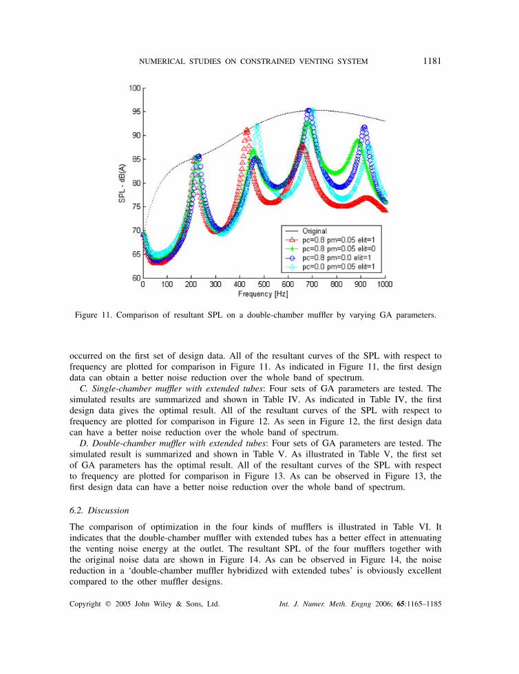
Figure 11. Comparison of resultant SPL on a double-chamber muffler by varying GA parameters.
occurred on the first set of design data. All of the resultant curves of the SPL with respect tofrequency are plotted for comparison in Figure 11. As indicated in Figure 11, the first designdata can obtain a better noise reduction over the whole band of spectrum.
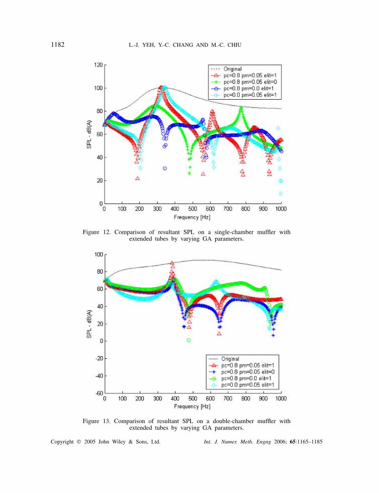
C. Single-chamber muffler with extended tubes: Four sets of GA parameters are tested. Thesimulated results are summarized and shown in Table IV. As indicated in Table IV, the firstdesign data gives the optimal result. All of the resultant curves of the SPL with respect tofrequency are plotted for comparison in Figure 12. As seen in Figure 12, the first design datacan have a better noise reduction over the whole band of spectrum.
D. Double-chamber muffler with extended tubes: Four sets of GA parameters are tested. Thesimulated result is summarized and shown in Table V. As illustrated in Table V, the first setof GA parameters has the optimal result. All of the resultant curves of the SPL with respectto frequency are plotted for comparison in Figure 13. As can be observed in Figure 13, thefirst design data can have a better noise reduction over the whole band of spectrum.
6.2. Discussion
The comparison of optimization in the four kinds of mufflers is illustrated in Table VI. Itindicates that the double-chamber muffler with extended tubes has a better effect in attenuatingthe venting noise energy at the outlet. The resultant SPL of the four mufflers together withthe original noise data are shown in Figure 14. As can be observed in Figure 14, the noisereduction in a ‘double-chamber muffler hybridized with extended tubes’ is obviously excellentcompared to the other muffler designs.
Copyright � 2005 John Wiley & Sons, Ltd. Int. J. Numer. Meth. Engng 2006; 65:1165–1185
1182 L.-J. YEH, Y.-C. CHANG AND M.-C. CHIU
Figure 12. Comparison of resultant SPL on a single-chamber muffler withextended tubes by varying GA parameters.
Figure 13. Comparison of resultant SPL on a double-chamber muffler withextended tubes by varying GA parameters.
Copyright � 2005 John Wiley & Sons, Ltd. Int. J. Numer. Meth. Engng 2006; 65:1165–1185

NUMERICAL STUDIES ON CONSTRAINED VENTING SYSTEM 1183
Table VI. Comparison of results in four kinds of mufflers.
ResultantSPL (dB)
Single-chamber muffler 89.2Double-chamber muffler 93.6Single-chamber with extended tube 82.4Double-chamber with extended tube 77.9
Figure 14. Comparison of optimal resultant SPL in four kinds of mufflers.
Moreover, according to Tables II–V, the simulation times with respect to these mufflers arein the range of 1–12 min. The more complex is the mechanism in the muffler, the more timeit takes to undergo optimal simulation.
7. CONCLUSION
It has been shown that GA can be used in the optimization of the noise control in the ventingsystem by adjusting the shape of the muffler under space constraints. GA is easier to usecompared to the traditional gradient method that requires a good starting point. As seen in theanalysis of Section 6, GA operators of crossover, mutation and elitism are all essential in GAoptimization. The lack of any one of the GA operators will result in either inaccuracy of thesolution or postponement in the convergence. Furthermore, the case studies involving the four
Copyright � 2005 John Wiley & Sons, Ltd. Int. J. Numer. Meth. Engng 2006; 65:1165–1185

1184 L.-J. YEH, Y.-C. CHANG AND M.-C. CHIU
kinds of mufflers reveal that the muffler hybridized with double chambers and extended tubeshas a better capacity for noise elimination.
Consequently, the approach of using GA optimization in the mufflers’ shape design providesa quick and effective method without the complicated calculations of the traditional gradientapproach or the performance of redundant laboratory testing works.
NOMENCLATURE
This paper is constructed on the basis of the following notations:
bit_n bit lengthCo sound speed (m s−1)
Di diameter at ith element (m)elt_no selection of elite (1 for yes and 0 for no)f frequency (Hz)gen_no maximum no. of generationj
√−1k wave numberLi length (m) at ith element (m)Mi mean flow Mach number at ith nodeOBJ objective functionpc crossover ratiopi pressure; acoustic pressure at ith node (Pa)pm mutation ratiopopuSize no. of populationQ volume flow rate (m3 s−1)
Si section area at ith node (m2)
SPL sound pressure level (dB(A))STL sound transmission loss (dB)ui acoustic particle velocity at ith node (m s−1)
�o air density (kg m−3)
REFERENCES
1. Cheremisinoff PN, Cheremisinoff PP. Industrial Noise Control Handbook. Ann Arbor Science: Michigan,1977.
2. Kaiser L, Bernhardt H. Noise control on computer and business equipment using speed control blowers.IEEE 1989; 2:114–117.
3. Magrab EB. Environmental Noise Control. Wiley: New York, 1975.4. Bernhard RJ. Shape optimization of reactive mufflers. Noise Control Engineering Journal 1986; 27(1):10–17.5. Yeh LJ, Chiu MC, Lai GJ. Computer aided design on single expansion muffler under space constraints.
Proceedings of the 19th National Conference on Mechanical Engineering, vol. C7. The Chinese Society ofMechanical Engineers: Hu-Wei county; Taiwan, 2002; 625–633.
6. Munjal ML. Acoustics of Ducts and Mufflers with Application to Exhaust and Ventilation System Design.Wiley: New York, 1987.
7. Wang CN, Hsieh CC. Experimental study for muffler components with flow. Bulletin of the College ofEngineering, N.T.U., 78, 2000; 67–74.
Copyright � 2005 John Wiley & Sons, Ltd. Int. J. Numer. Meth. Engng 2006; 65:1165–1185

NUMERICAL STUDIES ON CONSTRAINED VENTING SYSTEM 1185
8. Bies DA, Hansen CH. Engineering Noise Control. Unwin Hyman: UK, 1988.9. Holland JH. Adaptation in Natural and Artificial System. The University of Michigan Press: Ann Arbor, MI,
1975.10. Jong D. Analysis of the behavior of a class of a genetic adaptive systems. Ph.D. Dissertation, The University
of Michigan Press, 1975.11. Johnson JM, Yahya RS. Genetic algorithm optimization and its application to antenna design. Proceedings
of the IEEE Antennas and Propagation Society International Symposium, 1994; 326–331.
Copyright � 2005 John Wiley & Sons, Ltd. Int. J. Numer. Meth. Engng 2006; 65:1165–1185