numerical study of hydrodynamics and thermal
TRANSCRIPT

NUMERICAL STUDY OF HYDRODYNAMICS
AND THERMAL CHARACTERISTICS OF HEAT EXCHANGERS
WITH DELTA WINGLETS
by
Yu WANG
*
School of Aeronautics, Northwest Polytechnical University, Xi’an, Shaanxi, China
Original scientific paper https://doi.org/10.2298/TSCI180330254W
The comprehensive performance of heat exchangers is represented by the maxi-mum thermal transfer, the minimum pressure loss, and the smallest pumping power. In recent years, the application of longitudinal vortex generators is devel-oped as an effective technique and important research topic, which could increase the heat transfer enhancement of compact heat exchangers. A 3-D CFD numerical simulation is successfully carried out on thermohydraulic characteristics of the fin-and-tube compact heat exchanger with new types of vortex generators. The effects of six different arrangement of delta winglets are studied, which are front-up-rear-down, front-down-rear-up, common-flow-up, and common-flow-down. In addition, there are also different direction of hole position in the same delta winglets ar-rangement. The investigation of thermal-hydraulic performance is conducted for Reynolds number in the range of 204-2034. The overall and local performance comparisons among the fin with delta winglets and the wavy fin are performed. Then, the comprehensive performance evaluation diagram was adopted to analyze the combined index point of thermal and flow. This study shows that the flow dis-tinction between different fins has a profound influence on the thermal-hydrody-namic performance. The results reveal that the fin with delta winglets can consid-erably strengthen the thermal efficiency with a moderate pressure loss penalty. The computational results indicate that the average j-factor for the fin with delta wing-lets can be increased up to 41.9% over the baseline case and the corresponding f-factor decreased up to 19.5%. The combination property of front-up-rear-down are better the others at lower Reynolds number, and that of front-down-rear-up are better at higher Reynolds number. Compare with the traditional arrangement (common-flow-up and common-flow-down), The newly designed fin has great ef-fectiveness and uniform performance in the local region.
Key words: numerical simulation, delta winglet, hydrodynamics, heat transfer, longitudinal vortices
Introduction
Fin-and-tube heat exchangers are widely used in many fields such as energy and power engineering, petroleum and chemical engineering, and metallurgy and material engineer-ing, especially in HVACR systems. The dominant thermal resistance of fin-and-tube heat ex-changer is usually on the air side due to the low thermal conductivity of the air. Therefore, the utilization of the fin pattern in the air-side to enhance the heat transfer is an important measure to reduce the thermal resistance and increase the energy efficiency of the fin-and-tube heat exchanger. The first generation of the fin pattern of the fin-and-tube heat exchanger is the plain –––––––––––––– * Authors’, e-mail: [email protected]
fin [1], which increases the heat exchanger surface area and improves the heat transfer coeffi-cient. The second generation of the fin pattern is the continuous wavy fin, which periodically changes the main-flow direction and cause better flow mixing. The third generation of the fin pattern is of discontinuous type such as slit and louvered fin geometries. They could periodi-cally interrupt the thermal boundary-layer, break and renew the laminar sub-layer, change the direction of main-flow. The interrupted surface can significantly improve the heat transfer co-efficient by producing horizontal vortices. However, the associated penalty of the pressure drop is also large, which lead to a high operating cost and noises. In the recent years, the fourth generation of the fin pattern with longitudinal vortex generators (LVG) is proposed and re-ceived more and more attentions. As a special extended surface, LVG are usually incorporated into a heat transfer surface with an attack angle by means of embossing, stamping, or punching process [2]. When the fluid-flows over the LVG, the flow was separated and longitudinal vor-tices was generated downstream by the pressure difference across the vortex generators. Jacobi and Shah [3] and Fiebig [4] both noted that the longitudinal vortices could enhance the heat transfer performance with relatively low penalty of pressure drops.
The first literature reporting the impact of vortex generators on the heat transfer is given by Jonhnson and Joubert [5]. Biswas [6] numerically investigated the flow structure and heat transfer enhancement in a fin-and-tube heat exchanger channel with a pair of delta wing-lets. The results showed that the enhancement of local heat transfer increased by 240% in the wake region behind the tube by the winglets placed and longitudinal vortices generated. Torii et al. [7] proposed a novel delta winglet configuration named as common-flow-up (CFU). The winglet pair is usually deployed upstream adjacent to the tube, and the transverse distance be-tween the leading edges of the winglet pair is larger than that of the trailing edges. This config-uration was shown to be effective in delaying boundary-layer separation from the tube, reducing form drag of the tube, and diminishing the zone of poor heat transfer from the near-wake behind the tube. Jain et al. [8] numerically simulated the flow structure and heat transfer in a rectangu-lar channel with a built-in circular tube and delta winglets in a CPU configuration. Compared with the baseline case with a Reynolds number at 103, the average Nusselt number of the en-hanced case was increased by 35%. However, the friction factor was not computed. For appli-cations of the fin-and-tube heat exchanger with LVG, O'Brien [9] carried out an experimental study in a narrow duct fitted with a circular tube and a delta winglet pair. The results of overall mean fin surface Nusselt number showed a significant heat transfer enhancement. Near the range of lower Reynolds number, the enhancement was nearly two times. At higher Reynolds number, the enhancement was close to 50%. Pesteei et al. [10] experimentally studied the effect of delta winglet location on the heat transfer enhancement and pressure drop in plain fin-and-tube heat exchangers. The results showed that the average Nusselt number increased by about 46% while the pressure drop increased by only 18%. The delta winglet configuration in the aforementioned literatures was common-flow-down. The winglet pair is placed downstream of the tube in the near-wake region, and the transverse distance between the leading edges of the winglet pair is less than that of the trailing edges. Joardar and Jacobi [11, 12] carried out a numerical and experimental study of the flow and heat transfer in a seven-row plain fin-and-tube heat exchanger with different delta winglet array designs in a CFU configuration. The results indicated that the performance of fin-and-tube heat exchangers were significantly im-proved by vortex generator arrays. The numerical results of the total heat transfer quantities were verified well by the available experimental measurements. He numerically studied the air-side heat transfer and fluid-flow characteristics of the fin-and-tube heat exchanger with delta winglets in a number of different configurations [13-16]. Effects of some important parameters

on the heat transfer and fluid-flow performances were examined, such as the attack angle, the length and height of delta winglet, the tube row number, and the arrangement of delta winglet. Tang et al. [17] experimentally investigated the air-side heat transfer and friction characteristics of five kinds of fin-and-tube heat exchangers, including the crimped spiral fin, the plain fin, the slit fin, the fin with delta winglets, and the mixed fin with front 6-row delta winglets, and rear 6-row slit. The air-side performance of heat exchangers was evaluated under three sets of cri-teria and the slit fin offered the best heat transfer performance at high Reynolds numbers. Wu et al. [18, 19] showed that it is possible to enhance heat transfer with reduction in pressure drop with two rows of tubes in different diameters by using LVG. Analyzed the mechanism of heat transfer enhancement by the field synergy principle in fin-and-tube heat exchanger with LVG in aligned arrangement. Du et al. [20] experimentally studied two kinds of finned tube heat exchangers in an indirect air-cooling tower. The performance of longitudinal vortex and trans-verse vortex was compared and analyzed. In recent years, more and more kind of new finned tube heat exchanger type has been proposed and studied by scholars. Gholami et al. [21] nu-merically investigated the fin-and-tube compact heat exchangers with wavy rectangular wing-let-type vortex generators in a relatively low Reynolds number flow. The results shows that it could significantly improve the heat transfer performance with a moderate pressure loss pen-alty. Lotfi et al. [22] carried out a numerical simulation on thermohydraulic characteristics of a new smooth wavy fin-and-elliptical tube heat exchanger with three new types of vortex gener-ators. Bhuiyan and Islam [23] reviewed, grouped and summarized different experimental/nu-merical studies based on the types of heat exchangers, heat transfer and pressure drop perfor-mance, effects of geometrical parameters under different flow conditions. Deng and Qian [24] tested three versions of fin collar and made some CFD simulations in order to find out the rules of thermal contact resistance varying. Sarangi and Mishra [25] numerically investigated the heat transfer enhancement and pressure loss of a fin-and-tube heat exchanger with different number of rectangular winglet pairs. Gholami et al. [26] numerically studied the one-corrugated and three-corrugated fins with oval tubes, which could promise a large leap in the development of minimized heat exchangers with increased thermal efficiency. Valikangas et al. [27] studied the effect of vortex generators in a fin-and-tube heat exchanger with herringbone fin shape. The combined enhancement with herringbone fin and the vortex generators is evaluated by simulat-ing the conjugate heat transfer and the air-flow.
The foregoing literature reviews show that the delta winglets can effectively create secondary flow, mix the main flow, reduce the flow boundary, and enhance the heat transfer. For the wavy fin, which is widely used in air-conditioning and refrigeration fields, however, there are some wake regions behind the tube and the local heat transfer is very feeble. The application of the delta winglet in the fin can effectively improve these situations. The present study will focus on the heat transfer and fluid flow characteristics of the fin-and-tube heat ex-changer with delta winglets in some new arrangement configuration. The performance compar-isons among the fin with delta winglets and commercial wavy fin will be performed. The en-ergy-saving performance evaluation criteria will be used to quantitatively assess the overall performance of these different fins.
Model description
Physical model
Some kinds of fin-and-tube heat exchangers will be numerically investigated in this study, which have the same tube and fin geometries but different fin surface patterns. The heat

exchangers are all relative to one-row round tube. The tube outside diameter is 7.3 mm and the transverse tube pitch is 21 mm. The fin length along the air main flow direction is 18.19 mm. The different fin surface patterns are wavy fin (Case 0) and the fin with delta winglets (Cases 1-6), which were optimized from many kinds of punched structures. The wavy fin in this paper is the commercial fin patterns applied in the outdoor heat exchanger in air conditioning systems. The schematic diagram and geometric dimension of wavy fin is shown in fig. 1 and tab. 1. The schematic diagram of delta winglets configurations is shown in fig. 2, in which x, y, and z are streamwise, normal, and spanwise co-ordinates, respectively. Additionally, y stands for the fin pitch direction.
Figure 1. The schematic diagram of wavy fin
(Case 0)
Table 1. geometric dimension of wavy fin (Case 0)
Parameter Symbol [mm]
Value
Longitudinal tube pitch Pl 19.18
Transverse tube pitch Pt 21
Wavy fin thickness 0.1
Wavy fin height H 0.6
Wavy fin pitch Fp 1.9
Wavy fin wavelength λw 4.1725
(a) (b) (c)
(d) (e) (f)
Figure 2. The schematic diagram of different arrangement configurations; (a) Case 1, (b) Case 2, (c) Case 3, (d), Case 4, (e) Case 5, (f) Case 6
Due to symmetry, the region sketched by the dashed lines in fig. 3(a) is selected as the computational domain. For wavy fin, considering that the height of the crest and trough is lower than half of the fin pitch and the geometrical structure of the fin is not very complex, the computational domain, as shown in fig. 3(b), consists of a single fin with top and bottom as a periodic boundary in the y-direction the distance contains one fin pitch and the fin is in the middle of the computational domain. For the fin with delta winglets in different arrangements, considering that the height of the delta winglet is much larger than half of the fin pitch, the

neighboring two fins centric surfaces are selected as the upper and lower boundaries of the computa-tional domain, as shown in fig. 3(c). The computa-tional domain is extended upstream by a length equal to the length of the fin, L, so that a uniform air velocity and temperature distribution can be applied at the inlet of the domain. The computational do-main is extended downstream five times of the length of the fin so that an outflow boundary condi-tion can be applied at the outlet, which is beyond the possible recirculation region downstream of the tube and the fin. The extended domain is not presented in scale with the fin length in fig. 3 in order to save the space.
Mathematical model
It is assumed that the thermal contact resistance between the tube and the fin collar is negligible. The tube temperature is assumed to be constant because of the relatively high heat transfer coeffi-cient on the tube side. However, the fin surface temperature distribution will be determined by the conjugate heat transfer between the fluid and the solid. Since the air velocity is low and the fin pitch is small, the air is considered as an incompressible fluid with constant physical prop-erties. The governing equations for the fluid domain can be expressed by tensor notation as follows.
The mass conservation equation:
m( v)pS
t
(1)
where Sm is the mass source term. The momentum conservation equation:
( v) ( vv) ( ) g Fpp
t
(2)
where p is the static pressure, – the stress tensor, and g and F – the gravitational body force and external body forces, respectively. The stress tensor is given by:
2v v v3
TI
where μ is the molecular viscosity, I – the unit tensor, and the second term on the right hand side is the effect of volume dilation.
Transport equations for the standard k-ε model:
tk b( ) ( )i M k
i j k j
kk ku G G Y S
t x x x
(3)
Figure 3. Computational domain of the fin channel; (a) top view, (b) fin in the middle of the domain, (c) fin at the edge of the
domain

2
t1 k 3 b 2( ) ( )i
i j j
u C G C G C St x x x k k
(4)
where Gk is the generation of turbulence kinetic energy due to the mean velocity gradients, Gb – the generation of turbulence kinetic energy due to buoyancy, YM – the contribution of the fluctuating dilatation in compressible turbulence to the overall dissipation rate C1ε, C2ε, and C3ε – the constants σk and σε – the turbulent Prandtl numbers for k and ε, respectively, and Sk and Sε – the source terms. The turbulent viscosity, μt, is computed by combining k and ε:
2
tk
C
The energy equation:
effeff j h( ) [v( )] J vj
j
E E p k T h St
(5)
where keff is the effective conductivity, and jJ – the diffusion flux of species j. The first three terms on the right-hand side represent energy transfer due to conduction, species diffusion, and viscous dissipation, respectively. The Sh is heat source term.
Since the governing equations are elliptic in spatial co-ordinates, the required bound-ary conditions are described in tab. 2.
Table 2. Boundary conditions for the 3-D computational domain
Inlet boundary: constant velocity and temperature condition u = uin, v = w = 0, T = Tin
Outlet boundary: fully-development condition ∂u/∂x = ∂v/∂x = ∂w/∂x = ∂T/∂x = 0
Front and back boundaries: symmetric and adiabatic condition
Fluid coil region: w = 0, ∂u/∂z = ∂v/∂z = ∂T/∂z = 0
Solid section Fin: u = v = w = 0, ∂T/∂z = 0 Tube: u = v = w = 0, T = Tw
Upper and lower boundaries: periodic condition
Fluid coil region: uy = 0 = uy = P, vy = 0 = vy = P, wy = 0 = wy = P,
Ty = 0 = Ty = P
Solid section Fin: u = v = w = 0, ∂T/∂y = 0 Tube: u = v = w = 0, T = Tw
Solid-fluid interface boundaries: velocity no-slip and temperature coupled condition
Fin: u = v = w = 0, Tsolid = Tfluid, qsolid = qfluid Tube: u = v = w = 0, T = Tw
Numerical methods
A preprocessor GAMBIT is used to create the model drawing and the required mesh for the solver. The multiblock hybrid approach is used in the process of mesh generation for the numerical simulation. According to different fin geometric structures, the computational do-main is divided into several subdomains, and the structured hexahedral/wedge grids are prefer-ential where is feasible. The subdomains with the complex structures are meshed with the un-

structured tetrahedral grids. To resolve the swirling flow and improve the accuracy of the numerical results, the grid around the delta winglets and the tubes is refined. The grids near the tube and the delta winglets are displayed in fig. 4.
The grid independence studies are per-formed for the fin with delta winglets at ReDc = 2034. Grid independence tests were made carefully by recursive refinement and comparison between the numerically simulated results. Three different numbers of grid points including about 686k, 855k, and 981k cells were selected and evaluated. The j-factor and f-factor of each grid was shown in tab. 3. Based on com-prehensive consideration of the computational accuracy and economics, the adopted grid num-bers are about 500k and 855k for the wavy fin and the fin with delta winglets, respectively.
The commercial CFD code (FLUENT) is used for the numerical solution of the fore-going governing equations. The governing equations are discretized by the finite volume method. The SIMPLE algorithm [28] is utilized to deal with the coupling of pressure and ve-locity. The second-order upwind scheme is employed for the discretization of the convection terms, whereas the diffusion terms are discretized by the central difference scheme. In order to control the update of the computed variables at each iteration, the under-relaxation factors of the pressure and the momentum are 0.3 and 0.7, respectively. The convergence criteria are that the residuals of the continuity, components of velocity are below 10–6 and the residual of the energy is below 10–8.
Parameter definition
The Reynolds number, Nusselt number, Stanton number, and j-factor based on the tube outside hydraulic diameter Dh are defined:
h hRe , NuuD hD
(6)
2/3NuSt , St PrRePr
f (7)
The heat transfer coefficient, h, is defined in terms of the heat transfer rate, Q, and the logarithmic-mean temperature difference ΔT:
w in w out
w in
w out
( ) ( ),ln
T T T TQh T
T TA T
T T
The pressure loss characteristics of the fin-and-tube heat exchanger are described by the friction factor f:
Figure 4. Grids near the tube and delta winglets; (a) wavy fin, (b) fin with delta winglets
Table 3. Results of different grid numbers
Grid No. 686k 855k 981k
j-factor 0.01682 0.01802 0.01811
f-factor 0.1851 0.1775 0.1766
c
212
Apf
Au
(8)
Numerical results and discussions
Model verification
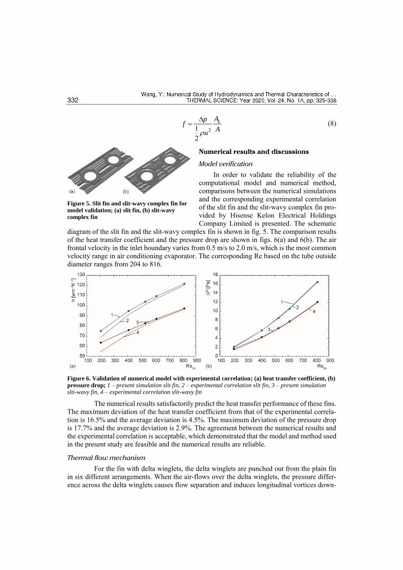
In order to validate the reliability of the computational model and numerical method, comparisons between the numerical simulations and the corresponding experimental correlation of the slit fin and the slit-wavy complex fin pro-vided by Hisense Kelon Electrical Holdings Company Limited is presented. The schematic
diagram of the slit fin and the slit-wavy complex fin is shown in fig. 5. The comparison results of the heat transfer coefficient and the pressure drop are shown in figs. 6(a) and 6(b). The air frontal velocity in the inlet boundary varies from 0.5 m/s to 2.0 m/s, which is the most common velocity range in air conditioning evaporator. The corresponding Re based on the tube outside diameter ranges from 204 to 816.
Figure 6. Validation of numerical model with experimental correlation; (a) heat transfer coefficient, (b)
pressure drop; 1 – present simulation slit fin, 2 – experimental correlation slit fin, 3 – present simulation slti-wavy fin, 4 – experimental correlation slit-wavy fin
The numerical results satisfactorily predict the heat transfer performance of these fins. The maximum deviation of the heat transfer coefficient from that of the experimental correla-tion is 16.5% and the average deviation is 4.5%. The maximum deviation of the pressure drop is 17.7% and the average deviation is 2.9%. The agreement between the numerical results and the experimental correlation is acceptable, which demonstrated that the model and method used in the present study are feasible and the numerical results are reliable.
Thermal flow mechanism
For the fin with delta winglets, the delta winglets are punched out from the plain fin in six different arrangements. When the air-flows over the delta winglets, the pressure differ-ence across the delta winglets causes flow separation and induces longitudinal vortices down-
Figure 5. Slit fin and slit-wavy complex fin for
model validation; (a) slit fin, (b) slit-wavy complex fin
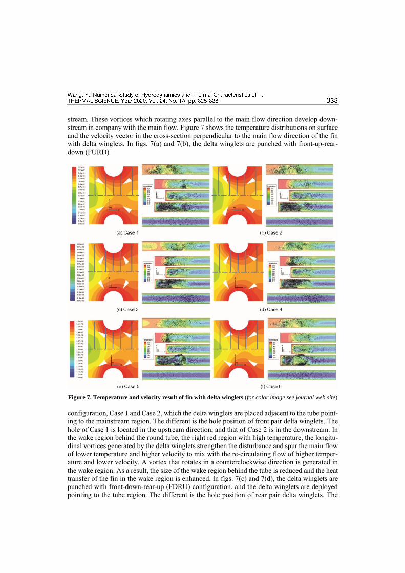
stream. These vortices which rotating axes parallel to the main flow direction develop down-stream in company with the main flow. Figure 7 shows the temperature distributions on surface and the velocity vector in the cross-section perpendicular to the main flow direction of the fin with delta winglets. In figs. 7(a) and 7(b), the delta winglets are punched with front-up-rear-down (FURD)
Figure 7. Temperature and velocity result of fin with delta winglets (for color image see journal web site)
configuration, Case 1 and Case 2, which the delta winglets are placed adjacent to the tube point-ing to the mainstream region. The different is the hole position of front pair delta winglets. The hole of Case 1 is located in the upstream direction, and that of Case 2 is in the downstream. In the wake region behind the round tube, the right red region with high temperature, the longitu-dinal vortices generated by the delta winglets strengthen the disturbance and spur the main flow of lower temperature and higher velocity to mix with the re-circulating flow of higher temper-ature and lower velocity. A vortex that rotates in a counterclockwise direction is generated in the wake region. As a result, the size of the wake region behind the tube is reduced and the heat transfer of the fin in the wake region is enhanced. In figs. 7(c) and 7(d), the delta winglets are punched with front-down-rear-up (FDRU) configuration, and the delta winglets are deployed pointing to the tube region. The different is the hole position of rear pair delta winglets. The

hole of Case 3 is located in the upstream direction, and that of Case 4 is in the downstream. The longitudinal vortices generated by the delta winglets direct main flow into the wake region with the right red region. On the other hand, the slender delta winglets and the tube form a nozzle-like passage, thus the fluid is accelerated in this passage and flows into the wake region behind the tube. In addition, a rotating vortex is generated in the wake region where the air is disturbed, and the heat transfer coefficient of the fin surface around this zone is enhanced. In figs. 7(e) and 7(f), the delta winglets are punched with traditional arrangement CFD and CFU, respec-tively. All the holes are located in the downstream direction. As can be seen in the figures, this two arrangement forms have great effect on performance, temperature and velocity distributions have the very big difference with each other. Generally, due to the longitudinal vortices gener-ated by the delta winglets, the heat transfer of the fin in the wake region is enhanced.
Heat transfer and pressure drop
Figure 8(a) shows the comparison of the heat transfer coefficient for the wavy fin and six different fins. The heat transfer performances of the structure optimized fins are superior to that of the wavy fin. The heat transfer coefficients of the fin with delta winglets are better than that of the wavy fin under all Reynolds numbers. In the Reynolds number range of the present study, compared with the wavy fin, the heat transfer coefficient increases by 9.6~32.7%, 8.6~30.0%, 12.7~37.5%, 13.3~34.8%, 12.2~33.1%, and 7.7~34.2% for the fin with delta wing-lets in FURD (Cases 1 and 2), FDRU (Cases 3 and 4), CFD (Case 5) and CFU (Case 6), respec-tively. The configuration has some influence on the heat transfer performance of the fin with delta winglets, and the heat transfer enhancement of the fin with delta winglets in FDRU is the best configuration.
Figure 8. Comparison of j-Colburn and friction factor; (a) j-Colburn factor, (b) friction factor
(for color image see journal web site)
The heat transfer characteristics are changed by optimized fin and meanwhile, the corresponding fluid-flow characteristics are also changed. Figure 8(b) shows the comparison of the pressure drop for the five different fins. It is interesting to note that the pressure drop of the fin with delta winglets in all configurations studied in this paper is less than that of the wavy fin. For the Reynolds number ranging from 204 to 2034, compared to the wavy fin, the pressure drop decreases by 6.0~17.1%, 5.4~15.6%, –7.5~3.7%, –7.4~3.3%, –4.0~6.3%, and –3.0~2.6% for the fin with delta winglets in Case 1 to Case 6, respectively. The delta winglet configuration has a great influence on the pressure drop penalty of the fin with delta winglets, and the pressure
drop of the FURD is much less than that of the other configurations. The delta winglets signif-icantly enhance the heat transfer of the fin by the longitudinal vortices generated downstream. Moreover, the increase of the pressure drop penalty induced by the delta winglets is relatively small. The delta winglet is very promising for enhancing the performance of the heat exchang-ers. In addition, Base on the above analysis, the traditional CFD and CFU arrangements are not the best in both heat transfer and flow resistance performance.
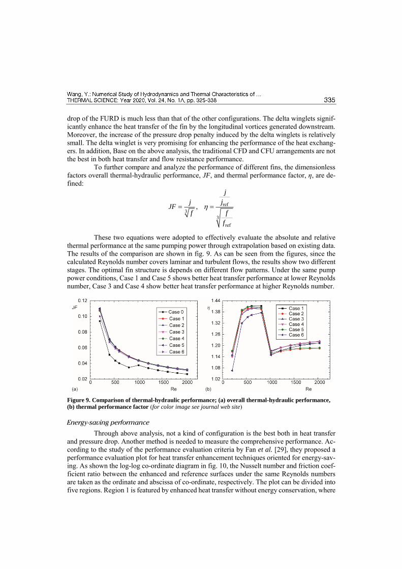
To further compare and analyze the performance of different fins, the dimensionless factors overall thermal-hydraulic performance, JF, and thermal performance factor, η, are de-fined:
ref3
3ref
,
j
jjJF
f f
f
These two equations were adopted to effectively evaluate the absolute and relative thermal performance at the same pumping power through extrapolation based on existing data. The results of the comparison are shown in fig. 9. As can be seen from the figures, since the calculated Reynolds number covers laminar and turbulent flows, the results show two different stages. The optimal fin structure is depends on different flow patterns. Under the same pump power conditions, Case 1 and Case 5 shows better heat transfer performance at lower Reynolds number, Case 3 and Case 4 show better heat transfer performance at higher Reynolds number.
Figure 9. Comparison of thermal-hydraulic performance; (a) overall thermal-hydraulic performance, (b) thermal performance factor (for color image see journal web site)
Energy-saving performance
Through above analysis, not a kind of configuration is the best both in heat transfer and pressure drop. Another method is needed to measure the comprehensive performance. Ac-cording to the study of the performance evaluation criteria by Fan et al. [29], they proposed a performance evaluation plot for heat transfer enhancement techniques oriented for energy-sav-ing. As shown the log-log co-ordinate diagram in fig. 10, the Nusselt number and friction coef-ficient ratio between the enhanced and reference surfaces under the same Reynolds numbers are taken as the ordinate and abscissa of co-ordinate, respectively. The plot can be divided into five regions. Region 1 is featured by enhanced heat transfer without energy conservation, where
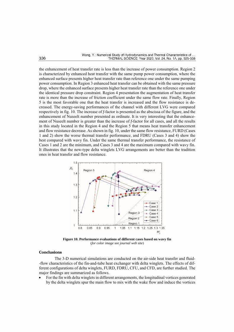
the enhancement of heat transfer rate is less than the increase of power consumption. Region 2 is characterized by enhanced heat transfer with the same pump power consumption, where the enhanced surface presents higher heat transfer rate than reference one under the same pumping power consumption. In Region 3 enhanced heat transfer can be obtained with the same pressure drop, where the enhanced surface presents higher heat transfer rate than the reference one under the identical pressure drop constraint. Region 4 presentation the augmentation of heat transfer rate is more than the increase of friction coefficient under the same flow rate. Finally, Region 5 is the most favorable one that the heat transfer is increased and the flow resistance is de-creased. The energy-saving performances of the channel with different LVG were compared respectively in fig. 10. The increase of f-factor is presented as the abscissa of the figure, and the enhancement of Nuseelt number presented as ordinate. It is very interesting that the enhance-ment of Nuseelt number is greater than the increase of f-factor for all cases, and all the results in this study located in the Region 4 and the Region 5 that means heat transfer enhancement and flow resistance decrease. As shown in fig. 10, under the same flow resistance, FURD (Cases 1 and 2) show the worse thermal transfer performance, and FDRU (Cases 3 and 4) show the best compared with wavy fin. Under the same thermal transfer performance, the resistance of Cases 1 and 2 are the minimum, and Cases 3 and 4 are the maximum compared with wavy fin. It illustrates that the new-type delta winglets LVG arrangements are better than the tradition ones in heat transfer and flow resistance.
Figure 10. Performance evaluations of different cases based on wavy fin
(for color image see journal web site)
Conclusions
The 3-D numerical simulations are conducted on the air-side heat transfer and fluid- -flow characteristics of the fin-and-tube heat exchanger with delta winglets. The effects of dif-ferent configurations of delta winglets, FURD, FDRU, CFU, and CFD, are further studied. The major findings are summarized as follows. For the fin with delta winglets in different arrangements, the longitudinal vortices generated
by the delta winglets spur the main flow to mix with the wake flow and induce the vortices

in the wake region behind the tube. Consequently, the heat transfer in wake region is en-hanced.
Compared with the wavy fin, the heat transfer j-factor increases by 9.5~36.5%, 8.6~34.6%, 13.3~40.2%, 13.4~41.9%, 12.1~37.4%, and 7.5~38.5% for the fin with delta winglets in Case 1 to Case 6, respectively. Moreover, the pressure drop penalty induced by the delta winglets is relatively small. The f-factor increases by –13.1~16.0%, –19.5~17.0%, –4.2~28.2%, –1.5~32.4%, –12.4~21.4%, and 1.9~29.8%, respectively.
The delta winglet applied in the fin is a very promising heat transfer enhancement technol-ogy for fin-and-tube compact heat exchanger. The distinction of the integrative perfor-mance between the fin with delta winglets in different configuration is significant. The fin with FURD delta winglets is better at lower Re number, which shows small flow resistance, and that with FDRU is better at higher Re number, which shows great heat transfer.
Acknowledgment
This work has been supported by the National Natural Science Foundation of China (No. 51806177).
References
[1] Bergles, A. E., Handbook of heat transfer applications, McGraw-Hill, New York, USA, 1985 [2] Bergles, A. E., ExHFT for Fourth Generation Heat Transfer Technology, Experimental Thermal and Fluid
Science, 26 (2002), 2-4, pp. 335-344 [3] Jacobi, A. M., Shah, R. K., Heat Transfer Surface Enhancement through the Use of Longitudinal Vortices:
A review of Recent Progress, Experimental Thermal and Fluid Science, 11(1995), 3, pp. 295-309 [4] Fiebig, M., Embedded Vortices in Internal Flow-Heat-Transfer and Pressure Loss Enhancement, Interna-
tional Journal of Heat and Fluid Flow, 16 (1995), 5, pp. 376-388 [5] Johnson, T. R., Joubert, P. N., The Influence of Vortex Generators on Drag and Heat Transfer from a
Circular Cylinder Normal to an Airstream, Journal of Heat Transfer-Transactions of the ASME, 91 (1969), 1, pp. 91-99
[6] Biswas, G., et al., Heat Transfer Enhancement in Fin-Tube Heat Exchangers by Winglet Type Vortex Generators, International Journal of Heat and Mass Transfer, 37 (1994), 2, pp. 283-291
[7] Torii, K., et al., Heat Transfer Enhancement Accompanying Pressure-Loss Reduction with Winglet-Type Vortex Generators for Fin-Tube Heat Exchangers, International Journal of Heat and Mass Transfer, 45 (2002), 18, pp. 3795-3801
[8] Jain, A., et al., Winglet-Type Vortex Generators with Common-Flow-Up Configuration for Fin-Tube Heat Exchangers, Numerical Heat Transfer Part a-Applications, 43 (2003), 2, pp. 201-219
[9] O'Brien, J. E., Sohal, M. S., Heat Transfer Enhancement For Finned-Tube Heat Exchangers with Winglets, Journal of Heat Transfer-Transactions of the ASME, 127 (2005), 2, pp. 171-178
[10] Pesteei, S. M., et al., Experimental Study of the Effect of Winglet Location on Heat Transfer Enhancement and Pressure Drop in Fin-Tube Heat Exchangers, Applied Thermal Engineering, 25 (2005), 11-12, pp. 1684-1696
[11] Joardar, A., Jacobi, A. M., A Numerical Study of Flow and Heat Transfer Enhancement Using an Array of Delta-Winglet Vortex Generators in a Fin-and-Tube Heat Exchanger, Journal of Heat Transfer-Trans-actions of the ASME, 129 (2007), 9, pp. 1156-1167
[12] Joardar, A., Jacobi, A. M., Heat Transfer Enhancement by Winglet-Type Vortex Generator Arrays in Compact Plain-Fin-and-Tube HEAT exchangers, International Journal of Refrigeration-Revue Interna-tionale Du Froid, 31 (2008), 1, pp. 87-97
[13] Tian, L. T., et al., Numerical Study of Fluid Flow and Heat Transfer in a Flat-Plate Channel with Longi-tudinal Vortex Generators by Applying Field Synergy Principle Analysis, International Communications in Heat and Mass Transfer, 36 (2009), 2, pp. 111-120
[14] Lei, Y. G., et al., Hydrodynamics and Heat Transfer Characteristics of a Novel Heat Exchanger with Delta-Winglet Vortex Generators, Chemical Engineering Science, 65 (2010), 5, pp. 1551-1562

[15] Chu, P., et al., Three-Dimensional Numerical Study of Flow and Heat Transfer Enhancement Using Vor-tex Generators in Fin-and-Tube Heat Exchangers, Journal of Heat Transfer-Transactions of the ASME, 131 (2009), 9, pp. 091903
[16] Chu, P., et al., Three-Dimensional Numerical Study on Fin-and-Oval-Tube Heat Exchanger with Longi-tudinal Vortex Generators, Applied Thermal Engineering, 29 (2009), 5-6, pp. 859-876
[17] Tang, L. H., et al., Experimental and Numerical Investigation on Air-Side Performance of Fin-and-Tube Heat Exchangers with Various Fin Patterns, Experimental Thermal and Fluid Science, 33 (2009), 5, pp. 818-827
[18] Wu, J. M., et al., Impact of Delta Winglet Vortex Generators on the Performance of a Novel Fin-Tube Surfaces with Two Rows of Tubes in Different Diameters, Energy Conversion and Management, 52 (2011), 8-9, pp. 2895-2901
[19] Wu, J. M., et al., Experimental Study on the Performance of a Novel Fin-Tube Air Heat Exchanger with Punched Longitudinal Vortex Generator, Energy Conversion and Management, 57 (2012), May, pp. 42-48
[20] Du, X. P., et al., An Experimental Investigation on Air-Side Performances of Finned Tube Heat Exchang-ers for Indirect Air-Cooling Tower, Thermal Science, 18 (2014), 3, pp. 863-874
[21] Gholami, A. A., et al., Heat Transfer Enhancement and Pressure Drop for Fin-and-Tube Compact Heat Exchangers with Wavy Rectangular Winglet-Type Vortex Generators, International Communications in Heat and Mass Transfer, 54 (2014), May, pp. 132-140
[22] Lotfi, B., et al., An Investigation of the Thermo-Hydraulic Performance of the Smooth Wavy Fin-And-Elliptical Tube Heat Exchangers Utilizing New Type Vortex Generators, Applied Energy, 126 (2016), Jan., pp. 1282-1302
[23] Bhuiyan, A. A., Islam, A. K. M., Thermal and Hydraulic Performance of Finned-Tube Heat Exchangers Under Different Flow Ranges: A Review on Modeling and Experiment, International Journal of Heat and Mass Transfer, 101 (2016), Oct., pp. 38-59
[24] Deng, J., Qian, Z. Q., Simplified Analysis of Thermal Contact Resistance on Arc-Slotted Fin Core, Applied Thermal Engineering, 125 (2017), Oct., pp. 266-284
[25] Sarangi, S. K., Mishra, D. P., Effect of Winglet Location on Heat Transfer of a Fin-and-Tube Heat Ex-changer, Applied Thermal Engineering, 116 (2017), Apr., pp. 528-540
[26] Gholami, A., et al., Thermal-Hydraulic Performance of Fin-And-Oval Tube Compact Heat Exchangers with Innovative Design of Corrugated Fin Patterns, International Journal of Heat and Mass Transfer, 106 (2017), Mar., pp. 573-592
[27] Valikangas, T., et al T., Fin-and-Tube Heat Exchanger Enhancement with a Combined Herringbone and Vortex Generator Design, International Journal of Heat and Mass Transfer, 118 (2018), Mar., pp. 602-616
[28] Tao, W. Q., Numerical Heat Transfer, Xi'an Jiaotong University Press, Xi'an, China, 2001 [29] Fan, J. F., et al., A Performance Evaluation Plot of Enhanced Heat Transfer Techniques Oriented for
Energy-Saving, International Journal of Heat and Mass Transfer, 52 (2009), 1-2, pp. 33-44
Paper submitted: March 30, 2019 © 2020 Society of Thermal Engineers of Serbia. Paper revised: August 22, 2019 Published by the Vinča Institute of Nuclear Sciences, Belgrade, Serbia. Paper accepted: August 24, 2019 This is an open access article distributed under the CC BY-NC-ND 4.0 terms and conditions.