numerical vpc ceoncept
TRANSCRIPT
11-1
Chapter 11 REFRIGERATION CYCLES
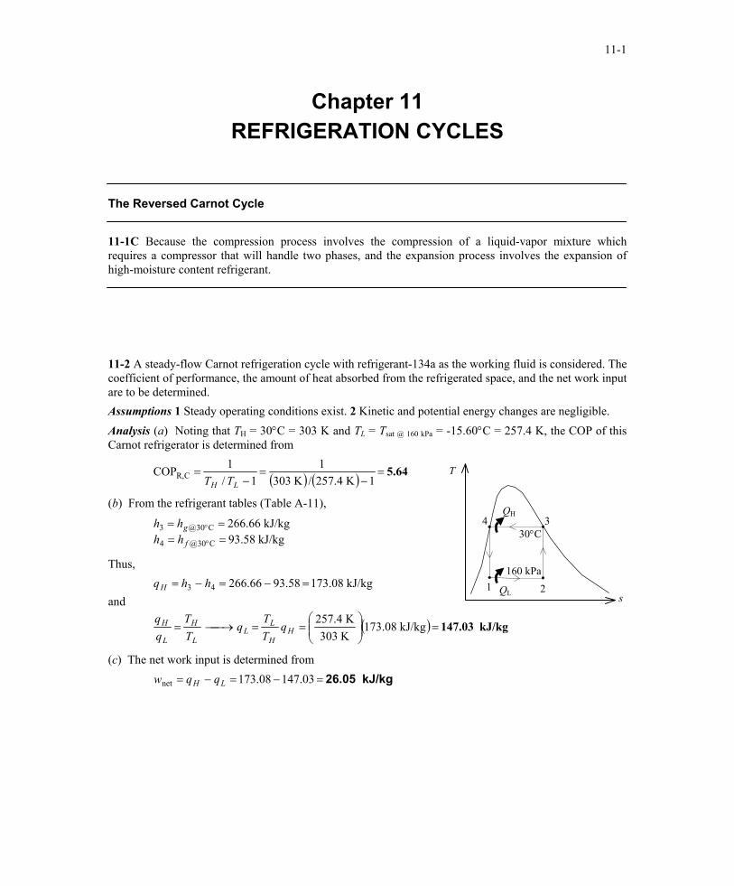
The Reversed Carnot Cycle 11-1C Because the compression process involves the compression of a liquid-vapor mixture which requires a compressor that will handle two phases, and the expansion process involves the expansion of high-moisture content refrigerant. 11-2 A steady-flow Carnot refrigeration cycle with refrigerant-134a as the working fluid is considered. The coefficient of performance, the amount of heat absorbed from the refrigerated space, and the net work input are to be determined. Assumptions 1 Steady operating conditions exist. 2 Kinetic and potential energy changes are negligible. Analysis (a) Noting that TH = 30°C = 303 K and TL = Tsat @ 160 kPa = -15.60°C = 257.4 K, the COP of this Carnot refrigerator is determined from
( ) ( ) 5.64=−
=−
=1K 4.257/K 303
11/
1COP CR,LH TT
(b) From the refrigerant tables (Table A-11),
kJ/kg 58.93kJ/kg 66.266
C30@4
C30@3====
°
°
f
ghhhh
Thus,
and
( ) kJ/kg 147.03=
==→=
=−=−=
kJ/kg 173.08K 303K 257.4
kJ/kg 08.17358.9366.26643
HH
LL
L
H
L
H
H
qTT
qTT
hhq
30°C 4 3
2 1160 kPa
QL
QH
T
s
(c) The net work input is determined from kJ/kg 26.05=−=−= 03.14708.173net LH qqw
PROPRIETARY MATERIAL. © 2006 The McGraw-Hill Companies, Inc. Limited distribution permitted only to teachers and educators for course preparation. If you are a student using this Manual, you are using it without permission.
11-2
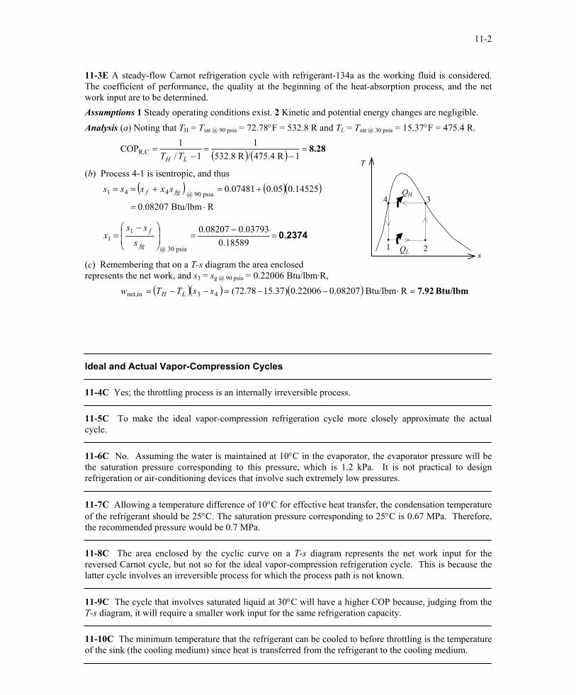
11-3E A steady-flow Carnot refrigeration cycle with refrigerant-134a as the working fluid is considered. The coefficient of performance, the quality at the beginning of the heat-absorption process, and the net work input are to be determined. Assumptions 1 Steady operating conditions exist. 2 Kinetic and potential energy changes are negligible. Analysis (a) Noting that TH = Tsat @ 90 psia = 72.78°F = 532.8 R and TL = Tsat @ 30 psia = 15.37°F = 475.4 R.
( ) ( ) 8.28=−
=−
=1R 475.4/R 532.8
11/
1COP CR,LH TT
(b) Process 4-1 is isentropic, and thus
( ) ( )( )
0.2374=−
=
−=
⋅=
+=+==
18589.003793.008207.0
RBtu/lbm 0.08207
14525.005.007481.0
psia 30 @
11
psia 90 @ 441
fg
f
fgf
sss
x
sxsss
(c) Remembering that on a T-s diagram the area enclosed represents the net work, and s3 = sg @ 90 psia = 0.22006 Btu/lbm·R, ( )( ) ( ) Btu/lbm7.92 RBtu/lbm 08207.022006.0)37.1578.72(43innet, =⋅−−=−−= ssTTw LH
Ideal and Actual Vapor-Compression Cycles 11-4C Yes; the throttling process is an internally irreversible process. 11-5C To make the ideal vapor-compression refrigeration cycle more closely approximate the actual cycle. 11-6C No. Assuming the water is maintained at 10°C in the evaporator, the evaporator pressure will be the saturation pressure corresponding to this pressure, which is 1.2 kPa. It is not practical to design refrigeration or air-conditioning devices that involve such extremely low pressures. 11-7C Allowing a temperature difference of 10°C for effective heat transfer, the condensation temperature of the refrigerant should be 25°C. The saturation pressure corresponding to 25°C is 0.67 MPa. Therefore, the recommended pressure would be 0.7 MPa. 11-8C The area enclosed by the cyclic curve on a T-s diagram represents the net work input for the reversed Carnot cycle, but not so for the ideal vapor-compression refrigeration cycle. This is because the latter cycle involves an irreversible process for which the process path is not known. 11-9C The cycle that involves saturated liquid at 30°C will have a higher COP because, judging from the T-s diagram, it will require a smaller work input for the same refrigeration capacity.
QH
QL
4 3
21
T
s
11-10C The minimum temperature that the refrigerant can be cooled to before throttling is the temperature of the sink (the cooling medium) since heat is transferred from the refrigerant to the cooling medium.
PROPRIETARY MATERIAL. © 2006 The McGraw-Hill Companies, Inc. Limited distribution permitted only to teachers and educators for course preparation. If you are a student using this Manual, you are using it without permission.
11-3
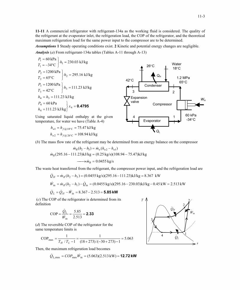
11-11 A commercial refrigerator with refrigerant-134a as the working fluid is considered. The quality of the refrigerant at the evaporator inlet, the refrigeration load, the COP of the refrigerator, and the theoretical maximum refrigeration load for the same power input to the compressor are to be determined. Assumptions 1 Steady operating conditions exist. 2 Kinetic and potential energy changes are negligible. Analysis (a) From refrigerant-134a tables (Tables A-11 through A-13)
0.4795=
==
==
=
°==
=
°==
=
°−==
44
4
34
33
3
22
2
11
1
kJ/kg 23.111kPa 60
kJ/kg 23.111
kJ/kg 23.111C42
kPa 1200
kJ/kg 16.295C65
kPa 1200
kJ/kg 03.230C34
kPa 60
xhP
hh
hTP
hTP
hTP
26°C Water 18°C
Win
QL
1.2 MPa 65°C
Expansion valve
Compressor
Evaporator
Condenser 42°C
QH
4
3 2
1 60 kPa -34°C
Using saturated liquid enthalpy at the given temperature, for water we have (Table A-4)
kJ/kg 94.108
kJ/kg 47.75
C26 @2
C18 @1
==
==
°
°
fw
fw
hh
hh
(b) The mass flow rate of the refrigerant may be determined from an energy balance on the compressor
kg/s 0455.0
g75.47)kJ/k94kg/s)(108. (0.25kJ/kg)23.11116.295()()( 1232
=→
−=−−=−
R
R
wwwR
m
mhhmhhm
&
&
&&
The waste heat transferred from the refrigerant, the compressor power input, and the refrigeration load are
kW 367.8kJ/kg)23.11116kg/s)(295. 0455.0()( 32 =−=−= hhmQ RH &&
kW 513.2kW 0.45kJ/kg)03.23016kg/s)(295. 0455.0()( in12in =−−=−−= QhhmW R&&&
kW 5.85=−=−= 513.2367.8inWQQ HL&&&
(c) The COP of the refrigerator is determined from its definition
T
QH
QL
Win·
2
·
·
4
3
2
1
2.33===513.285.5COP
in
L
WQ&
&
(d) The reversible COP of the refrigerator for the same temperature limits is
063.51)27330/()27318(
11/
1COPmax =−+−+
=−
=LH TT
s
Then, the maximum refrigeration load becomes
kW 12.72=== kW) 513.2)(063.5(inmaxmaxL, WCOPQ &&
PROPRIETARY MATERIAL. © 2006 The McGraw-Hill Companies, Inc. Limited distribution permitted only to teachers and educators for course preparation. If you are a student using this Manual, you are using it without permission.

11-4
11-12 An ideal vapor-compression refrigeration cycle with refrigerant-134a as the working fluid is considered. The rate of heat removal from the refrigerated space, the power input to the compressor, the rate of heat rejection to the environment, and the COP are to be determined. Assumptions 1 Steady operating conditions exist. 2 Kinetic and potential energy changes are negligible. Analysis (a) In an ideal vapor-compression refrigeration cycle, the compression process is isentropic, the refrigerant enters the compressor as a saturated vapor at the evaporator pressure, and leaves the condenser as saturated liquid at the condenser pressure. From the refrigerant tables (Tables A-12 and A-13),
( )
( )throttlingkJ/kg 82.88
kJ/kg 82.88liquid sat.
MPa 7.0
C95.34kJ/kg 50.273MPa 7.0
KkJ/kg 94779.0kJ/kg 97.236
vaporsat.kPa 120
34
MPa 7.0 @ 33
2212
2
kPa 120 @ 1
kPa 120 @ 11
=≅
===
°==
==
⋅====
=
hh
hhP
Thss
P
sshhP
f
g
g
T
QH
QL 4s
·
Win·
·
0.7 MPa
4
32
1 0.12 MPa
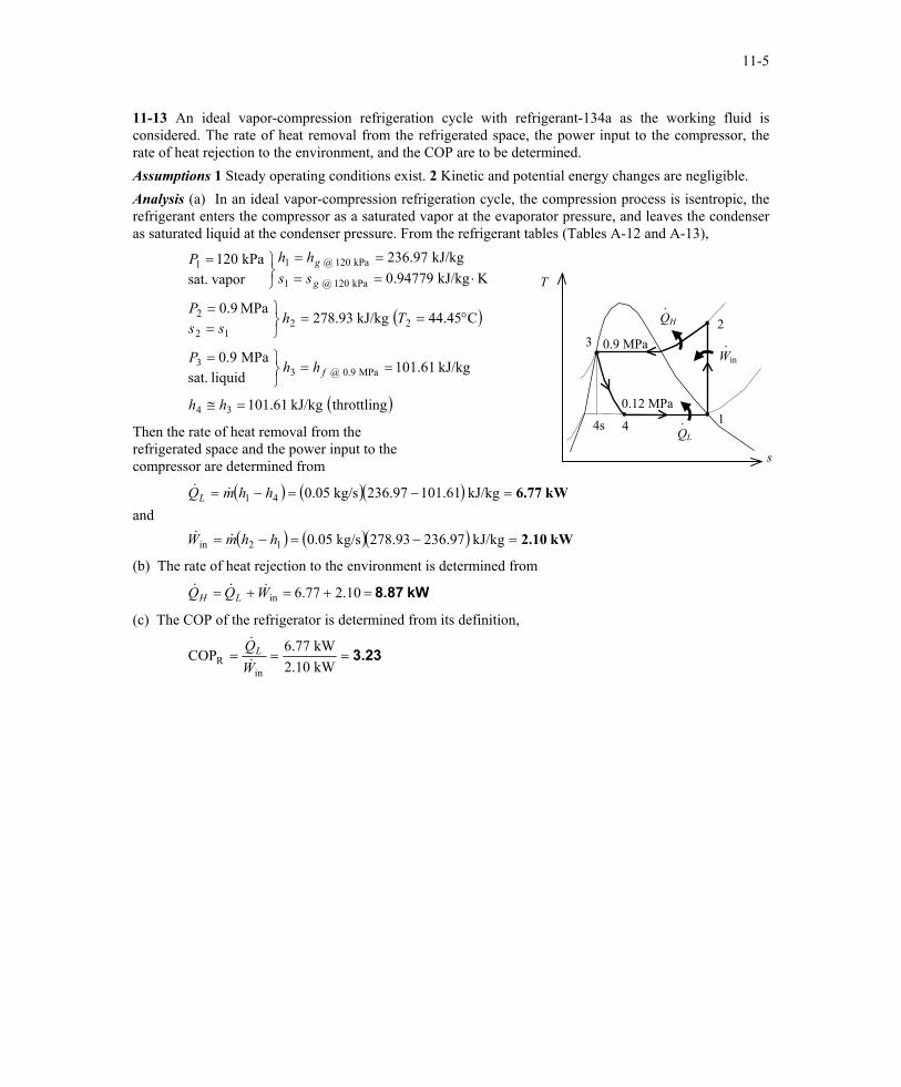
Then the rate of heat removal from the refrigerated space and the power input to the compressor are determined from
s
and ( ) ( )( )
( ) ( )( ) kW 1.83
kW 7.41
=−=−=
=−=−=
kJ/kg 236.97273.50kg/s 0.05
kJ/kg 82.8897.236kg/s 0.05
12in
41
hhmW
hhmQL
&&
&&
(b) The rate of heat rejection to the environment is determined from
kW 9.23=+=+= 83.141.7inWQQ LH&&&
(c) The COP of the refrigerator is determined from its definition,
4.06===kW 1.83kW 7.41COP
inR W
QL&
&
PROPRIETARY MATERIAL. © 2006 The McGraw-Hill Companies, Inc. Limited distribution permitted only to teachers and educators for course preparation. If you are a student using this Manual, you are using it without permission.
11-5
11-13 An ideal vapor-compression refrigeration cycle with refrigerant-134a as the working fluid is considered. The rate of heat removal from the refrigerated space, the power input to the compressor, the rate of heat rejection to the environment, and the COP are to be determined. Assumptions 1 Steady operating conditions exist. 2 Kinetic and potential energy changes are negligible. Analysis (a) In an ideal vapor-compression refrigeration cycle, the compression process is isentropic, the refrigerant enters the compressor as a saturated vapor at the evaporator pressure, and leaves the condenser as saturated liquid at the condenser pressure. From the refrigerant tables (Tables A-12 and A-13),
( )
( )throttlingkJ/kg 61.101
kJ/kg 61.101liquid sat.
MPa 9.0
C45.44kJ/kg 93.278MPa 9.0
KkJ/kg 94779.0kJ/kg 97.236
vaporsat.kPa 120
34
MPa 9.0 @ 33
2212
2
kPa 120 @ 1
kPa 120 @ 11
=≅
===
°==
==
⋅====
=
hh
hhP
Thss
P
sshhP
f
g
g
T
QH
QL 4s
·
Win·
·
0.9 MPa
4
32
1 0.12 MPa
Then the rate of heat removal from the refrigerated space and the power input to the compressor are determined from s
and ( ) ( )( )
( ) ( )( ) kW2.10
kW 6.77
kJ/kg 236.97278.93kg/s 0.05
kJ/kg 61.10197.236kg/s 0.05
12in
41
=−=−=
=−=−=
hhmW
hhmQL
&&
&&
(b) The rate of heat rejection to the environment is determined from
kW 8.87=+=+= 10.277.6inWQQ LH&&&
(c) The COP of the refrigerator is determined from its definition,
3.23===kW 2.10kW 6.77COP
inR W
QL&
&
PROPRIETARY MATERIAL. © 2006 The McGraw-Hill Companies, Inc. Limited distribution permitted only to teachers and educators for course preparation. If you are a student using this Manual, you are using it without permission.
11-6
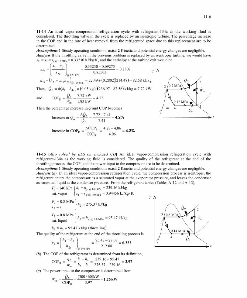
11-14 An ideal vapor-compression refrigeration cycle with refrigerant-134a as the working fluid is considered. The throttling valve in the cycle is replaced by an isentropic turbine. The percentage increase in the COP and in the rate of heat removal from the refrigerated space due to this replacement are to be determined. Assumptions 1 Steady operating conditions exist. 2 Kinetic and potential energy changes are negligible. Analysis If the throttling valve in the previous problem is replaced by an isentropic turbine, we would have s4s = s3 = sf @ 0.7 MPa = 0.33230 kJ/kg·K, and the enthalpy at the turbine exit would be
( ) ( )( ) kJ/kg 58.8248.2142802.049.22
2802.085503.0
09275.033230.0
kPa 120 @44
kPa 120 @
34
=+=+=
=−
=
−=
fgsfs
fg
fs
hxhh
sss
x T
QH
QL 4s
·
Win ·
·
0.7 MPa
4
32
10.12 MPa
Then, Q ( ) ( )( ) kW 7.72kJ/kg 82.58236.97kg/s 0.0541 =−=−= sL hhm&&
and 23.4kW 1.83kW 7.72COP
inR ===
WQL&
&
Then the percentage increase in and COP becomes &Q
4.2%
4.2%
=−
=∆
=
=−
=∆
=
06.406.423.4
COPCOP
COPin Increase
41.741.772.7in Increase
R
RR
L
LL Q
&
&&
s
11-15 [Also solved by EES on enclosed CD] An ideal vapor-compression refrigeration cycle with refrigerant-134a as the working fluid is considered. The quality of the refrigerant at the end of the throttling process, the COP, and the power input to the compressor are to be determined. Assumptions 1 Steady operating conditions exist. 2 Kinetic and potential energy changes are negligible. Analysis (a) In an ideal vapor-compression refrigeration cycle, the compression process is isentropic, the refrigerant enters the compressor as a saturated vapor at the evaporator pressure, and leaves the condenser as saturated liquid at the condenser pressure. From the refrigerant tables (Tables A-12 and A-13),
( )throttlingkJ/kg 47.95
kJ/kg 47.95liquid sat.
MPa 8.0
kJ/kg 37.275MPa 8.0
KkJ/kg 94456.0kJ/kg 16.239
vapor sat.kPa 140
34
MPa 8.0 @ 33
212
2
kPa 140 @ 1
kPa 140 @ 11
=≅
===
=
==
⋅====
=
hh
hhP
hss
P
sshhP
f
g
g
T
QH
QL
·
Win·
·
0.8 MPa
4
32
10.14 MPa
The quality of the refrigerant at the end of the throttling process is
0.322=−
=
−=
08.21208.2747.95
kPa 140 @
44
fg
f
hhh
x s
(b) The COP of the refrigerator is determined from its definition,
3.97=−−
=−−
==16.23937.275
47.9516.239COP12
41
inR hh
hhwqL
(c) The power input to the compressor is determined from
kW 1.26===97.3
kW)60/300(COPR
inLQ
W&
&
PROPRIETARY MATERIAL. © 2006 The McGraw-Hill Companies, Inc. Limited distribution permitted only to teachers and educators for course preparation. If you are a student using this Manual, you are using it without permission.
11-7
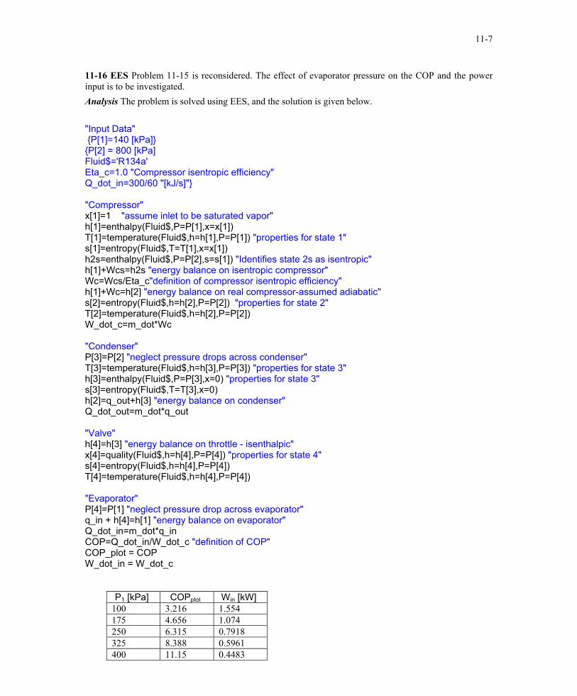
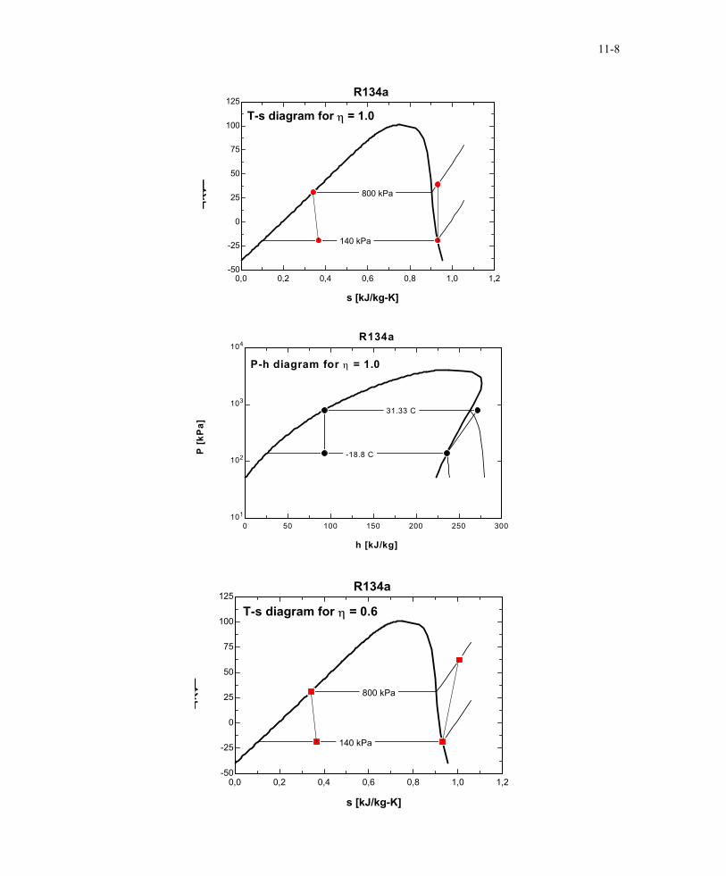
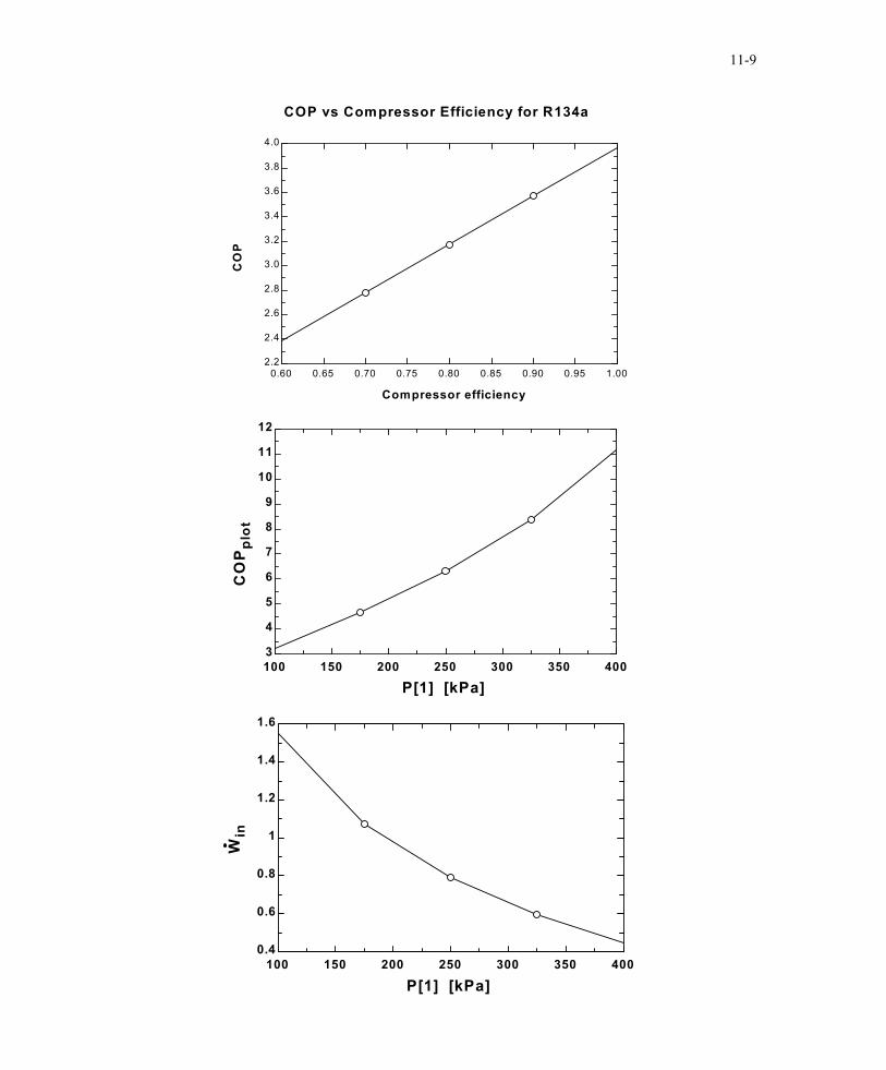
11-16 EES Problem 11-15 is reconsidered. The effect of evaporator pressure on the COP and the power input is to be investigated. Analysis The problem is solved using EES, and the solution is given below. "Input Data" {P[1]=140 [kPa]} {P[2] = 800 [kPa] Fluid$='R134a' Eta_c=1.0 "Compressor isentropic efficiency" Q_dot_in=300/60 "[kJ/s]"} "Compressor" x[1]=1 "assume inlet to be saturated vapor" h[1]=enthalpy(Fluid$,P=P[1],x=x[1]) T[1]=temperature(Fluid$,h=h[1],P=P[1]) "properties for state 1" s[1]=entropy(Fluid$,T=T[1],x=x[1]) h2s=enthalpy(Fluid$,P=P[2],s=s[1]) "Identifies state 2s as isentropic" h[1]+Wcs=h2s "energy balance on isentropic compressor" Wc=Wcs/Eta_c"definition of compressor isentropic efficiency" h[1]+Wc=h[2] "energy balance on real compressor-assumed adiabatic" s[2]=entropy(Fluid$,h=h[2],P=P[2]) "properties for state 2" T[2]=temperature(Fluid$,h=h[2],P=P[2]) W_dot_c=m_dot*Wc "Condenser" P[3]=P[2] "neglect pressure drops across condenser" T[3]=temperature(Fluid$,h=h[3],P=P[3]) "properties for state 3" h[3]=enthalpy(Fluid$,P=P[3],x=0) "properties for state 3" s[3]=entropy(Fluid$,T=T[3],x=0) h[2]=q_out+h[3] "energy balance on condenser" Q_dot_out=m_dot*q_out "Valve" h[4]=h[3] "energy balance on throttle - isenthalpic" x[4]=quality(Fluid$,h=h[4],P=P[4]) "properties for state 4" s[4]=entropy(Fluid$,h=h[4],P=P[4]) T[4]=temperature(Fluid$,h=h[4],P=P[4]) "Evaporator" P[4]=P[1] "neglect pressure drop across evaporator" q_in + h[4]=h[1] "energy balance on evaporator" Q_dot_in=m_dot*q_in COP=Q_dot_in/W_dot_c "definition of COP" COP_plot = COP W_dot_in = W_dot_c
P1 [kPa] COPplot Win [kW] 100 3.216 1.554 175 4.656 1.074 250 6.315 0.7918 325 8.388 0.5961 400 11.15 0.4483
PROPRIETARY MATERIAL. © 2006 The McGraw-Hill Companies, Inc. Limited distribution permitted only to teachers and educators for course preparation. If you are a student using this Manual, you are using it without permission.
11-8
0,0 0,2 0,4 0,6 0,8 1,0 1,2-50
-25
0
25
50
75
100
125
s [kJ/kg-K]
T[C]
800 kPa
140 kPa
R134a
T-s diagram for η = 1.0
0 50 100 150 200 250 300101
102
103
104
h [kJ/kg]
P [k
Pa]
31.33 C
-18.8 C
R134a
P-h diagram for η = 1.0
0,0 0,2 0,4 0,6 0,8 1,0 1,2-50
-25
0
25
50
75
100
125
s [kJ/kg-K]
T[C]
800 kPa
140 kPa
R134a
T-s diagram for η = 0.6
PROPRIETARY MATERIAL. © 2006 The McGraw-Hill Companies, Inc. Limited distribution permitted only to teachers and educators for course preparation. If you are a student using this Manual, you are using it without permission.
11-9
0.60 0.65 0.70 0.75 0.80 0.85 0.90 0.95 1.002.2
2.4
2.6
2.8
3.0
3.2
3.4
3.6
3.8
4.0
Compressor efficiency
CO
P
COP vs Compressor Efficiency for R134a
100 150 200 250 300 350 4003
4
5
6
7
8
9
10
11
12
P[1] [kPa]
CO
Ppl
ot
100 150 200 250 300 350 4000.4
0.6
0.8
1
1.2
1.4
1.6
P[1] [kPa]
Win
PROPRIETARY MATERIAL. © 2006 The McGraw-Hill Companies, Inc. Limited distribution permitted only to teachers and educators for course preparation. If you are a student using this Manual, you are using it without permission.
11-10
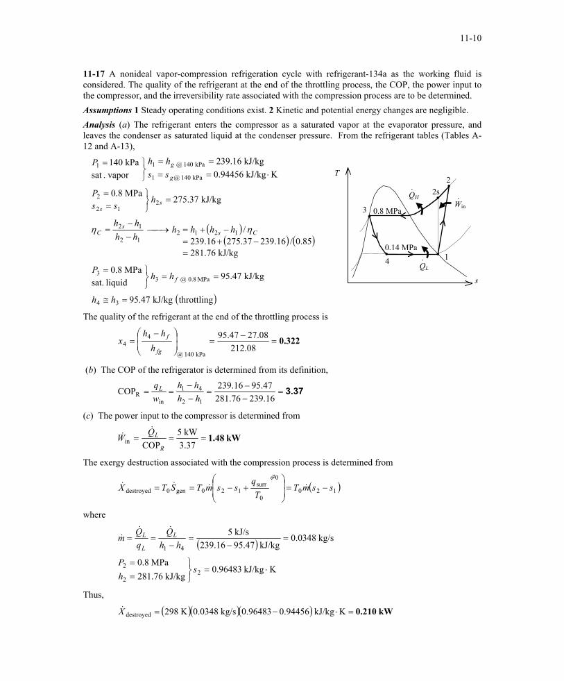
11-17 A nonideal vapor-compression refrigeration cycle with refrigerant-134a as the working fluid is considered. The quality of the refrigerant at the end of the throttling process, the COP, the power input to the compressor, and the irreversibility rate associated with the compression process are to be determined. Assumptions 1 Steady operating conditions exist. 2 Kinetic and potential energy changes are negligible. Analysis (a) The refrigerant enters the compressor as a saturated vapor at the evaporator pressure, and leaves the condenser as saturated liquid at the condenser pressure. From the refrigerant tables (Tables A-12 and A-13),
( )( )
( )throttlingkJ/kg 47.95
kJ/kg 47.95liquid sat.
MPa 8.0
kJ/kg 76.28185.0/16.23937.27516.239
/
kJ/kg 37.275MPa 8.0
KkJ/kg 94456.0kJ/kg 16.239
vapor.sat kPa 140
34
MPa 8.0 @ 33
121212
12
212
2
kPa 140 @1
kPa 140 @ 11
=≅
===
=−+=
−+=→−−
=
=
==
⋅====
=
hh
hhP
hhhhhhhh
hss
P
sshhP
f
Css
C
ss
g
g
ηη ( )
T2
QH · 2s
Win·
3 0.8 MPa
0.14 MPa1
QL ·4
s
The quality of the refrigerant at the end of the throttling process is
0.322=−
=
−=
08.21208.2747.95
kPa 140 @
44
fg
f
hhh
x
(b) The COP of the refrigerator is determined from its definition,
3.37=−−
=−−
==16.23976.281
47.9516.239COP12
41
inR hh
hhwqL
(c) The power input to the compressor is determined from
kW 1.48===37.3kW 5
COPinR
LQW
&&
The exergy destruction associated with the compression process is determined from
( )120
0
0
surr120gen0destroyed ssmT
Tq
ssmTSTX −=
+−== &&&&
where
( )
KkJ/kg 96483.0kJ/kg 76.281
MPa 8.0
kg/s 0348.0kJ/kg 95.47239.16
kJ/s 5
22
2
41
⋅=
==
=−
=−
==
shP
hhQ
m L
L
L&&
&
Thus,
( )( )( ) kW 0.210=⋅−= KkJ/kg 0.944560.96483kg/s 0.0348K 298destroyedX&
PROPRIETARY MATERIAL. © 2006 The McGraw-Hill Companies, Inc. Limited distribution permitted only to teachers and educators for course preparation. If you are a student using this Manual, you are using it without permission.
11-11
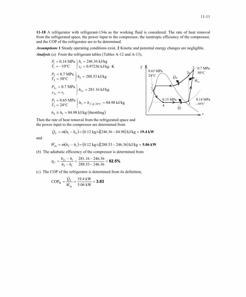
11-18 A refrigerator with refrigerant-134a as the working fluid is considered. The rate of heat removal from the refrigerated space, the power input to the compressor, the isentropic efficiency of the compressor, and the COP of the refrigerator are to be determined. Assumptions 1 Steady operating conditions exist. 2 Kinetic and potential energy changes are negligible. Analysis (a) From the refrigerant tables (Tables A-12 and A-13),
( )throttlingkJ/kg 98.84
kJ/kg 98.84C24MPa 65.0
kJ/kg 16.281MPa 7.0
kJ/kg 53.288C50MPa 7.0
KkJ/kg 97236.0kJ/kg 36.246
C10MPa 14.0
34
C24 @ 33
3
212
2
22
2
1
1
1
1
=≅
==
°==
=
==
=
°==
⋅==
°−==
°
hh
hhTP
hss
P
hTP
sh
TP
f
ss
s
T
QH
QL
0.7 MPa 50°C
0.14 MPa-10°C
Win·
2
·
·
s
0.65 MPa24°C
4
3
2s
1 0.15 MPa
Then the rate of heat removal from the refrigerated space and the power input to the compressor are determined from
and ( ) ( )( )
( ) ( )( ) kW 5.06
kW19.4
=−=−=
=−=−=
kJ/kg 246.36288.53kg/s 0.12
kJ/kg 84.98246.36kg/s 0.12
12in
41
hhmW
hhmQL
&&
&&
(b) The adiabatic efficiency of the compressor is determined from
82.5%=−−
=−−
=36.24653.28836.24616.281
12
12
hhhh s
Cη
(c) The COP of the refrigerator is determined from its definition,
3.83===kW 5.06kW 19.4COP
inR W
QL&
&
PROPRIETARY MATERIAL. © 2006 The McGraw-Hill Companies, Inc. Limited distribution permitted only to teachers and educators for course preparation. If you are a student using this Manual, you are using it without permission.
11-12
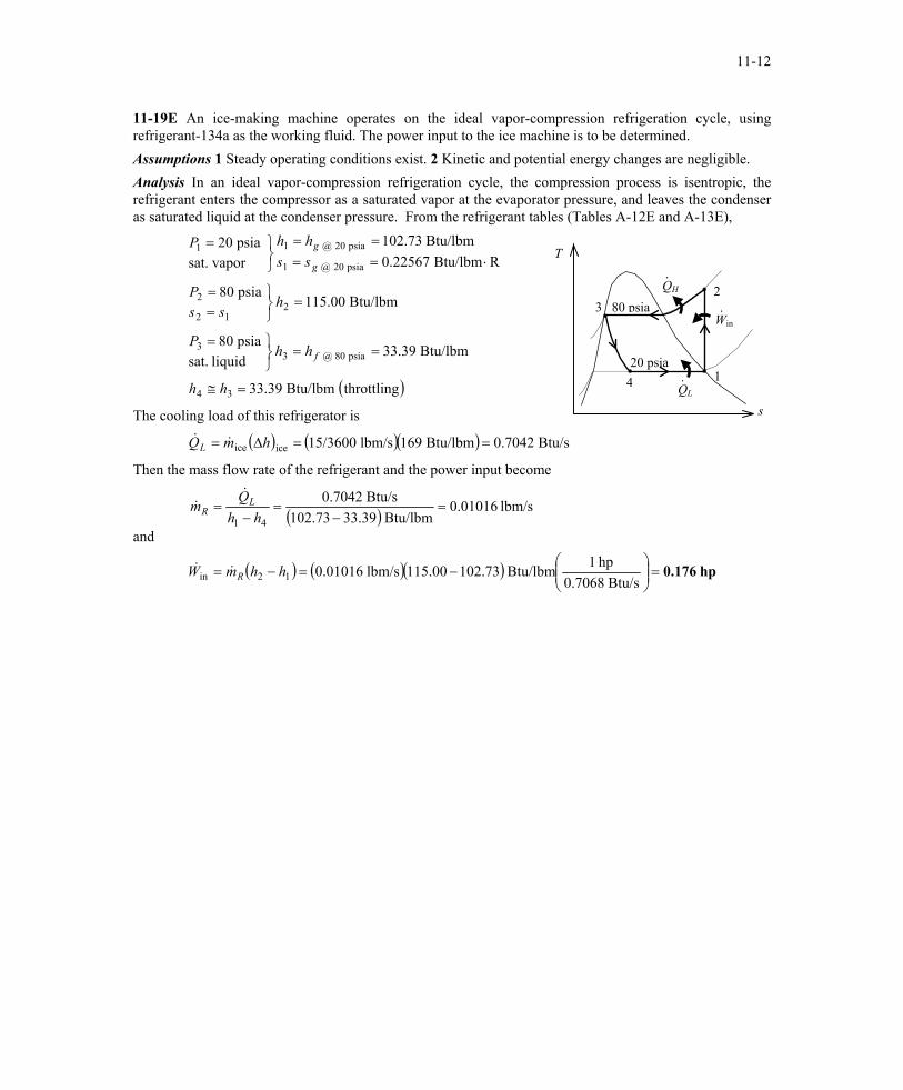
11-19E An ice-making machine operates on the ideal vapor-compression refrigeration cycle, using refrigerant-134a as the working fluid. The power input to the ice machine is to be determined. Assumptions 1 Steady operating conditions exist. 2 Kinetic and potential energy changes are negligible. Analysis In an ideal vapor-compression refrigeration cycle, the compression process is isentropic, the refrigerant enters the compressor as a saturated vapor at the evaporator pressure, and leaves the condenser as saturated liquid at the condenser pressure. From the refrigerant tables (Tables A-12E and A-13E),
( )throttlingBtu/lbm 39.33
Btu/lbm 39.33liquid sat.
psia 80
Btu/lbm 00.115psia 80
RBtu/lbm 22567.0Btu/lbm 73.102
vapor sat.psia 20
34
psia 08 @ 33
212
2
psia 20 @ 1
psia 20 @ 11
=≅
===
=
==
⋅====
=
hh
hhP
hss
P
sshhP
f
g
g
T
QH
QL
·
Win·
·
80 psia
4
32
120 psia
sThe cooling load of this refrigerator is
( ) ( )( ) Btu/s 0.7042Btu/lbm 169lbm/s 15/3600iceice ==∆= hmQL &&
Then the mass flow rate of the refrigerant and the power input become
and ( )
( ) ( )( ) hp 0.176=
−=−=
=−
=−
=
Btu/s 0.7068hp 1Btu/lbm 102.73115.00lbm/s 0.01016
lbm/s 0.01016Btu/lbm 33.39102.73
Btu/s 0.7042
12in
41
hhmW
hhQm
R
LR
&&
&&
PROPRIETARY MATERIAL. © 2006 The McGraw-Hill Companies, Inc. Limited distribution permitted only to teachers and educators for course preparation. If you are a student using this Manual, you are using it without permission.
11-13
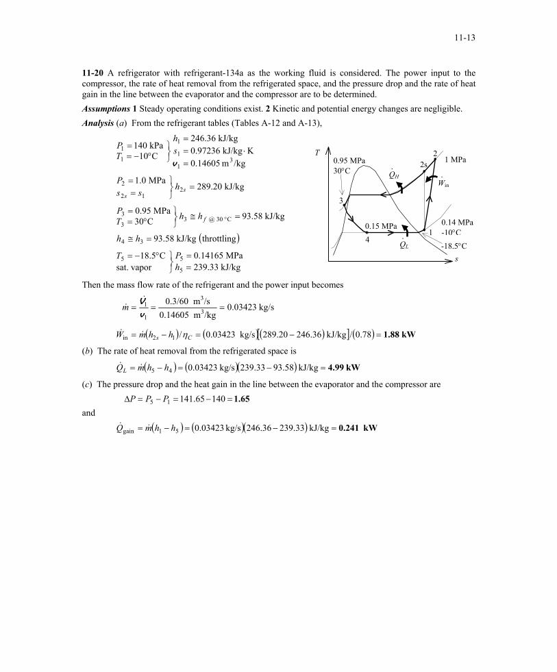
11-20 A refrigerator with refrigerant-134a as the working fluid is considered. The power input to the compressor, the rate of heat removal from the refrigerated space, and the pressure drop and the rate of heat gain in the line between the evaporator and the compressor are to be determined. Assumptions 1 Steady operating conditions exist. 2 Kinetic and potential energy changes are negligible. Analysis (a) From the refrigerant tables (Tables A-12 and A-13),
( )
kJ/kg 33.239MPa 14165.0
vapor sat.C5.18
throttlingkJ/kg 58.93
kJ/kg 58.93C30MPa 95.0
kJ/kg 20.289MPa 0.1
/kgm 14605.0KkJ/kg 97236.0
kJ/kg 36.246
C10kPa 140
5
55
34
C 30 @ 33
3
212
2
31
1
1
1
1
==
°−=
=≅
=≅
°==
=
==
=⋅=
=
°−==
°
hPT
hh
hhTP
hss
P
sh
TP
f
ss
vT
QH
QL -18.5°C
1 MPa
0.14 MPa-10°C
Win·
2
·
·
s
0.95 MPa30°C
4
3
2s
1 0.15 MPa
Then the mass flow rate of the refrigerant and the power input becomes
( ) ( ) ( )[ ] ( ) kW1.88 78.0/kJ/kg 246.36289.20kg/s 0.03423/
kg/s 0.03423/kgm 0.14605/sm 0.3/60
12in
3
3
1
1
=−=−=
===
Cs hhmW
m
η&&
&&
vV
(b) The rate of heat removal from the refrigerated space is
( ) ( )( ) kW 4.99=−=−= kJ/kg 93.58239.33kg/s 0.0342345 hhmQL &&
(c) The pressure drop and the heat gain in the line between the evaporator and the compressor are
and
( ) ( )( ) kW0.241
1.65
kJ/kg 239.33246.36kg/s 0.03423
14065.141
51gain
15
=−=−=
=−=−=∆
hhmQ
PPP
&&
PROPRIETARY MATERIAL. © 2006 The McGraw-Hill Companies, Inc. Limited distribution permitted only to teachers and educators for course preparation. If you are a student using this Manual, you are using it without permission.
11-14
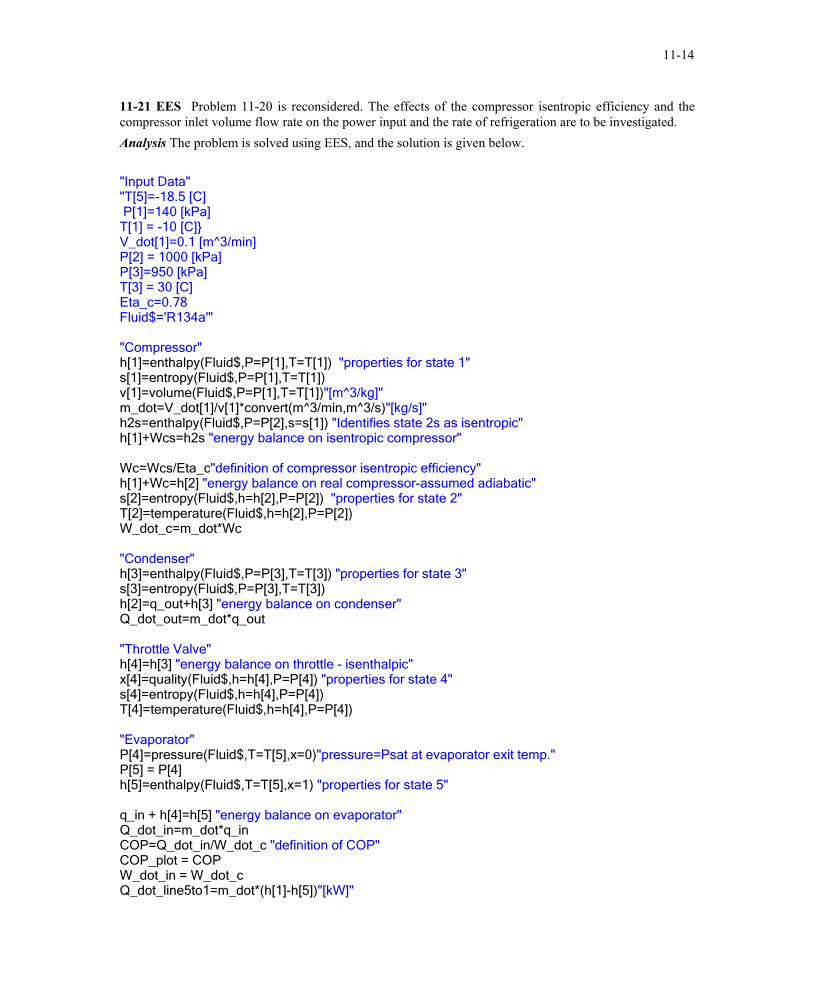
11-21 EES Problem 11-20 is reconsidered. The effects of the compressor isentropic efficiency and the compressor inlet volume flow rate on the power input and the rate of refrigeration are to be investigated. Analysis The problem is solved using EES, and the solution is given below. "Input Data" "T[5]=-18.5 [C] P[1]=140 [kPa] T[1] = -10 [C]} V_dot[1]=0.1 [m^3/min] P[2] = 1000 [kPa] P[3]=950 [kPa] T[3] = 30 [C] Eta_c=0.78 Fluid$='R134a'" "Compressor" h[1]=enthalpy(Fluid$,P=P[1],T=T[1]) "properties for state 1" s[1]=entropy(Fluid$,P=P[1],T=T[1]) v[1]=volume(Fluid$,P=P[1],T=T[1])"[m^3/kg]" m_dot=V_dot[1]/v[1]*convert(m^3/min,m^3/s)"[kg/s]" h2s=enthalpy(Fluid$,P=P[2],s=s[1]) "Identifies state 2s as isentropic" h[1]+Wcs=h2s "energy balance on isentropic compressor" Wc=Wcs/Eta_c"definition of compressor isentropic efficiency" h[1]+Wc=h[2] "energy balance on real compressor-assumed adiabatic" s[2]=entropy(Fluid$,h=h[2],P=P[2]) "properties for state 2" T[2]=temperature(Fluid$,h=h[2],P=P[2]) W_dot_c=m_dot*Wc "Condenser" h[3]=enthalpy(Fluid$,P=P[3],T=T[3]) "properties for state 3" s[3]=entropy(Fluid$,P=P[3],T=T[3]) h[2]=q_out+h[3] "energy balance on condenser" Q_dot_out=m_dot*q_out "Throttle Valve" h[4]=h[3] "energy balance on throttle - isenthalpic" x[4]=quality(Fluid$,h=h[4],P=P[4]) "properties for state 4" s[4]=entropy(Fluid$,h=h[4],P=P[4]) T[4]=temperature(Fluid$,h=h[4],P=P[4]) "Evaporator" P[4]=pressure(Fluid$,T=T[5],x=0)"pressure=Psat at evaporator exit temp." P[5] = P[4] h[5]=enthalpy(Fluid$,T=T[5],x=1) "properties for state 5" q_in + h[4]=h[5] "energy balance on evaporator" Q_dot_in=m_dot*q_in COP=Q_dot_in/W_dot_c "definition of COP" COP_plot = COP W_dot_in = W_dot_c Q_dot_line5to1=m_dot*(h[1]-h[5])"[kW]"
PROPRIETARY MATERIAL. © 2006 The McGraw-Hill Companies, Inc. Limited distribution permitted only to teachers and educators for course preparation. If you are a student using this Manual, you are using it without permission.
11-15
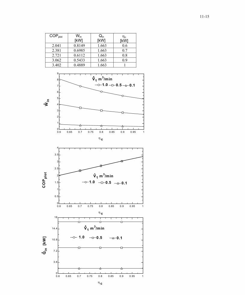
COPplot Win
[kW] Qin
[kW] ηc
[kW] 2.041 0.8149 1.663 0.6 2.381 0.6985 1.663 0.7 2.721 0.6112 1.663 0.8 3.062 0.5433 1.663 0.9 3.402 0.4889 1.663 1
0.6 0.65 0.7 0.75 0.8 0.85 0.9 0.95 10
1
2
3
4
5
6
7
8
9
η c
Win
V1 m3/min1.01.0 0.50.5 0.10.1
0.6 0.65 0.7 0.75 0.8 0.85 0.9 0.95 10
0.5
1
1.5
2
2.5
3
3.5
4
η c
CO
Ppl
ot V1 m3/min1.01.0 0.50.5 0.10.1
0.6 0.65 0.7 0.75 0.8 0.85 0.9 0.95 10
3.6
7.2
10.8
14.4
18
η c
Qin
[kW
] 1.0 1.0 0.50.5 0.10.1
V1 m3/min
PROPRIETARY MATERIAL. © 2006 The McGraw-Hill Companies, Inc. Limited distribution permitted only to teachers and educators for course preparation. If you are a student using this Manual, you are using it without permission.
11-16
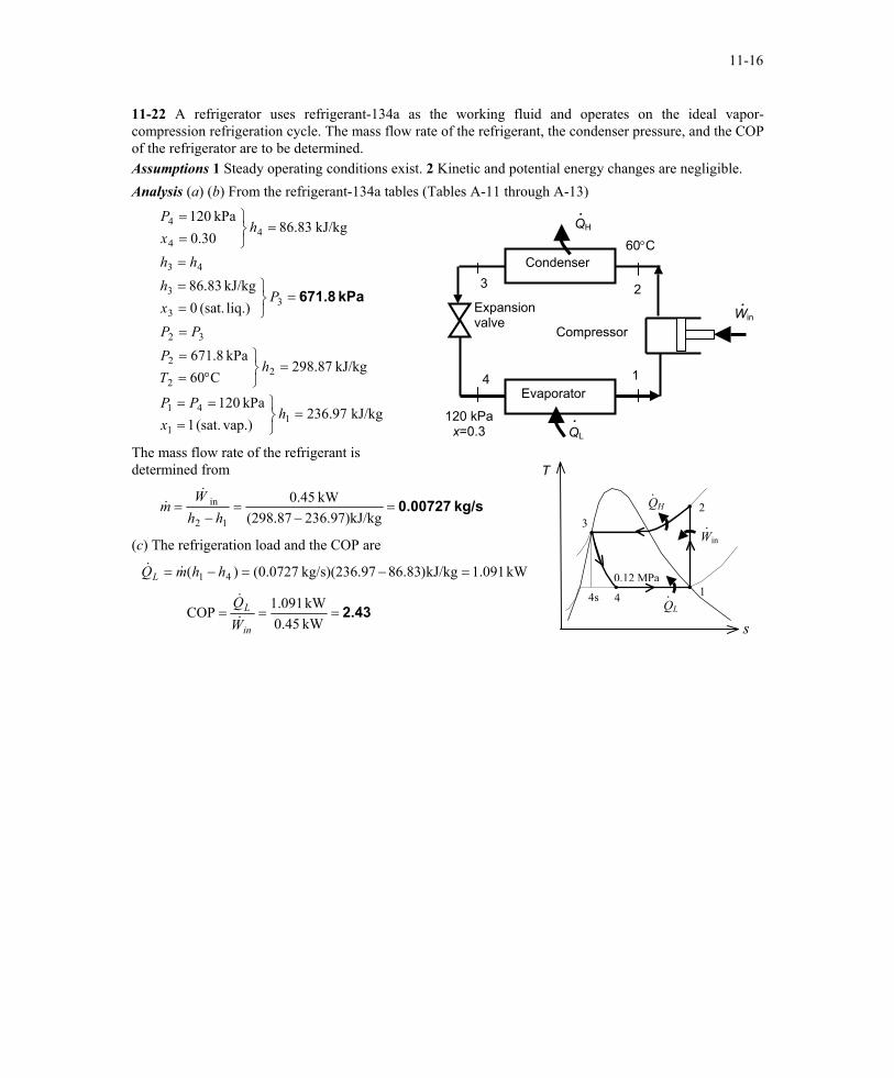
11-22 A refrigerator uses refrigerant-134a as the working fluid and operates on the ideal vapor-compression refrigeration cycle. The mass flow rate of the refrigerant, the condenser pressure, and the COP of the refrigerator are to be determined. Assumptions 1 Steady operating conditions exist. 2 Kinetic and potential energy changes are negligible. Analysis (a) (b) From the refrigerant-134a tables (Tables A-11 through A-13)
4
3 2
1
Win .
120 kPa x=0.3
Expansion valve
Compressor
Evaporator
Condenser 60°C
QH
.
.QL
kJ/kg 97.236 vap.)(sat. 1
kPa 120
kJ/kg 87.298C60
kPa 8.671
liq.) (sat. 0kJ/kg 83.86
kJ/kg 83.8630.0
kPa 120
11
41
22
2
32
33
3
43
44
4
=
===
=
°==
=
=
==
=
=
==
hx
PP
hTP
PP
Pxh
hh
hxP
kPa 671.8
The mass flow rate of the refrigerant is determined from T
QH
QL 4s
·
Win ·
·4
32
1 0.12 MPa
kg/s 0.00727=−
=−
=kg236.97)kJ/(298.87
kW 45.0
12
in
hhW
m&
&
(c) The refrigeration load and the COP are
Q kW 091.1kJ/kg)83.8697kg/s)(236. 0727.0()( 41 =−=−= hhmL &&
2.43===kW 0.45kW 091.1COP
in
L
WQ&
&
s
PROPRIETARY MATERIAL. © 2006 The McGraw-Hill Companies, Inc. Limited distribution permitted only to teachers and educators for course preparation. If you are a student using this Manual, you are using it without permission.
11-17
Selecting the Right Refrigerant 11-23C The desirable characteristics of a refrigerant are to have an evaporator pressure which is above the atmospheric pressure, and a condenser pressure which corresponds to a saturation temperature above the temperature of the cooling medium. Other desirable characteristics of a refrigerant include being nontoxic, noncorrosive, nonflammable, chemically stable, having a high enthalpy of vaporization (minimizes the mass flow rate) and, of course, being available at low cost. 11-24C The minimum pressure that the refrigerant needs to be compressed to is the saturation pressure of the refrigerant at 30°C, which is 0.771 MPa. At lower pressures, the refrigerant will have to condense at temperatures lower than the temperature of the surroundings, which cannot happen. 11-25C Allowing a temperature difference of 10°C for effective heat transfer, the evaporation temperature of the refrigerant should be -20°C. The saturation pressure corresponding to -20°C is 0.133 MPa. Therefore, the recommended pressure would be 0.12 MPa. 11-26 A refrigerator that operates on the ideal vapor-compression cycle with refrigerant-134a is considered. Reasonable pressures for the evaporator and the condenser are to be selected. Assumptions 1 Steady operating conditions exist. 2 Kinetic and potential energy changes are negligible. Analysis Allowing a temperature difference of 10°C for effective heat transfer, the evaporation and condensation temperatures of the refrigerant should be -20°C and 35°C, respectively. The saturation pressures corresponding to these temperatures are 0.133 MPa and 0.888 MPa. Therefore, the recommended evaporator and condenser pressures are 0.133 MPa and 0.888 MPa, respectively. 11-27 A heat pump that operates on the ideal vapor-compression cycle with refrigerant-134a is considered. Reasonable pressures for the evaporator and the condenser are to be selected. Assumptions 1 Steady operating conditions exist. 2 Kinetic and potential energy changes are negligible. Analysis Allowing a temperature difference of 10°C for effective heat transfer, the evaporation and condensation temperatures of the refrigerant should be 0°C and 32°C, respectively. The saturation pressures corresponding to these temperatures are 0.293 MPa and 0.816 MPa. Therefore, the recommended evaporator and condenser pressures are 0.293 MPa and 0.816 MPa, respectively. Heat Pump Systems 11-28C A heat pump system is more cost effective in Miami because of the low heating loads and high cooling loads at that location. 11-29C A water-source heat pump extracts heat from water instead of air. Water-source heat pumps have higher COPs than the air-source systems because the temperature of water is higher than the temperature of air in winter.
PROPRIETARY MATERIAL. © 2006 The McGraw-Hill Companies, Inc. Limited distribution permitted only to teachers and educators for course preparation. If you are a student using this Manual, you are using it without permission.

11-18
11-30E A heat pump that operates on the ideal vapor-compression cycle with refrigerant-134a is considered. The power input to the heat pump and the electric power saved by using a heat pump instead of a resistance heater are to be determined. Assumptions 1 Steady operating conditions exist. 2 Kinetic and potential energy changes are negligible. Analysis In an ideal vapor-compression refrigeration cycle, the compression process is isentropic, the refrigerant enters the compressor as a saturated vapor at the evaporator pressure, and leaves the condenser as saturated liquid at the condenser pressure. From the refrigerant tables (Tables A-12E and A-13E),
( )throttlingBtu/lbm 79.41
Btu/lbm 79.41liquid sat.
psia 120
Btu/lbm 62.116psia 120
RBtu/lbm 22188.0Btu/lbm 81.108
vapor sat.psia 50
34
psia 120 @ 33
212
2
psia 50 @ 1
psia 50 @ 11
=≅
===
=
==
⋅====
=
hh
hhP
hss
P
sshhP
f
g
g
QH
QL
House ·
Win·
·
120 psia
4
32
1 50 psia
T
The mass flow rate of the refrigerant and the power input to the compressor are determined from s
and ( )
( ) ( )( )Btu/s 0.7068 = hp 1 sinceBtu/s .7381
Btu/lbm 108.81116.62kg/s 0.2227
lbm/s 0.2227Btu/lbm 41.79116.62Btu/s 060,000/360
12in
32
hp 2.46==−=−=
=−
=−
==
hhmW
hhQ
m H
H
H
&&
&&&
The electrical power required without the heat pump is
Thus,
( )
kW 0.7457 = hp 1 sincekW 75.1546.258.23
hp .5823Btu/s 0.7068
hp 1Btu/s 060,000/360
insaved
==−=−=
=
==
hp 21.1WWW
QW
e
He
&&&
&&
PROPRIETARY MATERIAL. © 2006 The McGraw-Hill Companies, Inc. Limited distribution permitted only to teachers and educators for course preparation. If you are a student using this Manual, you are using it without permission.
11-19
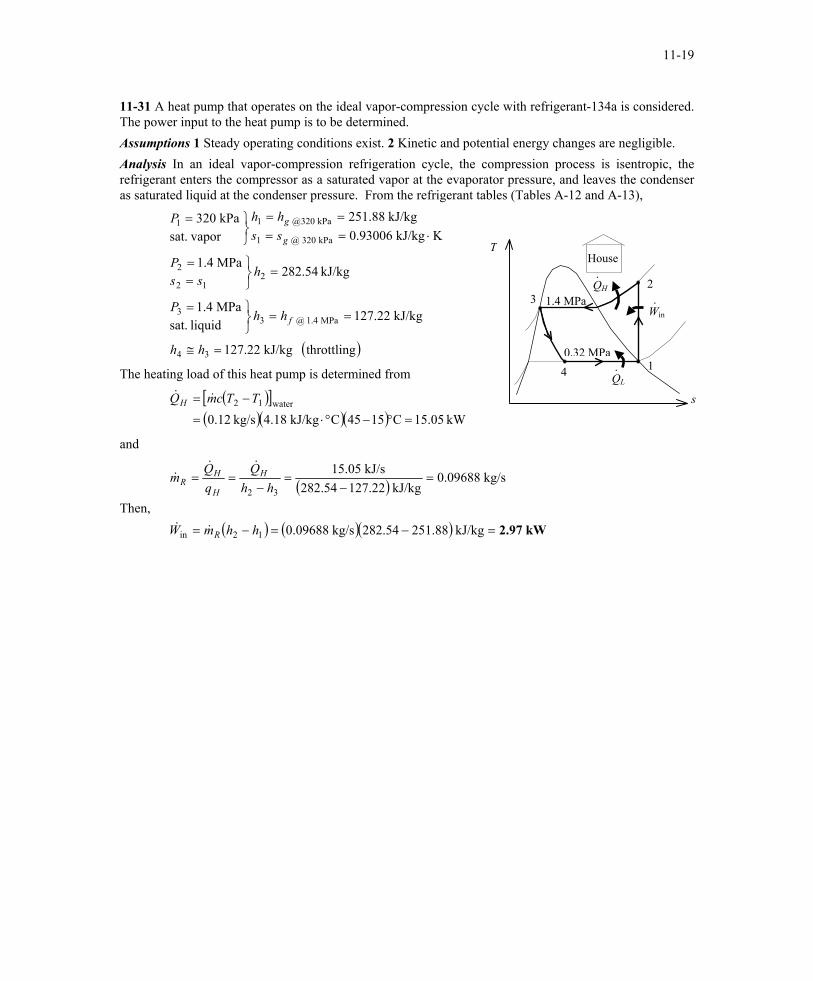
11-31 A heat pump that operates on the ideal vapor-compression cycle with refrigerant-134a is considered. The power input to the heat pump is to be determined. Assumptions 1 Steady operating conditions exist. 2 Kinetic and potential energy changes are negligible. Analysis In an ideal vapor-compression refrigeration cycle, the compression process is isentropic, the refrigerant enters the compressor as a saturated vapor at the evaporator pressure, and leaves the condenser as saturated liquid at the condenser pressure. From the refrigerant tables (Tables A-12 and A-13),
( )throttling kJ/kg 22.127
kJ/kg 22.127liquid sat.
MPa 4.1
kJ/kg 54.282MPa 4.1
KkJ/kg 93006.0kJ/kg 88.251
vapor sat.kPa 320
34
MPa 4.1 @ 33
212
2
kPa 320 @ 1
kPa 320@ 11
=≅
===
=
==
⋅====
=
hh
hhP
hss
P
sshhP
f
g
g
QH
QL
House ·
Win·
·
1.4 MPa
4
32
1 0.32 MPa
T
The heating load of this heat pump is determined from
( )[ ]
( )( )( ) kW .0515C1545CkJ/kg 4.18kg/s 0.12water12
=°−°⋅=
−= TTcmQH && s
and
Then, ( )
( ) ( )( ) kW 2.97=−=−=
=−
=−
==
kJ/kg 251.88282.54kg/s 0.09688
kg/s 0.09688kJ/kg 127.22282.54
kJ/s 15.05
12in
32
hhmW
hhQ
m
R
H
H
HR
&&
&&&
PROPRIETARY MATERIAL. © 2006 The McGraw-Hill Companies, Inc. Limited distribution permitted only to teachers and educators for course preparation. If you are a student using this Manual, you are using it without permission.
11-20
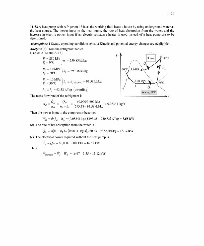
11-32 A heat pump with refrigerant-134a as the working fluid heats a house by using underground water as the heat source. The power input to the heat pump, the rate of heat absorption from the water, and the increase in electric power input if an electric resistance heater is used instead of a heat pump are to be determined. Assumptions 1 Steady operating conditions exist. 2 Kinetic and potential energy changes are negligible. Analysis (a) From the refrigerant tables (Tables A-12 and A-13),
QH
QL
1 MPa
Water, 8°C
60°CHouse
0°C
Win ·
2
·
·
s
4
330°C
1 0.28 MPa
T
( )throttling kJ/kg 58.93
kJ/kg 58.93C30MPa 0.1
kJ/kg 38.293C60MPa 0.1
kJ/kg 83.250C0kPa 280
34
C30 @ 33
3
22
2
11
1
=≅
=≅
°==
=
°==
=
°==
°
hh
hhTP
hTP
hTP
f
The mass flow rate of the refrigerant is
( ) kg/s 0.08341kJ/kg 93.58293.38
kJ/s 0060,000/3,6
32=
−=
−==
hhQ
qQm H
H
HR
&&&
Then the power input to the compressor becomes
( ) ( )( ) kW 3.55=−=−= kJ/kg 250.83293.38kg/s 0.0834112in hhmW &&
(b) The rate of hat absorption from the water is
( ) ( )( ) kW 13.12=−=−= kJ/kg 93.58250.83kg/s 0.0834141 hhmQL &&
(c) The electrical power required without the heat pump is
Thus,
kW 13.12=−=−=
===
55.367.16
kW 16.67kJ/s 3600/000,60
inincrease WWW
QW
e
He
&&&
&&
PROPRIETARY MATERIAL. © 2006 The McGraw-Hill Companies, Inc. Limited distribution permitted only to teachers and educators for course preparation. If you are a student using this Manual, you are using it without permission.
11-21
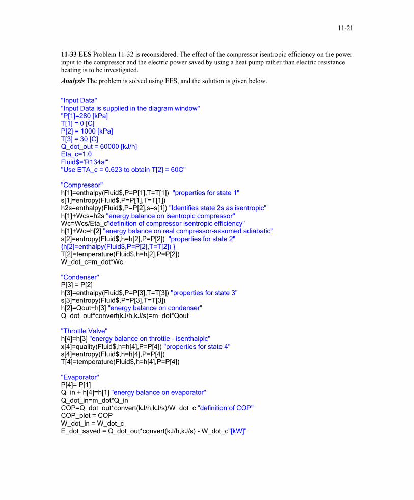
11-33 EES Problem 11-32 is reconsidered. The effect of the compressor isentropic efficiency on the power input to the compressor and the electric power saved by using a heat pump rather than electric resistance heating is to be investigated. Analysis The problem is solved using EES, and the solution is given below. "Input Data" "Input Data is supplied in the diagram window" "P[1]=280 [kPa] T[1] = 0 [C] P[2] = 1000 [kPa] T[3] = 30 [C] Q_dot_out = 60000 [kJ/h] Eta_c=1.0 Fluid$='R134a'" "Use ETA_c = 0.623 to obtain T[2] = 60C" "Compressor" h[1]=enthalpy(Fluid$,P=P[1],T=T[1]) "properties for state 1" s[1]=entropy(Fluid$,P=P[1],T=T[1]) h2s=enthalpy(Fluid$,P=P[2],s=s[1]) "Identifies state 2s as isentropic" h[1]+Wcs=h2s "energy balance on isentropic compressor" Wc=Wcs/Eta_c"definition of compressor isentropic efficiency" h[1]+Wc=h[2] "energy balance on real compressor-assumed adiabatic" s[2]=entropy(Fluid$,h=h[2],P=P[2]) "properties for state 2" {h[2]=enthalpy(Fluid$,P=P[2],T=T[2]) } T[2]=temperature(Fluid$,h=h[2],P=P[2]) W_dot_c=m_dot*Wc "Condenser" P[3] = P[2] h[3]=enthalpy(Fluid$,P=P[3],T=T[3]) "properties for state 3" s[3]=entropy(Fluid$,P=P[3],T=T[3]) h[2]=Qout+h[3] "energy balance on condenser" Q_dot_out*convert(kJ/h,kJ/s)=m_dot*Qout "Throttle Valve" h[4]=h[3] "energy balance on throttle - isenthalpic" x[4]=quality(Fluid$,h=h[4],P=P[4]) "properties for state 4" s[4]=entropy(Fluid$,h=h[4],P=P[4]) T[4]=temperature(Fluid$,h=h[4],P=P[4]) "Evaporator" P[4]= P[1] Q_in + h[4]=h[1] "energy balance on evaporator" Q_dot_in=m_dot*Q_in COP=Q_dot_out*convert(kJ/h,kJ/s)/W_dot_c "definition of COP" COP_plot = COP W_dot_in = W_dot_c E_dot_saved = Q_dot_out*convert(kJ/h,kJ/s) - W_dot_c"[kW]"
PROPRIETARY MATERIAL. © 2006 The McGraw-Hill Companies, Inc. Limited distribution permitted only to teachers and educators for course preparation. If you are a student using this Manual, you are using it without permission.
11-22
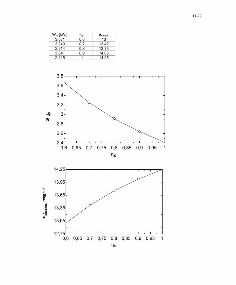
Win [kW] ηc Esaved
3.671 0.6 13 3.249 0.7 13.42 2.914 0.8 13.75 2.641 0.9 14.03 2.415 1 14.25
0,6 0,65 0,7 0,75 0,8 0,85 0,9 0,95 12,4
2,6
2,8
3
3,2
3,4
3,6
3,8
ηc
Win
0,6 0,65 0,7 0,75 0,8 0,85 0,9 0,95 112,75
13,05
13,35
13,65
13,95
14,25
ηc
Esaved
[kW]
PROPRIETARY MATERIAL. © 2006 The McGraw-Hill Companies, Inc. Limited distribution permitted only to teachers and educators for course preparation. If you are a student using this Manual, you are using it without permission.
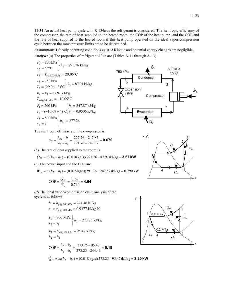
11-23
11-34 An actual heat pump cycle with R-134a as the refrigerant is considered. The isentropic efficiency of the compressor, the rate of heat supplied to the heated room, the COP of the heat pump, and the COP and the rate of heat supplied to the heated room if this heat pump operated on the ideal vapor-compression cycle between the same pressure limits are to be determined. Assumptions 1 Steady operating conditions exist. 2 Kinetic and potential energy changes are negligible. Analysis (a) The properties of refrigerant-134a are (Tables A-11 through A-13)
26.277kPa 800
kJ/kg 9506.0kJ/kg 87.247
C)409.10(kPa 200
C09.10kJ/kg 91.87
kJ/kg 91.87C)306.29(
kPa 750
C06.29
kJ/kg 76.291C55kPa 800
212
2
1
1
1
1
kPa sat@200
34
33
3
kPa sat@7503
22
2
=
==
==
°+−==
°−===
=
°−==
°==
=
°==
shss
P
sh
TP
Thh
hTP
TT
hTP
4
3 2
1
Win .
800 kPa 55°C
Expansion valve
Compressor
Evaporator
Condenser
750 kPa QH.
.QL
The isentropic efficiency of the compressor is T
QH
QL
Win·
2
·
·
4
3
2
1
0.670=−−
=−−
=87.24776.29187.24726.277
12
12
hhhh s
Cη
(b) The rate of heat supplied to the room is
Q kW 3.67=−=−= kJ/kg)91.8776kg/s)(291. 018.0()( 32 hhmH &&
(c) The power input and the COP are
W kW 790.0kJ/kg)87.24776kg/s)(291. 018.0()( 12in =−=−= hhm&&
s 4.64===
790.067.3COP
inWQH&
&
(d) The ideal vapor-compression cycle analysis of the cycle is as follows: T
QH
QL 4s
·
Win ·
·
0.8 MPa
4
32
1 0.2 MPa
kJ/kg.K 9377.0kJ/kg 46.244
kPa 200 @1
kPa 200 @1
====
g
g
sshh
kJ/kg 25.273MPa 800
212
2 =
==
hss
P
34
kPa 800 @3 kJ/kg 47.95hhhh f
===
s 6.18=
−−
=−−
=46.24425.273
47.9525.273COP12
32
hhhh
kW 3.20=−=−= kJ/kg)47.9525kg/s)(273. 018.0()( 32 hhmQH &&
PROPRIETARY MATERIAL. © 2006 The McGraw-Hill Companies, Inc. Limited distribution permitted only to teachers and educators for course preparation. If you are a student using this Manual, you are using it without permission.
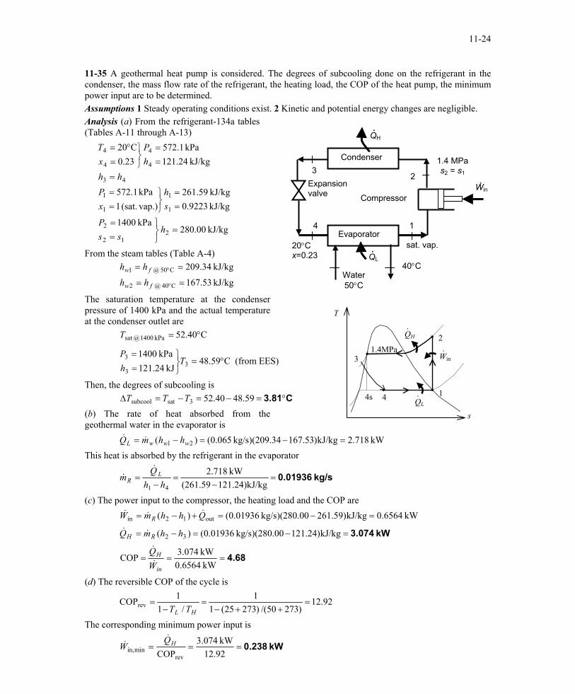
11-24
11-35 A geothermal heat pump is considered. The degrees of subcooling done on the refrigerant in the condenser, the mass flow rate of the refrigerant, the heating load, the COP of the heat pump, the minimum power input are to be determined. Assumptions 1 Steady operating conditions exist. 2 Kinetic and potential energy changes are negligible. Analysis (a) From the refrigerant-134a tables (Tables A-11 through A-13)
40°C Water50°C
Win .
sat. vap.
Expansion valve Compressor
Evaporator
Condenser
20°C x=0.23
QH.
4
32
1
1.4 MPa s2 = s1
.QL
kJ/kg 00.280kPa 1400
kJ/kg 9223.0kJ/kg 59.261
vap.)(sat. 1kPa 1.572
kJ/kg 24.121kPa 1.572
23.0C20
212
2
1
1
1
1
43
4
4
4
4
=
==
==
==
=
==
=°=
hss
P
sh
xP
hhhP
xT
From the steam tables (Table A-4)
kJ/kg 53.167
kJ/kg 34.209
C40 @ 2
C50 @ 1
==
==
°
°
fw
fw
hh
hh
The saturation temperature at the condenser pressure of 1400 kPa and the actual temperature at the condenser outlet are
T
QH
QL 4s
·
Win ·
·
1.4MPa
4
3
2
1
C40.52kPa 1400 @sat °=T
C59.48kJ 24.121
kPa 14003
3
3 °=
==
ThP
(from EES)
Then, the degrees of subcooling is C3.81°=−=−=∆ 59.4840.523satsubcool TTT (b) The rate of heat absorbed from the geothermal water in the evaporator is
s
kW 718.2kJ/kg)53.16734kg/s)(209. 065.0()( 21 =−=−= wwwL hhmQ && This heat is absorbed by the refrigerant in the evaporator
kg/s 0.01936=−
=−
=)kJ/kg24.121(261.59
kW 718.2
41 hhQ
m LR
&&
(c) The power input to the compressor, the heating load and the COP are kW 6564.0kJ/kg)59.26100kg/s)(280. 01936.0()( out12in =−=+−= QhhmW R
&&&
kW 3.074=−=−= kJ/kg)24.12100kg/s)(280. 01936.0()( 32 hhmQ RH &&
4.68===kW 0.6564
kW 074.3COPin
H
WQ&
&
(d) The reversible COP of the cycle is
92.12)27350/()27325(1
1/1
1COPrev =++−
=−
=HL TT
The corresponding minimum power input is
kW 0.238===92.12kW 074.3
COPrevminin,
HQW
&&
PROPRIETARY MATERIAL. © 2006 The McGraw-Hill Companies, Inc. Limited distribution permitted only to teachers and educators for course preparation. If you are a student using this Manual, you are using it without permission.
11-25
Innovative Refrigeration Systems 11-36C Performing the refrigeration in stages is called cascade refrigeration. In cascade refrigeration, two or more refrigeration cycles operate in series. Cascade refrigerators are more complex and expensive, but they have higher COP's, they can incorporate two or more different refrigerants, and they can achieve much lower temperatures. 11-37C Cascade refrigeration systems have higher COPs than the ordinary refrigeration systems operating between the same pressure limits. 11-38C The saturation pressure of refrigerant-134a at -32°C is 77 kPa, which is below the atmospheric pressure. In reality a pressure below this value should be used. Therefore, a cascade refrigeration system with a different refrigerant at the bottoming cycle is recommended in this case. 11-39C We would favor the two-stage compression refrigeration system with a flash chamber since it is simpler, cheaper, and has better heat transfer characteristics. 11-40C Yes, by expanding the refrigerant in stages in several throttling devices. 11-41C To take advantage of the cooling effect by throttling from high pressures to low pressures.
PROPRIETARY MATERIAL. © 2006 The McGraw-Hill Companies, Inc. Limited distribution permitted only to teachers and educators for course preparation. If you are a student using this Manual, you are using it without permission.
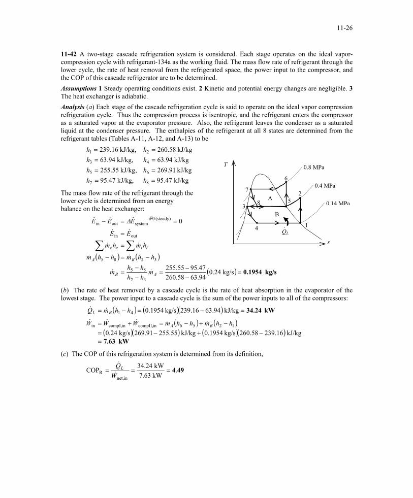
11-26
11-42 A two-stage cascade refrigeration system is considered. Each stage operates on the ideal vapor-compression cycle with refrigerant-134a as the working fluid. The mass flow rate of refrigerant through the lower cycle, the rate of heat removal from the refrigerated space, the power input to the compressor, and the COP of this cascade refrigerator are to be determined. Assumptions 1 Steady operating conditions exist. 2 Kinetic and potential energy changes are negligible. 3 The heat exchanger is adiabatic. Analysis (a) Each stage of the cascade refrigeration cycle is said to operate on the ideal vapor compression refrigeration cycle. Thus the compression process is isentropic, and the refrigerant enters the compressor as a saturated vapor at the evaporator pressure. Also, the refrigerant leaves the condenser as a saturated liquid at the condenser pressure. The enthalpies of the refrigerant at all 8 states are determined from the refrigerant tables (Tables A-11, A-12, and A-13) to be
kJ/kg 47.95kJ/kg 91.269
kJ/kg 94.63kJ/kg 58.260
kJ/kg, 47.95,kJ/kg 55.255
,kJ/kg 94.63,kJ/kg 16.239
8
6
4
2
7
5
3
1
====
====
hhhh
hhhh
T
The mass flow rate of the refrigerant through the lower cycle is determined from an energy balance on the heat exchanger:
( ) ( )
( ) kg/s 0.1954=−−
=−−
=
−=−
=
=
==−
∑∑
kg/s 0.2494.6358.26047.9555.255
0
32
85
3285
outin
(steady) 0systemoutin
AB
BA
iiee
mhhhh
m
hhmhhm
hmhm
EE
EEE
&&
&&
&&
&&
&&& ∆
3
QL
B
A 5 8
0.8 MPa
6
·
0.4 MPa
4
7 2
1
0.14 MPa
s
(b) The rate of heat removed by a cascade cycle is the rate of heat absorption in the evaporator of the lowest stage. The power input to a cascade cycle is the sum of the power inputs to all of the compressors:
( ) ( )( )( ) ( )
( )( ) ( )( )kW 7.63
kW 34.24
=−+−=
−+−=+=
=−=−=
kJ/kg 239.16260.58kg/s 0.1954kJ/kg 255.55269.91kg/s 0.24
kJ/kg 63.94239.16kg/s 0.1954
1256incompII,incompI,in
41
hhmhhmWWW
hhmQ
BA
BL
&&&&&
&&
(c) The COP of this refrigeration system is determined from its definition,
494.kW 7.63kW 34.24COP
innet,R ===
WQL&
&
PROPRIETARY MATERIAL. © 2006 The McGraw-Hill Companies, Inc. Limited distribution permitted only to teachers and educators for course preparation. If you are a student using this Manual, you are using it without permission.
11-27
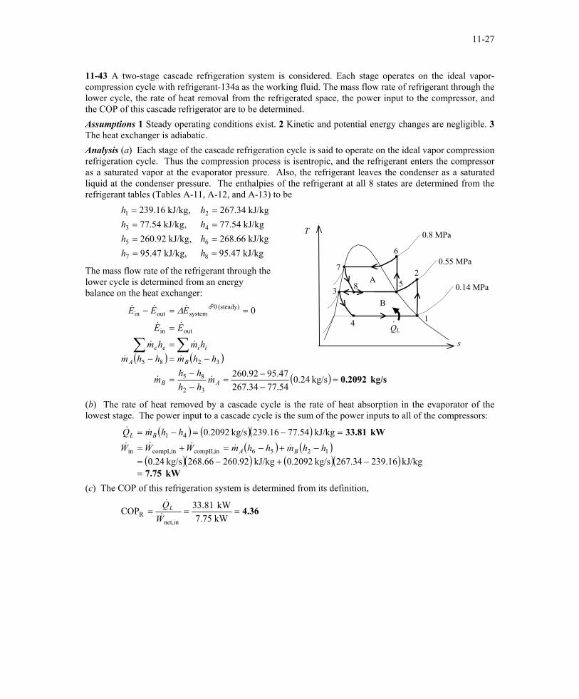
11-43 A two-stage cascade refrigeration system is considered. Each stage operates on the ideal vapor-compression cycle with refrigerant-134a as the working fluid. The mass flow rate of refrigerant through the lower cycle, the rate of heat removal from the refrigerated space, the power input to the compressor, and the COP of this cascade refrigerator are to be determined. Assumptions 1 Steady operating conditions exist. 2 Kinetic and potential energy changes are negligible. 3 The heat exchanger is adiabatic. Analysis (a) Each stage of the cascade refrigeration cycle is said to operate on the ideal vapor compression refrigeration cycle. Thus the compression process is isentropic, and the refrigerant enters the compressor as a saturated vapor at the evaporator pressure. Also, the refrigerant leaves the condenser as a saturated liquid at the condenser pressure. The enthalpies of the refrigerant at all 8 states are determined from the refrigerant tables (Tables A-11, A-12, and A-13) to be
kJ/kg 47.95kJ/kg 66.268
kJ/kg 54.77kJ/kg 34.267
kJ/kg, 47.95,kJ/kg 92.260
,kJ/kg 54.77,kJ/kg 16.239
8
6
4
2
7
5
3
1
====
====
hhhh
hhhh
T
The mass flow rate of the refrigerant through the lower cycle is determined from an energy balance on the heat exchanger:
( ) ( )
( ) kg/s 0.2092=−−
=−−
=
−=−=
=
==−
∑∑
kg/s 24.054.7734.26747.9592.260
0
32
85
3285
outin
(steady) 0systemoutin
AB
BA
iiee
mhhhh
m
hhmhhmhmhm
EE
EEE
&&
&&
&&
&&
&&& ∆
QL
3B
A 58
0.8 MPa
6
·
0.55 MPa
4
7 2
1
0.14 MPa
s
(b) The rate of heat removed by a cascade cycle is the rate of heat absorption in the evaporator of the lowest stage. The power input to a cascade cycle is the sum of the power inputs to all of the compressors:
( ) ( )( )( ) ( )
( )( ) ( )( )kW 7.75
kW 33.81
=−+−=
−+−=+=
=−=−=
kJ/kg 16.23934.267kg/s 2092.0kJ/kg 92.26066.268kg/s 24.0
kJ/kg 54.7716.239kg/s 2092.0
1256incompII,compI,inin
41
hhmhhmWWW
hhmQ
BA
BL
&&&&&
&&
(c) The COP of this refrigeration system is determined from its definition,
4.36===kW 75.7kW 81.33COP
innet,R W
QL&
&
PROPRIETARY MATERIAL. © 2006 The McGraw-Hill Companies, Inc. Limited distribution permitted only to teachers and educators for course preparation. If you are a student using this Manual, you are using it without permission.
11-28
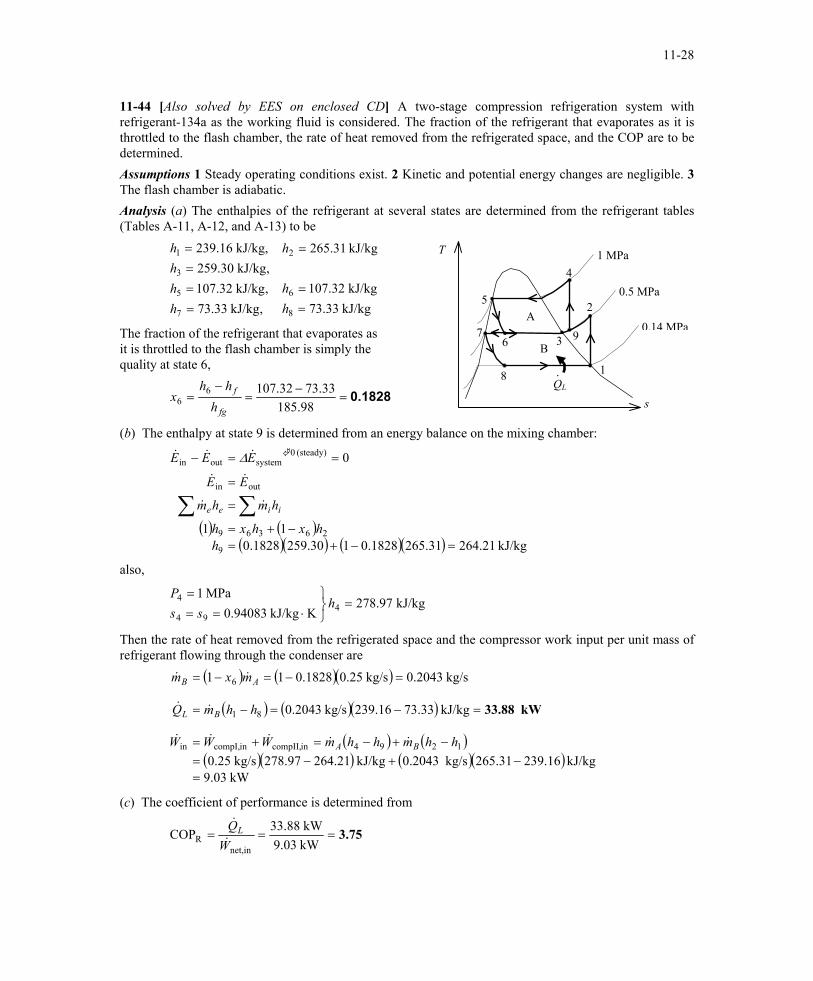
11-44 [Also solved by EES on enclosed CD] A two-stage compression refrigeration system with refrigerant-134a as the working fluid is considered. The fraction of the refrigerant that evaporates as it is throttled to the flash chamber, the rate of heat removed from the refrigerated space, and the COP are to be determined. Assumptions 1 Steady operating conditions exist. 2 Kinetic and potential energy changes are negligible. 3 The flash chamber is adiabatic. Analysis (a) The enthalpies of the refrigerant at several states are determined from the refrigerant tables (Tables A-11, A-12, and A-13) to be
kJ/kg 33.73kJ/kg 32.107
kJ/kg 31.265
,kJ/kg 33.73,kJ/kg 32.107,kJ/kg 30.259
kJ/kg, 16.239
8
6
2
7
5
3
1
==
=
====
hh
h
hhhh T
QL
73B
A9 6
1 MPa 4
·
0.5 MPa
8
5 2
1
0.14 MPaThe fraction of the refrigerant that evaporates as it is throttled to the flash chamber is simply the quality at state 6,
0.1828=−
=−
=98.185
33.7332.10766
fg
f
hhh
x s
(b) The enthalpy at state 9 is determined from an energy balance on the mixing chamber:
( ) ( )( )( ) ( )( ) kJ/kg 21.26431.2651828.0130.2591828.0
11
0
9
26369
outin
(steady) 0systemoutin
=−+=−+=
=
=
==−
∑∑h
hxhxh
hmhm
EE
EEE
iiee &&
&&
&&& ∆
also,
kJ/kg 97.278KkJ/kg 94083.0
MPa 14
94
4 =
⋅===
hss
P
Then the rate of heat removed from the refrigerated space and the compressor work input per unit mass of refrigerant flowing through the condenser are
( ) ( )( )
( ) ( )( )
( ) ( )( )( ) ( )( )
kW .039kJ/kg 239.16265.31kg/s 0.2043kJ/kg 264.21278.97kg/s 0.25
kJ/kg 73.33239.16kg/s 0.2043
kg/s 0.2043kg/s 0.251828.011
1294incompII,incompI,in
81
6
=−+−=
−+−=+=
=−=−=
=−=−=
hhmhhmWWW
hhmQ
mxm
BA
BL
AB
&&&&&
&&
&&
kW 33.88
(c) The coefficient of performance is determined from
3.75===kW 9.03kW 33.88COP
innet,R W
QL&
&
PROPRIETARY MATERIAL. © 2006 The McGraw-Hill Companies, Inc. Limited distribution permitted only to teachers and educators for course preparation. If you are a student using this Manual, you are using it without permission.
11-29
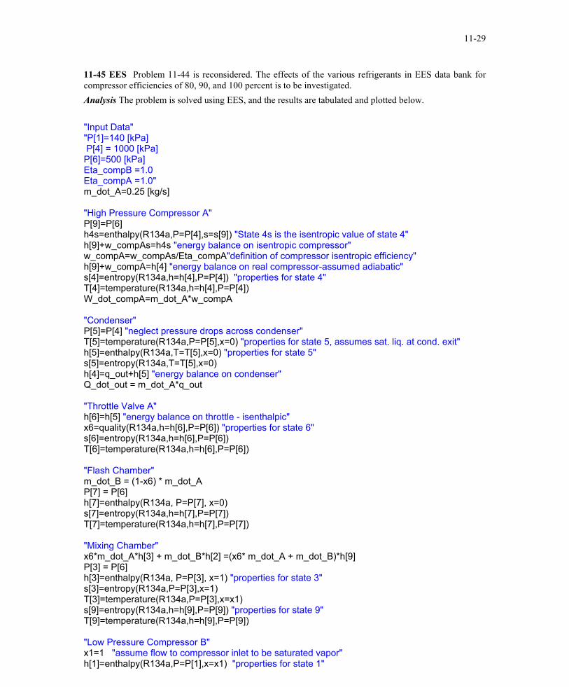
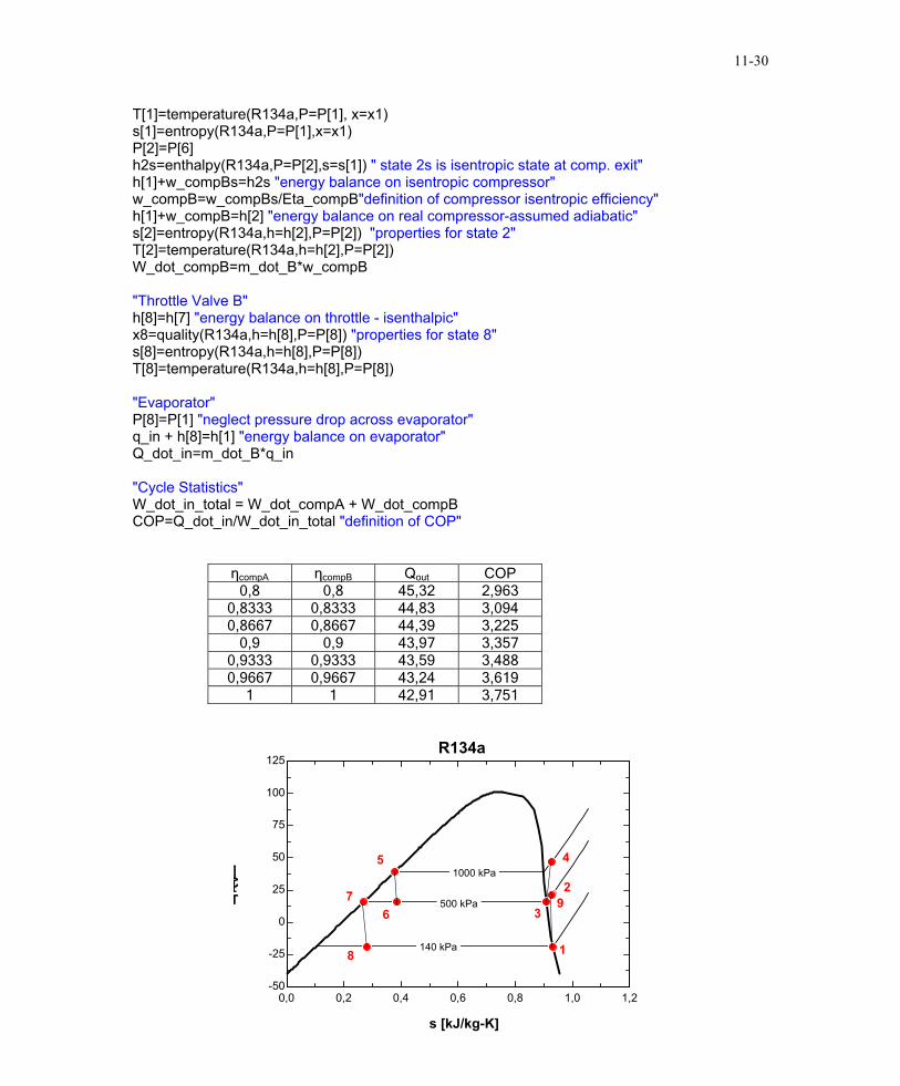
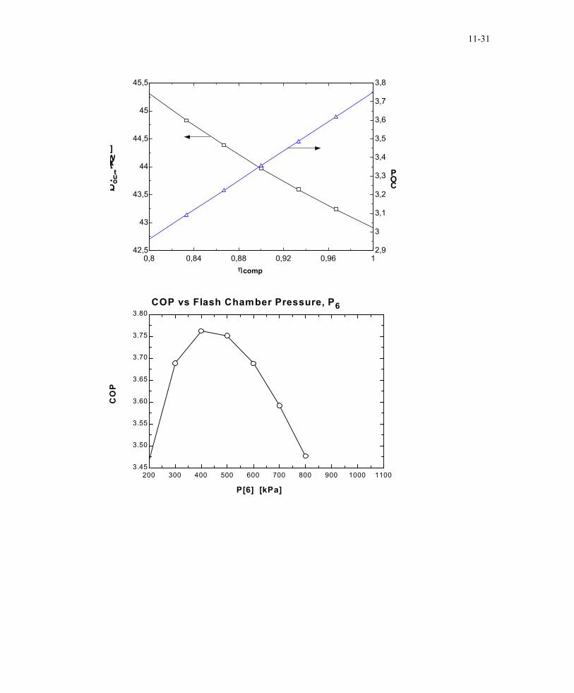
11-45 EES Problem 11-44 is reconsidered. The effects of the various refrigerants in EES data bank for compressor efficiencies of 80, 90, and 100 percent is to be investigated. Analysis The problem is solved using EES, and the results are tabulated and plotted below. "Input Data" "P[1]=140 [kPa] P[4] = 1000 [kPa] P[6]=500 [kPa] Eta_compB =1.0 Eta_compA =1.0" m_dot_A=0.25 [kg/s] "High Pressure Compressor A" P[9]=P[6] h4s=enthalpy(R134a,P=P[4],s=s[9]) "State 4s is the isentropic value of state 4" h[9]+w_compAs=h4s "energy balance on isentropic compressor" w_compA=w_compAs/Eta_compA"definition of compressor isentropic efficiency" h[9]+w_compA=h[4] "energy balance on real compressor-assumed adiabatic" s[4]=entropy(R134a,h=h[4],P=P[4]) "properties for state 4" T[4]=temperature(R134a,h=h[4],P=P[4]) W_dot_compA=m_dot_A*w_compA "Condenser" P[5]=P[4] "neglect pressure drops across condenser" T[5]=temperature(R134a,P=P[5],x=0) "properties for state 5, assumes sat. liq. at cond. exit" h[5]=enthalpy(R134a,T=T[5],x=0) "properties for state 5" s[5]=entropy(R134a,T=T[5],x=0) h[4]=q_out+h[5] "energy balance on condenser" Q_dot_out = m_dot_A*q_out "Throttle Valve A" h[6]=h[5] "energy balance on throttle - isenthalpic" x6=quality(R134a,h=h[6],P=P[6]) "properties for state 6" s[6]=entropy(R134a,h=h[6],P=P[6]) T[6]=temperature(R134a,h=h[6],P=P[6]) "Flash Chamber" m_dot_B = (1-x6) * m_dot_A P[7] = P[6] h[7]=enthalpy(R134a, P=P[7], x=0) s[7]=entropy(R134a,h=h[7],P=P[7]) T[7]=temperature(R134a,h=h[7],P=P[7]) "Mixing Chamber" x6*m_dot_A*h[3] + m_dot_B*h[2] =(x6* m_dot_A + m_dot_B)*h[9] P[3] = P[6] h[3]=enthalpy(R134a, P=P[3], x=1) "properties for state 3" s[3]=entropy(R134a,P=P[3],x=1) T[3]=temperature(R134a,P=P[3],x=x1) s[9]=entropy(R134a,h=h[9],P=P[9]) "properties for state 9" T[9]=temperature(R134a,h=h[9],P=P[9]) "Low Pressure Compressor B" x1=1 "assume flow to compressor inlet to be saturated vapor" h[1]=enthalpy(R134a,P=P[1],x=x1) "properties for state 1"
PROPRIETARY MATERIAL. © 2006 The McGraw-Hill Companies, Inc. Limited distribution permitted only to teachers and educators for course preparation. If you are a student using this Manual, you are using it without permission.
11-30
T[1]=temperature(R134a,P=P[1], x=x1) s[1]=entropy(R134a,P=P[1],x=x1) P[2]=P[6] h2s=enthalpy(R134a,P=P[2],s=s[1]) " state 2s is isentropic state at comp. exit" h[1]+w_compBs=h2s "energy balance on isentropic compressor" w_compB=w_compBs/Eta_compB"definition of compressor isentropic efficiency" h[1]+w_compB=h[2] "energy balance on real compressor-assumed adiabatic" s[2]=entropy(R134a,h=h[2],P=P[2]) "properties for state 2" T[2]=temperature(R134a,h=h[2],P=P[2]) W_dot_compB=m_dot_B*w_compB "Throttle Valve B" h[8]=h[7] "energy balance on throttle - isenthalpic" x8=quality(R134a,h=h[8],P=P[8]) "properties for state 8" s[8]=entropy(R134a,h=h[8],P=P[8]) T[8]=temperature(R134a,h=h[8],P=P[8]) "Evaporator" P[8]=P[1] "neglect pressure drop across evaporator" q_in + h[8]=h[1] "energy balance on evaporator" Q_dot_in=m_dot_B*q_in "Cycle Statistics" W_dot_in_total = W_dot_compA + W_dot_compB COP=Q_dot_in/W_dot_in_total "definition of COP"
ηcompA ηcompB Qout COP 0,8 0,8 45,32 2,963
0,8333 0,8333 44,83 3,094 0,8667 0,8667 44,39 3,225
0,9 0,9 43,97 3,357 0,9333 0,9333 43,59 3,488 0,9667 0,9667 43,24 3,619
1 1 42,91 3,751
0,0 0,2 0,4 0,6 0,8 1,0 1,2-50
-25
0
25
50
75
100
125
s [kJ/kg-K]
T[C] 1000 kPa
500 kPa
140 kPa
R134a
1
2
39
45
67
8
PROPRIETARY MATERIAL. © 2006 The McGraw-Hill Companies, Inc. Limited distribution permitted only to teachers and educators for course preparation. If you are a student using this Manual, you are using it without permission.
11-31
0,8 0,84 0,88 0,92 0,96 1
42,5
43
43,5
44
44,5
45
45,5
2,9
3
3,1
3,2
3,3
3,4
3,5
3,6
3,7
3,8
ηcomp
Qout
[kW]
COP
200 300 400 500 600 700 800 900 1000 11003.45
3.50
3.55
3.60
3.65
3.70
3.75
3.80
P[6] [kPa]
CO
P
COP vs Flash Chamber Pressure, P6
PROPRIETARY MATERIAL. © 2006 The McGraw-Hill Companies, Inc. Limited distribution permitted only to teachers and educators for course preparation. If you are a student using this Manual, you are using it without permission.
11-32
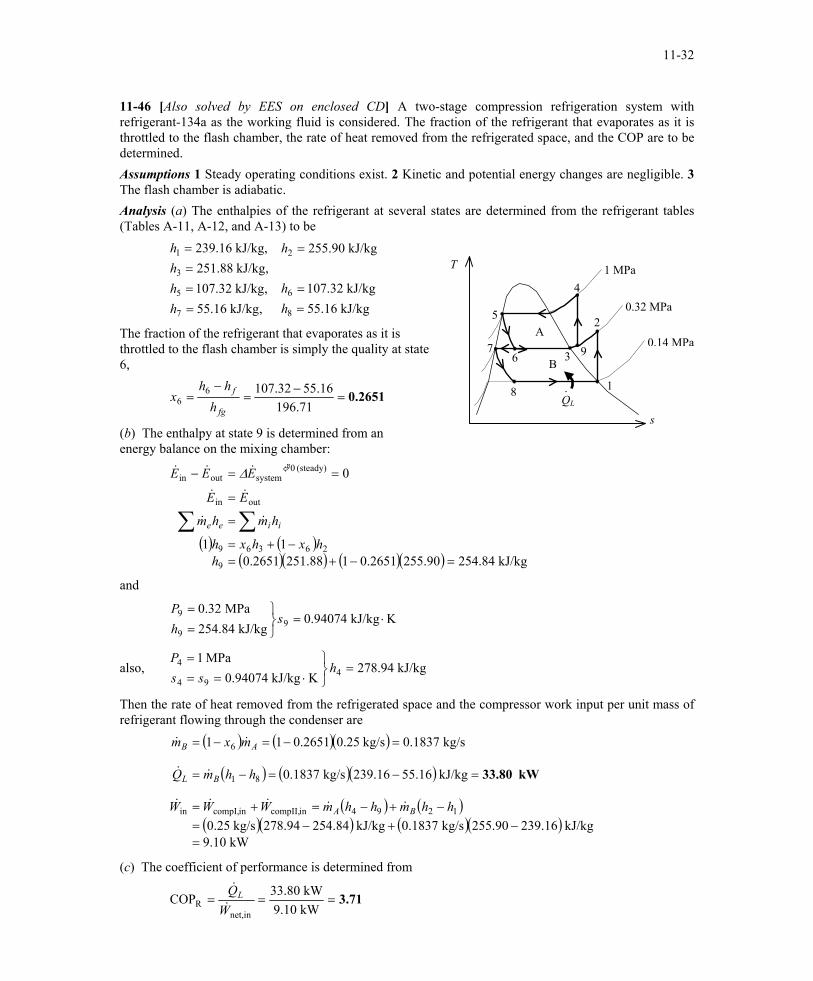
11-46 [Also solved by EES on enclosed CD] A two-stage compression refrigeration system with refrigerant-134a as the working fluid is considered. The fraction of the refrigerant that evaporates as it is throttled to the flash chamber, the rate of heat removed from the refrigerated space, and the COP are to be determined. Assumptions 1 Steady operating conditions exist. 2 Kinetic and potential energy changes are negligible. 3 The flash chamber is adiabatic. Analysis (a) The enthalpies of the refrigerant at several states are determined from the refrigerant tables (Tables A-11, A-12, and A-13) to be
kJ/kg 16.55kJ/kg 32.107
kJ/kg 90.255
,kJ/kg 16.55,kJ/kg 32.107,kJ/kg 88.251
kJ/kg, 16.239
8
6
2
7
5
3
1
==
=
====
hh
h
hhhh
T
QL
73 B
A9 6
1 MPa 4
·
0.32 MPa
8
5 2
1
0.14 MPaThe fraction of the refrigerant that evaporates as it is throttled to the flash chamber is simply the quality at state 6,
0.2651=−
=−
=71.196
16.5532.10766
fg
f
hhh
x
s (b) The enthalpy at state 9 is determined from an energy balance on the mixing chamber:
( ) ( )( )( ) ( )( ) kJ/kg 84.25490.2552651.0188.2512651.0
11
0
9
26369
outin
(steady) 0systemoutin
=−+=−+=
=
=
==−
∑∑h
hxhxh
hmhm
EE
EEE
iiee &&
&&
&&& ∆
and
KkJ/kg 94074.0kJ/kg 84.254
MPa 32.09
9
9 ⋅=
==
shP
also, kJ/kg 94.278KkJ/kg 94074.0
MPa 14
94
4 =
⋅===
hss
P
Then the rate of heat removed from the refrigerated space and the compressor work input per unit mass of refrigerant flowing through the condenser are
( ) ( )( )
( ) ( )( )
( ) ( )( )( ) ( )( )
kW 9.10kJ/kg 239.16255.90kg/s 0.1837kJ/kg 254.84278.94kg/s 0.25
kJ/kg 55.16239.16kg/s 0.1837
kg/s 0.1837kg/s 0.250.265111
1294incompII,incompI,in
81
6
=−+−=
−+−=+=
=−=−=
=−=−=
hhmhhmWWW
hhmQ
mxm
BA
BL
AB
&&&&&
&&
&&
kW 33.80
(c) The coefficient of performance is determined from
3.71===kW 9.10kW 33.80COP
innet,R W
QL&
&
PROPRIETARY MATERIAL. © 2006 The McGraw-Hill Companies, Inc. Limited distribution permitted only to teachers and educators for course preparation. If you are a student using this Manual, you are using it without permission.
11-33
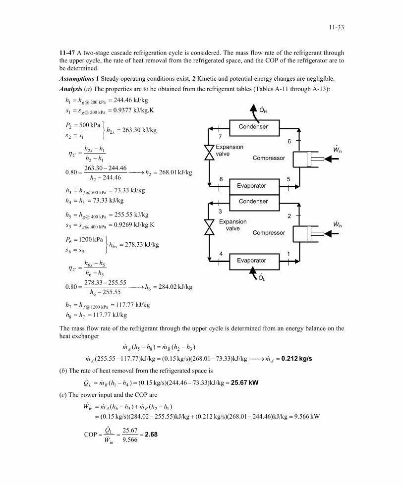
11-47 A two-stage cascade refrigeration cycle is considered. The mass flow rate of the refrigerant through the upper cycle, the rate of heat removal from the refrigerated space, and the COP of the refrigerator are to be determined. Assumptions 1 Steady operating conditions exist. 2 Kinetic and potential energy changes are negligible. Analysis (a) The properties are to be obtained from the refrigerant tables (Tables A-11 through A-13):
kJ/kg.K 9377.0kJ/kg 46.244
kPa 200 @1
kPa 200 @1
====
g
g
sshh
Win .Expansion
valve Compressor
Evaporator
Condenser
4
32
1
Win .Expansion
valve Compressor
Evaporator
Condenser
QH.
8
76
5
.QL
kJ/kg 30.263kPa 500
212
2 =
==
shss
P
kJ/kg 01.268
46.24446.24430.26380.0 2
2
12
12
=→−
−=
−−
=
hh
hhhh s
Cη
kJ/kg 33.73
kJ/kg 33.73
34
kPa 500 @3
====
hhhh f
kJ/kg.K 9269.0kJ/kg 55.255
kPa 400 @5
kPa 004 @5
====
g
g
sshh
kJ/kg 33.278kPa 1200
656
6 =
==
shss
P
kJ/kg 02.284
55.25555.25533.27880.0 6
6
56
56
=→−
−=
−−
=
hh
hhhh s
Cη
kJ/kg 77.117
kJ/kg 77.117
78
kPa 1200 @7
====
hhhh f
The mass flow rate of the refrigerant through the upper cycle is determined from an energy balance on the heat exchanger
kg/s 0.212=→−=−
−=−
AA
BA
mm
hhmhhm
&&
&&
kJ/kg)33.7301kg/s)(268. 15.0(kJ/kg)77.117.55255(
)()( 3285
(b) The rate of heat removal from the refrigerated space is
kW 25.67=−=−= kJ/kg)33.7346kg/s)(244. 15.0()( 41 hhmQ BL &&
(c) The power input and the COP are
kW 566.9kJ/kg)46.24401kg/s)(268. 212.0(kJ/kg)55.25502kg/s)(284. 15.0()()( 1256in
=−+−=−+−= hhmhhmW BA &&&
2.68===566.9
67.25COPin
L
WQ&
&
PROPRIETARY MATERIAL. © 2006 The McGraw-Hill Companies, Inc. Limited distribution permitted only to teachers and educators for course preparation. If you are a student using this Manual, you are using it without permission.
11-34
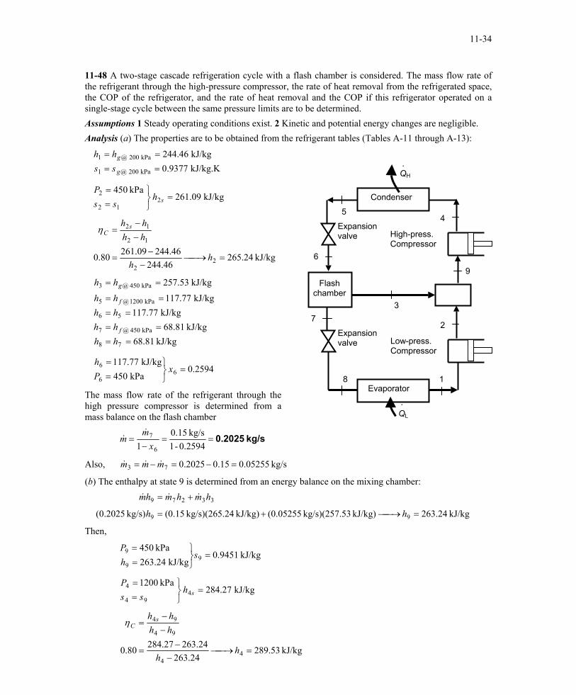
11-48 A two-stage cascade refrigeration cycle with a flash chamber is considered. The mass flow rate of the refrigerant through the high-pressure compressor, the rate of heat removal from the refrigerated space, the COP of the refrigerator, and the rate of heat removal and the COP if this refrigerator operated on a single-stage cycle between the same pressure limits are to be determined. Assumptions 1 Steady operating conditions exist. 2 Kinetic and potential energy changes are negligible. Analysis (a) The properties are to be obtained from the refrigerant tables (Tables A-11 through A-13):
kJ/kg.K 9377.0kJ/kg 46.244
kPa 200 @1
kPa 200 @1
====
g
g
sshh
7
Flash chamber
Expansion valve Low-press.
Compressor
Evaporator 8
9
2
1
Expansion valve High-press.
Compressor
Condenser
QH .
6
54
3
. QL
kJ/kg 09.261kPa 450
212
2 =
==
shss
P
kJ/kg 24.265
46.24446.24409.26180.0 2
2
12
12
=→−
−=
−−
=
hh
hhhh s
Cη
kJ/kg 81.68kJ/kg 81.68
kJ/kg 77.117kJ/kg 77.117
kJ/kg 53.257
78
kPa 450 @7
56
kPa 1200 @5
kPa 450 @3
====
====
==
hhhhhhhh
hh
f
f
g
2594.0kPa 450
kJ/kg 77.1176
6
6 =
==
xPh
The mass flow rate of the refrigerant through the high pressure compressor is determined from a mass balance on the flash chamber
kg/s 0.2025==−
=0.2594-1
kg/s 15.01 6
7
xm
m&
&
Also, kg/s 05255.015.02025.073 =−=−= mmm &&&
(b) The enthalpy at state 9 is determined from an energy balance on the mixing chamber:
kJ/kg 24.263kJ/kg) 53kg/s)(257. (0.05255kJ/kg) 24kg/s)(265. (0.15kg/s) 2025.0( 99
33279
=→+=
+=
hh
hmhmhm &&&
Then,
kJ/kg 9451.0kJ/kg 24.263
kPa 4509
9
9 =
==
shP
kJ/kg 27.284kPa 1200
494
4 =
==
shss
P
kJ/kg 53.289
24.26324.26327.28480.0 4
4
94
94
=→−
−=
−−
=
hh
hhhh s
Cη
PROPRIETARY MATERIAL. © 2006 The McGraw-Hill Companies, Inc. Limited distribution permitted only to teachers and educators for course preparation. If you are a student using this Manual, you are using it without permission.
11-35
The rate of heat removal from the refrigerated space is
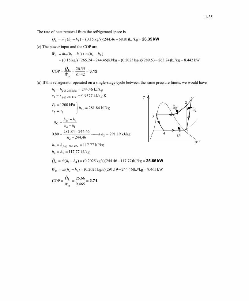
kW 26.35=−=−= kJ/kg)81.6846kg/s)(244. 15.0()( 817 hhmQL &&
(c) The power input and the COP are
kW 442.8kJ/kg)24.26353kg/s)(289. 2025.0(kJ/kg)46.24424kg/s)(265. 15.0()()( 94127in
=−+−=−+−= hhmhhmW &&&
3.12===442.8
35.26COPin
L
WQ&
&
(d) If this refrigerator operated on a single-stage cycle between the same pressure limits, we would have
kJ/kg.K 9377.0kJ/kg 46.244
kPa 200 @1
kPa 200 @1
====
g
g
sshh
T
QH
QL
Win ·
2
·
·
4
3
2
1
kJ/kg 84.281kPa 1200
212
2 =
==
shss
P
kJ/kg 19.29146.244
46.24484.28180.0 22
12
12
=→−
−=
−−
=
hh
hhhh s
Cη
s
kJ/kg 77.117
kJ/kg 77.117
34
kPa 1200 @3
==
==
hh
hh f
kW 25.66=−=−= kJ/kg)77.11746kg/s)(244. 2025.0()( 41 hhmQL &&
kW 465.9kJ/kg)46.24419kg/s)(291. 2025.0()( 12in =−=−= hhmW &&
2.71===465.9
66.25COPin
L
WQ&
&
PROPRIETARY MATERIAL. © 2006 The McGraw-Hill Companies, Inc. Limited distribution permitted only to teachers and educators for course preparation. If you are a student using this Manual, you are using it without permission.