numeriČka analiza zavarenog spoja uŠke za podizanje …
TRANSCRIPT
123
„ENGINEERING TECHNOLOGIES IN MANUFACTURING OF WELDED CONSTRUCTIONS AND PRODUCTS, SBW 2021“
NUMERIČKA ANALIZA ZAVARENOG SPOJA UŠKE ZA PODIZANJE TERETA
NUMERICAL ANALYSIS OF THE WELDED JOINT OF THE LIFTING
LUG
Sara Radojičić1, Pejo Konjatić2, Dorian Turk3, Josip Kačmarčik4
1 University of Slavonski Brod, Mechanical engineering faculty, Trg I. B. Mažuranić 2, 35000 Slavonski Brod, e-mail: [email protected] 2 University of Slavonski Brod, Mechanical engineering faculty, Trg I. B. Mažuranić 2, 35000 Slavonski Brod, e-mail: [email protected] 3 University of Slavonski Brod, Mechanical engineering faculty, Trg I. B. Mažuranić 2, 35000 Slavonski Brod, e-mail: [email protected] 4 University of Zenica, Mechanical engineering faculty, Fakultetska 1, 72000 Zenica, e-mail: [email protected]
Key words: fillet weld, lifting lug, finite element analysis, welded joints, numerical analysis Abstract: The finite element method is a very useful and practical method of predicting the highest concentrations of stresses and deflection of loaded structures including structures that are produced by the welding process where significant concentrations of stress occur. This paper analyzes the approaches to numerical modelling of the welded joint of the lifting lug weld. The results of this analysis were compared with the analytical calculation according to EN 1993-1-8 and the most economical approach to welded joint modelling was proposed in terms of the time needed to create a welded joint model with sufficient stress distribution accuracy and correlation with analytical calculation. INTRODUCTION
Welding is a technology of inseparable joining of materials used in the metalworking industry today. When the
additional material is melted, a large amount of heat is added, which causes the occurrence of uneven temperature fields in the joint. The result of uneven temperature fields is uneven expansion and contraction of the material, which leads to the occurrence of residual stresses and permanent deformation. Residual stresses can have a negative effect on the mechanical properties of the joint and cause deformation and cracks in the material, material fatigue and corrosion. They lead to changes in the shape and dimensions of welds, reduce strength and toughness and affect the microstructure of the material in the weld area. The consequences of residual stresses can be eliminated by various treatments of the materials, which increases the cost of the production process, but their effectiveness is questionable.
To avoid the occurrence of residual stresses, ideally it should be performed an analytical calculation of the welded joint. An alternative method is numerical modelling, which can be used to estimate residual stresses and strains in order to obtain the highest quality joint possible. Numerical simulations have become an important tool for predicting these phenomena, but the structures that can be simulated and the time over which they can be studied are always limited by computing power. Reducing the computational time and complexity of transient nonlinear problems such as the welding process is one of the active research areas in engineering. Many studies and papers have been published in this area. [1-4] The application of the finite element method to predict the thermal, material, and mechanical effects of welding is described in detail in various articles and papers [5]. The actual shape of the weld also appears to be a very important factor in the numerical modelling of welds [6].
It is necessary to choose the size of the finite elements in such a way that they provide a sufficiently accurate solution at the right time of the simulation. PROBLEM DESCRIPTION
A lifting lug is a support component consisting of a single plate of varying thickness. The thickness of the depends
on the weight of the load. A lifting lug is welded to a load-bearing structure and is used to connect to other support components. They are essential for any lifting operation. Without them, it would not be possible to transfer the material from one place to another in each given time. Since they are used to lift very heavy loads, everything must be precisely dimensioned and calculated to avoid failure. 2.1 Geometry and loading
T-joint welds are observed over the entire circumference of the weld. The dimensions of the sample for which the analysis was carried out are shown in Figure 1. The dimensions of the base plate are 300x150x30 mm, and a lifting lug with dimensions 200x200x20 mm is welded to it. The material of the base model is S355, and the welding material has a tensile strength of 510 MPa. The lifting lug is loaded with a force of 120 kN which is at an angle of 60° with respect to

124
„ENGINEERING TECHNOLOGIES IN MANUFACTURING OF WELDED CONSTRUCTIONS AND PRODUCTS, SBW 2021“
the reference axis. The base metal material is modelled based on its properties, i.e., the Young's modulus of elasticity for base metal is 210 GPa, the Poisson's ratio is 0,3, the yield strength is 355 MPa, and the tensile strength is 490 MPa.
Figure 1. Lifting lug with its dimensions and loads
NUMERICAL ANALYSIS
The numerical analysis of the welds of the lifting lug described above was carried out with the finite element method
using the Ansys Workbench software package [7]. The conducted numerical analysis used linear elastic material model. A comparison of the welds with and without the welded root was carried out. The numerical analysis is performed with tetrahedral and quadratic second-order finite elements. For the first analysis, a mesh with 15 mm second-order tetrahedral finite elements was used. The result is a mesh with 5995 finite elements and 10479 nodes for the case under a), 5965, and 10141 for the case under b) and 6430 and 10916 nodes for the case under c). Figure 2 shows the generated finite element mesh for all models.
a) b) c) Figure 2. Initial finite element mesh for all three cases
125
„ENGINEERING TECHNOLOGIES IN MANUFACTURING OF WELDED CONSTRUCTIONS AND PRODUCTS, SBW 2021“
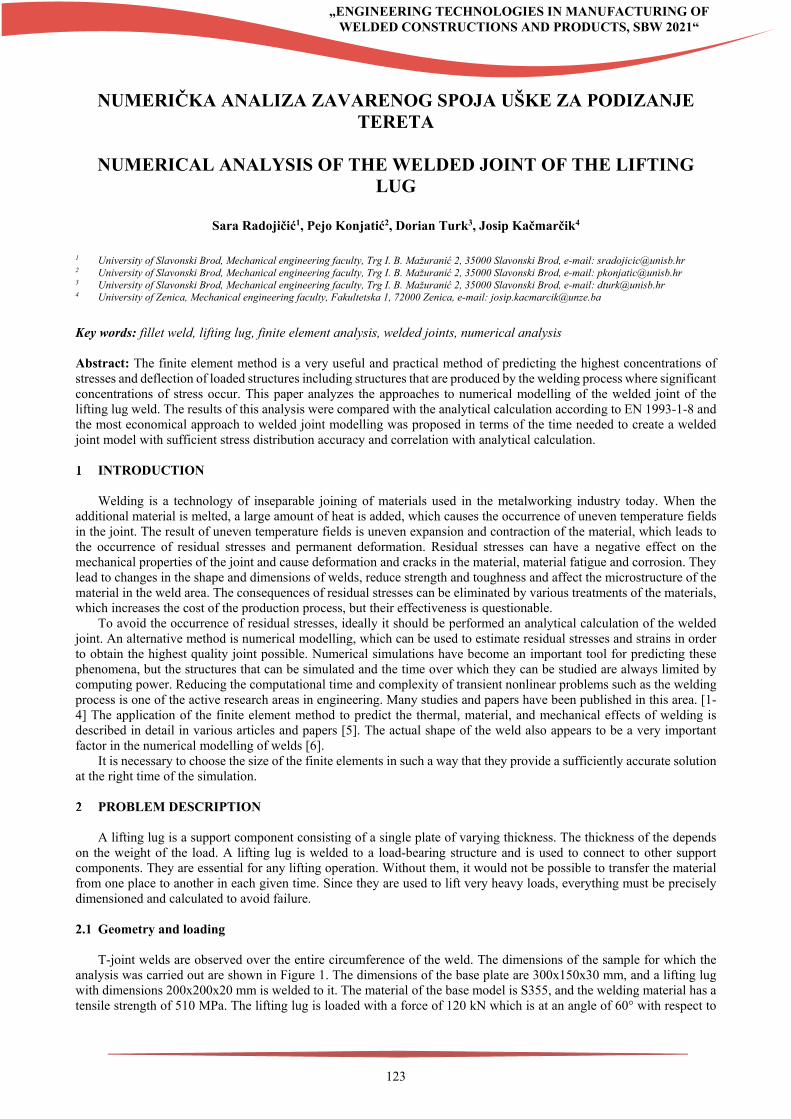
In addition to the finite element mesh shown, Figure 3 shows the finally obtained finite element mesh after convergence of the results. Mesh consists of tetrahedral and quadratic second-order finite elements ranging in size from 0,5 to 5 mm. Generated mesh resulted in 856038 finite elements and 1497032 nodes.
Figure 3. Finite element mesh after convergence
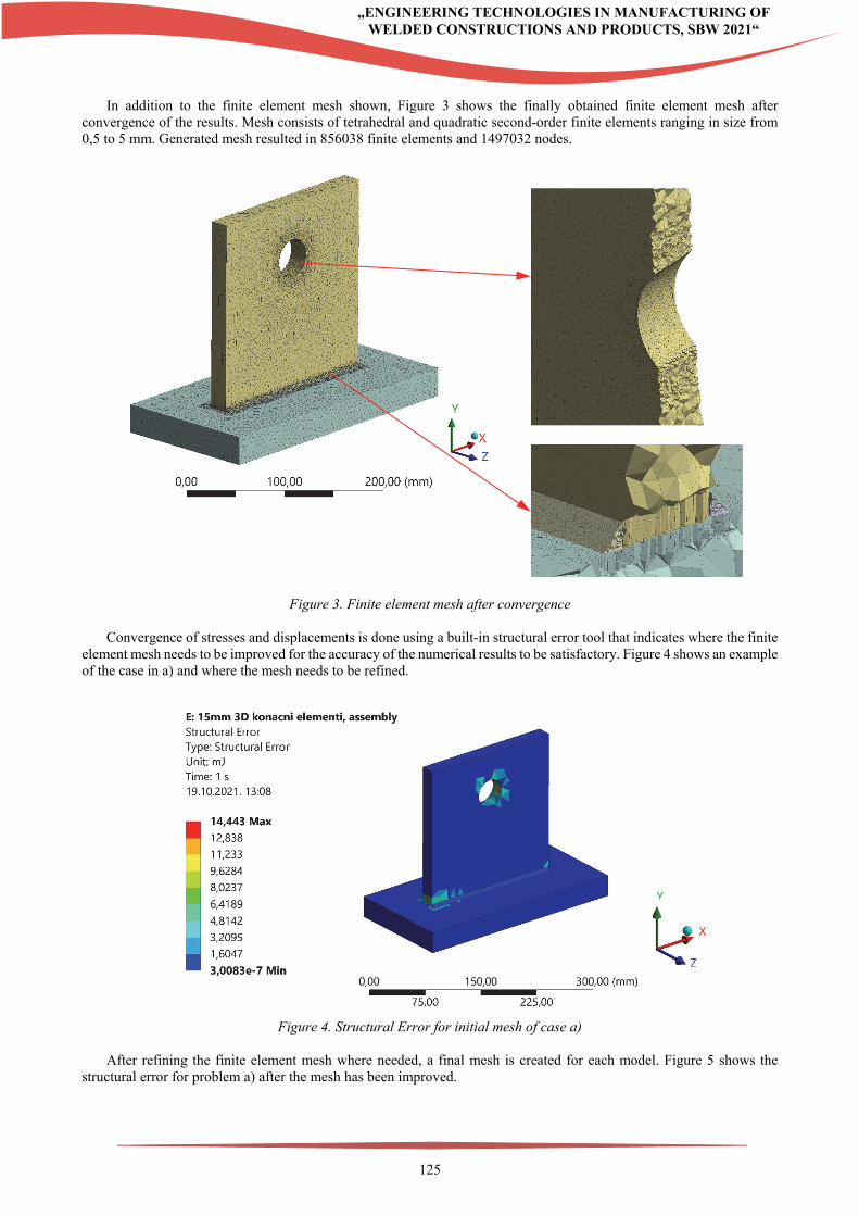
Convergence of stresses and displacements is done using a built-in structural error tool that indicates where the finite element mesh needs to be improved for the accuracy of the numerical results to be satisfactory. Figure 4 shows an example of the case in a) and where the mesh needs to be refined.
Figure 4. Structural Error for initial mesh of case a)
After refining the finite element mesh where needed, a final mesh is created for each model. Figure 5 shows the
structural error for problem a) after the mesh has been improved.
126
„ENGINEERING TECHNOLOGIES IN MANUFACTURING OF WELDED CONSTRUCTIONS AND PRODUCTS, SBW 2021“
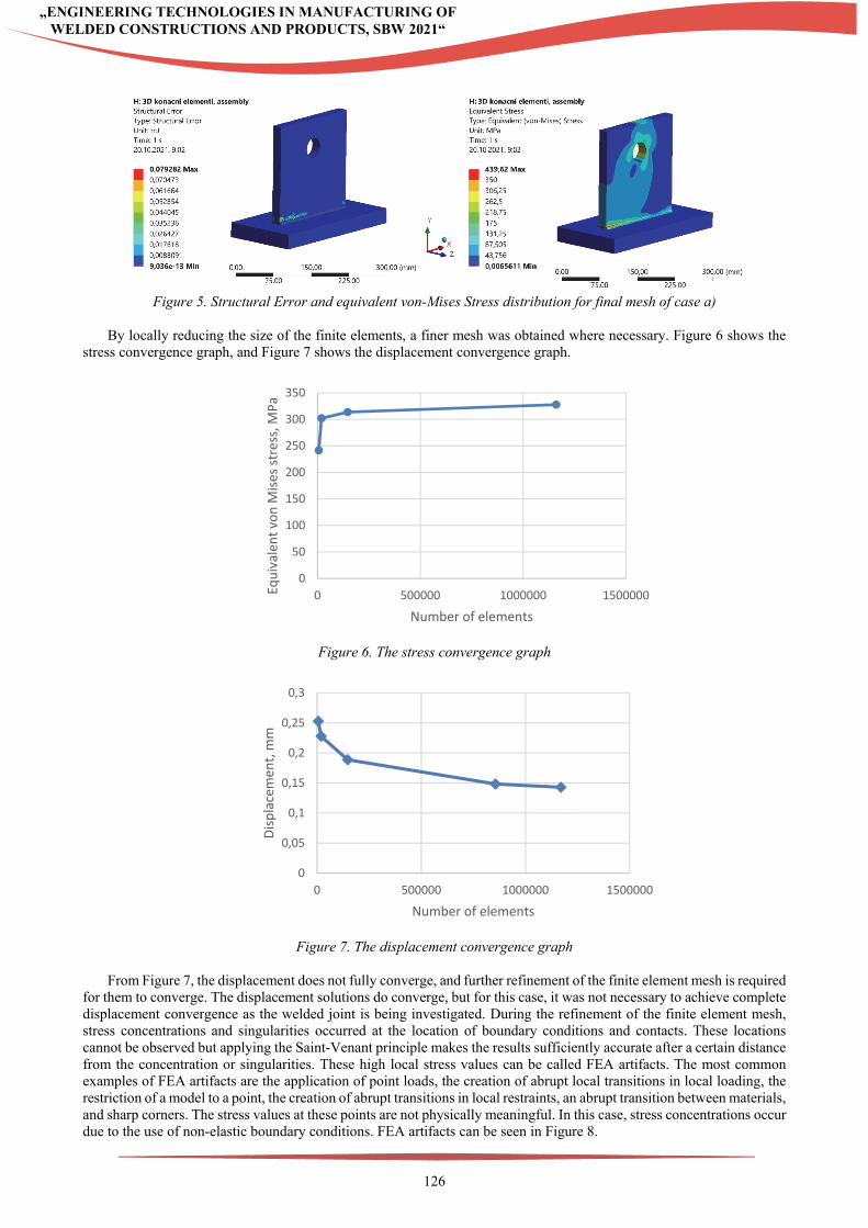
Figure 5. Structural Error and equivalent von-Mises Stress distribution for final mesh of case a)
By locally reducing the size of the finite elements, a finer mesh was obtained where necessary. Figure 6 shows the
stress convergence graph, and Figure 7 shows the displacement convergence graph.
Figure 6. The stress convergence graph
Figure 7. The displacement convergence graph
From Figure 7, the displacement does not fully converge, and further refinement of the finite element mesh is required
for them to converge. The displacement solutions do converge, but for this case, it was not necessary to achieve complete displacement convergence as the welded joint is being investigated. During the refinement of the finite element mesh, stress concentrations and singularities occurred at the location of boundary conditions and contacts. These locations cannot be observed but applying the Saint-Venant principle makes the results sufficiently accurate after a certain distance from the concentration or singularities. These high local stress values can be called FEA artifacts. The most common examples of FEA artifacts are the application of point loads, the creation of abrupt local transitions in local loading, the restriction of a model to a point, the creation of abrupt transitions in local restraints, an abrupt transition between materials, and sharp corners. The stress values at these points are not physically meaningful. In this case, stress concentrations occur due to the use of non-elastic boundary conditions. FEA artifacts can be seen in Figure 8.
0
50
100
150
200
250
300
350
0 500000 1000000 1500000Equivalen
t von M
ises stress, M
Pa
Number of elements
0
0,05
0,1
0,15
0,2
0,25
0,3
0 500000 1000000 1500000
Displacemen
t, mm
Number of elements
127
„ENGINEERING TECHNOLOGIES IN MANUFACTURING OF WELDED CONSTRUCTIONS AND PRODUCTS, SBW 2021“
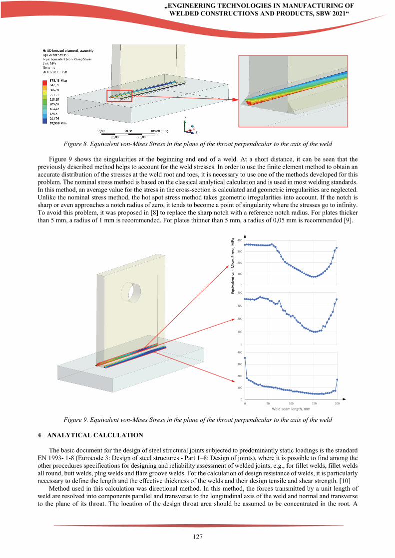
Figure 8. Equivalent von-Mises Stress in the plane of the throat perpendicular to the axis of the weld
Figure 9 shows the singularities at the beginning and end of a weld. At a short distance, it can be seen that the
previously described method helps to account for the weld stresses. In order to use the finite element method to obtain an accurate distribution of the stresses at the weld root and toes, it is necessary to use one of the methods developed for this problem. The nominal stress method is based on the classical analytical calculation and is used in most welding standards. In this method, an average value for the stress in the cross-section is calculated and geometric irregularities are neglected. Unlike the nominal stress method, the hot spot stress method takes geometric irregularities into account. If the notch is sharp or even approaches a notch radius of zero, it tends to become a point of singularity where the stresses go to infinity. To avoid this problem, it was proposed in [8] to replace the sharp notch with a reference notch radius. For plates thicker than 5 mm, a radius of 1 mm is recommended. For plates thinner than 5 mm, a radius of 0,05 mm is recommended [9].
0
100
200
300
400
0
100
200
300
400
0
100
200
300
400
0 50 100 150 200
Weld seam length, mm
Equivalent von‐M
ises Stress, M
Pa
Figure 9. Equivalent von-Mises Stress in the plane of the throat perpendicular to the axis of the weld
ANALYTICAL CALCULATION
The basic document for the design of steel structural joints subjected to predominantly static loadings is the standard
EN 1993- 1-8 (Eurocode 3: Design of steel structures - Part 1–8: Design of joints), where it is possible to find among the other procedures specifications for designing and reliability assessment of welded joints, e.g., for fillet welds, fillet welds all round, butt welds, plug welds and flare groove welds. For the calculation of design resistance of welds, it is particularly necessary to define the length and the effective thickness of the welds and their design tensile and shear strength. [10]
Method used in this calculation was directional method. In this method, the forces transmitted by a unit length of weld are resolved into components parallel and transverse to the longitudinal axis of the weld and normal and transverse to the plane of its throat. The location of the design throat area should be assumed to be concentrated in the root. A
128
„ENGINEERING TECHNOLOGIES IN MANUFACTURING OF WELDED CONSTRUCTIONS AND PRODUCTS, SBW 2021“
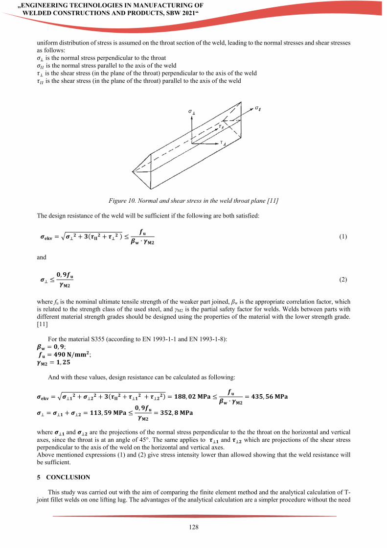
uniform distribution of stress is assumed on the throat section of the weld, leading to the normal stresses and shear stresses as follows: 𝜎 is the normal stress perpendicular to the throat 𝜎 is the normal stress parallel to the axis of the weld 𝜏 is the shear stress (in the plane of the throat) perpendicular to the axis of the weld 𝜏 is the shear stress (in the plane of the throat) parallel to the axis of the weld
Figure 10. Normal and shear stress in the weld throat plane [11]
The design resistance of the weld will be sufficient if the following are both satisfied:
𝝈𝐞𝐤𝐯 𝝈 𝟐 𝟑 𝝉𝐈𝐈𝟐 𝝉 𝟐 𝒇𝐮
𝜷𝐰 ∙ 𝜸𝐌𝟐 (1)
and
𝝈𝟎,𝟗𝒇𝐮𝜸𝐌𝟐
(2)
where fu is the nominal ultimate tensile strength of the weaker part joined, βw is the appropriate correlation factor, which is related to the strength class of the used steel, and γM2 is the partial safety factor for welds. Welds between parts with different material strength grades should be designed using the properties of the material with the lower strength grade. [11]
For the material S355 (according to EN 1993-1-1 and EN 1993-1-8): 𝜷𝐰 𝟎,𝟗; 𝒇𝐮 𝟒𝟗𝟎 𝐍/𝐦𝐦𝟐; 𝜸𝐌𝟐 𝟏,𝟐𝟓
And with these values, design resistance can be calculated as following:
𝝈𝐞𝐤𝐯 𝝈 𝟏𝟐 𝝈 𝟐
𝟐 𝟑 𝝉𝐈𝐈𝟐 𝝉 𝟏𝟐 𝝉 𝟐
𝟐 𝟏𝟖𝟖,𝟎𝟐 𝐌𝐏𝐚𝒇𝐮
𝜷𝐰 ∙ 𝜸𝐌𝟐𝟒𝟑𝟓,𝟓𝟔 𝐌𝐏𝐚
𝝈 𝝈 𝟏 𝝈 𝟐 𝟏𝟏𝟑,𝟓𝟗 𝐌𝐏𝐚𝟎,𝟗𝒇𝐮𝜸𝐌𝟐
𝟑𝟓𝟐,𝟖 𝐌𝐏𝐚
where 𝝈 𝟏 and 𝝈 𝟐 are the projections of the normal stress perpendicular to the the throat on the horizontal and vertical axes, since the throat is at an angle of 45°. The same applies to 𝝉 𝟏 and 𝝉 𝟐 which are projections of the shear stress perpendicular to the axis of the weld on the horizontal and vertical axes. Above mentioned expressions (1) and (2) give stress intensity lower than allowed showing that the weld resistance will be sufficient. CONCLUSION
This study was carried out with the aim of comparing the finite element method and the analytical calculation of T-
joint fillet welds on one lifting lug. The advantages of the analytical calculation are a simpler procedure without the need

129
„ENGINEERING TECHNOLOGIES IN MANUFACTURING OF WELDED CONSTRUCTIONS AND PRODUCTS, SBW 2021“
to create a model and use a computer. This method is suitable for engineers who have a comprehensive knowledge of the Eurocode 3 standard and know how to apply it correctly. In finite element analysis three types of welds modelling were compared. The first method, which is also the most accurate, uses contacts. The second method, where the whole problem is created as one model, gives very similar results to the contact model, but the computation time is much shorter, as is the time and complexity of meshing. The disadvantage of the second approach is the impossibility of isolating the weld geometry and observing only at its results. The third model uses an identical approach to the second model, but a case of welded root was observed. The finite element method is used for much more complex models where a manual calculation would take too much time and it is necessary to be familiar with the method. As a continuation of this investigation, it is also planned to carry out experiments to additionally validate the results obtained by the finite element analysis. Based on the results, it can be concluded that both calculation methods corelate and there are no major discrepancies in the results. REFERENCES
[1] Perić, M., Tonković, Z., Rodić, A., Surjak M., Garašić, I.; Boras, I., Švaić, S. (2014). Numerical analysis and
experimental investigation of welding residual stresses and distortions in a T-joint fillet weld. Materials & Design 53, 1052-1063.
[2] Deng, D., Liang, W., Murakawa, H. (2007). Determination of welding deformation in filletwelded joint by means of numerical simulation and comparison with experimental measurements. J Mater Process Technol, 183, 219–25.
[3] Lee, CH., Chang, KH. (2008). Three-dimensional finite element simulation of residual stresses in circumferential welds of steel pipe diameter effects. Mater Sci Eng A 487, 210–8.
[4] Deng, D. (2009). FEM prediction of welding residual stress and distortion in carbon steel considering phase transformation effects. Mater Des 30, 359–66.
[5] Lindgren LE. (2006). Numerical modelling of welding. Comput Methods Appl Mech Eng, 195(4 8–4 9), 6710–6736. [6] Efimenko, LA., Semin EE. (2006). Effects of weld shape and defect size on the stress and strain in a welded joint to
a vertical steel vessel. Chem Pet Eng 42(9–10), 538–542. [7] Analysis System, Ansys Workbench, Release 2021, ANSYS Inc., 2020. [8] Fricke, W. (2012). IIW Recommendations for the Fatigue Assessment by Notch Stress Analysis for Welded
Structures. [9] Lindqvist, A., Henrik N. (2016). Effective notch stress analysis of transverse attachments in steel bridges. Master’s
Thesis in the Master’s Programme Structural Engineering and Building Technology, Chalmers university of technology, Gothenburg, Sweden
[10] Krejsa, M., Brozovsky, J., Mikolasek, D., Parenica P., Flodr, J., Materna, A., Halama, R., Kozak, J. (2018). Numerical modeling of steel fillet welded joint. Advances in Engineering Software 117, 59-69.
[11] Eurocode 3: Design of Steel Structures. London: BSI, 2005. Print.