nusaf - bs&b · • available “ce” marked or asme ... nf-7rs or preassembled safety head...
TRANSCRIPT

1
NuSaf™
Scored Forward Acting Rupture Disks
Catalog # 77-5003
BSBsystems.com | BSB.ieVisit our website for the most complete, up-to-date information

2
(Activated)
XN-85TM Precision Scored, High Performance Rupture DisksThe XN-85 is specially manufactured by forming the disk first and then scoring. This creates a minimally stressed score pattern offering optimum service life and an extended operating pressure limit of 85% of marked burst pressure or 90% of minimum burst pressure, even under cyclic conditions. Consult us with your particular operating requirements.
Features• Solid metal• Precision scored • Designed for non-fragmentation• Withstands full vacuum without support• Operates up to 85% of the disk’s marked pressure or 90% of
minimum burst pressure• Liquid and gas service (acceptable for liquid service with gas
driven liquid conditions; consult factory)• Damage safety ratio <1• Optimum forward acting disk for pulsating or cycling
conditions• 0%, -5% and -10% manufacturing design range• For use in pretorqued BS&B safety heads type NFI-7RS and
NF-7RS or preassembled safety head types NX-7R and NF-7R.
Burst ToleranceMarked burst pressure Burst tolerance
< 40 psig (2.76barg) + 2 psig (0.138barg)
> 40 psig (2.76 barg) + 5%
Material Maximum RecommendedTemperature
Aluminum 250°F 121°C
Nickel (alloy 200) 750°F 399°C
Monel® (alloy 400) 900°F 482°C
Inconel® (alloy 600) 1100°F 593°C
316 stainless steel 900°F 482°C
Hastelloy® C-276 (alloy C-276) 900°F 482°C
Disk Size Aluminum Nickel Alloy 200 Inconel® Alloy 600 Monel® Alloy 400 316ss
in mmpsig barg psig barg psig barg psig barg psig barg
Min Max Min Max Min Max Min Max Min Max Min Max Min Max Min Max Min Max Min Max
1 25 113 188 8 13 188 1500 13 103 225 1800 16 124 225 1500 16 103 335 1800 23 124
1.5 40 81 135 6 9 135 1500 9 103 165 1800 11 124 165 1500 11 103 250 1800 17 124
2 50 68 113 5 8 113 1350 8 93 135 1800 9 124 135 1350 9 93 200 1800 14 124
3 80 54 90 4 6 90 1250 6 86 108 1600 8 110 108 1250 8 86 160 1600 11 110
4 100 45 75 3 5 75 1200 5 82 90 1400 6 97 90 1200 6 83 135 1400 9 97
6 150 36 60 3 4 60 1100 4 76 72 1150 5 79 72 1100 5 76 125 1200 9 83
8 200 - - - - 53 1000 4 69 63 1050 4 72 63 1000 4 69 120 1100 8 76
10 250 - - - - 45 900 3 62 54 950 4 66 54 900 4 62 115 1000 8 69
12 300 - - - - 41 750 13 52 50 850 4 59 50 750 4 52 110 900 8 62
14 350 - - - - 35 500 2 34 42 700 3 48 42 500 3 34 100 800 7 55
16 400 - - - - 33 270 2 19 39 350 3 24 39 270 3 19 90 400 6 28
18 450 - - - - 33 200 2 14 38 260 3 18 38 200 3 14 85 300 6 21
20 500 - - - - 32 170 2 12 36 220 3 15 36 170 3 12 80 250 6 17
24 600 - - - - 30 140 2 9 33 180 2 12 33 140 2 9 70 200 5 14
Optional liner; liners are available in all sizes on the process or downstream side (or for both; consult factory). Fluoropolymer film application range -40°F (-40°C) to 500°F (260°C)
Manufacturing Design Range (MDR)The choice of a 0%, -5% or -10% MDR is available. The total range is placed on the minus side of requested burst pressure.

3
Type XTTM Advanced Rupture Disk Performance from a Forward Acting, Tension Loaded Design
Burst Pressure Capabilities at 72°F (22°C)Nominal
Size Aluminum Nickel Alloy 200 & Tantalum
Inconel® Alloy 600 & Monel® alloy 400 316ss Hastelloy® Alloy
C-276, C-22
in mmpsig barg psig barg psig barg psig barg psig barg
min max min max min max min max min max min max min max min max min max min max
1 25 80 1450 6 100 165 1450 11 100 165 1450 11 100 175 1450 12 100 240 1450 17 100
1.5 40 55 1450 4 100 115 1450 8 100 115 1450 8 100 125 1450 9 100 176 1450 12 100
2 50 45 1450 3 100 105 1450 7 100 105 1450 7 100 115 1450 8 100 160 1450 11 100
3 80 45 1300 3 100 90 1300 6 90 90 1300 6 90 100 1300 7 90 140 1300 10 90
4 100 40 1150 3 79 90 1150 6 79 90 1150 6 79 95 1150 7 79 140 1150 10 79
6 150 40 1040 3 72 90 1040 6 71 90 1040 6 71 90 1040 6 72 130 1040 9 72
8 200 40 960 3 66 85 960 6 66 85 960 6 66 90 960 6 66 130 960 9 66
10 250 - - - - 85 840 6 58 85 840 6 58 90 840 6 58 125 840 9 58
Optional liner: A flurocarbon film liner is available as an option on the process side of the XT disk. fluoropolymer film application range -40°F to 500°F (-40°C to 260°C)
Material Maximum Recommended Temperature
Nickel alloy 200 750ºF 399ºC
Monel® alloy 400 900ºF 482ºC
Inconel® alloy 600 1100ºF 593ºC
Stainless steel 316 900ºF 482ºC
Hastelloy® (alloy C-276 or C-22) 900ºF 482ºC
Aluminum 250ºF 121ºC
Tantalum 500ºF 260ºC
Marked Burst Pressure Burst Tolerance< 40 psig (2.76barg) + 2 psig (0.138barg)
> 40 psig (2.76 barg) + 5%
Burst Tolerance
Features• Sizes 1-10 inches (25-250 mm)• Seven standard materials; wide range of corrosion resistance -
Refer to the material temperature table• ‘X’ shaped score pattern; designed for non-fragmentation;
excellent for relief valve isolation.• Smooth surface on process side; resistant to product
accumulation• Operates up to 80% of marked burst pressure or 85% of
minimum burst pressure• Designed for gas service or liquid service• High flow capacity / low flow resistance: certified for gas and
liquid service • Fail safe: design safety ratio < 1 • 1 piece solid metal construction; excellent leak tightness• Withstands full vacuum without support• Available “CE” marked or ASME stamped (UD)• For use in pretorqued BS&B safety heads type NFI-7RS and
NF-7RS or preassembled safety head types NX-7R and NF-7R
A 90% operating pressure ratio may apply under static operationg conditions; consult factory

4
Type XBTM
Rupture Disks for High PressureThe XB rupture disk (also referred to as “Scored B” or “SCD B”) is a non-fragmenting, high pressure rupture disk that opens along score lines. The XB offers a broader range of burst pressures and sizes.
Burst Tolerance
Manufacturing Design Range (MDR)The XB is available with either -5% or -10% MDR. Consult BS&B for manufacturing design ranges less than -5%.
Material Maximum Recommended Temperature
Nickel alloy 200 750ºF 399ºC
Monel® alloy 400 900ºF 482ºC
Inconel® alloy 600 1100ºF 593ºC
Stainless steel 316 900ºF 482ºC
Hastelloy® (alloy C-276 or C-22) 900ºF 482ºC
Aluminum 250ºF 121ºC
Tantalum 500ºF 260ºC
XB Disk Specifications Minimum / Maximum Pressure Ratings at 72°F (22°C)
Disk Size Aluminum Nickel alloy 200 Inconel® Alloy 600 Monel® Alloy 400 Hastelloy® Alloy C 276 and 316ss
in mmpsig barg psig barg psig barg psig barg psig barg
Min Max Min Max Min Max Min Max Min Max Min Max Min Max Min Max Min Max Min Max
1 25 125 1000 9 69 250 4000 17 276 250 6000 17 414 250 4000 17 276 300 6000 21 414
1.5 40 100 750 7 52 200 2600 14 179 200 4000 14 276 200 2600 14 179 250 4000 17 276
2 50 85 500 6 35 175 2300 12 159 175 3500 12 241 175 2300 12 159 225 3500 16 241
3 80 75 300 5 21 150 2000 10 138 150 3000 10 207 150 2000 10 138 175 3000 12 207
4 100 70 250 5 17 135 1750 9 121 135 2500 9 172 135 1750 9 121 150 2500 10 172
6 150 60 200 4 14 125 1250 9 86 125 2000 9 138 125 1250 9 86 - - - -
8 200 - - - - 110 1100 8 76 110 1750 8 121 110 1100 8 76 - - - -
10 250 - - - - 100 1000 7 69 100 1500 7 103 100 1000 7 69 - - - -
12 300 - - - - 90 850 6 59 90 1250 6 86 90 850 6 59 - - - -
14 350 - - - - 80 650 6 45 80 1000 6 69 - - - - - - - -
16 400 - - - - 75 525 5 36 75 800 5 55 - - - - - - - -
18 450 - - - - 70 400 5 28 70 600 5 41 - - - - - - - -
20 500 - - - - 65 350 5 24 65 500 5 35 - - - - - - - -
24 600 - - - - 60 175 4 12 60 250 4 17 - - - - - - - -
Optional liner: A flurocarbon film liner is available as an option on the process side of the XT disk. Fluoropolymer film application range -40°F to 500°F (-40°C to 260°C)
Marked Burst Pressure Burst Tolerance< 40 psig (2.76barg) + 2 psig (0.138barg)
> 40 psig (2.76 barg) + 5%
Features• Sizes 1 through 24 inches (25 through 600 mm)• Six standard materials; wide range of corrosion resistance• ‘X’ shaped score pattern; designed for non-fragmentation,
excellent for relief valve isolation• Smooth surface on inlet side; resistant to product
accumulation• Designed for gas or liquid service• High flow capacity / low flow resistance: certified Krgl of 0.4
and high flow area in all sizes• Fail safe: design safety ratio < 1 means a damaged XB disk
will burst at or below its rated burst pressure• 1 piece solid metal construction; excellent leak tightness• Vacuum resistant; no additional support required• 3-D tag; always visible with standard pipe flanges
to verify disk description and confirm correct installation direction
• Available “CE” marked or “UD” stamped
• For use in pretorqued BS&B safety heads type NFI-7RS and NF-7RS or preassembled safety head types NX-7R and NF-7R

5
LCNTM Low Pressure Rupture Disk
The type LCN flat rupture disk uses composite technology to achieve low burst ratings from resistant materials that shall be selected to suit application service conditions.
Features• Flat composite metal construction• Fluorocarbon film seal • Can withstand full vacuum • Operates up to 80% of the minimum burst pressure • Suitable for gas and liquid applications• Damage safety ratio < 1 • Standard materials of construction 316ss / fluorocarbon film
/ 316ss - Consult BS&B for other materials• For use in pretorqued BS&B safety heads type NFI-7RS and
NF-7RS or preassembled safety head types NX-7R and NF-7R
LCN Specifications: Minimum / Maximum Disk Burst Pressures at 72°F (22°C)
Disk Size 316ss / Fluorcarbon Film / 316ss
in mmpsig barg
Min Max Min Max
1 25 14 188 1 13
1.5 40 12 135 0.8 9
2 50 7 113 0.5 8
3 80 5 90 0.4 6
4 100 5 75 0.4 5
6 150 3 60 0.2 4
8 200 3 53 0.2 4
10 250 3 45 0.2 3
12 300 3 41 0.2 3
14 350 3 35 0.2 2
16 400 3 33 0.2 2
18 450 3 33 0.2 2
20 500 3 32 0.2 2
24 600 3 30 0.2 2
The requested burst pressure is the marked burst pressure
Marked Burst Pressure Burst Tolerance
< 7 psig (0.48 barg) +1 psig (0.069 barg)
< 15 psig (1.03 barg) +1.5 psig (0.1 barg)
15 < 40 psig (2.76 barg)> 40 psig (2.76 barg)
+2 psig (0.138 barg)+ 5%
Recommended Temperature Limits
Minimum -40°F -40°C
Maximum 400°F 204°C
Vacuum and Back Pressure ResistanceAll burst pressures at or above 45 psig (3.1barg) allow the LCN disk to resist full vacuum. At lower burst pressures the LCN disk will resist partial vacuum up to the equivalent of 35% of the marked burst pressure. Greater vacuum resistance can be provided by the NXV-7R™ safety head which has an integral vacuum support.
For back pressure resistance exceeding 15 psi (1.03bar) the NXV-7R safety head shall be used. Consult BS&B for maximum back pressure resistance. The NXV-7R safety head with integral vacuum support will reduce the free flow area by up to 40%.
Marked Burst Pressure MDR
> 40 psig (2.76 barg) -5% or -10%
> 15 psig (1.03 barg) and 140 psig (2.76 barg) -10%
< 15 psig (2.03 barg) 0%**
(Activated)
Manufacturing Design Range (MDR)

6
Pretorqued safety head technology provides superior performance for demanding applications. The features of all pretorqued safety heads that drive this user preference are:
• Enhanced leak tightness; pretorqued cap-screws energize the seal between the rupture disk and safety head, minimizing reliance on companion flange stud torque to ensure proper sealing.
• Simple modular installation of pressure relief device; designed to be assembled in a controlled workshop environment with the rupture disk & safety head assembly then brought to the point of installation as a modular unit. (Both ASME and EN Standards define the combination of a rupture disk & safety head as the pressure relief device.)
• Inspection capability; while the rupture disk and safety head remain combined, the device may be removed from service for inspection and reinstalled provided the pretorqued cap-screws remain in position.
Features of Pretorqued Safety Heads Types
NFI-7RSTM, NF-7RSTM, and NXI-7RSTM
• Pretorqued cap screws or bolts to energize the seal between the rupture disk and safety head, independent of companion flange bolt torque
• Three asymmetric locating pins center the rupture disk within the safety head, which ensures correct direction of disk installation and optimizes flow
• Rupture disk dome fully protected within safety head inlet to avoid damage when installed into piping system
• Proprietary ‘bite seal’ to optimize sealing between rupture disk and safety head process side. Standard for nominal size 2 inch (50 mm) and larger standard in all sizes of SRI-7RS safety heads.
• Spiral finish on inlet and outlet enhances disk gasket interface seal performance*
*ASME / ANSI B165 gasket sealing surface is standard
• J-bolt providing constant visual confirmation of correct dimension of installation
• Available in sizes 1-8 inches (25-1000mm)
Bite Type Seal
Pretorqued safety heads for scored forward acting rupture disks
Bite type seal for NFI-7RSTM , NXI-7RSTM
and NF-7RSTm Safety Heads
NF-7R and NX-7RTM Safety HeadsThe NF-7R™ and NX-7R™ Safety Head design incorporates several features which allow easy installation. The NF-7R and NX-7R Safety Heads fits inside the studs of two companion flanges. Asymmetric alignment pins in the Safety Head mate with location holes in the rupture disk to ensure centering and orientation of the disk. The flat seat design, in combination with a metal-to-metal “bite-type” seal, provides a leak-tight system. The NF-7R and NX-7R Safety Heads are easily pre-assembled with side lugs (see photograph below).

7
NFI-7RS Safety Head
NFI-7RS Safety Head Specifications
Size Safety Head Flange Rating Safety Head Flange Thickness
DimensionsA
DimensionsB
in mm ASME / ANSI EN JIS in mm in mm in mm
1 25 150/300/600 10/16/25/40 10/16/20/30/40 1.5 38 2.85 67 3.36 85
1.5 40 150/300/600 10/16/25/40 10/16/20/30/40 1.7 43 3.76 86 4 104
2 50 150/300/600 10/16/25/40 10/16/20/30/40 1.9 48 4.53 105 4.5 115
3 80 150/300/600 10/16/25/40 16/20/30/40 2.2 55 5.83 133 6 148
4 100 150/300 10/16/25/40 16/20/30/40 2.9 73 7.07 159 7 180
6 150 150/300 10/16/25/40 10/16/20/30 3.6 92Flower petal 9.75”
(248 mm) ODFlower petal 9.75”
(248 mm) OD
8 200 150/300 10/16/25/40 16/20/30 3.8 95Flower petal 12.12”
(308 mm) ODFlower petal 12.12”
(308 mm) OD
A
B
NFI-7RSTM
Pretorqued Safety Heads
Features• Bite seal in all sizes; proprietary feature which enhances leak
tightness• Light weight; manufactured from a casting, the NFI-7RS takes
advantage of advanced metal flow modeling to achieve its light construction and rigid strength.
• Self centering; the unique perimeter shape of the NFI-7RS is self centering between ASME / ANSI B16.5, EN, and JIS specification companion flanges, optimizing flow.
• Hexagon head pretorque capscrews; supplied with the NFI-7RS safety head, high tensile stainless steel capscrews allow installation using standard workshop tools.
• Accessible capscrews; visible after installation of the NFI-7RS safety head between companion flanges, the user can conveniently inspect for proper installation.
• Multiple flange rating; each nominal size NFI-7RS safety head can be installed between ASME/ANSI B16.5, EN, JIS (except 3” / 80mm and 4”/ 100mm JIS10) companion flanges. A single safety head held in inventory per nominal size will support multiple applications.
• Available in sizes 1-8 inches (25-1000mm) Note: The NFI-7RS safety head is US & International Patent Pending.
Materials Available• Aluminum• Carbon steel• 316ss
• Inconel®• Monel®• Hastelloy C®
Consult factory for availability of other materials
Rupture Disk Safety HeadXN85, XT, XB, LCN NFI-7RS

8
NF-7RSTM
Pretorqued Safety Heads
Features• Insert type safety heads that fit inside the bolt circle of
companion flanges• Pretorqued design, cap screws energize the seal between
the rupture disk and safety head, independent of companion flange bolt arrangement
• Positive locating pins center the disk correctly in the safety heads, thus eliminating disk slippage and possible incorrect installation
• Bite seal sizes 2” (50mm) and larger• For extra protection, a J-bolt is standard
on the safety head inlets. The safety heads can only fit between the companion flanges in the one direction that allows the J-bolt to mate with the drilled hole in the companion flange inlet. Correct flow direction is thus assured
• Disk dome protected by safety head outlet• Available in sizes 1-40 inches (25-
1000mm) (NF-7RS)
Materials Available
NF-7RS Safety Head
A
A
• Aluminum• Carbon steel• 316ss
• Inconel®• Monel®• Hastelloy C®
Consult factory for availability of other materials
Rupture Disk Safety HeadXN85, XT, XB, LCN NF-7RS
NF-7RSTM Safety Head DimensionsNominal
Size Safety Head Flange Rating Overall Height
Outside Dimensions Shape
in mm ANSI DIN JIS in mm A
1 25150 - - 1.5 38 OD 2.6 in (67 mm) square
300/600 10/16/25/40 10/16/20/30/40 1.5 38 OD 2.9 in (73 mm) square
1.5 40150 - 10/16/20 1.7 43 OD 3.4 in (86 mm) square
300/600 10/16/25/40 30/40 1.7 43 OD 3.7 in (95 mm) square
2 50 150/300/600 10/16/25/40 10/16/20/30/40 1.9 48 OD 4.1 in (104 mm) square
3 80150/300/600 10/16/25/40 10/16/20/40 2.2 55 OD 5.2 in (133 mm) square
- - 10 2.2 55 OD 5.2 in (132 mm) square
4 100
150/300 10/16/25/40 16/20/30/40 2.9 73 OD 6.2 in (158 mm) square
- - 10 2.9 73 OD 6.2 in (158 mm) square
600 - - 2.6 65 OD 7.6 in (192 mm) round
6 150150/300 10/16/25/40 10/30/40 3.6 92 OD 9.8 in (248 mm) round
600 - - 4.5 114 OD 10.4 in (264 mm) round
8 200 150/300 - - 3.8 97 OD 12.0 in (305 mm) round
10 250 150/300 - - 4.3 110 OD 14.1 in (359 mm) round
12 300150 - - 4.8 121 OD 16.0 in (406 mm) round
300 - - 5.3 133 OD 16.5 in (419 mm) round
14 350150 - - 5.3 133 OD 17.8 in (451 mm) round
300 - - 5.9 149 OD 19.6 in (483 mm) round
16 400150 - - 6.4 162 OD 20.1 in (511 mm) round
300 - - 7.1 181 OD 21.1 in (536 mm) round
18 450150 - - 7.4 187 OD 22.8 in (578 mm) round
300 - - 7.9 200 OD 23.4 in (594 mm) round
20 500150 - - 8.4 241 OD 24.8 in (629 mm) round
300 - - 8.6 219 OD 25.6 in (651 mm) round
24 600150 - - 10.3 260 OD 29.5 in (749 mm) round
300 - - 10.8 273 OD 30.4 in (772 mm) round
9
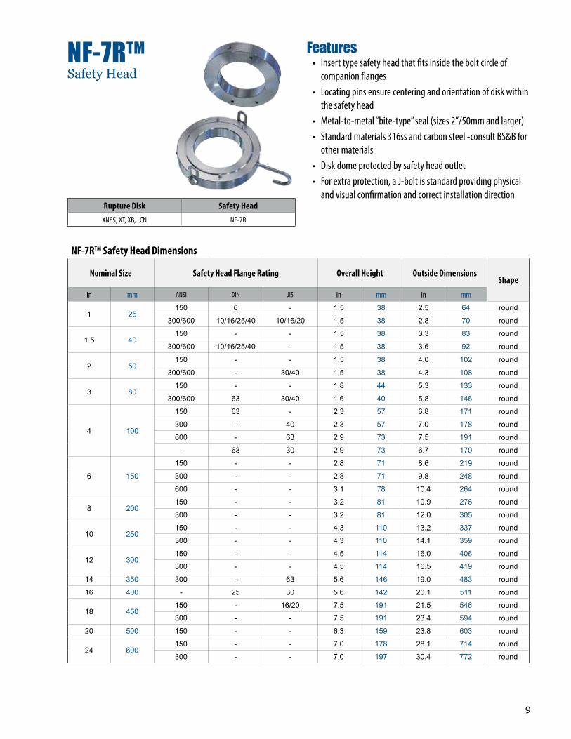
NF-7RTM
Safety Head
Rupture Disk Safety HeadXN85, XT, XB, LCN NF-7R
Features• Insert type safety head that fits inside the bolt circle of
companion flanges• Locating pins ensure centering and orientation of disk within
the safety head• Metal-to-metal “bite-type” seal (sizes 2”/50mm and larger)• Standard materials 316ss and carbon steel -consult BS&B for
other materials• Disk dome protected by safety head outlet• For extra protection, a J-bolt is standard providing physical
and visual confirmation and correct installation direction
NF-7RTM Safety Head Dimensions
Nominal Size Safety Head Flange Rating Overall Height Outside DimensionsShape
in mm ANSI DIN JIS in mm in mm
1 25150 6 - 1.5 38 2.5 64 round
300/600 10/16/25/40 10/16/20 1.5 38 2.8 70 round
1.5 40150 - - 1.5 38 3.3 83 round
300/600 10/16/25/40 - 1.5 38 3.6 92 round
2 50150 - - 1.5 38 4.0 102 round
300/600 - 30/40 1.5 38 4.3 108 round
3 80150 - - 1.8 44 5.3 133 round
300/600 63 30/40 1.6 40 5.8 146 round
4 100
150 63 - 2.3 57 6.8 171 round
300 - 40 2.3 57 7.0 178 round
600 - 63 2.9 73 7.5 191 round
- 63 30 2.9 73 6.7 170 round
6 150
150 - - 2.8 71 8.6 219 round
300 - - 2.8 71 9.8 248 round
600 - - 3.1 78 10.4 264 round
8 200150 - - 3.2 81 10.9 276 round
300 - - 3.2 81 12.0 305 round
10 250150 - - 4.3 110 13.2 337 round
300 - - 4.3 110 14.1 359 round
12 300150 - - 4.5 114 16.0 406 round
300 - - 4.5 114 16.5 419 round
14 350 300 - 63 5.6 146 19.0 483 round
16 400 - 25 30 5.6 142 20.1 511 round
18 450150 - 16/20 7.5 191 21.5 546 round
300 - - 7.5 191 23.4 594 round
20 500 150 - - 6.3 159 23.8 603 round
24 600150 - - 7.0 178 28.1 714 round
300 - - 7.0 197 30.4 772 round

10
NFI-7RS Safety Head Specifications
Size Safety Head Flange Rating Safety Head Flange Thickness
DimensionsA
DimensionsB
in mm ASME / ANSI EN JIS in mm in mm in mm
1 25 150/300/600 10/16/25/40 10/16/20/30/40 1.5 38 2.85 67 3.36 85
1.5 40 150/300/600 10/16/25/40 10/16/20/30/40 1.7 43 3.76 86 4 104
2 50 150/300/600 10/16/25/40 10/16/20/30/40 1.9 48 4.53 105 4.5 115
3 80 150/300/600 10/16/25/40 16/20/30/40 2.2 55 5.83 133 6 148
4 100 150/300 10/16/25/40 16/20/30/40 2.9 73 7.07 159 7 180
6 150 150/300 10/16/25/40 10/16/20/30 3.6 92Flower petal 9.75”
(248 mm) ODFlower petal 9.75”
(248 mm) OD
8 200 150/300 10/16/25/40 16/20/30 3.8 95Flower petal 12.12”
(308 mm) ODFlower petal 12.12”
(308 mm) OD
A
B
NXI-7RSTM
Pretorqued Safety Heads
Features• Bite seal in all sizes; proprietary feature which enhances leak
tightness• Light weight; manufactured from a casting, the NXI-7RS takes
advantage of advanced metal flow modeling to achieve its light construction and rigid strength.
• Self centering; the unique perimeter shape of the NXI-7RS is self centering between ASME / ANSI B16.5, EN, and JIS specification companion flanges, optimizing flow.
• Hexagon head pretorque capscrews; supplied with the NXI-7RS safety head, high tensile stainless steel capscrews allow installation using standard workshop tools.
• Accessible capscrews; visible after installation of the NXI-7RS safety head between companion flanges, the user can conveniently inspect for proper installation.
• Multiple flange rating; each nominal size NXI-7RS safety head can be installed between ASME/ANSI B16.5, EN, JIS (except 3” / 80mm and 4”/ 100mm JIS10) companion flanges. A single safety head held in inventory per nominal size will support multiple applications.
• Available in sizes 1-8 inches (25-1000mm)
Note: The NFI-7RS safety head is US & International Patent Pending.
Materials Available• Aluminum• Carbon steel• 316ss
• Inconel®• Monel®• Hastelloy C®
Consult factory for availability of other materials
Rupture Disk Safety HeadXT, LCN NXI-7RS
NFI-7RS Safety Head

11
NX-7RTM, NXV-7RTM Dimensions Nominal
Size Safety Head Flange Rating Overall Height
in mm ANSI / BS 1560 BS 4504 / DIN JIS BS 10 in mm
1 25150 1.38 35
300/600 10/16/25/40 10/16/20/30 F 1.38 35
1.5 40150 1.38 35
300/600 10/16/25/40 1.38 35
2 50150 1.38 35
300/600 10/16/25/40 1.38 35
3 80
150 10 1.38 35
300 10/16/25/40 F 1.38 35
D-E 1.38 35
4 100
150 1.38 35
25/40 30 F 1.38 35
300 1.38 35
10 1.38 35
40 1.38 35
10/16 16/20 D-E 1.38 35
6 150
150 1.38 35
300 63 30 1.38 35
25/40 1.38 35
8 200
150 10/16 D-E 1.62 41
300 1.62 41
25 1.62 41
40 1.62 41
F 1.62 41
10 250
150 D-E 2.4 60
300 30 1.81 46
10/16 10 1.81 46
25 2.2 55
40 16/20 F 2.4 60
40 1.81 46
Features• Insert type safety head that fits inside the bolt circle of
companion flanges.• Positive locating pins ensure centering and orientation of
disk in the safety head• Metal-to-metal “bite-type” size 2” (50 mm) and larger• The inlet and outlet of the NX-7R safety head and rupture
disk are held together by side lugs
NX-7RTM NXV-7RTMSafety Heads
Rupture Disk Safety HeadXT, LCN NX-7R, NXV-7R
• Standard material 316ss• Consult BS&B for other materials• Optional dial type vacuum support for full vacuum resistance
for LCN disks with burst pressure below 45 psig (3.1 barg) - type NXV-7R. Free flow area will be reduced by 40%. Consult BS&B for specific value
• Disk dome protection sizes 1” to 3” (25 mm to 80 mm) only

12
Visit our website for the most complete, up-to-date information
BSBSystems.com
Chennai, IndiaT: +91 44 2450 4200 F: +91 44 2450 1056 E: [email protected]
Edmonton, AB CanadaT: +1 780 955 2888F: +1 780 955 3975E: [email protected]
Düsseldorf, Germany T: +49 211 930550F: +49 211 3982171E: [email protected]
Houston, TX USAT: +1 713 682 4515F: +1 713 682 5992E: [email protected]
Limerick, IrelandT: +353 61 484700F: +353 61 304774E: [email protected]
Manchester, UKT: +44 0 161 955 4202F: +44 0 161 870 1086E: [email protected]
Minneapolis, MN USAT: +1 952 941 0146F: +1 952 941 0646E: [email protected]
Monterrey, MexicoT: +011 52 81 1958 0560F: +011 52 81 1958 0560 138E: [email protected]
Moscow, RussiaT: +7 495 747 5916F: +7 499 133 4394E: [email protected]
Sao Paulo, BrasilT: +55 11 2084 4800F: +55 11 2021 3801E: [email protected]
Shanghai, ChinaT: +86 21 6391 2299F: +86 21 6391 2117E: [email protected]
SingaporeT: +65 6513 9780F: +65 6484 3711E: [email protected]
Tulsa, OK USAT: +1 918 622 5950F: +1 918 665 3904E: [email protected]
United Arab EmiratesT: +971 (0) 55 518 0314T: +971 (0) 55 518 0916F: +971 (0) 2 558 9961E: [email protected]
Yokohama, JapanT: +81 45 450 1271F: +81 45 451 3061E: [email protected]
The NetherlandsT: +31 70 362 2136F: +31 70 360 4724E: [email protected]
ASME
©2017 BS&B Innovations, Limited. Revised January 2017
Products, specifications and all data in this literature are subject to change without notice. Questions regarding product selection and specifications for specific applications should be directed to BS&B. All sales are subject to the BS&B companies’ standard terms and conditions of sale. Nothing herein should be construed as a warranty of merchantability or fitness for a particular purpose.
BSB.ie
Seoul, KoreaT: +82 (2) 3782 4500F: +82 (2) 3782 4555E: [email protected]