nutrient, ph & orp dosing systempump to see if it is assigned to nutrient control (ec mode.) if...
TRANSCRIPT
1 © Agrowtek Inc. | www.agrowtek.com
Technology to Help You GrowAGROWtEK
Nutrient, pH & ORP Dosing System
ContentsOverview 2Quick-Start Guide 3Installation Instructions 4Mounting the Transmitter 4DIN Rail Mounting Kit 4pH & ORP Probe Preparation 5Connecting Sensor Probes 6GrowNET™ Connection to ADi Intelligent Pump 6
Operation Instructions 7Definitions 7Dosing Cycles 8
Controller Operation, Sensors 9High / Low History 9Graphing 9Main Menu 10Alarms Menu 10Alarms Configuration 10Alarm Buzzer 11Calibration Menu 11Temperature Calibration 11pH Calibration 12Conductivity Calibration 13O.R.P. Calibration 13Clear Calibration 14Advanced Calibration 15Analog Output Calibration 15Setup Menu 16Time / Date 16Units 16
Logging Interval 17COMM Mode 18Device Address 18Manufacturing Info 18Display Back Light Timer 19
Controller Operation, Pumps 20Dosing Pump Control Menu 20Priming 20Run/Stop 21Recipe Menu 21Pump Mode 22Dose Size 23Delay Time 23EC Lock-Out 24pH Lock-Out 24Target Value 25Deadband 26
Connection to USB AgrowLINK 27Firmware Update 27Load a Configuration File 28
Maintenance 29Probe Cleaning 29pH Probe Reconditioning 29
Technical Information 30Specifications 30Storage and Disposal 30
Warranty 30
INSTRUCTION MANUAL
MDX
MDXP Panel Mounted Assembly

2 © Agrowtek Inc. | www.agrowtek.com
The MDX dosing system is designed to automatically dose nutrients, pH and ORP buffers into recirculating systems and stock tanks to maintain target levels. The MDX system operates independently of other systems and doses on demand automatically according to target set-points and sensor readings. Each pump can be configured independently to any sensor with unique dose ratios/amounts.
MDX systems require the sensors to be continuously in contact with the water in order to properly manage the dosing pumps. Probe can be located in the reservoir tank, or may be installed inline with a continuously recirculating water flow.
MDX systems are availabe as pre-fabricated Dosing Panels or as basic Dosing System Kits.
Typical Fertigation Layouts
Overview
ControlBucket
Chemical Stock Tanks
SXLFill
System
RO Water Fill
Nutrient Stock Tank
Feed Line to Plants
Bucket Systems Nutrient Stock Tanks
Chemical Stock Tanks
Dosing Panel Dosing System Kit

3 © Agrowtek Inc. | www.agrowtek.com
pH and ORP or DO sensors are equipped with “BNC” style connectors; push on and then turn to lock in place.
Temperature and EC probes have a screw terminal block. Make the connections according to the label on the transmitter. The terminal block may be removed for easier wire installation or for service.
pHProbe
o.r.p./d.o.Probe
Temp Probe | EC Probe
red blk wht | clr red blk
1. Connect Sensor Probes
Agrowtek Cross-Over
Adapter
cat5 cat5
A direct-link connection between a SXH sensor and ADi pump requires Agrowtek’s cross-over adapter.
IMPORTANT! ONLY use cross-over adapters provided by Agrowtek. Incorrect cross-over adapters or cables can cause damage to the equipment.
12Vdc 1APower Supply
Technology to Help You GrowAGROWtEK
U.S.A.
MADE IN
© Arowtek Inc. | www.agrowtek.com
GrowNET
Link PortMODBUS
TM Digital Water Sensor
Logger & Controller
TEMPERATURECONDUCTIVITY
pHO.R.P. / D.O.
GrowControlTM
pH
Probe
o.r.p./d.o.
Probe
Temp Probe | EC Probe
red blk wht | clr red blk
2. Connect Dosing Pump
3. Connect Tubing & Configure PumpsNormal pump rotation is CW. The left tube is inlet (suction) and the right tube is outlet (pressure.)
Connect tubing with barbed fittings as shown. Tubing lenths may be as long as 50ft. Check for proper flow with the prime function.
Use the LCD menus to configure each pump and the the system parameters and then put the pumps into RUN mode to begin auto dosing.
A
Technology to Help You GrowAGROWtEK
U.S.A.
MADE IN
© Arowtek Inc. | www.agrowtek.com
GrowNETLink PortMODBUS
TM Digital Water SensorLogger & Controller
TEMPERATURE CONDUCTIVITYpH O.R.P. / D.O.
GrowControlTM
pHProbe
o.r.p./d.o.Probe
Temp Probe | EC Probe
red blk wht | clr red blk
PBX-310Sensor Manifold
1” NPTConnections
(optional)
B pH+ pH-
Quick-Start Guide

4 © Agrowtek Inc. | www.agrowtek.com
Wall mounting tabs are provided for installing against a vertical wall surface.
1. Measure out the hole locations per the dimensions, or mark the holes using the transmitter as a template.2. Drill holes and install anchors (if required, not included.) Keep the transmitter away from dust during work.3. Install the transmitter to the wall surface using appropriate screws.
Mounting the Transmitter
A DIN rail mounting kit installs onto the mounting flanges with the provided hard-ware for mounting the device on a standard DIN rail.
1. Screw the DIN rail brackets onto the flanges using the provided screws.2. Snap the transmitter into place on a DIN rail.3. Use the latches on the DIN brackets to release the transmitter from the DIN rail.
DIN Rail Mounting Kit
Technology to Help You GrowAGROWtEK
U.S.A.
MADE IN
© Arowtek Inc. | www.agrowtek.com
GrowNETLink PortMODBUS
TM Digital Water SensorLogger & Controller
TEMPERATURE CONDUCTIVITYpH O.R.P. / D.O.
GrowControlTM
pHProbe
o.r.p./d.o.Probe
Temp Probe | EC Probe
red blk wht | clr red blk
FROMSAMPLE
PUMP
WATERTANK
RETURN
PBX-310Sensor Manifold
1” NPTConnections
(optional)
Panel mounted systems bolt to wall surfaces using the four mounting holes located in the corners of the panel. Connect plumbing with 1” NPT PVC fittings.
Install with the connections facing down to reduce the risk of water permeating the enclosure.
Avoid locations with dripping water or heavy splash risk; the transmitter is best kept dry for lon-gest life and highest accuracy.
A probe manifold with recirulating pump (3-30gpm) is recommended for best sensor accuracy.
IMPORTANT NOTE: For flow rates above 5 gpm, ensure probe tips are raised out of the flow path to prevent turbulence altering the sensor readings.
Installation Instructions
5 © Agrowtek Inc. | www.agrowtek.com
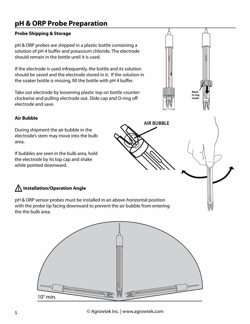
pH & ORP Probe PreparationProbe Shipping & Storage
pH & ORP probes are shipped in a plastic bottle containing a solution of pH 4 buffer and potassium chloride. The electrode should remain in the bottle until it is used.
If the electrode is used infrequently, the bottle and its solution should be saved and the electrode stored in it. If the solution in the soaker bottle is missing, fill the bottle with pH 4 buffer.
Take out electrode by loosening plastic top on bottle counter-clockwise and pulling electrode out. Slide cap and O-ring off electrode and save.
BLACK O-RING
INSIDE TOP
Black O-ring inside
Air Bubble
During shipment the air bubble in the electrode’s stem may move into the bulb area.
If bubbles are seen in the bulb area, hold the electrode by its top cap and shake while pointed downward.
ELB BUB RIAAIR BUBBLE
Installation/Operation Angle
pH & ORP sensor probes must be installed in an above-horizontal position with the probe tip facing downward to prevent the air bubble from entering the the bulb area.
10° min.
6 © Agrowtek Inc. | www.agrowtek.com
Agrowtek Cross-Over
Adapter
cat5 cat5
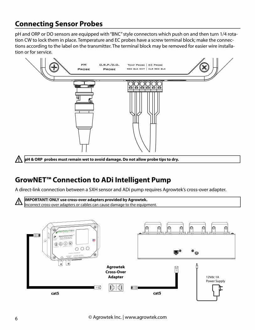
GrowNET™ Connection to ADi Intelligent PumpA direct-link connection between a SXH sensor and ADi pump requires Agrowtek’s cross-over adapter.
IMPORTANT! ONLY use cross-over adapters provided by Agrowtek. Incorrect cross-over adapters or cables can cause damage to the equipment.
12Vdc 1APower Supply
Technology to Help You GrowAGROWtEK
U.S.A.
MADE IN
© Arowtek Inc. | www.agrowtek.com
GrowNET
Link PortMODBUS
TM Digital Water Sensor
Logger & Controller
TEMPERATURECONDUCTIVITY
pHO.R.P. / D.O.
GrowControlTM
pH
Probe
o.r.p./d.o.
Probe
Temp Probe | EC Probe
red blk wht | clr red blk
pH and ORP or DO sensors are equipped with “BNC” style connectors which push on and then turn 1/4 rota-tion CW to lock them in place. Temperature and EC probes have a screw terminal block; make the connec-tions according to the label on the transmitter. The terminal block may be removed for easier wire installa-tion or for service.
Connecting Sensor Probes
pHProbe
o.r.p./d.o.Probe
Temp Probe | EC Probe
red blk wht | clr red blk
pH & ORP probes must remain wet to avoid damage. Do not allow probe tips to dry.
7 © Agrowtek Inc. | www.agrowtek.com
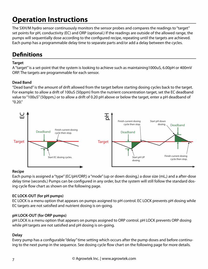
TargetA “target” is a set-point that the system is looking to achieve such as maintaining1000uS, 6.00pH or 400mV ORP. The targets are programmable for each sensor.
Dead Band“Dead band” is the amount of drift allowed from the target before starting dosing cycles back to the target. For example: to allow a drift of 100uS (50ppm) from the nutrient concentration target, set the EC deadband value to “100uS” (50ppm,) or to allow a drift of 0.20 pH above or below the target, enter a pH deadband of “0.20.”
Operation Instructions
Definitions
The SXH/M hydro sensor continuously monitors the sensor probes and compares the readings to “target” set points for pH, conductivity (EC) and ORP (optional.) If the readings are outside of the allowed range, the pumps will sequentially dose according to the configured recipe, repeating until the targets are achieved. Each pump has a programmable delay time to separate parts and/or add a delay between the cycles.
RecipeEach pump is assigned a “type” (EC/pH/ORP,) a “mode” (up or down dosing,) a dose size (mL,) and a after-dose delay time (seconds.) Pumps can be configured in any order, but the system will still follow the standard dos-ing cycle flow chart as shown on the following page.
EC LOCK-OUT (for pH pumps)EC LOCK is a menu option that appears on pumps assigned to pH control. EC LOCK prevents pH dosing while EC targets are not satisfied and nutrient dosing is on-going.
pH LOCK-OUT (for ORP pumps)pH LOCK is a menu option that appears on pumps assigned to ORP control. pH LOCK prevents ORP dosing while pH targets are not satisfied and pH dosing is on-going.
DelayEvery pump has a configurable “delay” time setting which occurs after the pump doses and before continu-ing to the next pump in the sequence. See dosing cycle flow chart on the following page for more details.
EC
Target
Deadband
pH
Target
Deadband
Start EC dosing cycles.
Finish current dosingcycle then stop.
Deadband
Start pH UPdosing.
Finish current dosingcycle then stop.
Start pH downdosing.
Finish current dosingcycle then stop.

8 © Agrowtek Inc. | www.agrowtek.com
Dosing CyclesEC DosingThe system begins by checking the EC against the target set point. If the sensor reading is outside of the target range, the pump will begin a nutrient dosing cycle. The cycle starts by checking the first (left most) pump to see if it is assigned to nutrient control (EC mode.) If it is, the pump’s recipe volume is dosed fol-lowed by a pause for the pump delay time if one is set. The system then progresses to the next pump and continues to dose each remaining “EC pump” before proceeding to check the pH.
pH & ORP DosingThe system then checks the pH value to see if it is with the target range. If the pH requires adjustment, each pump is checked (starting with the first) if it is assigned to pH (up or down) and if so, the recipie dose is ad-ministered. Once all the pumps are checked for pH dosing, if equipped, ORP follows in the same fashion. pH or ORP dosing may be paused if the EC or pH locks are set respectively.
EC LOCK option prevents pH dosing from starting while EC is not in the target range.pH LOCK option prevents ORP from dosing while pH is not in the target range.
Pump # inEC Mode?
CheckEC Target
EC is Low (or High)
More Pumps?
Yes
Run Pump # formL per Recipe
Wait PumpDelay Time
CheckpH Target
pH is High or Low
EC LOCKActivated?
No
Pump # inpH Up/Down
Mode?
Yes
EC is OK pH is OK
Run Pump # formL per Recipe
CheckORP Target
ORP is High or Low
ORP is OK
Yes
No
No
More Pumps?
Wait PumpDelay Time
Yes
No
Yes pH LOCKActivated?
No
Pump # inORP Up/Down
Mode?
Yes
Run Pump # formL per Recipe
More Pumps?
Wait PumpDelay Time
Yes
No
START
No
Yes
No
Start at Pump 1 Start at Pump 1 Start at Pump 1

9 © Agrowtek Inc. | www.agrowtek.com
3-button/LCD display interface allows easy monitoring of sensor values.
Simple menu driven setup for config-uring pump recipes, system settings, sensor calibration and more.
The main screen displays the real-time sensor readings from the at-tached sensors.
Each button is labeled at the bottom of the display to describe it’s function on the current screen or menu.
Controller Operation, Sensors
Simple minimum and maximum recorded values are stored until the user resets the values to the current readings. To view the minimum and maximum values since the last reset, press the button labeled H/L.
To clear the min/max history, press the RST button to reset. The min and max values will all be set to the current readings and will update with higher or lower readings as they occur.
High / Low HistoryGPH MNUH/L
72.06.101550600
°FpHuS
mV
RSTEXIT
72.04.85657480
°FpH
mV
68.44.21551404
HIGHLOW
uS
Technology to Help You GrowAGROWtEK
U.S.A.
MADE IN
© Arowtek Inc. | www.agrowtek.com
GrowNETLink PortMODBUS
TM Digital Water SensorLogger & Controller
TEMPERATURE CONDUCTIVITYpH O.R.P. / D.O.
GrowControlTM
pHProbe
o.r.p./d.o.Probe
Temp Probe | EC Probe
red blk wht | clr red blk
GPH MNUH/L
72.06.21550
°FpHuS
The display can graph the most recent 120 data points from the sensor’s internal data point memory. With the default logging interval of 60 seconds, the graph displays the last two hours of data.
The sensor value is plotted in green. Tem-perature, if overlaid on the plot, is red. Alarm levels as set by the user are plotted in yellow. Pressing the RFH button refreshes the data and replots the graph.
Graphing
RFH BCK
PH
High Alarm
Low Alarm
Temperature
Sensor Data (pH)
GPH MNUH/L
72.06.101550600
°FpHuS
mV
DWN ENTUP
BACKTEMPERATUREPHCOND
GRAPH
ORP
10 © Agrowtek Inc. | www.agrowtek.com
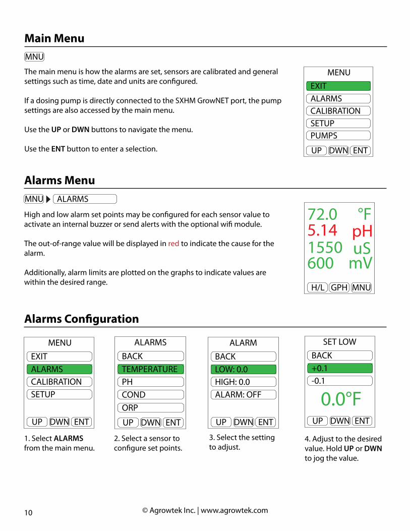
The main menu is how the alarms are set, sensors are calibrated and general settings such as time, date and units are configured.
If a dosing pump is directly connected to the SXHM GrowNET port, the pump settings are also accessed by the main menu.
Use the UP or DWN buttons to navigate the menu.
Use the ENT button to enter a selection.
Main MenuGPH MNUH/L
72.06.101550600
°FpHuS
mV
High and low alarm set points may be configured for each sensor value to activate an internal buzzer or send alerts with the optional wifi module.
The out-of-range value will be displayed in red to indicate the cause for the alarm.
Additionally, alarm limits are plotted on the graphs to indicate values are within the desired range.
Alarms Menu
DWN ENTUP
EXITALARMSCALIBRATIONSETUPPUMPS
MENU
GPH MNUH/L
72.06.101550600
°FpHuS
mV
DWN ENTUP
EXITALARMSCALIBRATIONSETUPPUMPS
MENU
DWN ENTUP
EXITALARMSCALIBRATIONSETUP
MENU
DWN ENTUP
BACK+0.1-0.1
SET LOW
0.0°F
1. Select ALARMS from the main menu.
3. Select the setting to adjust.
2. Select a sensor to configure set points.
4. Adjust to the desired value. Hold UP or DWN to jog the value.
DWN ENTUP
BACKLOW: 0.0HIGH: 0.0ALARM: OFF
ALARM
DWN ENTUP
BACKTEMPERATUREPHCOND
ALARMS
ORP
Alarms Configuration
GPH MNUH/L
72.05.141550600
°FpHuS
mV
11 © Agrowtek Inc. | www.agrowtek.com
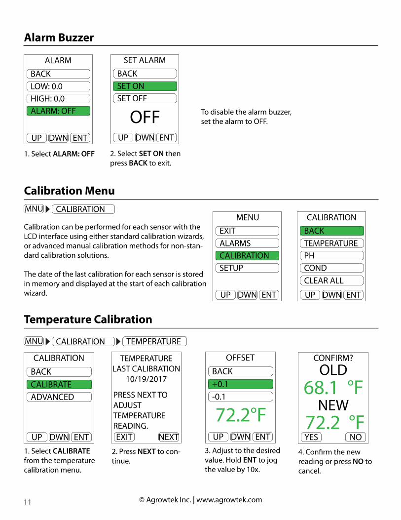
To disable the alarm buzzer, set the alarm to OFF.
Calibration Menu
Calibration can be performed for each sensor with the LCD interface using either standard calibration wizards, or advanced manual calibration methods for non-stan-dard calibration solutions.
The date of the last calibration for each sensor is stored in memory and displayed at the start of each calibration wizard.
GPH MNUH/L
72.06.101550600
°FpHuS
mV
DWN ENTUP
EXITALARMSCALIBRATIONSETUPPUMPS
MENU
DWN ENTUP
EXITALARMSCALIBRATIONSETUP
MENU
DWN ENTUP
BACKTEMPERATUREPHCOND
CALIBRATION
CLEAR ALL
DWN ENTUP
BACKLOW: 0.0HIGH: 0.0ALARM: OFF
ALARM
1. Select ALARM: OFF
DWN ENTUP
BACKSET ONSET OFF
SET ALARM
OFF
2. Select SET ON then press BACK to exit.
Alarm Buzzer
1. Select CALIBRATE from the temperature calibration menu.
3. Adjust to the desired value. Hold ENT to jog the value by 10x.
2. Press NEXT to con-tinue.
4. Confirm the new reading or press NO to cancel.
DWN ENTUP
BACK+0.1-0.1
OFFSET
72.2°FNEXTEXIT
TEMPERATURELAST CALIBRATION
10/19/2017
PRESS NEXT TOADJUSTTEMPERATUREREADING.
NOYES
CONFIRM?
72.2 °F
68.1 °FOLD
NEW
DWN ENTUP
BACKCALIBRATEADVANCED
CALIBRATION
GPH MNUH/L
72.06.101550600
°FpHuS
mV
DWN ENTUP
EXITALARMSCALIBRATIONSETUPPUMPS
MENU
Temperature Calibration
DWN ENTUP
BACKTEMPERATUREPHCOND
CALIBRATION
DO
12 © Agrowtek Inc. | www.agrowtek.com
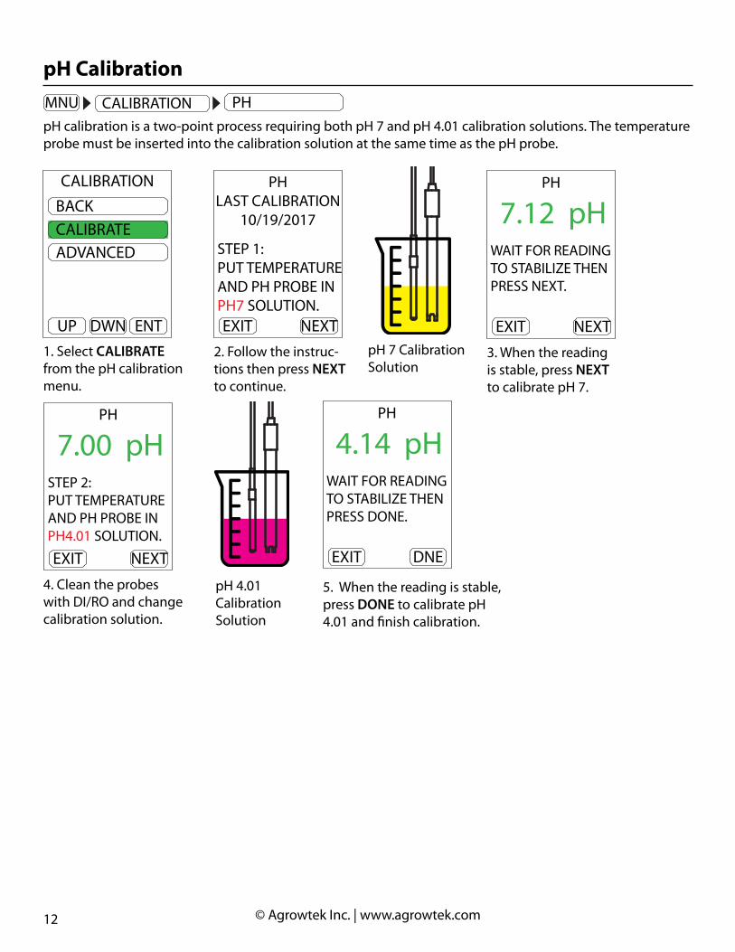
pH calibration is a two-point process requiring both pH 7 and pH 4.01 calibration solutions. The temperature probe must be inserted into the calibration solution at the same time as the pH probe.
GPH MNUH/L
72.06.101550600
°FpHuS
mV
DWN ENTUP
EXITALARMSCALIBRATIONSETUPPUMPS
MENU
pH Calibration
2. Follow the instruc-tions then press NEXT to continue.
4. Clean the probes with DI/RO and change calibration solution.
3. When the reading is stable, press NEXT to calibrate pH 7.
5. When the reading is stable, press DONE to calibrate pH 4.01 and finish calibration.
NEXTEXIT
PHLAST CALIBRATION
10/19/2017
STEP 1:PUT TEMPERATUREAND PH PROBE INPH7 SOLUTION.
NEXTEXIT
PH
WAIT FOR READINGTO STABILIZE THENPRESS NEXT.
7.12 pH
NEXTEXIT
PH
STEP 2:PUT TEMPERATUREAND PH PROBE INPH4.01 SOLUTION.
7.00 pH
DNEEXIT
PH
WAIT FOR READINGTO STABILIZE THENPRESS DONE.
4.14 pH
pH 7 Calibration Solution
pH 4.01 Calibration Solution
1. Select CALIBRATE from the pH calibration menu.
DWN ENTUP
BACKCALIBRATEADVANCED
CALIBRATION DWN ENTUP
BACKTEMPERATUREPHCOND
CALIBRATION
DO

13 © Agrowtek Inc. | www.agrowtek.com
1. Select CALIBRATE from the conductivity calibration menu.
3. When the reading is stable, press DONE to complete the calibration.
2. Follow the instruc-tions then press NEXT to continue.
DWN ENTUP
BACKCALIBRATEADVANCED
CALIBRATION
GPH MNUH/L
72.06.101550600
°FpHuS
mV
DWN ENTUP
EXITALARMSCALIBRATIONSETUPPUMPS
MENU
Conductivity Calibration
Conductivity calibration is a single point process requiring 1413 uS calibration solution. The temperature probe must be inserted into the calibration solution at the same time as the conductivity probe.
NEXTEXIT
CONDUCTIVITYLAST CALIBRATION
10/19/2017
PUT TEMPERATUREAND EC PROBE IN1413uS SOLUTION.
1. Select CALIBRATE from the conductivity calibration menu.
3. When the reading is stable, press DONE to complete the calibration.
2. Follow the instruc-tions then press NEXT to continue.
DWN ENTUP
BACKCALIBRATEADVANCED
CALIBRATION
GPH MNUH/L
72.06.101550600
°FpHuS
mV
DWN ENTUP
EXITALARMSCALIBRATIONSETUPPUMPS
MENU
O.R.P. Calibration
ORP (optional) calibration is a single point process requiring 470 mV calibration solution.
NEXTEXIT
ORPLAST CALIBRATION
10/19/2017
PUT ORP PROBE IN470mV SOLUTION.
DNEEXIT
CONDUCTIVITY
WAIT FOR READINGTO STABILIZE THENPRESS DONE.
1440 uS
DWN ENTUP
BACKTIME/DATEUNITSLOG INTERVAL
SETUP
NEXT
DNEEXIT
CONDUCTIVITY
WAIT FOR READINGTO STABILIZE THENPRESS DONE.
1440 uS
DWN ENTUP
BACKTEMPERATUREPHCOND
CALIBRATION
DO
DWN ENTUP
BACKORPCLEAR ALL
CALIBRATION

14 © Agrowtek Inc. | www.agrowtek.com
1. Select CLEAR ALL from the calibration menu.
2. Press YES to restore factory calibration.
GPH MNUH/L
72.06.101550600
°FpHuS
mV
DWN ENTUP
EXITALARMSCALIBRATIONSETUPPUMPS
MENU
Clear Calibration
Calibration can be restored to factory defaults by selecting CLEAR ALL.
NOYES
RESTORE TOFACTORY
CALIBRATION?
DWN ENTUP
BACKTIME/DATEUNITSLOG INTERVAL
SETUP
NEXT
DWN ENTUP
BACKTEMPERATUREPHCOND
CALIBRATION
CLEAR ALL

15 © Agrowtek Inc. | www.agrowtek.com
Advanced CalibrationSensors values may be manually calibrated to alternate standards using the advance calibration features.
OFFSET calibration applies a linear offset adjustment to the value. SPAN calibration applies an adjustment to the slope of the sensor value.
Note: pH and conductivty are temperature compensated (ATC) sensors. For accurate calibration, the temperature probe must be in the pH and conduc-tivity calibration standards. Allow all readings to stabilize before performing an offset or span calibration operation.
PHCAL 7 sets the pH 7 calibration (offset.) Cal 7 automatically clears span calibration point prior performing pH 7 calibration.
SPAN calibration is performed typically at pH 4.01 or 10.0 (Always perform pH 7 calibration first.)
CONDUCTIVITYSET CAL 0 calibrates a dry EC probe if required. (not recommended)SPAN calibration is recommended at 1413uS. If using ppm standards, ensure the display is in the correct units.
DiSSOLVED OXYGEN (D.O.)OFFSET calibration is recommended in zero oxygen solution.SPAN calibration is recommended at a known DO level or in air.
OXIDATION REDUCTION POTENTIAL (O.R.P.)OFFSET is recommended at 270mVSPAN is recommended at 470mV
DWN ENTUP
BACKCALIBRATEADVANCED
CALIBRATION
4-20mA analog outputs may also be calibrated with a positive or negative offset to compensate for variation in DAC’s/ADC’s. The sensors’ current output may be incrementally increased or decreased in steps of 0.005mA over a range of +/-2mA.
1 Offset bit = 0.005mA, Range = +/-400 bits (+/-2mA)
This calibration procedure is optional and only for use with custom PLC appli-cations.
1. Observe the PLC’s input or data readings.2. Increase or decrease the offset value to incremenetally adjust the current output until the values match.
Analog Output Calibration
DWN ENTUP
BACK+1-1
ANALOG
-5
16 © Agrowtek Inc. | www.agrowtek.com
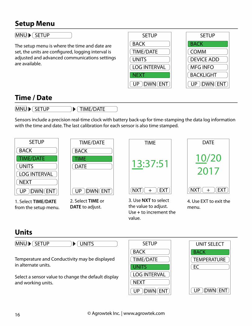
The setup menu is where the time and date are set, the units are configured, logging interval is adjusted and advanced communications settings are available.
Setup Menu
Sensors include a precision real-time clock with battery back-up for time-stamping the data log information with the time and date. The last calibration for each sensor is also time stamped.
Time / Date
1. Select TIME/DATE from the setup menu.
3. Use NXT to select the value to adjust. Use + to increment the value.
2. Select TIME or DATE to adjust.
4. Use EXT to exit the menu.
DWN ENTUP
BACKTIME/DATEUNITSLOG INTERVAL
SETUP
NEXT
DWN ENTUP
BACKCOMMDEVICE ADDMFG INFO
SETUP
BACKLIGHT
DWN ENTUP
BACKTIME/DATEUNITSLOG INTERVAL
SETUP
NEXT
DWN ENTUP
BACKTIMEDATE
TIME/DATE
+ EXTNXT
DATE
10/202017
+ EXTNXT
TIME
13:37:51
Temperature and Conductivity may be displayed in alternate units.
Select a sensor value to change the default display and working units.
Units
DWN ENTUP
BACKTIME/DATEUNITSLOG INTERVAL
SETUP
NEXTDWN ENTUP
BACKTEMPERATUREEC
UNIT SELECT
GPH MNUH/L
72.06.101550600
°FpHuS
mV
DWN ENTUP
EXITALARMSCALIBRATIONSETUPPUMPS
MENU
GPH MNUH/L
72.06.101550600
°FpHuS
mV
DWN ENTUP
EXITALARMSCALIBRATIONSETUPPUMPS
MENU
DWN ENTUP
BACKTIME/DATEUNITSLOG INTERVAL
SETUP
NEXT
GPH MNUH/L
72.06.101550600
°FpHuS
mV
DWN ENTUP
EXITALARMSCALIBRATIONSETUPPUMPS
MENU
DWN ENTUP
BACKTIME/DATEUNITSLOG INTERVAL
SETUP
NEXT

17 © Agrowtek Inc. | www.agrowtek.com
Adjust the interval for recording data points in the on-board memort. Acceptable values are from 1 - 65535 seconds.
21,600 data points can be stored for each sensor value. The most recent 120 data points are shown on the graphical history.
The entire data history may be downloaded from the sensor to a .csv file with the LX1 USB AgrowLINK and free software.
Note: 60 second intervals = 15 days of data storage.
Logging Interval
Configure temperature units:
1. Select TEMPERATURE from the units menu.
2. Select the desired units and press ENT.
DWN ENTUP
BACKTEMPERATUREEC
UNIT SELECTTemperature may be displayed in °F or °C.
Note: Check alarm settings when converting temperature units.
DWN ENTUP
BACK°C°F
UNIT SELECT
68.0°F
Configure conductivity units:
1. Select EC from the units menu.
2. Select the desired units and press ENT.
Conductivity may be displayed in default units of microSiemens (uS) or total dissolved solids in parts per million (ppm.)
The TDS conversion factor used by this meter is 500.
TDSppm = uS x 0.5
DWN ENTUP
BACKTEMPERATUREEC
UNIT SELECT
DWN ENTUP
BACKUSTDS
UNIT SELECT
654 ppm
GPH MNUH/L
72.06.101550600
°FpHuS
mV
DWN ENTUP
EXITALARMSCALIBRATIONSETUPPUMPS
MENU
DWN ENTUP
BACKTIME/DATEUNITSLOG INTERVAL
SETUP
NEXT
1. Select LOG INTERVAL from the setup menu.
2. Adjust the value then select BACK.
DWN ENTUP
BACKTIME/DATEUNITSLOG INTERVAL
SETUP
NEXT
DWN ENTUP
BACK+1-1
LOGGIN INTERVAL
60 SEC
18 © Agrowtek Inc. | www.agrowtek.com
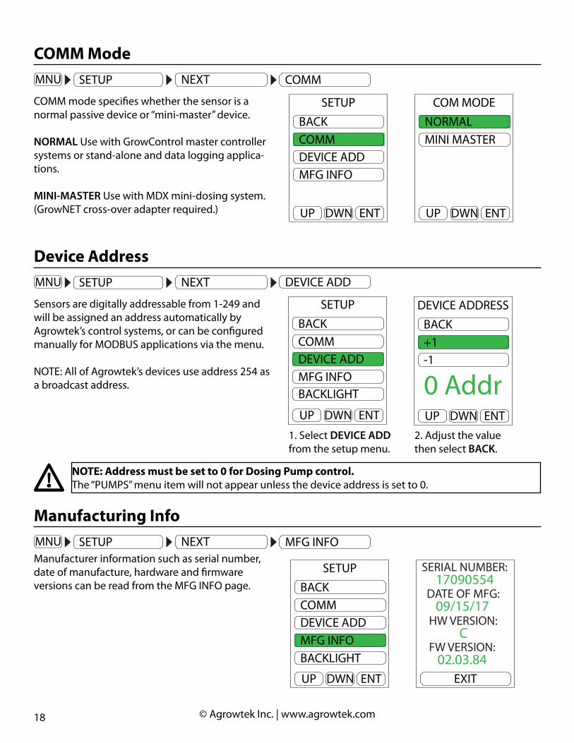
COMM mode specifies whether the sensor is a normal passive device or “mini-master” device.
NORMAL Use with GrowControl master controller systems or stand-alone and data logging applica-tions.
MINI-MASTER Use with MDX mini-dosing system. (GrowNET cross-over adapter required.)
COMM ModeGPH MNUH/L
72.06.101550600
°FpHuS
mV
DWN ENTUP
EXITALARMSCALIBRATIONSETUPPUMPS
MENU
DWN ENTUP
BACKTIME/DATEUNITSLOG INTERVAL
SETUP
NEXT
DWN ENTUP
BACKCOMMDEVICE ADDMFG INFO
SETUP
BACKLIGHT
Sensors are digitally addressable from 1-249 and will be assigned an address automatically by Agrowtek’s control systems, or can be configured manually for MODBUS applications via the menu.
NOTE: All of Agrowtek’s devices use address 254 as a broadcast address.
Device Address
NOTE: Address must be set to 0 for Dosing Pump control.The “PUMPS” menu item will not appear unless the device address is set to 0.
GPH MNUH/L
72.06.101550600
°FpHuS
mV
DWN ENTUP
EXITALARMSCALIBRATIONSETUPPUMPS
MENU
DWN ENTUP
BACKTIME/DATEUNITSLOG INTERVAL
SETUP
NEXT
DWN ENTUP
BACKCOMMDEVICE ADDMFG INFO
SETUP
BACKLIGHT
1. Select DEVICE ADD from the setup menu.
2. Adjust the value then select BACK.
DWN ENTUP
BACKCOMMDEVICE ADDMFG INFO
SETUP
BACKLIGHT
DWN ENTUP
BACK+1-1
DEVICE ADDRESS
0 Addr
DWN ENTUP
BACKCOMMDEVICE ADDMFG INFO
SETUP
DWN ENTUP
NORMALMINI MASTER
COM MODE
Manufacturing InfoGPH MNUH/L
72.06.101550600
°FpHuS
mV
DWN ENTUP
EXITALARMSCALIBRATIONSETUPPUMPS
MENU
DWN ENTUP
BACKTIME/DATEUNITSLOG INTERVAL
SETUP
NEXT
DWN ENTUP
BACKCOMMDEVICE ADDMFG INFO
SETUP
BACKLIGHTManufacturer information such as serial number, date of manufacture, hardware and firmware versions can be read from the MFG INFO page.
DWN ENTUP
BACKCOMMDEVICE ADDMFG INFO
SETUP
BACKLIGHT
EXIT
17090554SERIAL NUMBER:
09/15/17DATE OF MFG:
CHW VERSION:
02.03.84FW VERSION:

19 © Agrowtek Inc. | www.agrowtek.com
Display Back Light TimerGPH MNUH/L
72.06.101550600
°FpHuS
mV
DWN ENTUP
EXITALARMSCALIBRATIONSETUPPUMPS
MENU
DWN ENTUP
BACKTIME/DATEUNITSLOG INTERVAL
SETUP
NEXT
DWN ENTUP
BACKCOMMDEVICE ADDMFG INFO
SETUP
BACKLIGHTThe display back light can be programmed to turn off after a specified time of inactivity from the last time a button is pressed.
The delay can be set from 1-255 minutes, or set to 0 to disable the back light timer and keep the display on continuously.
DWN ENTUP
BACKCOMMDEVICE ADDMFG INFO
SETUP
BACKLIGHT
DWN ENTUP
BACK+1-1
BACKLIGHT
60 Min

20 © Agrowtek Inc. | www.agrowtek.com
Dosing Pump Control Menu
The “Pumps” menu item will not appear unless the communication mode is set to “MINI-MASTER” and the device address is set to “0” (see COMM MODE and DEVICE ADDRESS.)
GPH MNUH/L
72.06.101550600
°FpHuS
mV
DWN ENTUP
EXITALARMSCALIBRATIONSETUPPUMPS
MENU
The PUMPS menu is displayed when the hydro sensor is connected to a dosing pump and contains all of the configuration, target and recipe settings pages for controlling the pumps.
DWN ENTUP
EXITALARMSCALIBRATIONSETUPPUMPS
MENU
DWN ENTUP
BACKRUN/STOPRECIPETARGETS
PUMPS
PRIME
Pumps may be manually operated to prime the lines or for other maintenance reasons. From the Prime menu, select a pump to prime. Pumps may be operated in the forward or reverse direction.
PrimingGPH MNUH/L
72.06.101550600
°FpHuS
mV
DWN ENTUP
EXITALARMSCALIBRATIONSETUPPUMPS
MENU
DWN ENTUP
BACKCONFIGUREPRIME
PUMPS
2. Choose a pump to operate.
DWN ENTUP
BACKPUMP 1PUMP 2PUMP 3PUMP 4
PRIME
1. Select NEXT from the PUMPS menu.
DWN ENTUP
BACKRUN/STOPRECIPETARGETS
PUMPS
PRIME
3. Select a direction and HOLD the ENT button. Re-lease the button to stop.
DWN ENTUP
BACKFORWARDREVERSE
PUMP 1
Controller Operation, PumpsMDX dosing systems have a “PUMPS” menu for configuring the control settings for peristaltic pumps.

21 © Agrowtek Inc. | www.agrowtek.com
Recipe MenuGPH MNUH/L
72.06.101550600
°FpHuS
mV
Each pump is configured with a “recipe” containing the pump mode (EC or pH) and dose volume (mL.)
MDX systems are available with 1, 2 or 4 dosing pump heads and each may be configured for EC or pH con-trol in any order or combination.
NOTE: Dosing will occur from the lowest to the highest numbered pump when more than one pump is in the same mode (EC, pH-UP or PH-DOWN.)
Select a pump number to configure the recipe settings as described below.
2. Select RECIPE to con-figure the pump parts.
3. Select a pump to configure the its mode and dose size.
DWN ENTUP
BACKRUN/STOPRECIPETARGETS
PUMPS
PRIME
DWN ENTUP
BACKPUMP 1PUMP 2PUMP 3PUMP 4
RECIPE
DWN ENTUP
EXITALARMSCALIBRATIONSETUPPUMPS
MENU
DWN ENTUP
BACKRUN/STOPRECIPETARGETS
PUMPS
NEXT
DWN ENTUP
EXITALARMSCALIBRATIONSETUPPUMPS
MENU
1. Select PUMPS to configure the pumps.
The dosing pumps must be placed into RUN mode for autonomous dosing to take place. The dosing pumps may be immediately disabled to stop a dosing operation due to an error, nutrient outage, or maintenance requirement. To stop all dosing pumps and prevent autonomous operation, place the pump into STOP mode.
Run/Stop
GPH MNUH/L
72.06.101550600
°FpHuS
mV
DWN ENTUP
EXITALARMSCALIBRATIONSETUPPUMPS
MENU
DWN ENTUP
BACKRUN/STOPRECIPETARGETS
PUMPS
NEXT
The RUN/STOP menu enables or disables the pumps
Select STOP to disable the pumps from running automatically and to abort any current operation.
Select RUN to allow the pumps to operate based on your settings.
DWN ENTUP
BACKRUN/STOPRECIPETARGETS
PUMPS
PRIME
DWN ENTUP
RUNSTOP
RUN/STOP
DWN ENTUP
RUNSTOP
RUN/STOP
22 © Agrowtek Inc. | www.agrowtek.com
Pump Mode
GPH MNUH/L
72.06.101550600
°FpHuS
mV
DWN ENTUP
EXITALARMSCALIBRATIONSETUPPUMPS
MENU
DWN ENTUP
BACKRUN/STOPRECIPETARGETS
PUMPS
NEXT
DWN ENTUP
BACKPUMP 1PUMP 2PUMP 3PUMP 4
RECIPE
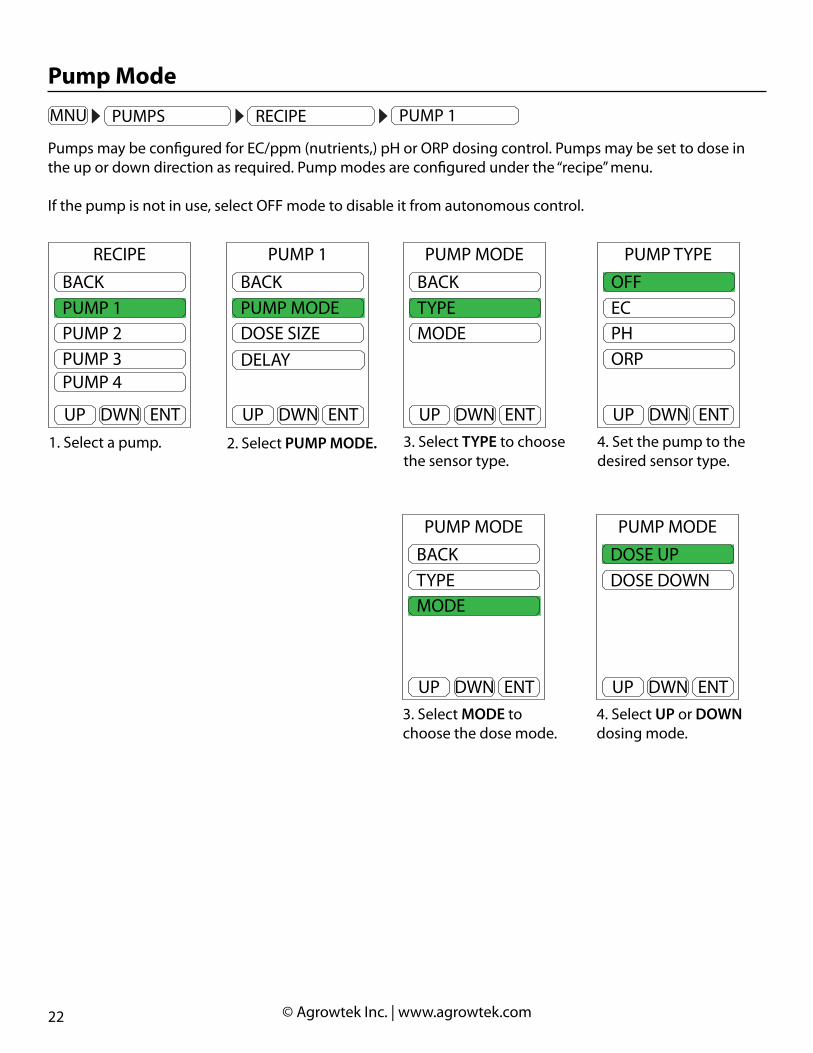
Pumps may be configured for EC/ppm (nutrients,) pH or ORP dosing control. Pumps may be set to dose in the up or down direction as required. Pump modes are configured under the “recipe” menu.
If the pump is not in use, select OFF mode to disable it from autonomous control.
1. Select a pump. 3. Select TYPE to choose the sensor type.
2. Select PUMP MODE.
DWN ENTUP
BACKPUMP 1PUMP 2PUMP 3PUMP 4
RECIPE
DWN ENTUP
BACKPUMP MODEDOSE SIZE
PUMP 1
DELAY
DWN ENTUP
BACKTYPEMODE
PUMP MODE
4. Set the pump to the desired sensor type.
DWN ENTUP
OFFECPHORP
PUMP TYPE
3. Select MODE to choose the dose mode.
DWN ENTUP
BACKTYPEMODE
PUMP MODE
4. Select UP or DOWN dosing mode.
DWN ENTUP
DOSE UPDOSE DOWN
PUMP MODE
23 © Agrowtek Inc. | www.agrowtek.com
Dose Size
GPH MNUH/L
72.06.101550600
°FpHuS
mV
DWN ENTUP
EXITALARMSCALIBRATIONSETUPPUMPS
MENU
DWN ENTUP
BACKRUN/STOPRECIPETARGETS
PUMPS
NEXT
DWN ENTUP
BACKPUMP 1PUMP 2PUMP 3PUMP 4
RECIPE
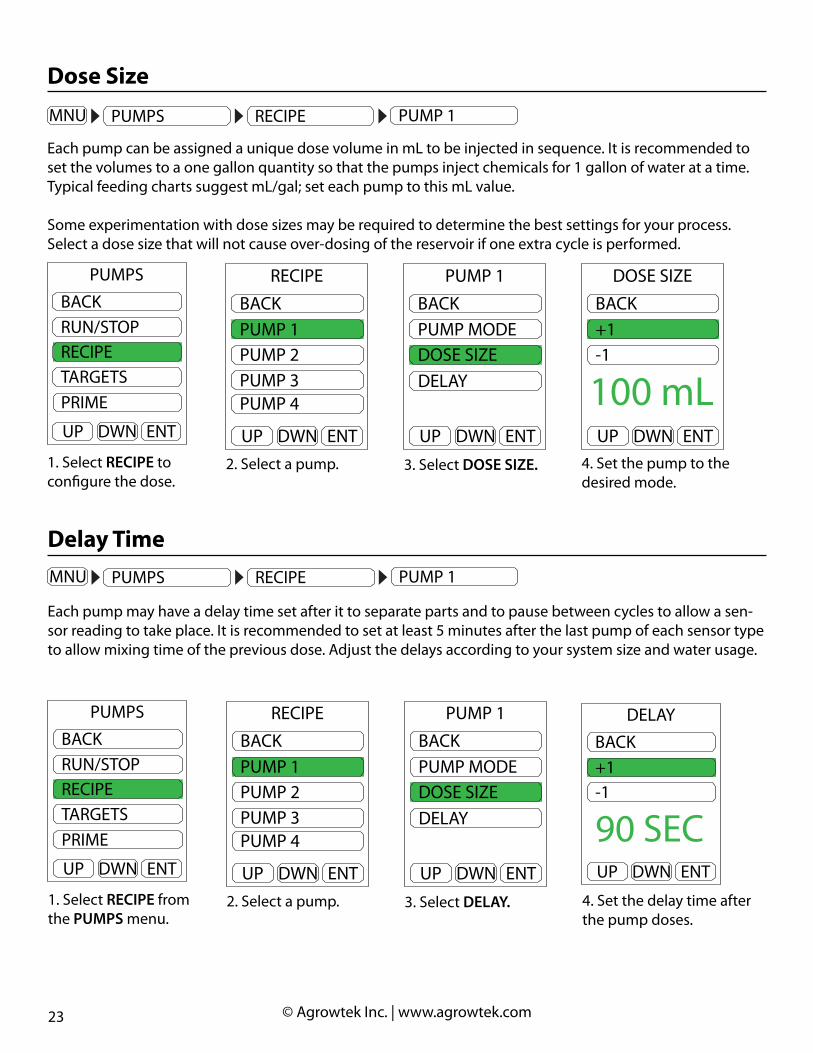
Each pump can be assigned a unique dose volume in mL to be injected in sequence. It is recommended to set the volumes to a one gallon quantity so that the pumps inject chemicals for 1 gallon of water at a time. Typical feeding charts suggest mL/gal; set each pump to this mL value.
Some experimentation with dose sizes may be required to determine the best settings for your process. Select a dose size that will not cause over-dosing of the reservoir if one extra cycle is performed.
2. Select a pump. 4. Set the pump to the desired mode.
3. Select DOSE SIZE.
DWN ENTUP
BACKPUMP 1PUMP 2PUMP 3PUMP 4
RECIPE
DWN ENTUP
BACKPUMP MODEDOSE SIZE
PUMP 1
DELAY
DWN ENTUP
BACK+1-1
DOSE SIZE
100 mL
1. Select RECIPE to configure the dose.
DWN ENTUP
BACKRUN/STOPRECIPETARGETS
PUMPS
PRIME
Delay TimeGPH MNUH/L
72.06.101550600
°FpHuS
mV
DWN ENTUP
EXITALARMSCALIBRATIONSETUPPUMPS
MENU
Each pump may have a delay time set after it to separate parts and to pause between cycles to allow a sen-sor reading to take place. It is recommended to set at least 5 minutes after the last pump of each sensor type to allow mixing time of the previous dose. Adjust the delays according to your system size and water usage.
DWN ENTUP
BACK+1-1
DELAY
90 SEC
DWN ENTUP
BACKRUN/STOPRECIPETARGETS
PUMPS
NEXT
DWN ENTUP
BACKPUMP 1PUMP 2PUMP 3PUMP 4
RECIPE
2. Select a pump. 4. Set the delay time after the pump doses.
3. Select DELAY.
DWN ENTUP
BACKPUMP 1PUMP 2PUMP 3PUMP 4
RECIPE
DWN ENTUP
BACKPUMP MODEDOSE SIZE
PUMP 1
DELAY
1. Select RECIPE from the PUMPS menu.
DWN ENTUP
BACKRUN/STOPRECIPETARGETS
PUMPS
PRIME

24 © Agrowtek Inc. | www.agrowtek.com
EC Lock-Out
GPH MNUH/L
72.06.101550600
°FpHuS
mV
DWN ENTUP
EXITALARMSCALIBRATIONSETUPPUMPS
MENU
DWN ENTUP
BACKRUN/STOPRECIPETARGETS
PUMPS
NEXT
DWN ENTUP
BACKPUMP 1PUMP 2PUMP 3PUMP 4
RECIPE
If PUMP TYPE is set to PH, the EC LOCK option will appear in the recipe menu for that pump. If the lock is set to “ON” the system will lock-out this pump until EC dosing has completed.
Set the EC LOCK to ON to only allow the pH pump to operate after EC dosing has reached the target.Set the EC LOCK to OFF to allow a pH dosing cycle after each EC dosing cycle (as required.)
2. Select a pump. 4. Set the pump to the desired mode.
3. Select EC LOCK.
DWN ENTUP
BACKPUMP 1PUMP 2PUMP 3PUMP 4
RECIPE
DWN ENTUP
BACKPUMP MODEDOSE SIZE
PUMP 1
EC LOCKDELAY
DWN ENTUP
BACKLOCKUNLOCK
EC LOCK
ONDWN ENTUP
EXITALARMSCALIBRATIONSETUPPUMPS
MENU
1. Select PUMPS to configure the pumps.
pH Lock-Out
GPH MNUH/L
72.06.101550600
°FpHuS
mV
DWN ENTUP
EXITALARMSCALIBRATIONSETUPPUMPS
MENU
DWN ENTUP
BACKRUN/STOPRECIPETARGETS
PUMPS
NEXT
DWN ENTUP
BACKPUMP 1PUMP 2PUMP 3PUMP 4
RECIPE
If PUMP TYPE is set to ORP, the PH LOCK option will appear in the recipe menu for that pump. If the lock is set to “ON” the system will lock-out this pump until pH dosing has completed.
Set the EC LOCK to ON to only allow the ORP pump to operate after pH dosing has reached the target.Set the EC LOCK to OFF to allow a ORP dosing cycle after each pH dosing cycle (as required.)
2. Select a pump. 4. Set the pump to the desired mode.
3. Select EC LOCK.
DWN ENTUP
BACKPUMP 1PUMP 2PUMP 3PUMP 4
RECIPE
DWN ENTUP
BACKPUMP MODEDOSE SIZE
PUMP 1
PH LOCKDELAY
DWN ENTUP
BACKLOCKUNLOCK
EC LOCK
ONDWN ENTUP
EXITALARMSCALIBRATIONSETUPPUMPS
MENU
1. Select PUMPS to configure the pumps.

25 © Agrowtek Inc. | www.agrowtek.com
Target Value
GPH MNUH/L
72.06.101550600
°FpHuS
mV
DWN ENTUP
EXITALARMSCALIBRATIONSETUPPUMPS
MENU
DWN ENTUP
BACKRUN/STOPRECIPETARGETS
PUMPS
NEXT
DWN ENTUP
BACKPUMP 1PUMP 2PUMP 3PUMP 4
RECIPE
The target pH, ORP or EC set point is what the system will attempt to maintain by following the dosing “re-ceipe” settings. Set the desired ideal target values for EC and pH.
2. Select a sensor to setup the target value.
4. Set the target value for the sensor.
3. Select TARGET.
DWN ENTUP
BACKECPH
TARGETS
ORP
DWN ENTUP
BACK+1-1
TARGET
1000 uS
DWN ENTUP
BACKECPH
TARGETS
ORP
DWN ENTUP
BACKTARGETDEADBAND
TARGETS
DWN ENTUP
BACK+0.01-0.01
TARGET
6.00 pHDWN ENTUP
BACKRUN/STOPRECIPETARGETS
PUMPS
PRIME
1. Select TARGETS in the PUMPS menu.
DWN ENTUP
BACKECPH
TARGETS
ORP
DWN ENTUP
BACK+1-1
TARGET
600 mV

26 © Agrowtek Inc. | www.agrowtek.com
1. Select a sensor to set the deadband value.
3. Set the deadband value for the sensor.
2. SelectDEADBAND
DWN ENTUP
BACKECPH
TARGETS
ORP
DWN ENTUP
BACKTARGETDEADBAND
TARGETS
DWN ENTUP
BACK+1-1
DEADBAND
100 uS
DWN ENTUP
BACKECPH
TARGETS
ORP
DWN ENTUP
BACKTARGETDEADBAND
TARGETS
DWN ENTUP
BACK+0.01-0.01
DEADBAND
0.50 pH
Deadband
GPH MNUH/L
72.06.101550600
°FpHuS
mV
DWN ENTUP
EXITALARMSCALIBRATIONSETUPPUMPS
MENU
DWN ENTUP
BACKRUN/STOPRECIPETARGETS
PUMPS
NEXT
DWN ENTUP
BACKPUMP 1PUMP 2PUMP 3PUMP 4
RECIPE
Deadband is the amount of change or drift from the target before the system takes action. Set the dead band for EC and pH with the amount of drift that is allowed by your process requirements.
EC
Target
Deadband
pH
Target
Deadband
Start EC dosing cycles.
Finish current dosingcycle then stop.
Deadband
Start pH UPdosing.
Finish current dosingcycle then stop.
Start pH downdosing.
Finish current dosingcycle then stop.
27 © Agrowtek Inc. | www.agrowtek.com
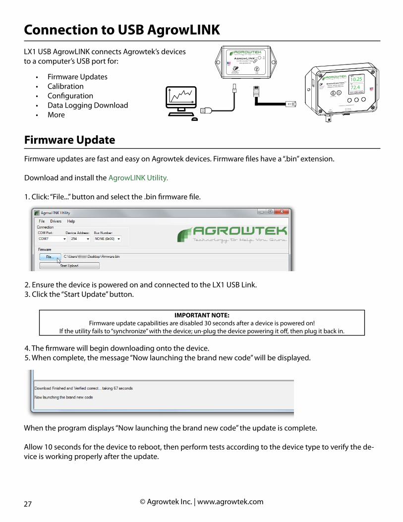
LX1 USB AgrowLINK connects Agrowtek’s devices to a computer’s USB port for:
Connection to USB AgrowLINK
• Firmware Updates• Calibration• Configuration• Data Logging Download• More
Technology to Help You GrowAGROWtEK
U.S.A.
MADE INwww.agrowtek.com
GrowNETDevice/Hub
TM
USB
AgrowLINK TM
LX1 USB to GrowNET™ Bridge
TXRX
Firmware updates are fast and easy on Agrowtek devices. Firmware files have a “.bin” extension.
Download and install the AgrowLINK Utility.
1. Click: “File...” button and select the .bin firmware file.
Firmware Update
2. Ensure the device is powered on and connected to the LX1 USB Link.3. Click the “Start Update” button.
IMPORTANT NOTE:Firmware update capabilities are disabled 30 seconds after a device is powered on!
If the utility fails to “synchronize” with the device; un-plug the device powering it off, then plug it back in.
4. The firmware will begin downloading onto the device.5. When complete, the message “Now launching the brand new code” will be displayed.
When the program displays “Now launching the brand new code” the update is complete.
Allow 10 seconds for the device to reboot, then perform tests according to the device type to verify the de-vice is working properly after the update.
Technology to Help You GrowAGROWtEK
U.S.A.
MADE IN
© Arowtek Inc. | www.agrowtek.com
GrowNET
Link PortMODBUS
TM Digital Water Sensor
Logger & Controller
TEMPERATURE pH
GrowControlTM
pH
Probe
Temp Probe
red blk wht
GPH MNUH/L
10.25pH
72.4°F
28 © Agrowtek Inc. | www.agrowtek.com
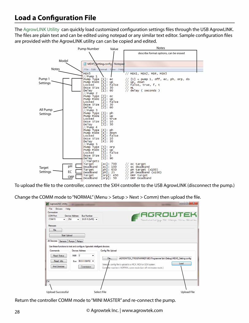
The AgrowLINK Utility can quickly load customized configuration settings files through the USB AgrowLINK.The files are plain text and can be edited using notepad or any similar text editor. Sample configuration files are provided with the AgrowLINK utility can can be copied and edited.
Load a Configuration File
To upload the file to the controller, connect the SXH controller to the USB AgrowLINK (disconnect the pump.)
Change the COMM mode to “NORMAL” (Menu > Setup > Next > Comm) then upload the file.
Select File Upload FileUpload Successful
Return the controller COMM mode to “MINI MASTER” and re-connect the pump.
Pump Number Notesdescribe format options, can be erased
Value
Model
Pump 1Settings
All PumpSettings
pH
ECORP
TargetSettings
Notes
29 © Agrowtek Inc. | www.agrowtek.com
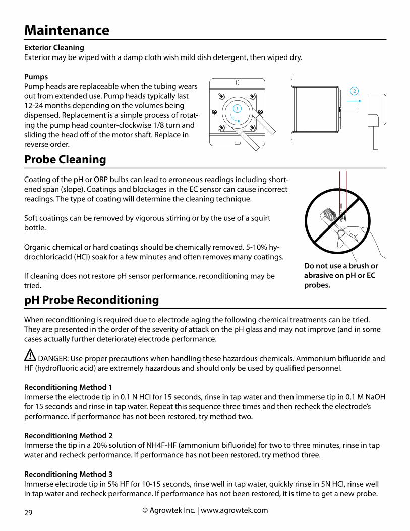
Exterior CleaningExterior may be wiped with a damp cloth wish mild dish detergent, then wiped dry.
PumpsPump heads are replaceable when the tubing wears out from extended use. Pump heads typically last 12-24 months depending on the volumes being dispensed. Replacement is a simple process of rotat-ing the pump head counter-clockwise 1/8 turn and sliding the head off of the motor shaft. Replace in reverse order.
Maintenance
1
2
Probe Cleaning
Coating of the pH or ORP bulbs can lead to erroneous readings including short-ened span (slope). Coatings and blockages in the EC sensor can cause incorrect readings. The type of coating will determine the cleaning technique.
Soft coatings can be removed by vigorous stirring or by the use of a squirt bottle.
Organic chemical or hard coatings should be chemically removed. 5-10% hy-drochloricacid (HCl) soak for a few minutes and often removes many coatings.
If cleaning does not restore pH sensor performance, reconditioning may be tried.
Do not use a brush or abrasive on pH or EC probes.
pH Probe Reconditioning
When reconditioning is required due to electrode aging the following chemical treatments can be tried. They are presented in the order of the severity of attack on the pH glass and may not improve (and in some cases actually further deteriorate) electrode performance.
DANGER: Use proper precautions when handling these hazardous chemicals. Ammonium bifluoride and HF (hydrofluoric acid) are extremely hazardous and should only be used by qualified personnel.
Reconditioning Method 1Immerse the electrode tip in 0.1 N HCl for 15 seconds, rinse in tap water and then immerse tip in 0.1 M NaOH for 15 seconds and rinse in tap water. Repeat this sequence three times and then recheck the electrode’s performance. If performance has not been restored, try method two.
Reconditioning Method 2Immerse the tip in a 20% solution of NH4F-HF (ammonium bifluoride) for two to three minutes, rinse in tap water and recheck performance. If performance has not been restored, try method three.
Reconditioning Method 3Immerse electrode tip in 5% HF for 10-15 seconds, rinse well in tap water, quickly rinse in 5N HCl, rinse well in tap water and recheck performance. If performance has not been restored, it is time to get a new probe.
30 © Agrowtek Inc. | www.agrowtek.com
Agrowtek Inc. warrants that all manufactured products are, to the best of its knowledge, free of defective material and workmanship and warrants this product for 1 year from the date of purchase. This warranty is extended to the original purchaser from the date of receipt. This warranty does not cover damages from abuse, accidental breakage, or units that have been modified, altered, or installed in a manner other than that which is specified in the installation instructions. Agrowtek Inc. must be contacted prior to return shipment for a return authorization. No returns will be accepted without a return authorization. This warranty is applicable only to products that have been properly stored, installed, and maintained per the installation and operation manual and used for their intended purpose. This limited warranty does not cover products installed in or operated under unusual conditions or environments including, but not limited to, high humidity or high temperature conditions. The products which have been claimed and comply with the aforementioned restrictions shall be replaced or repaired at the sole discretion of the Agrowtek Inc. at no charge. This warranty is provided in lieu of all other warranty provisions, express or implied. It is including but not limited to any implied warranty of fitness or merchantability for a particular purpose and is limited to the Warranty Period. In no event or circumstance shall Agrowtek Inc. be liable to any third party or the claimant for damages in excess of the price paid for the product, or for any loss of use, inconvenience, commercial loss, loss of time, lost profits or savings or any other incidental, con-sequential or special damages arising out of the use of, or inability to use, the product. This disclaimer is made to the fullest extent allowed by law or regulation and is specifically made to specify that the liability of Agrowtek Inc. under this limited warranty, or any claimed extension thereof, shall be to replace or repair the Product or refund the price paid for the Product.
Warranty
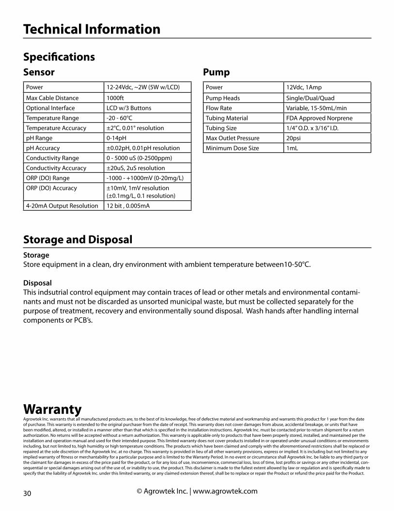
PumpPower 12Vdc, 1Amp
Pump Heads Single/Dual/Quad
Flow Rate Variable, 15-50mL/min
Tubing Material FDA Approved Norprene
Tubing Size 1/4” O.D. x 3/16” I.D.
Max Outlet Pressure 20psi
Minimum Dose Size 1mL
Power 12-24Vdc, ~2W (5W w/LCD)
Max Cable Distance 1000ft
Optional Interface LCD w/3 Buttons
Temperature Range -20 - 60°C
Temperature Accuracy ±2°C, 0.01° resolution
pH Range 0-14pH
pH Accuracy ±0.02pH, 0.01pH resolution
Conductivity Range 0 - 5000 uS (0-2500ppm)
Conductivity Accuracy ±20uS, 2uS resolution
ORP (DO) Range -1000 - +1000mV (0-20mg/L)
ORP (DO) Accuracy ±10mV, 1mV resolution(±0.1mg/L, 0.1 resolution)
4-20mA Output Resolution 12 bit , 0.005mA
SensorSpecifications
Technical Information
StorageStore equipment in a clean, dry environment with ambient temperature between10-50°C.
DisposalThis indsutrial control equipment may contain traces of lead or other metals and environmental contami-nants and must not be discarded as unsorted municipal waste, but must be collected separately for the purpose of treatment, recovery and environmentally sound disposal. Wash hands after handling internal components or PCB’s.
Storage and Disposal