nuttlar viaduct unites regions at a height of … · nuttlar viaduct unites regions at a height of...
TRANSCRIPT

Sborník 21. Betonářské dny (2014)
Sekce ST2A: Vyzvané přednášky
1
NUTTLAR VIADUCT UNITES REGIONS AT A HEIGHT OF 115
METRES
Gero Marzahn
Hans Grassl
Gerhard
Buddenkotte
Dieter
Schummer
Guido Bogdan
Abstract
The Nuttlar motorway viaduct is currently under construction in North Rhine Westphalia,
the most populated area in Germany with 18 million inhabitants. Because of its exposed
position, it sets extreme technical demands on the engineers in terms of the design and
implementation of the construction work. With a total length of 660 metres, it spans the
deep valley of the Schlebornbach at a height of 115 metres (pier height 110 metres). It is
part of the new 5.6 km section of the A46 between Bestwig/Velmede and Nuttlar.
Supported on six piers, the structure creates a well-proportioned geometry with seven
spans and ensures that impact on the landscape is minimised. Designed as a composite-
steel bridge, the steel superstructure was inserted over a maximum single span of
115 metres without the aid of auxiliary supports or pylons using an incremental launching
method, something completely new for Germany. The slab for the bridge deck has been
poured section-by-section since April. The viaduct is designed for a cross-section of RQ 26
with a usable width of 28.60 metres between the rails.
Klíčová slova: motorway viaduct, incremental launching method, composite-steel bridge
1 Introduction/basic parameters of the project
The Ruhr region is one of the largest urban centres in Europe, so that infrastructural
measures such as the expansion of traffic connections play a vital role here. One example
of such a measure is the new section of the A46 motorway between the Bestwig/Velmede
and Nuttlar intersections. The new Nuttlar viaduct is being built at the eastern end of the
existing motorway, closing a gap in the motorway network to the east. This creates a
continuous link between the economic areas of the eastern Ruhr and the upper part of the
Ruhr valley. At the same time, this new section of the motorway also establishes a better
connection between the recreation areas in the Sauerland and the urban areas of the Ruhr.

21. Betonářské dny (2014) Sborník
Sekce ST2A: Vyzvané přednášky
2
For the people of the region, the building project most importantly promises to
relieve the local traffic situation in the villages of the Sauerland along national road B 7.
Noise and exhaust emissions will tangibly decline and the attractiveness of the shopping
and business areas along the national route will rise, along with the corresponding
improvement in the quality of life for local residents.
The basis for the design manual and the associated project design was a precise
analysis of the area as well as the local geographical and socio-cultural conditions.
2 Project scope and special features
A total of 13 bridges and viaducts need to be built for the new 5.6 kilometre motorway
section. The Nuttlar viaduct will not only have the longest maximum span (115 metres),
but in future will also be the highest viaduct in the populous German state of North Rhine
Westphalia at 115 metres. It will cross the Schlebornbach valley and traverse several
forestry roads and service roads, as well as a secondary road L 776 (see Fig. 1).
Fig. 1 Future prospect: Rendering of the completed bridge © Ingenieurbüro Grassl GmbH
The structure is built on A-form converging piers of up to 110 metres height and
demands the extremely precise design and implementation. This is due to a number of
special features that had a major influence on the form and planning of the viaduct,
alongside the usual criteria.
the topology and geology of the narrow and steeply sloped valley,
problematic access to the hillside,
the need to protect adjoining developments from pollution,
the planned routing of the remainder of the motorway as a suspended viaduct,
the integration of the structure as part of the landscape,
the balance of the proportions of the structural design,

Sborník 21. Betonářské dny (2014)
Sekce ST2A: Vyzvané přednášky
3
cost-efficiency.
The line of the new motorway section in the area of the Nuttlar viaduct basically
represents a constant bend with a radius of 1,000 metres. The structure features a constant
longitudinal slope of 0.7%, while the camber is a constant 4.0%.
3 Designing principles and design concept
Because of their exposed position, large bridges like the Nuttlar viaduct are highly visible
from a variety of vantage points - the entire length of the viaduct can be seen from opposite
slopes. In order to guarantee a uniform group of bridges/viaducts along the new section of
motorway, certain design elements, such as cladding, pier and abutment pier shapes,
parapets and colouring have been standardised. This both ensures the desired
recognisability factor and underlines the way in which the individual structures belong to
the overall project.
When it comes to the placement of the piers, particular attention should be paid to
balanced proportions between the support width, structural height, topography and existing
constraint points. The chosen design on six piers, yielding a well-proportioned geometry of
the seven bridge spans, means that the impact on the landscape can be minimised, access to
the steep slopes can be assured via service roads and an attractive visual amenity can be
achieved. The distances between the support piers of up to 115 metres also makes the
support structure appear highly transparent (see Fig. 2).
Fig. 2 Building progress to end of August 2014 - pouring the bridge deck slab with underlying
formwork using the pilgering process. © Ingenieurbüro Grassl GmbH
The general topographical conditions of the deeply sloped valley with the necessary
pier heights of up to 110 metres favoured the choice of a single cross-section and thus the
decision to dispense with a second row of piers in order to minimise the impact on the
slope in the interests of easier access to the pier construction sites.

21. Betonářské dny (2014) Sborník
Sekce ST2A: Vyzvané přednášky
4
Because of the large intervals between the piers, it was only possible to use a
composite steel girder as the superstructure, enabling cost-efficient building in this interval
range. The steep sides of the valley and the consequent limited access to the pier locations
led to the decision to build the superstructure using the launching method. Achieving a
span of 115 metres using the launching method was first in Germany.
4 Planning and design of foundation, abutment, pier and
superstructure
With one exception, flat foundations on the non-weathered rock were chosen for the
foundations of the viaduct's abutments and piers. The developed area belongs to the north-
eastern part of the Rhineland Schiefer mountain range. The box-shaped abutments were
built in class C 30/37 reinforced concrete and S 500 reinforcing steel. The internal space of
the abutment has two accessible levels for the inspection of the reinforced concrete
construction, the bearing and the bridge deck expansion joints.
The piers have solid reinforced concrete circular cross-sections with constant
diameters of 3.0, 4.0 and 5.0 metres in order to achieve the architectural design
requirements (see Fig. 3). Due to the great height of the piers, horizontal bars made of
concrete-filled steel profiles with diameters of 2.0 and 3.0 metres link the round supports.
The pier heads and support plinths are made from strength class C 40/50 concrete;
the piers, foundations and piles are made from class C 30/37 concrete, with S 500
reinforcing steel.
Fig. 3 Piers made from reinforced concrete cross-sections as double round piers in A form.
© Ingenieurbüro Grassl GmbH
Sborník 21. Betonářské dny (2014)
Sekce ST2A: Vyzvané přednášky
5
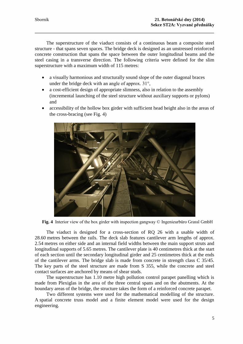
The superstructure of the viaduct consists of a continuous beam a composite steel
structure - that spans seven spaces. The bridge deck is designed as an unstressed reinforced
concrete construction that spans the space between the outer longitudinal beams and the
steel casing in a transverse direction. The following criteria were defined for the slim
superstructure with a maximum width of 115 metres:
a visually harmonious and structurally sound slope of the outer diagonal braces
under the bridge deck with an angle of approx. 31°,
a cost-efficient design of appropriate slimness, also in relation to the assembly
(incremental launching of the steel structure without auxiliary supports or pylons)
and
accessibility of the hollow box girder with sufficient head height also in the areas of
the cross-bracing (see Fig. 4)
Fig. 4 Interior view of the box girder with inspection gangway © Ingenieurbüro Grassl GmbH
The viaduct is designed for a cross-section of RQ 26 with a usable width of
28.60 metres between the rails. The deck slab features cantilever arm lengths of approx.
2.54 metres on either side and an internal field widths between the main support struts and
longitudinal supports of 5.65 metres. The cantilever plate is 40 centimetres thick at the start
of each section until the secondary longitudinal girder and 25 centimetres thick at the ends
of the cantilever arms. The bridge slab is made from concrete in strength class C 35/45.
The key parts of the steel structure are made from S 355, while the concrete and steel
contact surfaces are anchored by means of shear studs.
The superstructure has 1.10 metre high pollution control parapet panelling which is
made from Plexiglas in the area of the three central spans and on the abutments. At the
boundary areas of the bridge, the structure takes the form of a reinforced concrete parapet.
Two different systems were used for the mathematical modelling of the structure.
A spatial concrete truss model and a finite element model were used for the design
engineering.

21. Betonářské dny (2014) Sborník
Sekce ST2A: Vyzvané přednášky
6
5 Construction using the incremental launching method
The superstructure was launched over the valley in eight sections. For this launching
bearings were installed on the piers and abutments of axes 20 to 80 and in axes V1 to V3
under the web plate of the box girder, which were hydraulically linked at each bearing
point of the bearing axis. The top of the displacement bearing corresponded to the gradient
level in the bottom line of the bridge. The guidance was achieved by Teflon/Steel pairing.
The concreting of the deck slab is done with formwork carriages (see Fig. 5). The
length of the concreting section is approx. 24 metres, so that six pivoting formwork
carriage elements are linked together. By using a formwork carriage placed below the
deck, penetrations of the deck slab with tension rods are not needed.
Fig. 5 Pouring the bridge deck slab with underlying formwork © Ingenieurbüro Grassl GmbH
6 Outlook
After final completion, the new 5.6 km section will not only facilitate a high-performance
traffic connection in one of the busiest urban centres in Europe, but will also underline the
expertise of Germany's bridge builders (see Fig. 6).

Sborník 21. Betonářské dny (2014)
Sekce ST2A: Vyzvané přednášky
7
Fig. 6 Rendering of the completed bridge © Ingenieurbüro Grassl GmbH
7 Project participants
Client:
The Federal Republic of Germany, represented by Landesbetrieb Straßenbau NRW,
Regionalniederlassung Sauerland-Hochstift
Architectural concept:
Ruhrberg Ingenieurgemeinschaft, Hagen, Dipl.-Ing. arch. I. Neumann and W. Neumann
Preliminary design:
Landesbetrieb Straßenbau NRW, Regionalniederlassung Sauerland-Hochstift, Meschede
Basic design:
Ingenieurbüro Grassl GmbH, Düsseldorf
Geotechnical engineers:
Prof. Dr.-Ing. W. Wittke Beratende Ingenieure für Grundbau und Felsbau GmbH, Aachen
Structural design check:
W. Neumann, Hagen
Building contractor:
Max Bögl Bauunternehmung GmbH & Co.KG, Neumarkt
Onsite construction management:
Landesbetrieb Straßenbau NRW, Regionalniederlassung Sauerland-Hochstift
Production supervision of steel construction and anti-corrosion treatment:
Lavis Engineering GmbH, Halle

21. Betonářské dny (2014) Sborník
Sekce ST2A: Vyzvané přednášky
8
Literatura
[1] Marzahn, G.; Grassl, H.; Schummer, D.; Buddenkotte, G.; Bogdan, G. Neubau der
Talbrücke Nuttlar bei Bestwig – höchste Talbrücke in Nordrhein-Westfalen.
Tagungsband 24. Dresdner Brückenbausymposium 03 2014, S. 107 - 126.
[2] Grassl, H.; Schummer, D.; Bogdan, G.; Buddenkotte, G. Entwurf, Planung und
Ausführung – Bau der Talbrücke Nuttlar. Wiederspahn, M. (Hrsg.): Brückenbau –
Construction & Engineering, 13. Symposium Brückenbau in Leipzig . Ausgabe 1/2
2013. Wiesbaden: Verlagsgruppe Wiederspahn, 2013, S. 71 - 79.
Dr.-Ing. Gero Marzahn, Abt.-ltr. Landesbetrieb Straßenbau NRW
Hauptabteilung 3 (Bau)
Abteilung Konstruktiver Ingenieurbau
Wildenbruchplatz 1
45888 Gelsenkirchen
Germany
+49-(0)209-3808-494
+49-(0)209-3808-380
URL www.straßen.nrw.de
Dr. Hans Grassl Ingenieurbüro Grassl GmbH
Adlerstraße 34-40
40211 Düsseldorf
Germany
+49 211 17597-20
+49 211 17597-90
URL www.grassl-ing.de
Dipl.-Ing. Gerhard Buddenkotte Landesbetrieb Straßenbau NRW
Regionalniederlassung Sauerland-
Hochstift
Lanfertsweg 2, 59872 Meschede
Germany
+49 291 298-561
+49 291 298-590
URL www.strassen.nrw.de
Dipl.-Ing. Dieter Schummer Max Bögl Bauu. GmbH & Co. KG
Postfach 11 20
92301 Neumarkt
Germany
+49 (9181) 909-10549
+49 (9181) 909-87 10549
URL www.may-boegl.de
Dipl.-Ing. Guido Bogdan Ingenieurbüro Grassl GmbH
Adlerstraße 34-40
40211 Düsseldorf
Germany
+49 211 17597-86
+49 211 17597-90
URL www.grassl-ing.de