nva design guide - netapp: data services for hybrid … components are connected and configured...
TRANSCRIPT
NetApp Verified Architecture
FlexPod Datacenter with NetApp MetroCluster NVA Design Guide
Aaron Kirk, David Klem, Arvind Ramakrishnan, NetApp
September 2016 | NVA-0030-DESIGN | Version 1.0
Reviewed by
2 FlexPod Datacenter with NetApp MetroCluster Design Guide © 2016 NetApp, Inc. All Rights Reserved.
TABLE OF CONTENTS
1 Executive Summary.............................................................................................................................. 4
2 Program Summary................................................................................................................................ 4
3 FlexPod Design Principles .................................................................................................................. 4
4 Solution Overview ................................................................................................................................ 5
4.1 Solution Technology ....................................................................................................................................... 6
4.2 Target Audience .............................................................................................................................................. 7
4.3 Use Case Summary ........................................................................................................................................ 8
5 Technology Requirements .................................................................................................................. 8
5.1 Hardware Requirements ................................................................................................................................. 8
5.2 Software Requirements .................................................................................................................................. 9
6 Design Decisions .................................................................................................................................. 9
6.1 NetApp MetroCluster ...................................................................................................................................... 9
6.2 Cisco Nexus .................................................................................................................................................. 15
6.3 Site-to-Site Connectivity (OTV) ..................................................................................................................... 17
6.4 Cisco UCS (Server Types / UCS Central) ..................................................................................................... 19
6.5 NetApp FAS and ONTAP .............................................................................................................................. 22
6.6 VMware vSphere .......................................................................................................................................... 24
7 Solution Verification ........................................................................................................................... 25
8 Conclusion .......................................................................................................................................... 26
References ................................................................................................................................................. 26
Version History ......................................................................................................................................... 27
LIST OF TABLES
Table 1) Hardware requirements. ................................................................................................................................... 8
Table 2) Software requirements. .................................................................................................................................... 9
Table 3) Maximum supported distance with Cisco MDS switches. ............................................................................... 13
Table 4) Cisco UCS FEX ports. .................................................................................................................................... 20
LIST OF FIGURES
Figure 1) Single-site solution topology. .......................................................................................................................... 5
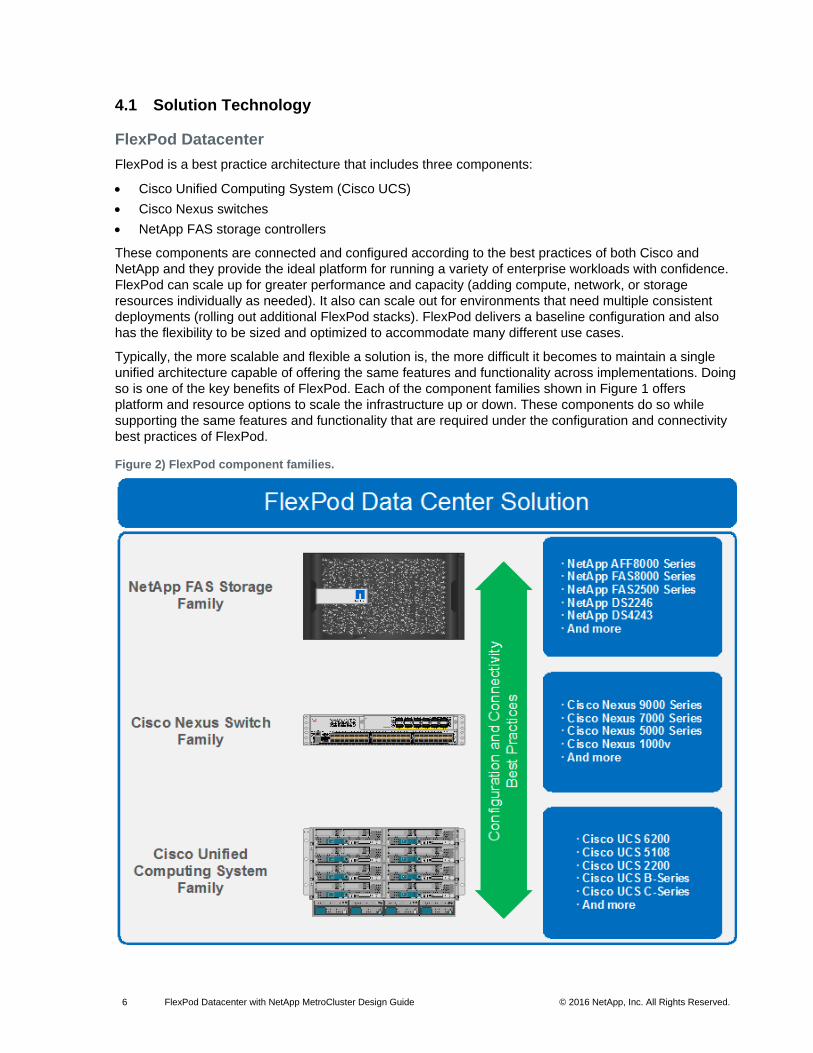
Figure 2) FlexPod component families. .......................................................................................................................... 6
Figure 3) Cisco OTV. ...................................................................................................................................................... 7
Figure 4) Two-node MetroCluster in optical SAS configuration. ................................................................................... 10

3 FlexPod Datacenter with NetApp MetroCluster Design Guide © 2016 NetApp, Inc. All Rights Reserved.
Figure 5) Two-node MetroCluster in bridge-attached configuration. ............................................................................. 11
Figure 6) Two-node MetroCluster in fabric configuration. ............................................................................................. 11
Figure 7) Four-node MetroCluster configuration. .......................................................................................................... 12
Figure 8) Cross-site connectivity. ................................................................................................................................. 12
Figure 9) Cross-site connectivity loss. .......................................................................................................................... 14
Figure 10) Cisco Nexus 9000 connections. .................................................................................................................. 16
Figure 11) Stretch cluster without OTV......................................................................................................................... 18
Figure 12) Stretched cluster with OTV.......................................................................................................................... 18
Figure 13) Discrete mode versus PortChannel mode. .................................................................................................. 20
Figure 14) Cisco UCS Central. ..................................................................................................................................... 22
Figure 15) NetApp disk options. ................................................................................................................................... 23
4 FlexPod Datacenter with NetApp MetroCluster Design Guide © 2016 NetApp, Inc. All Rights Reserved.
1 Executive Summary
Industry trends indicate a shift in the data center. Business pressures and operational limitations are
pushing organizations to rethink how they build and manage their data center environments. Enterprise
customers increasingly reduce cost and increase their business agility by moving toward cost-effective
virtualized infrastructures.
As businesses consolidate their enterprise applications on shared virtual infrastructure, the availability of
this business-critical data becomes an important factor. The loss of availability from unplanned downtime
of these applications can cause customers up to $7,800 a minute. Because of this significant cost to the
business, customers might want to consider a converged infrastructure solution that provides zero data
loss and recovery of applications within minutes instead of hours.
NetApp, Cisco, and VMware provide a solution that takes the risk out of deploying a large converged
infrastructure solution focused on flexibility, risk reduction, and performance in addition to business-
continuity needs. FlexPod® Datacenter with NetApp® MetroCluster™ was developed to meet the needs of
customers who want to deploy this kind of solution.
FlexPod already has built-in features to help improve availability:
Active-active high availability (HA) across the entire stack of compute, network, and storage
Network and storage quality of service (QoS)
Multiple redundant connections from the servers through the network to the back-end connectivity between the storage controllers and disks
Nondisruptive operations to seamlessly move virtual machines (VMs) between hosts in the compute cluster or to move either VM or user data within the storage cluster without affecting the user
MetroCluster adds to the high availability of the FlexPod platform by separating two clusters of storage by
up to 300km. Doing so gives customers the ability to switch control over to a surviving site in the event of
an outage at one site.
2 Program Summary
The NetApp Verified Architecture (NVA) program offers customers a verified architecture for NetApp
solutions. An NVA provides you with a NetApp solution architecture that:
Is thoroughly tested
Is prescriptive in native
Minimizes deployment risks
Accelerates time to market
This guide details the design of the FlexPod Datacenter with NetApp MetroCluster solution. NetApp
MetroCluster provides continuous availability for business-critical applications at lower cost and
complexity.
3 FlexPod Design Principles
FlexPod addresses four primary design principles: availability, scalability, flexibility, and manageability.
The architecture goals are as follows:
Availability. Makes sure that services are accessible and ready for use by the applications.
Scalability. Addresses increasing demands with appropriate resources.
Flexibility. Provides new services or recovers resources without requiring infrastructure modification.
Manageability. Facilitates efficient infrastructure operations through open standards and APIs.

5 FlexPod Datacenter with NetApp MetroCluster Design Guide © 2016 NetApp, Inc. All Rights Reserved.
4 Solution Overview
In today’s data center, unplanned downtime of business-critical infrastructure causes lost revenue and
user productivity loss. NetApp MetroCluster provides a zero recovery point objective (RPO) along with a
near-zero recovery time objective (RTO) to provide continuous data availability for mission-critical
applications. FlexPod Datacenter with NetApp MetroCluster combines the continuous availability of
MetroCluster with FlexPod Datacenter, which contains Cisco Unified Computing System (Cisco UCS),
Cisco Nexus networking, and VMware vSphere in a validated design. This design reduces the risk and
complexity of deploying business-critical infrastructure. Figure 1 displays the connectivity of one site of
the solution. Connectivity is identical in both solution sites.
Figure 1) Single-site solution topology.
6 FlexPod Datacenter with NetApp MetroCluster Design Guide © 2016 NetApp, Inc. All Rights Reserved.
4.1 Solution Technology
FlexPod Datacenter
FlexPod is a best practice architecture that includes three components:
Cisco Unified Computing System (Cisco UCS)
Cisco Nexus switches
NetApp FAS storage controllers
These components are connected and configured according to the best practices of both Cisco and
NetApp and they provide the ideal platform for running a variety of enterprise workloads with confidence.
FlexPod can scale up for greater performance and capacity (adding compute, network, or storage
resources individually as needed). It also can scale out for environments that need multiple consistent
deployments (rolling out additional FlexPod stacks). FlexPod delivers a baseline configuration and also
has the flexibility to be sized and optimized to accommodate many different use cases.
Typically, the more scalable and flexible a solution is, the more difficult it becomes to maintain a single
unified architecture capable of offering the same features and functionality across implementations. Doing
so is one of the key benefits of FlexPod. Each of the component families shown in Figure 1 offers
platform and resource options to scale the infrastructure up or down. These components do so while
supporting the same features and functionality that are required under the configuration and connectivity
best practices of FlexPod.
Figure 2) FlexPod component families.
7 FlexPod Datacenter with NetApp MetroCluster Design Guide © 2016 NetApp, Inc. All Rights Reserved.
NetApp MetroCluster
NetApp MetroCluster is a solution that combines array-based clustering with synchronous replication to
deliver continuous availability and zero data loss at the lowest cost. Administration of the array-based
cluster is simpler because the dependencies and complexity normally associated with host-based
clustering are eliminated. MetroCluster immediately duplicates all your mission-critical data on a
transaction-by-transaction basis, providing uninterrupted access to your applications and data. Unlike
standard data-replication solutions, MetroCluster works seamlessly with your host environment to provide
continuous data availability while eliminating the need to create and maintain failover scripts.
For more information on MetroCluster, see the MetroCluster page on netapp.com.
VMware vSphere Metro Storage Cluster (vMSC)
VMware vMSC is a specific type of configuration for a VMware vSphere cluster in a stretched cluster
environment. NetApp MetroCluster is a certified vMSC configuration designed to maintain data availability
beyond a single location in many different failure scenarios. This deployment guide describes the best
practices to follow when configuring a vSphere cluster on FlexPod Datacenter with NetApp MetroCluster.
The primary advantage of the vMSC best practices FlexPod Datacenter with NetApp MetroCluster is that
they take advantage of the active-active data availability of NetApp MetroCluster. They do so while
maintaining the capability to use vMotion with VMs between the two sites to prevent application
downtime.
The best practices to follow include using these VMware technologies:
VMware vSphere HA
VMware vSphere DRS
VMware VM-to-host affinity rules
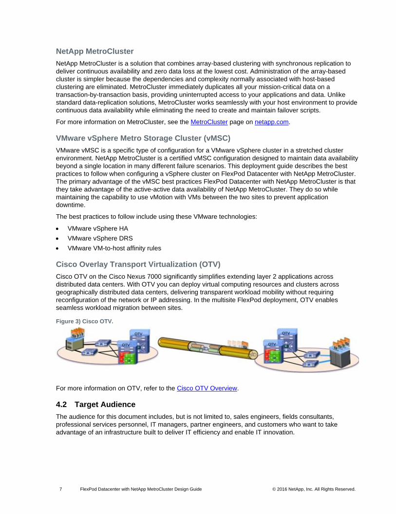
Cisco Overlay Transport Virtualization (OTV)
Cisco OTV on the Cisco Nexus 7000 significantly simplifies extending layer 2 applications across
distributed data centers. With OTV you can deploy virtual computing resources and clusters across
geographically distributed data centers, delivering transparent workload mobility without requiring
reconfiguration of the network or IP addressing. In the multisite FlexPod deployment, OTV enables
seamless workload migration between sites.
Figure 3) Cisco OTV.
For more information on OTV, refer to the Cisco OTV Overview.
4.2 Target Audience
The audience for this document includes, but is not limited to, sales engineers, fields consultants,
professional services personnel, IT managers, partner engineers, and customers who want to take
advantage of an infrastructure built to deliver IT efficiency and enable IT innovation.
8 FlexPod Datacenter with NetApp MetroCluster Design Guide © 2016 NetApp, Inc. All Rights Reserved.
4.3 Use Case Summary
FlexPod Datacenter with NetApp MetroCluster is a flexible architecture that can be sized and optimized to
accommodate a wide variety of use cases. This deployment focuses on a fabric MetroCluster
environment stretched to 300km to show the solution’s capabilities to effectively span distances. This
solution can be scaled down for a single campus or a single data center.
This solution applies to the following use cases:
Maintaining data access during outages and disasters
Simplifying disaster recovery management
Simplifying management of infrastructure located in multiple sites
5 Technology Requirements
This section covers the technology requirements for the FlexPod Datacenter with NetApp MetroCluster
solution.
5.1 Hardware Requirements
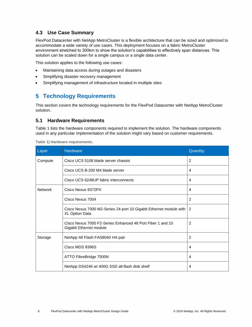
Table 1 lists the hardware components required to implement the solution. The hardware components
used in any particular implementation of the solution might vary based on customer requirements.
Table 1) Hardware requirements.
Layer Hardware Quantity
Compute Cisco UCS 5108 blade server chassis 2
Cisco UCS B-200 M4 blade server 4
Cisco UCS 6248UP fabric interconnects 4
Network Cisco Nexus 9372PX 4
Cisco Nexus 7004 2
Cisco Nexus 7000 M2-Series 24-port 10 Gigabit Ethernet module with XL Option Data
2
Cisco Nexus 7000 F2-Series Enhanced 48 Port Fiber 1 and 10 Gigabit Ethernet module
2
Storage NetApp All Flash FAS8040 HA pair 2
Cisco MDS 9396S 4
ATTO FibreBridge 7500N 4
NetApp DS4246 w/ 400G SSD all-flash disk shelf 4

9 FlexPod Datacenter with NetApp MetroCluster Design Guide © 2016 NetApp, Inc. All Rights Reserved.
5.2 Software Requirements
Table 2 lists the software components required to implement the solution. The software components used
in any particular implementation of the solution might vary based on customer requirements.
Table 2) Software requirements.
Layer Software Version or Release
Compute Cisco UCS fabric interconnects 6200 Series, UCS B-200 M4, UCS C-220 M4
2.2(5d)
Cisco eNIC 2.1.2.71
Cisco fNIC 1.6.0.17a
Cisco UCS Central 1.4(1b)
Network Cisco Nexus 9372PX 7.0(3)I2(1)
Cisco Nexus 7004 7.3(0)D1(1)
Storage NetApp All Flash FAS8040 HA pair Data ONTAP® 8.3.2
Cisco MDS 9396S 6.2(15)
ATTO FibreBridge 7500N 2.41
Software VMware vSphere ESXi 6.0
VMware vCenter 6.0
NetApp Virtual Storage Console 6.2
NetApp OnCommand® Unified Manager 6.4
NetApp OnCommand Performance Manager 2.1
6 Design Decisions
6.1 NetApp MetroCluster
Thousands of enterprises worldwide have implemented NetApp MetroCluster to protect their mission-
critical applications. MetroCluster provides high availability, zero data loss, and nondisruptive operations
beyond the data center. In today’s world of infrastructure consolidation in the data center, it is critical that
the infrastructure for key applications maintains availability of data and services throughout a wide range
of outages. It is for this reason that this solution is built on storage protected by MetroCluster.
MetroCluster can be implemented in various sizes for different customer needs. Various configurations,
from configurations that consist of two NetApp controllers to configurations that include eight NetApp
controllers, are available.
Configurations with two controllers use the remote site for high availability (HA) functionality as well as for
disaster recovery (DR) functionality. These configurations use less hardware and are more suited for
smaller workloads or shorter campus distances. Configurations with four or more controllers are better

10 FlexPod Datacenter with NetApp MetroCluster Design Guide © 2016 NetApp, Inc. All Rights Reserved.
suited to large enterprises because of the wide range of distances supported and the ability to execute
HA operations locally instead of being required to fail over to the other site.
Recovery Point Objective and Recovery Time Objective Requirements
Businesses have a wide variety of backup options available to them. Before choosing a solution’s
components, they should fully understand the needs of their infrastructure and applications in terms of
recovery point objective and recovery time objective.
The recovery point objective (RPO) is the amount of time that passed since the last time a backup was
taken. If an occurrence caused a loss of the infrastructure, all data written since the last backup is lost.
Although some use cases can withstand the loss of data, many shared infrastructures and virtualized
environments need backups to be taken in minutes instead of hours. NetApp SnapMirror® and NetApp
MetroCluster are two solutions for these shared infrastructure environments that need to keep data loss
to a minimum.
The recovery time objective (RTO) is the amount of time a business is willing to wait until applications are
back up and running. Many infrastructures need to be able to withstand outages with minimal downtime to
enable business continuity.
FlexPod Datacenter with MetroCluster contains redundancy at every layer in the infrastructure stack so
that data continues to be served in the event any component fails. Additionally, the solution features a
stretched cluster environment. The clusters can be separated by a distance of up to 300km. Even in the
event of a regional power outage or a natural disaster, control can be switched to the surviving site and
applications can continue to run with minimal downtime.
FlexPod solutions are available for a wide variety of RPO and RTO needs. For businesses that require
continuous availability with zero data loss, FlexPod Datacenter with NetApp MetroCluster can be
leveraged to create a reliable, virtualized shared infrastructure.
MetroCluster Configurations
Two-Node MetroCluster with Optical SAS
In the two-node MetroCluster configuration with optical SAS, there is a single node cluster at each site.
Each node is directly connected to local and remote disks using optical SAS cables. The maximum
distance available in this configuration is 500m. Failover to the other cluster is required for both HA and
DR operations. The switchover automatically occurs in this configuration if the other node in the
MetroCluster system goes down for any reason. This configuration is good for synchronous replication
over a shorter distance, such as between two buildings on a campus.
Figure 4) Two-node MetroCluster in optical SAS configuration.

11 FlexPod Datacenter with NetApp MetroCluster Design Guide © 2016 NetApp, Inc. All Rights Reserved.
Two-Node MetroCluster with ATTO FibreBridge
The two-node MetroCluster configuration with ATTO FibreBridge is similar to the two-node configuration
with optical SAS. The two nodes in this configuration are each single clusters peered together. The
maximum distance between them is 500m. The difference is that in this configuration, the controllers are
connected directly to the FibreBridge instead of being connected directly to shelves or to switches. The
two-node MetroCluster with ATTO FibreBridge might be preferable to customers who prefer multimode
fiber connections between sites.
Figure 5) Two-node MetroCluster in bridge-attached configuration.
Two-Node Fabric MetroCluster
In this configuration, the two nodes are connected to the disks through switches and FibreBridge
controllers. The use of FC switches in this configuration enables you to leverage the maximum distance
of the switch. See Table 3 for the maximum distance supported by each Cisco MDS switch.
Figure 6) Two-node MetroCluster in fabric configuration.
Four-Node Fabric MetroCluster
The four-node MetroCluster system, as depicted in Figure 7, is the primary configuration for NetApp
MetroCluster today and the configuration utilized in the FlexPod Datacenter with NetApp MetroCluster
Deployment Guide. In this configuration, four nodes are connected to the local and remote disks by Fibre
Channel (FC) or Fibre Channel over IP (FCIP) switches. A number of Cisco MDS switches are supported
in this configuration, each with different specifications and supported for a different maximum distance
between sites.
12 FlexPod Datacenter with NetApp MetroCluster Design Guide © 2016 NetApp, Inc. All Rights Reserved.
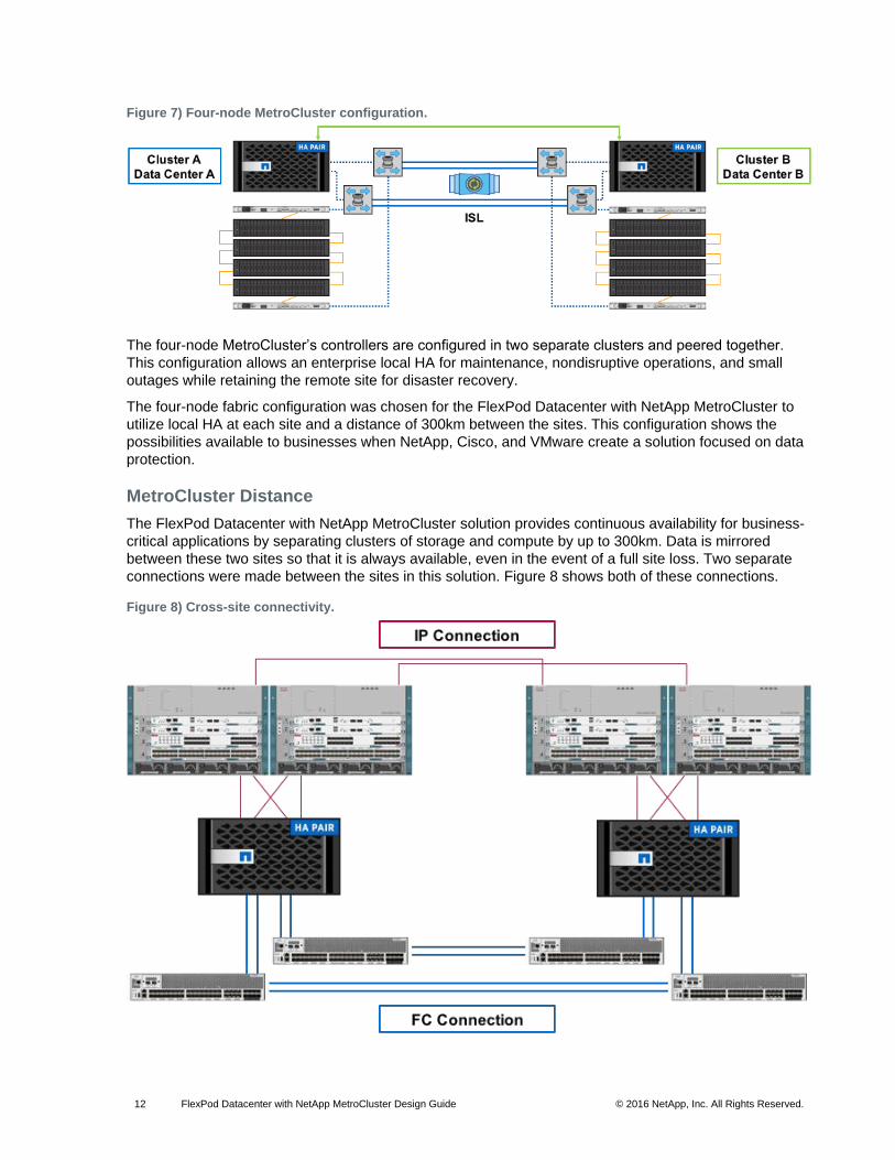
Figure 7) Four-node MetroCluster configuration.
The four-node MetroCluster’s controllers are configured in two separate clusters and peered together.
This configuration allows an enterprise local HA for maintenance, nondisruptive operations, and small
outages while retaining the remote site for disaster recovery.
The four-node fabric configuration was chosen for the FlexPod Datacenter with NetApp MetroCluster to
utilize local HA at each site and a distance of 300km between the sites. This configuration shows the
possibilities available to businesses when NetApp, Cisco, and VMware create a solution focused on data
protection.
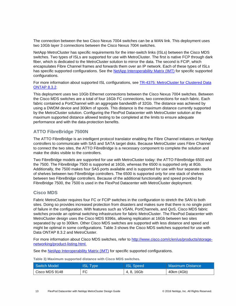
MetroCluster Distance
The FlexPod Datacenter with NetApp MetroCluster solution provides continuous availability for business-
critical applications by separating clusters of storage and compute by up to 300km. Data is mirrored
between these two sites so that it is always available, even in the event of a full site loss. Two separate
connections were made between the sites in this solution. Figure 8 shows both of these connections.
Figure 8) Cross-site connectivity.
13 FlexPod Datacenter with NetApp MetroCluster Design Guide © 2016 NetApp, Inc. All Rights Reserved.
The connection between the two Cisco Nexus 7004 switches can be a WAN link. This deployment uses
two 10Gb layer 3 connections between the Cisco Nexus 7004 switches.
NetApp MetroCluster has specific requirements for the inter-switch links (ISLs) between the Cisco MDS
switches. Two types of ISLs are supported for use with MetroCluster. The first is native FCP through dark
fiber, which is dedicated to the MetroCluster solution to mirror the data. The second is FCIP, which
encapsulates Fibre Channel frames and forwards them over an IP network. Each of these types of ISLs
has specific supported configurations. See the NetApp Interoperability Matrix (IMT) for specific supported
configurations.
For more information about supported ISL configurations, see TR-4375: MetroCluster for Clustered Data
ONTAP 8.3.2.
This deployment uses two 10Gb Ethernet connections between the Cisco Nexus 7004 switches. Between
the Cisco MDS switches are a total of four 16Gb FC connections, two connections for each fabric. Each
fabric contained a PortChannel with an aggregate bandwidth of 32Gb. The distance was achieved by
using a DWDM device and 300km of spools. This distance is the maximum distance currently supported
by the MetroCluster solution. Configuring the FlexPod Datacenter with MetroCluster solution at the
maximum supported distance allowed testing to be completed at the limits to ensure adequate
performance and with the data-protection benefits.
ATTO FibreBridge 7500N
The ATTO FibreBridge is an intelligent protocol translator enabling the Fibre Channel initiators on NetApp
controllers to communicate with SAS and SATA target disks. Because MetroCluster uses Fibre Channel
to connect the two sites, the ATTO FibreBridge is a necessary component to complete the solution and
make the disks visible to the controllers.
Two FibreBridge models are supported for use with MetroCluster today: the ATTO FibreBridge 6500 and
the 7500. The FibreBridge 7500 is supported at 16Gb, whereas the 6500 is supported only at 8Gb.
Additionally, the 7500 makes four SAS ports available and is supported for use with four separate stacks
of shelves between two FibreBridge controllers. The 6500 is supported only for one stack of shelves
between two FibreBridge controllers. Because of the additional functionality and speed provided by
FibreBridge 7500, the 7500 is used in the FlexPod Datacenter with MetroCluster deployment.
Cisco MDS
Fabric MetroCluster requires four FC or FCIP switches in the configuration to stretch the SAN to both
sites. Doing so provides increased protection from disasters and makes sure that there is no single point
of failure in the configuration. With features such as VSAN, PortChannels, and QoS, Cisco MDS fabric
switches provide an optimal switching infrastructure for fabric MetroCluster. The FlexPod Datacenter with
MetroCluster design uses the Cisco MDS 9396s, allowing replication at 16Gb between two sites
separated by up to 300km. Other Cisco MDS switches are supported with less distance and speed and
might be optimal in some configurations. Table 3 shows the Cisco MDS switches supported for use with
Data ONTAP 8.3.2 and MetroCluster.
For more information about Cisco MDS switches, refer to http://www.cisco.com/c/en/us/products/storage-
networking/product-listing.html.
See the NetApp Interoperability Matrix (IMT) for specific supported configurations.
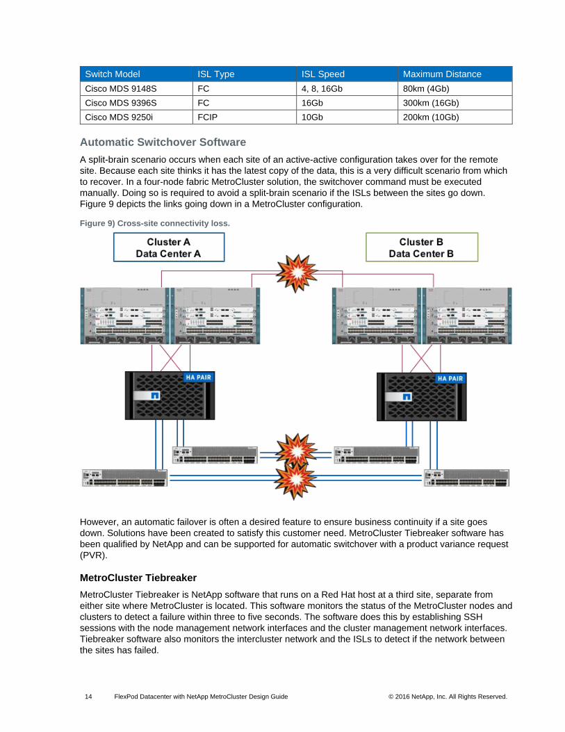
Table 3) Maximum supported distance with Cisco MDS switches.
Switch Model ISL Type ISL Speed Maximum Distance
Cisco MDS 9148 FC 4, 8, 16Gb 40km (4Gb)
14 FlexPod Datacenter with NetApp MetroCluster Design Guide © 2016 NetApp, Inc. All Rights Reserved.
Switch Model ISL Type ISL Speed Maximum Distance
Cisco MDS 9148S FC 4, 8, 16Gb 80km (4Gb)
Cisco MDS 9396S FC 16Gb 300km (16Gb)
Cisco MDS 9250i FCIP 10Gb 200km (10Gb)
Automatic Switchover Software
A split-brain scenario occurs when each site of an active-active configuration takes over for the remote
site. Because each site thinks it has the latest copy of the data, this is a very difficult scenario from which
to recover. In a four-node fabric MetroCluster solution, the switchover command must be executed
manually. Doing so is required to avoid a split-brain scenario if the ISLs between the sites go down.
Figure 9 depicts the links going down in a MetroCluster configuration.
Figure 9) Cross-site connectivity loss.
However, an automatic failover is often a desired feature to ensure business continuity if a site goes
down. Solutions have been created to satisfy this customer need. MetroCluster Tiebreaker software has
been qualified by NetApp and can be supported for automatic switchover with a product variance request
(PVR).
MetroCluster Tiebreaker
MetroCluster Tiebreaker is NetApp software that runs on a Red Hat host at a third site, separate from
either site where MetroCluster is located. This software monitors the status of the MetroCluster nodes and
clusters to detect a failure within three to five seconds. The software does this by establishing SSH
sessions with the node management network interfaces and the cluster management network interfaces.
Tiebreaker software also monitors the intercluster network and the ISLs to detect if the network between
the sites has failed.

15 FlexPod Datacenter with NetApp MetroCluster Design Guide © 2016 NetApp, Inc. All Rights Reserved.
By default, NetApp MetroCluster Tiebreaker software alerts an administrator to the failure of a site when it
occurs. A PVR is required to enable Tiebreaker software to automatically switch over the cluster in a
failure scenario.
For more information on MetroCluster Tiebreaker software, see the Tiebreaker Software 1.1 Installation
and Configuration Guide.
6.2 Cisco Nexus
The FlexPod Datacenter with MetroCluster design expands and extends the standard single-site FlexPod
architecture across multiple sites. Therefore, numerous factors must be taken into account when
choosing the main data switch in this type of architecture to support both the scale and the protocols
required for the resulting applications. All Cisco Nexus switch models including the Cisco Nexus 5000 and
7000 are supported in this design and might provide additional features such as FCoE or OTV. However,
be aware that there might be slight differences in setup and configuration based on the switch used. This
particular validation leverages Cisco 9000 series switches, which deliver proven high performance and
density, low latency, and exceptional power efficiency in a broad range of compact form factors.
Many of the most recent single-site FlexPod designs also use this switch because of the advanced
feature set and the ability to support Application Centric Infrastructure (ACI) mode. When leveraging ACI
fabric mode, the Cisco Nexus 9000 series switches are deployed in a spine-leaf architecture. Although
the reference architecture covered in this design does not leverage ACI, it lays the foundation for
customer migration to ACI in the future, and fully supports ACI today if required.
For more information, refer to http://www.cisco.com/c/en/us/products/switches/nexus-9000-series-
switches/index.html.
This FlexPod design deploys a single pair of Cisco Nexus 9000 top-of-rack switches at each site in
traditional deployment mode running Cisco NX-OS, essentially creating individual FlexPod units at both
locations.
The traditional deployment model delivers numerous benefits for this design:
High performance and scalability with L2 and L3 support per port (up to 60Tbps of nonblocking performance with less than 5-microsecond latency)
Layer 2 multipathing with all paths forwarding through the virtual PortChannel (vPC) technology
VXLAN support at line rate
Advanced reboot capabilities include hot and cold patching
Hot-swappable power-supply units and fans with N+1 redundancy
Cisco Nexus 9000 switches provide Ethernet switching fabric for communications between the Cisco UCS
domain, the NetApp storage system, and the enterprise network. In the FlexPod design, Cisco UCS fabric
interconnects and NetApp storage systems are connected to the Cisco Nexus 9000 switches using virtual
PortChannels.
Virtual PortChannel (vPC)
A virtual PortChannel (vPC) allows links that are physically connected to two different Cisco Nexus 9000
Series devices to appear as a single PortChannel. In a switching environment, vPC provides the following
benefits:
Allows a single device to use a PortChannel across two upstream devices
Eliminates Spanning Tree Protocol blocked ports and use all available uplink bandwidth
Provides a loop-free topology
Provides fast convergence if either one of the physical links or a device fails
Helps ensure high availability of the overall FlexPod system

16 FlexPod Datacenter with NetApp MetroCluster Design Guide © 2016 NetApp, Inc. All Rights Reserved.
Figure 10) Cisco Nexus 9000 connections.
Figure 10 shows the connections between Cisco Nexus 9000, UCS fabric interconnects, and NetApp
AFF8040. vPC requires a “peer link,” which is documented as PortChannel 10 in this diagram. In addition
to the vPC peer link, the vPC peer keepalive link is a required component of a vPC configuration. The
peer keepalive link allows each vPC-enabled switch to monitor the health of its peer. This link accelerates
convergence and reduces the occurrence of split-brain scenarios. In this validated solution, the vPC peer
keepalive link uses the out-of-band management network. This link is not shown in Figure 10.
Enabled Cisco Nexus 9000 Features
Link Aggregation Control Protocol (LACP, part of 802.3ad)
Cisco Virtual Port Channeling (vPC) for link and device resiliency
Enable Cisco Discovery Protocol (CDP) for infrastructure visibility and troubleshooting
Considerations for vPC
Define a unique domain ID.
Set the priority of the intended vPC primary switch lower than the secondary (default priority is 32768).
Establish peer keepalive connectivity. NetApp recommends using the out-of-band management network (mgmt0) or a dedicated switched virtual interface.
Enable vPC autorecovery feature.
Enable peer-gateway. Peer-gateway allows a vPC switch to act as the active gateway for packets that are addressed to the router MAC address of the vPC peer, allowing vPC peers to forward traffic.
Enable IP ARP synchronization to optimize convergence across the vPC peer link.
A minimum of two 10GbE connections are required for vPC.
All PortChannels should be configured in LACP active mode.
17 FlexPod Datacenter with NetApp MetroCluster Design Guide © 2016 NetApp, Inc. All Rights Reserved.
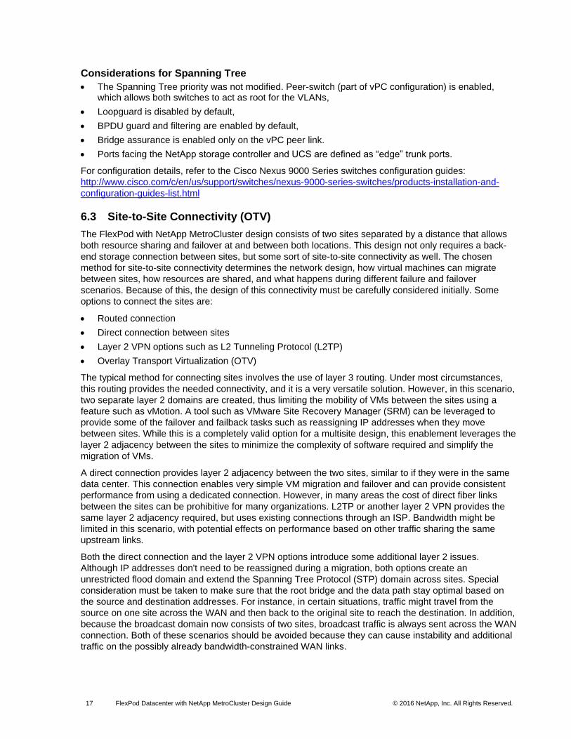
Considerations for Spanning Tree
The Spanning Tree priority was not modified. Peer-switch (part of vPC configuration) is enabled, which allows both switches to act as root for the VLANs,
Loopguard is disabled by default,
BPDU guard and filtering are enabled by default,
Bridge assurance is enabled only on the vPC peer link.
Ports facing the NetApp storage controller and UCS are defined as “edge” trunk ports.
For configuration details, refer to the Cisco Nexus 9000 Series switches configuration guides:
http://www.cisco.com/c/en/us/support/switches/nexus-9000-series-switches/products-installation-and-
configuration-guides-list.html
6.3 Site-to-Site Connectivity (OTV)
The FlexPod with NetApp MetroCluster design consists of two sites separated by a distance that allows
both resource sharing and failover at and between both locations. This design not only requires a back-
end storage connection between sites, but some sort of site-to-site connectivity as well. The chosen
method for site-to-site connectivity determines the network design, how virtual machines can migrate
between sites, how resources are shared, and what happens during different failure and failover
scenarios. Because of this, the design of this connectivity must be carefully considered initially. Some
options to connect the sites are:
Routed connection
Direct connection between sites
Layer 2 VPN options such as L2 Tunneling Protocol (L2TP)
Overlay Transport Virtualization (OTV)
The typical method for connecting sites involves the use of layer 3 routing. Under most circumstances,
this routing provides the needed connectivity, and it is a very versatile solution. However, in this scenario,
two separate layer 2 domains are created, thus limiting the mobility of VMs between the sites using a
feature such as vMotion. A tool such as VMware Site Recovery Manager (SRM) can be leveraged to
provide some of the failover and failback tasks such as reassigning IP addresses when they move
between sites. While this is a completely valid option for a multisite design, this enablement leverages the
layer 2 adjacency between the sites to minimize the complexity of software required and simplify the
migration of VMs.
A direct connection provides layer 2 adjacency between the two sites, similar to if they were in the same
data center. This connection enables very simple VM migration and failover and can provide consistent
performance from using a dedicated connection. However, in many areas the cost of direct fiber links
between the sites can be prohibitive for many organizations. L2TP or another layer 2 VPN provides the
same layer 2 adjacency required, but uses existing connections through an ISP. Bandwidth might be
limited in this scenario, with potential effects on performance based on other traffic sharing the same
upstream links.
Both the direct connection and the layer 2 VPN options introduce some additional layer 2 issues.
Although IP addresses don't need to be reassigned during a migration, both options create an
unrestricted flood domain and extend the Spanning Tree Protocol (STP) domain across sites. Special
consideration must be taken to make sure that the root bridge and the data path stay optimal based on
the source and destination addresses. For instance, in certain situations, traffic might travel from the
source on one site across the WAN and then back to the original site to reach the destination. In addition,
because the broadcast domain now consists of two sites, broadcast traffic is always sent across the WAN
connection. Both of these scenarios should be avoided because they can cause instability and additional
traffic on the possibly already bandwidth-constrained WAN links.
18 FlexPod Datacenter with NetApp MetroCluster Design Guide © 2016 NetApp, Inc. All Rights Reserved.
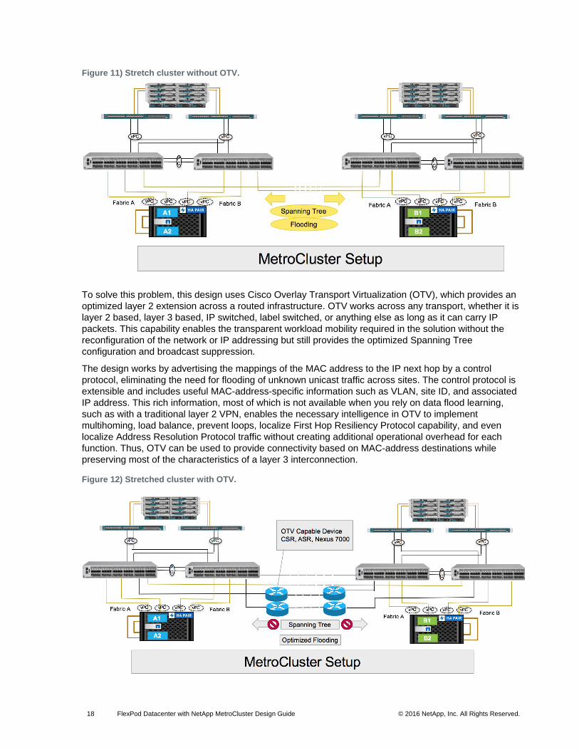
Figure 11) Stretch cluster without OTV.
To solve this problem, this design uses Cisco Overlay Transport Virtualization (OTV), which provides an
optimized layer 2 extension across a routed infrastructure. OTV works across any transport, whether it is
layer 2 based, layer 3 based, IP switched, label switched, or anything else as long as it can carry IP
packets. This capability enables the transparent workload mobility required in the solution without the
reconfiguration of the network or IP addressing but still provides the optimized Spanning Tree
configuration and broadcast suppression.
The design works by advertising the mappings of the MAC address to the IP next hop by a control
protocol, eliminating the need for flooding of unknown unicast traffic across sites. The control protocol is
extensible and includes useful MAC-address-specific information such as VLAN, site ID, and associated
IP address. This rich information, most of which is not available when you rely on data flood learning,
such as with a traditional layer 2 VPN, enables the necessary intelligence in OTV to implement
multihoming, load balance, prevent loops, localize First Hop Resiliency Protocol capability, and even
localize Address Resolution Protocol traffic without creating additional operational overhead for each
function. Thus, OTV can be used to provide connectivity based on MAC-address destinations while
preserving most of the characteristics of a layer 3 interconnection.
Figure 12) Stretched cluster with OTV.

19 FlexPod Datacenter with NetApp MetroCluster Design Guide © 2016 NetApp, Inc. All Rights Reserved.
Cisco OTV requires support on the underlying hardware. For the Data ONTAP 7-Mode FlexPod
MetroCluster design, Cisco Nexus 7000 was used as both the main data switch and the OTV end point
on each site. The FlexPod with NetApp MetroCluster design abstracts that out to a separate device to
enable greater flexibility. Cisco Nexus 9000 is used for the data switches on each site, and we took
advantage of separate Cisco Nexus 7000 series switches for the OTV feature and WAN connectivity
between sites. However, any device that supports OTV, such as the Cisco Cloud Services Router or
Aggregation Services Router, can be used and fully supported in the design. With other devices, slightly
different configurations might be required, as well as feature differences and performance characteristics.
In this multisite design, OTV enables numerous benefits in this design:
Provides layer 2 extension for ease of VM mobility (no IP address changes required)
Provides layer 2 adjacency between ESXi hosts and remote NFS datastores
Enables optimized operations such as broadcast flooding and Spanning Tree isolation
Preserves failure isolation and site independence between data centers
Is transport agnostic
For more information on OTV, see http://www.cisco.com/en/US/netsol/ns1153/index.html.
6.4 Cisco UCS (Server Types / UCS Central)
The FlexPod Datacenter with NetApp MetroCluster design supports both Cisco UCS B-Series and C-
Series servers connecting to Cisco UCS fabric interconnects. Cisco UCS supports the virtual server
environment by providing a robust, highly available, and extremely manageable compute resource. The
components of the Cisco UCS system offer physical redundancy and a set of logical structures to deliver
a very resilient FlexPod compute domain. In this validation effort, Cisco UCS B-Series servers running
ESXi are booted from SAN using iSCSI.
Cisco Unified Computing System I/O Component Selection
FlexPod allows customers to adjust the individual components of the system to meet their scale or
performance requirements. Selection of I/O components has a direct impact on scale and performance
characteristics when ordering the Cisco UCS components. Each of the two fabric extenders (I/O module)
has four 10GBASE KR (802.3ap) standardized Ethernet backplane paths available for connection to each
half-width blade slot. This means that each half-width slot has the potential to support up to 80Gb of
aggregate traffic depending on selection of:
Fabric extender model (2304, 2204XP, or 2208XP)
Modular LAN on Motherboard (mLOM) card
Mezzanine Slot card
For Cisco UCS C-Series servers, connectivity is directly to the fabric interconnect using 10Gb or 40Gb
converged adapters. Options for that connectivity include the mLOM or PCIe card.
Fabric Extender Modules
Each Cisco UCS chassis is equipped with a pair of Cisco UCS fabric extenders (FEXs). The validation
uses a Cisco UCS 2304 that has four 40GbE FCoE-capable ports that connect the blade chassis to the
fabric interconnect. Optionally, the 2208XP and 2204XP FEXs can be used for reduced bandwidth
capacity. Cisco UCS 2304 has four external QSFP ports with identical characteristics to connect to the
fabric interconnect. Each Cisco UCS 2304 has eight 40GbE ports connected through the midplane,
connecting one to each of the eight half-width slots in the chassis.
20 FlexPod Datacenter with NetApp MetroCluster Design Guide © 2016 NetApp, Inc. All Rights Reserved.
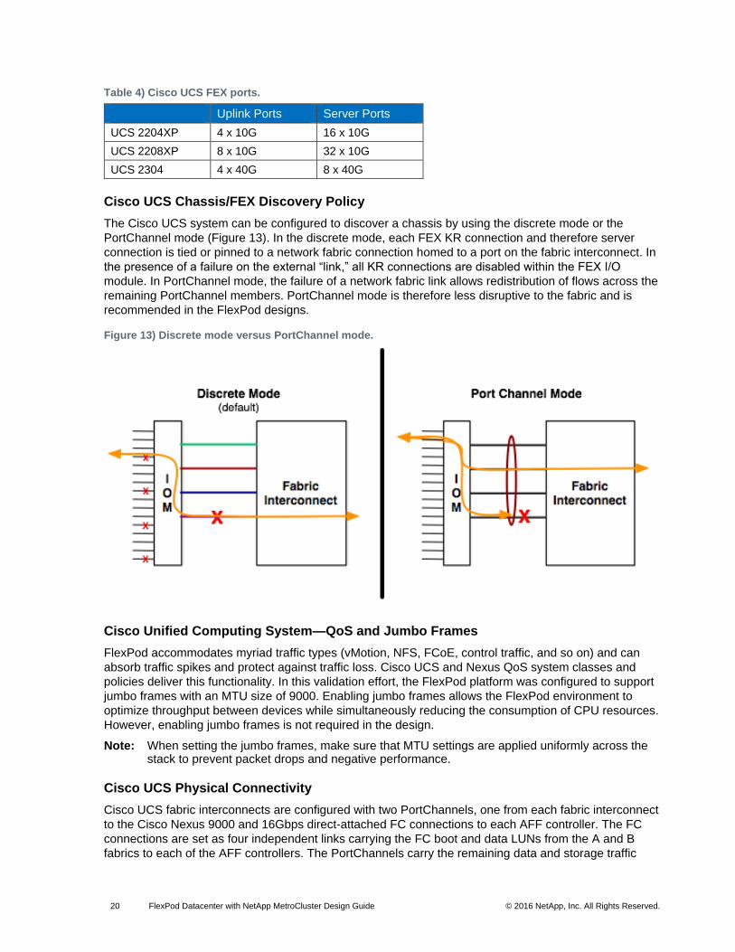
Table 4) Cisco UCS FEX ports.
Uplink Ports Server Ports
UCS 2204XP 4 x 10G 16 x 10G
UCS 2208XP 8 x 10G 32 x 10G
UCS 2304 4 x 40G 8 x 40G
Cisco UCS Chassis/FEX Discovery Policy
The Cisco UCS system can be configured to discover a chassis by using the discrete mode or the
PortChannel mode (Figure 13). In the discrete mode, each FEX KR connection and therefore server
connection is tied or pinned to a network fabric connection homed to a port on the fabric interconnect. In
the presence of a failure on the external “link,” all KR connections are disabled within the FEX I/O
module. In PortChannel mode, the failure of a network fabric link allows redistribution of flows across the
remaining PortChannel members. PortChannel mode is therefore less disruptive to the fabric and is
recommended in the FlexPod designs.
Figure 13) Discrete mode versus PortChannel mode.
Cisco Unified Computing System—QoS and Jumbo Frames
FlexPod accommodates myriad traffic types (vMotion, NFS, FCoE, control traffic, and so on) and can
absorb traffic spikes and protect against traffic loss. Cisco UCS and Nexus QoS system classes and
policies deliver this functionality. In this validation effort, the FlexPod platform was configured to support
jumbo frames with an MTU size of 9000. Enabling jumbo frames allows the FlexPod environment to
optimize throughput between devices while simultaneously reducing the consumption of CPU resources.
However, enabling jumbo frames is not required in the design.
Note: When setting the jumbo frames, make sure that MTU settings are applied uniformly across the stack to prevent packet drops and negative performance.
Cisco UCS Physical Connectivity
Cisco UCS fabric interconnects are configured with two PortChannels, one from each fabric interconnect
to the Cisco Nexus 9000 and 16Gbps direct-attached FC connections to each AFF controller. The FC
connections are set as four independent links carrying the FC boot and data LUNs from the A and B
fabrics to each of the AFF controllers. The PortChannels carry the remaining data and storage traffic

21 FlexPod Datacenter with NetApp MetroCluster Design Guide © 2016 NetApp, Inc. All Rights Reserved.
originated on the Cisco UCS. The validated design utilized two uplinks from each fabric interconnect to
the leaf switches to create the PortChannels for an aggregate bandwidth of 160GbE (4 x 40GbE). The
number of links can be easily increased based on customer data throughput requirements.
Cisco Unified Computing System—C-Series Server Design
Cisco UCS C-Series rack-mount servers are managed by the built-in standalone software, the Cisco
Integrated Management Controller (CIMC). When a C-Series rack-mount server is integrated with Cisco
UCS Manager, the CIMC does not manage the server anymore. Instead, the server is managed with the
Cisco UCS Manager software.
Cisco UCS Manager 3.1 provides three connectivity modes for Cisco UCS C-Series rack-mount server
management:
Dual-Wire Management (Shared LOM): Shared LAN on Motherboard (LOM) ports on the rack server exclusively carry management traffic. A separate cable connected to one of the ports on the PCIe card carries the data traffic. Using two separate cables for managing data traffic and management traffic is referred to as dual-wire management.
SingleConnect (Sideband): By using the Network Controller Sideband Interface, the Cisco VIC card connects one cable that can carry both data traffic and management traffic. This feature is referred to as SingleConnect.
Direct Connect Mode: This mode is an additional rack server management mode that uses direct connection (sideband) to the fabric interconnect.
For more information, see the Cisco UCS configuration guides at:
http://www.cisco.com/c/en/us/support/servers-unified-computing/ucs-manager/products-installation-and-
configuration-guides-list.html.
Cisco UCS Central
Cisco UCS Central software manages multiple globally distributed Cisco UCS domains with thousands of
servers from a single pane. Every instance of Cisco UCS Manager and all of the components managed
by it form a domain. Cisco UCS Central integrates with Cisco UCS Manager and uses it to provide global
configuration capabilities for pools, policies, and firmware. In the FlexPod with NetApp MetroCluster
design, you can use Cisco UCS Central to provide the capability to easily deploy or move the physical
servers to any of the DCs (when booting from external storage). You can do so by using the global
service profiles.
The profiles and policies defined in Cisco UCS Central can coexist with the Cisco UCS Manager–defined
information. Both Cisco UCS Manager and Cisco UCS Central manage the information defined in the
respective tool and show the information defined in the other as read-only.

22 FlexPod Datacenter with NetApp MetroCluster Design Guide © 2016 NetApp, Inc. All Rights Reserved.
Figure 14) Cisco UCS Central.
Key advantages of Cisco UCS Central:
All Cisco UCS resources, errors, and warnings from both domains are presented in a single common interface.
Various pools, service profiles, and settings are configured once, centrally.
Service profiles can be managed and deployed from a single management pane.
Service profiles (physical servers) can easily be migrated across the two Cisco UCS domains.
Cisco UCS Central is free for managing up to five Cisco UCS domains, and it is an optional component in
the FlexPod with NetApp MetroCluster design.
6.5 NetApp FAS and ONTAP
NetApp solutions offer increased availability while consuming fewer IT resources. A NetApp solution
includes hardware in the form of controllers and disk storage combined with the NetApp ONTAP software
that runs on the controllers. Two types of controllers are currently available: FAS and All Flash FAS. FAS
disk storage is offered in three configurations: serial-attached SCSI (SAS), serial ATA (SATA), and solid-
state drive (SSD). All Flash FAS systems have only SSDs.
With the NetApp portfolio, you can select the controller and disk storage configuration that best suits your
requirements. The storage efficiency built into ONTAP provides substantial space savings and allows you
to store more data at a lower cost on FAS and All Flash FAS platforms.
NetApp offers a unified storage architecture that simultaneously supports SAN, NAS, and iSCSI across
many operating environments, including VMware, Windows, and UNIX. This single architecture provides
access to data with industry-standard protocols, including NFS, CIFS, iSCSI, FC, and FCoE. Connectivity
options include standard Ethernet (10/100/1000MbE or 10GbE) and FC (4, 8, or 16Gbps).
In addition, all systems can be configured with high-performance SSD or SAS disks for primary storage
applications, low-cost SATA disks for secondary applications (such as backup and archive), or a mix of

23 FlexPod Datacenter with NetApp MetroCluster Design Guide © 2016 NetApp, Inc. All Rights Reserved.
different disk types. See the NetApp disk options available in Figure 15. Note that the All Flash FAS
configuration can support only SSDs. A hybrid cluster with a mix of All Flash FAS HA pairs and FAS HA
pairs with HDDs and/or SSDs are also supported.
Figure 15) NetApp disk options.
NetApp All Flash FAS
NetApp All Flash FAS addresses enterprise storage requirements with high performance, superior
flexibility, and best-in-class data management. Built on clustered Data ONTAP, All Flash FAS speeds up
your business without compromising on the efficiency, reliability, or flexibility of your IT operations. As true
enterprise-class all-flash arrays, these systems accelerate, manage, and protect your business-critical
data, both now and in the future. With All Flash FAS systems, you can:
Accelerate the Speed of Business
The storage operating system employs the NetApp WAFL® (Write Anywhere File Layout) system, which is natively enabled for flash media.
FlashEssentials enables consistent submillisecond latency and up to four million IOPS.
The All Flash FAS system delivers 4 to 12 times higher IOPS and 20 times faster response for databases than traditional hard-disk-drive (HDD) systems.
Reduce Costs While Simplifying Operations
High performance enables server consolidation and can reduce database licensing costs by 50%.
As the industry’s only unified all-flash storage solution that supports synchronous replication, All Flash FAS supports all your backup and recovery needs with a complete suite of integrated data-protection utilities.
Data-reduction technologies can deliver space savings of 5 to 10 times on average.
Newly enhanced inline compression delivers a near-zero performance effect. Incompressible data detection eliminates wasted cycles. Inline compression is enabled by default on all volumes in All Flash FAS running Data ONTAP 8.3.1 and later.
Always-on deduplication runs continuously in the background and provides additional space savings for use cases such as virtual desktop deployments.
24 FlexPod Datacenter with NetApp MetroCluster Design Guide © 2016 NetApp, Inc. All Rights Reserved.
Inline deduplication accelerates virtual machine (VM) provisioning.
Advanced SSD partitioning increases usable capacity by almost 20%.
Future-Proof Your Investment with Deployment Flexibility
All Flash FAS systems are ready for the data fabric. Data can move between the performance and capacity tiers on the premises or in the cloud.
All Flash FAS offers application and ecosystem integration for virtual desktop integration (VDI), database, and server virtualization.
Without silos, you can nondisruptively scale out and move workloads between flash and HDD within a cluster.
You can find more information about All Flash FAS here: http://www.netapp.com/us/products/storage-
systems/all-flash-fas.
NetApp Clustered Data ONTAP
With clustered Data ONTAP, NetApp provides enterprise-ready, unified scale-out storage. Developed
from a solid foundation of proven Data ONTAP technology and innovation, clustered Data ONTAP is the
basis for large virtualized shared storage infrastructures architected for nondisruptive operations over the
system’s lifetime. Controller nodes are deployed in HA pairs in a single storage domain or cluster.
Data ONTAP scale-out is a way to respond to growth in a storage environment. As the storage
environment grows, additional controllers are added seamlessly to the resource pool residing on a shared
storage infrastructure. Host and client connections as well as datastores can move seamlessly and
nondisruptively anywhere in the resource pool. Then, existing workloads can be easily balanced over the
available resources and new workloads can be easily deployed. Technology refreshes (replacing disk
shelves or adding or completely replacing storage controllers) are accomplished while the environment
remains online and continues serving data. Data ONTAP is the first product to offer a complete scale-out
solution, and it offers an adaptable, always-available storage infrastructure for today's highly virtualized
environment.
SAN Boot
NetApp recommends implementing SAN boot for servers in your FlexPod Datacenter platform. Doing so
enables the operating system to be safely secured by the NetApp All Flash FAS storage system,
providing better performance and fault tolerance for your infrastructure. In a disaster scenario, servers
can be redeployed on the surviving site after a MetroCluster switchover is executed, making the LUN
available on the surviving site.
In this deployment, ESXi hypervisors were booted from SAN using iSCSI. The combination of Cisco
Nexus 9000, NetApp All Flash FAS, and Cisco UCS made the iSCSI boot a simple, reliable configuration.
Each UCS server is assigned two iSCSI vNICs (one for each SAN fabric) that provide redundant
connectivity all the way to the storage. The iSCSI boot LUN is exposed to the servers through igroups
and enables only the authorized server to have access to the boot LUN.
Another method of booting from SAN that can be used is FCoE booting by connecting the NetApp All
Flash FAS storage to the Cisco UCS fabric interconnects. The storage system target WWPNs can be
zoned with the server initiator WWPNs through Cisco UCS Manager.
6.6 VMware vSphere
VMware vSphere is a virtualization platform for holistically managing large collections of infrastructure
(resources: CPUs, storage, and networking) as a seamless, versatile, and dynamic operating
environment. Unlike traditional operating systems that manage an individual machine, VMware vSphere
aggregates the infrastructure of an entire data center. Doing so creates a single powerhouse with
resources that can be allocated quickly and dynamically to any application in need.

25 FlexPod Datacenter with NetApp MetroCluster Design Guide © 2016 NetApp, Inc. All Rights Reserved.
VMware vSphere Metro Storage Cluster (vMSC)
VMware vMSC is a specific configuration of components in the VMware Hardware Compatibility List
(HCL). The configuration defines a storage cluster stretched over a large distance to maintain business
continuity. This solution is implemented with the goal of gaining the same benefits provided by high-
availability clusters to a single site to multiple geographically distinct sites. NetApp MetroCluster is a
vMSC-certified solution listed on the VMware HCL.
The “VMware vSphere Metro Storage Cluster Recommended Practices” guide defines the requirements
for configuring the following objects:
vSphere Cluster
vSphere HA
vSphere DRS
VM-to-Host Affinity Rules
The FlexPod Datacenter with NetApp MetroCluster design follows all best practices defined in the
VMware vMSC documentation. These best practices ensure that VMs are placed on the ideal site and
enable the VMware vSphere cluster to maintain business continuity by moving workloads in the event of a
compute failure.
For more information about VMware vMSC recommendations, see the VMware vSphere Metro Storage
Cluster Recommended Practices.
NFS
FlexPod Datacenter supports any SAN or NAS protocol for handling workload data traffic.
In this deployment, iSCSI SAN is used for booting the ESXi operating system and NFSv3 is used to
provide the storage necessary for the infrastructure workloads. End users can choose to use NFSv3 or
NFSv4.1 based on their requirements. The following VMware vSphere features are not supported in
NFSv4.1:
Storage DRS
Storage I/O control
Site Recovery Manager
Virtual Volumes
As part of this deployment, two NFS datastores are provisioned at each site and each datastore is
assigned a dedicated LIF with failover configured as per the best practices. A VMkernel port is created on
each ESXi server to handle all the NFS traffic. A dedicated NFS VLAN is provided between the compute
and storage to ensure a streamlined flow of data packets through the infrastructure. The NFS volumes
are exposed using export policies that define the list of approved servers that can access the underlying
file system.
7 Solution Verification
The following common failure scenarios were executed during solution verification:
Single blade failure
Host isolation
Fabric interconnect failure
Storage site isolation
Full data center isolation
Disk shelf loss
26 FlexPod Datacenter with NetApp MetroCluster Design Guide © 2016 NetApp, Inc. All Rights Reserved.
Planned switchover and switchback
Volume failure
Full storage failure in a single site
Full compute failure in a single site
Full data center failure in a single site
For detailed information about the solution verification performed for this solution, see the FlexPod
Datacenter with NetApp MetroCluster Deployment Guide.
8 Conclusion
Businesses often risk loss of revenue, employee productivity, and brand perception when key
infrastructure and services go offline. Although many of the causes of downtime can be mitigated, it is
difficult to maintain business continuity after the loss of power to an entire rack or data center. Because of
the flexibility of FlexPod Datacenter to be deployed over two sites in combination with NetApp
MetroCluster, businesses can be sure that key applications remain online—even in a large power outage.
References
This guide references the following documents and resources:
Ponemon Institute: Cost of Datacenter Outages http://www.emersonnetworkpower.com/en-US/Resources/Market/Data-Center/Latest-Thinking/Ponemon/Documents/2016-Cost-of-Data-Center-Outages-FINAL-2.pdf
NetApp All Flash FAS http://www.netapp.com/us/products/storage-systems/all-flash-fas
NetApp ONTAP http://www.netapp.com/us/products/platform-os/data-ontap-8/
Cisco Unified Computing System http://www.cisco.com/en/US/products/ps10265/index.html%20
Cisco UCS 5100 Series Blade Server Chassis http://www.cisco.com/en/US/products/ps10279/index.html%20
Cisco UCS B-Series Blade Servers http://www.cisco.com/en/US/partner/products/ps10280/index.html%20
Cisco UCS Manager http://www.cisco.com/en/US/products/ps10281/index.html%20
Cisco Nexus 9000 Series Switches http://www.cisco.com/c/en/us/products/switches/nexus-9000-series-switches/index.html
VMware vSphere https://www.vmware.com/products/vsphere
VMware vCenter Server http://www.vmware.com/products/vcenter-server/overview.html%20
Interoperability Matrices
NetApp Interoperability Matrix http://mysupport.netapp.com/matrix/#search
Cisco UCS Hardware Compatibility Matrix http://www.cisco.com/c/en/us/support/servers-unified-computing/unified-computing-system/products-technical-reference-list.html

27 FlexPod Datacenter with NetApp MetroCluster Design Guide © 2016 NetApp, Inc. All Rights Reserved.
VMware Compatibility Guide http://www.vmware.com/resources/compatibility/search.php
Version History
Version Date Document Version History
Version 1.0 September 2016 Initial version.
28 FlexPod Datacenter with NetApp MetroCluster Design Guide © 2016 NetApp, Inc. All Rights Reserved.
Refer to the Interoperability Matrix Tool (IMT) on the NetApp Support site to validate that the exact product and feature versions described in this document are supported for your specific environment. The NetApp IMT defines the product components and versions that can be used to construct configurations that are supported by NetApp. Specific results depend on each customer's installation in accordance with published specifications.
Copyright Information
Copyright © 1994–2016 NetApp, Inc. All rights reserved. Printed in the U.S. No part of this document covered by copyright may be reproduced in any form or by any means—graphic, electronic, or mechanical, including photocopying, recording, taping, or storage in an electronic retrieval system—without prior written permission of the copyright owner.
Software derived from copyrighted NetApp material is subject to the following license and disclaimer:
THIS SOFTWARE IS PROVIDED BY NETAPP "AS IS" AND WITHOUT ANY EXPRESS OR IMPLIED WARRANTIES, INCLUDING, BUT NOT LIMITED TO, THE IMPLIED WARRANTIES OF MERCHANTABILITY AND FITNESS FOR A PARTICULAR PURPOSE, WHICH ARE HEREBY DISCLAIMED. IN NO EVENT SHALL NETAPP BE LIABLE FOR ANY DIRECT, INDIRECT, INCIDENTAL, SPECIAL, EXEMPLARY, OR CONSEQUENTIAL DAMAGES (INCLUDING, BUT NOT LIMITED TO, PROCUREMENT OF SUBSTITUTE GOODS OR SERVICES; LOSS OF USE, DATA, OR PROFITS; OR BUSINESS INTERRUPTION) HOWEVER CAUSED AND ON ANY THEORY OF LIABILITY, WHETHER IN CONTRACT, STRICT LIABILITY, OR TORT (INCLUDING NEGLIGENCE OR OTHERWISE) ARISING IN ANY WAY OUT OF THE USE OF THIS SOFTWARE, EVEN IF ADVISED OF THE POSSIBILITY OF SUCH DAMAGE.
NetApp reserves the right to change any products described herein at any time, and without notice. NetApp assumes no responsibility or liability arising from the use of products described herein, except as expressly agreed to in writing by NetApp. The use or purchase of this product does not convey a license under any patent rights, trademark rights, or any other intellectual property rights of NetApp.
The product described in this manual may be protected by one or more U.S. patents, foreign patents, or pending applications.
RESTRICTED RIGHTS LEGEND: Use, duplication, or disclosure by the government is subject to restrictions as set forth in subparagraph (c)(1)(ii) of the Rights in Technical Data and Computer Software clause at DFARS 252.277-7103 (October 1988) and FAR 52-227-19 (June 1987).
ALL DESIGNS, SPECIFICATIONS, STATEMENTS, INFORMATION, AND RECOMMENDATIONS
(COLLECTIVELY, "DESIGNS") IN THIS DOCUMENT ARE PRESENTED "AS IS," WITH ALL FAULTS.
NETAPP, ALL PRODUCT VENDORS OR MANUFACTURERS IDENTIFIED OR REFERENCED HEREIN
(“PARTNERS”) AND THEIR RESPECTIVE SUPPLIERS DISCLAIM ALL WARRANTIES, INCLUDING,
WITHOUT LIMITATION, THE WARRANTY OF MERCHANTABILITY, FITNESS FOR A PARTICULAR
PURPOSE AND NONINFRINGEMENT OR ARISING FROM A COURSE OF DEALING, USAGE, OR
TRADE PRACTICE. IN NO EVENT SHALL NETAPP, ITS PARTNERS OR THEIR RESPECTIVE
SUPPLIERS BE LIABLE FOR ANY INDIRECT, SPECIAL, CONSEQUENTIAL, OR INCIDENTAL
DAMAGES, INCLUDING, WITHOUT LIMITATION, LOST PROFITS OR LOSS OR DAMAGE TO DATA
ARISING OUT OF THE USE OR INABILITY TO USE THE DESIGNS, OR WITH RESPECT TO ANY
RESULTS THAT MAY BE OBTAINED THROUGH USE OF THE DESIGNS OR RELIANCE UPON THIS
DOCUMENT, EVEN IF NETAPP, ITS PARTNERS OR THEIR RESPECTIVE SUPPLIERS HAVE BEEN
ADVISED OF THE POSSIBILITY OF SUCH DAMAGES.
THE DESIGNS ARE SUBJECT TO CHANGE WITHOUT NOTICE. USERS ARE SOLELY
RESPONSIBLE FOR THEIR APPLICATION OF THE DESIGNS AND USE OR RELIANCE UPON THIS
DOCUMENT. THE DESIGNS DO NOT CONSTITUTE THE TECHNICAL OR OTHER PROFESSIONAL
ADVICE OF NETAPP, ITS PARTNERS OR THEIR RESPECTIVE SUPPLIERS. USERS SHOULD
CONSULT THEIR OWN TECHNICAL ADVISORS BEFORE IMPLEMENTING THE DESIGNS.
RESULTS MAY VARY DEPENDING ON FACTORS NOT TESTED BY NETAPP OR ITS PARTNERS.
29 FlexPod Datacenter with NetApp MetroCluster Design Guide © 2016 NetApp, Inc. All Rights Reserved.
Trademark Information
NetApp, the NetApp logo, Go Further, Faster, AltaVault, ASUP, AutoSupport, Campaign Express, Cloud ONTAP, Clustered Data ONTAP, Customer Fitness, Data ONTAP, DataMotion, Fitness, Flash Accel, Flash Cache, Flash Pool, FlashRay, FlexArray, FlexCache, FlexClone, FlexPod, FlexScale, FlexShare, FlexVol, FPolicy, GetSuccessful, LockVault, Manage ONTAP, Mars, MetroCluster, MultiStore, NetApp Insight, OnCommand, ONTAP, ONTAPI, RAID DP, RAID-TEC, SANtricity, SecureShare, Simplicity, Simulate ONTAP, SnapCenter, Snap Creator, SnapCopy, SnapDrive, SnapIntegrator, SnapLock, SnapManager, SnapMirror, SnapMover, SnapProtect, SnapRestore, Snapshot, SnapValidator, SnapVault, StorageGRID, Tech OnTap, Unbound Cloud, WAFL, and other names are trademarks or registered trademarks of NetApp, Inc. in the United States and/or other countries. All other brands or products are trademarks or registered trademarks of their respective holders and should be treated as such. A current list of NetApp trademarks is available on the web at http://www.netapp.com/us/legal/netapptmlist.aspx. NVA-0030-DESIGN