nx cad, nx cam, nx cae, nx mold, nx …...nx mach 1 design this solution delivers all the...
TRANSCRIPT
SummaryThe NX MACH™ software products are prepackaged solutions delivering high- performance computer-aided design (CAD) capabilities of NX™ software, the leading solution for mechanical design. They offer competitively priced solutions tailored to specific product development roles, practices and processes, in four performance tiers. Value-added upgrades are available to move customers from one tier to the next. Each package delivers complete capabilities for production work.
NX MACH 1, 2 and 3 solutions include engineering process management capabili-ties for improved design team collaboration. Optional extended engineering process management tools provide scalable collabo-ration and advanced management.
All of the NX MACH design solutions share a common denominator of high-performance CAD functions and the ability to use power-ful high-definition 3D (HD3D) Visual Reporting, enabling designers and engineers to quickly understand key elements of their
www.siemens.com/nx
designs. Each level of the solutions builds upon the other, providing increasingly more sophisticated and advanced design capabilities.
NX MACH Designer This entry-level solution offers tools for creating and editing designs of typical mechanical components and assemblies, with solid modeling and drafting, basic freeform modeling and sheet metal design. It includes tools for design review, rapid prototyping, web publishing, validation checking, re-use library and custom program execution. It also offers design-oriented stress and vibration analysis wizards.
NX LayoutNX Layout is a fully integrated 2D concept design solution for NX. Built on proven NX technology, the software employs re-usable 2D components to enhance 2D concept design. Further, it can automatically create assembly structures based on 2D layouts to accelerate the detailed design phase. NX Layout provides a number of dedicated tools to support 2D design and layout, as well as 2D-to-3D capabilities.
Siemens PLM Software
NX MACH design solutionsPower, flexibility and control improve design productivity
Benefits• Boosts product design
efficiency• Accelerates mechanical
design processes• Improves collaboration• Reduces design process
waste• Improves design quality
Features• End-to-end mechanical
product design solution with a rich set of supporting tools
• High-performance modeling, drafting and comprehensive assembly design powered by synchronous technology
• Comprehensive pre-configured solutions tailored for the full range of product design applications
NX MACH 1 DesignThis solution delivers all the capabilities of NX MACH Designer, plus a managed environ-ment powered by Teamcenter® software, with data management and visualization capabilities for product and process management.
NX MACH 2 Product Design The MACH 2 Product Design package pro-vides enhanced product design capabilities, including flexible printed circuit board design, validation checking, user-defined features, rendering, 3D annotation for Product and Manufacturing Information (PMI) and basic routing.
NX Cool Shape DesignNX Cool Shape Design is a modeling-only environment delivering NX tools for fast and easy development of complex shapes. NX Cool Shape Design includes the advanced freeform tools and NX Realize Shape™ subdivision modeling.
NX MACH 3 Product DesignThe MACH 3 Product Design package provides a high-performance solution with NX design capabilities for advanced assembly design, advanced freeform modeling and surface analysis, design optimization and molded part validation.
NX MACH 3 Industrial Design MACH 3 Industrial Design delivers a broad range of NX design tools, and extends the freeform modeling capabilities with NX Realize Shape, bringing powerful subdivision modeling capabilities into the NX environment.
Enhancing basic design through productionThe NX MACH design software packages deliver comprehensive and scalable digital product development system from Siemens PLM Software that addresses all stages of the product development process, from basic design through production.
The NX MACH packages transform the product development process and support dynamic change within organizations by:
• Increasing innovation throughout the product development process
• Eliminating waste by better utilizing time, material and intellectual resources
• Improving quality from the beginning
The NX MACH design solutions offer the following advantages:
• Unified solution – seamless application integration rapidly propagates changes to product and associated process information
• Engineering process management – fully integrated, synchronized product data and process knowledge management
• Knowledge-driven automation – re-use of product and process knowledge across all elements and phases of product development
• Integrated simulation and validation – comprehensive simulation and validation tools check product performance and manufacturability throughout every step of product development
NX MACH design solutions
Features continued• Power and flexibility
that supports virtually any design methodology, whether top-down or bottom-up
• A cornerstone of a complete product development system
• Foundation for product lifecycle management
• Extendible with a selection of add-on application modules
NX
NX MACH design capabilities
Design modeling
Feature-based solid modeling The core modeling capability in NX combines wireframe, surface, solid, parametric and direct modeling in a single environment that enables designers to choose the most appro-priate tool for the task at hand. NX delivers full feature-based paramet-ric solid modeling and advanced features including blends, thin-wall, draft, mirrored features, open profile features and patterns. In addition, direct modeling with syn-chronous technology offers a fast and intuitive approach to creating and editing designs using simple push-and-pull methods, and enables you to work directly with CAD geometry created on with other systems. For greater versatility and design flexibility, you can use syn-chronous modeling interchangeably with all of the other modeling tools. A configurable, role-based user interface displays the commands you need as you need them, and grows as your experience level grows.
DesignLogic DesignLogic enables users to add design intent or knowledge as needed in the form of formulas and expressions. For example, a designer may want to drive the dimensions of a feature using a formula or mathematical expres-sion. DesignLogic allows rich control of design parameters both at creation time and during future modification.
A powerful set of associative mea-surements allows a designer to not only use measurements as a tool in sizing and locating new features in the design, but also monitor critical dimensions of a design. You can also easily add validation checks to any design parameter or associative measurement. These validation
NX
NX MACH design solutions
NX MACH
Designer
NX Layout
NX MACH 1 Design
NX MACH 2 Product Design
NX Cool
Shape Design
NX MACH 3 Product Design
NX MACH 3
Industrial Design
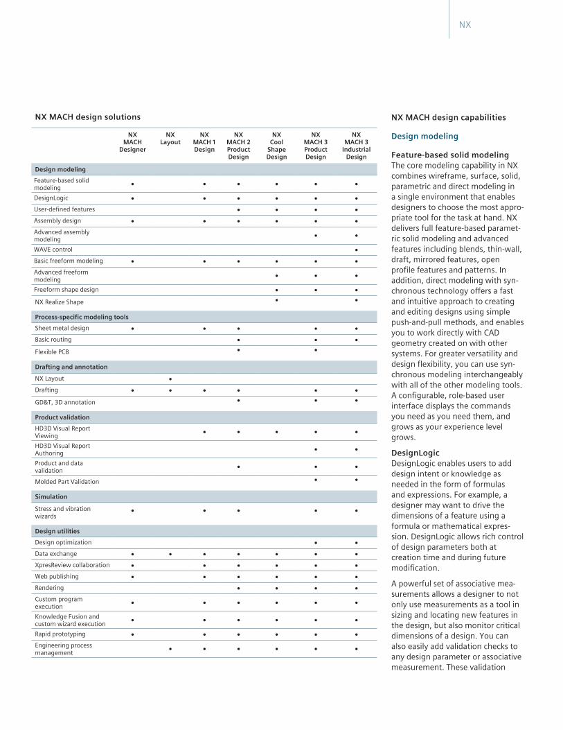
Design modelingFeature-based solid modeling • • • • • •DesignLogic • • • • • •User-defined features • • • •Assembly design • • • • • •Advanced assembly modeling • •WAVE control •Basic freeform modeling • • • • • •Advanced freeform modeling • • •Freeform shape design • • •NX Realize Shape • •
Process-specific modeling toolsSheet metal design • • • • •Basic routing • • •Flexible PCB • •
Drafting and annotation
NX Layout • Drafting • • • • • •GD&T, 3D annotation • • •
Product validationHD3D Visual Report Viewing • • • • •HD3D Visual Report Authoring • •Product and data validation • • •Molded Part Validation • •
Simulation
Stress and vibration wizards
• • • • •
Design utilitiesDesign optimization • •Data exchange • • • • • • •XpresReview collaboration • • • • • •Web publishing • • • • • •Rendering • • • •Custom program execution • • • • • •Knowledge Fusion and custom wizard execution • • • • • •Rapid prototyping • • • • • •Engineering process management • • • • • •

checks can be created on-the-fly or can be linked to external sources of design requirements, such as Microsoft Excel® spreadsheets. Validation checks help notify a designer if the value of a model expression ever strays from appropriate limits. Thus, DesignLogic helps a designer create smarter, self-checking designs that meet design requirements.
User-defined features (UDFs) Designers using NX can capture and store families of features for easy retrieval, editing and re-use. User-defined features enable designers to establish relationships between parame-ters, define feature variables, set default values and decide the general form the feature will take. Existing UDFs reside in a re-use library that is accessible by any-one using NX modeling.
The core assembly design tools in all NX MACH design solutions support design in the assembly context with navigation and inter-part relationships.
Assembly design NX assembly design supports top-down and bottom-up assembly modeling. It provides for rapid navigation of the assembly hierarchy and allows direct access to the design model of any com-ponent or subassembly. It supports the “design in context” approach where changes can be made to any component of the design model while working in the context of the assembly.
NX MACH design packages include tools for building and manipulating assembly structures. The use of inter-part relation-ships enables the creation of parametric assemblies that capture and preserve the design intent whenever changes are made.
Assemblies can be easily traversed using the assembly navigator in conjunction with intelligent component searching capabilities. NX assemblies also include support for the creation of flexible assemblies and parts, enabling different arrangements and configurations of components such as springs and pistons.
Advanced assembly modelingThe advanced assembly modeling capabilities in MACH 3 packages enable you to simplify components or subas-semblies into a single lightweight solid, to enclose assembly geometry in an envelope of planar faces, to partition assemblies into meaningful regions,
and to manage weight and other mass properties of components and assem-blies. Component filtering techniques allow users to quickly identify and load the components of relevance to their current task, avoiding unnecessary delays and screen clutter caused by loading irrelevant components.
Assembly enveloping techniques enable the user to represent major subassem-blies as simplified abstractions to further reduce assembly load times and avoid the display of unwanted or proprietary interior detail. The sophisticated clear-ance analysis and weight management tools provided in advanced assemblies are also optimized for analyzing poten-tial problems with fit, clearance and mass properties.
Active mockupA complete digital mockup capability extends the toolset for building, editing and evaluating assembly models. It is especially useful when working with large assemblies, but also helps improve the productivity of most users who work regularly in an assembly context. Active mockup makes use of the standard, CAD-neutral, lightweight JT™ data for-mat. This improves the performance and memory efficiency of loading and designing in the context of massive assemblies.
Synchronous technology in NX Design solutions combines the best of both parametric and direct modeling.
NX
Active mockup enables design in the full assembly context, even with multi-CAD data.
WAVE controlNX WAVE is a geometry linking tool that enables designers to define interpart relationships for parametric assembly modeling. WAVE assembly control struc-tures and constraints help simplify design changes and accelerate modeling of configurations, options and variants.
Basic freeform modeling Basic freeform modeling in NX provides tools for creating complex surface and solid models. Capabilities include:
• Creating solids from sheets• Basic sweeping along curves• Proportionally developed shapes
using 1-, 2- and 3-rail methods• Lofting – ruled, curve mesh, lofted
shapes using standard conic methods and meshes of points and curves
• Special surface creation – surface extension and n-sided, bounded plane offset
• Surface manipulation tools – surface extension and surface normal control
• Body-based trimming• Surface trimming using curves
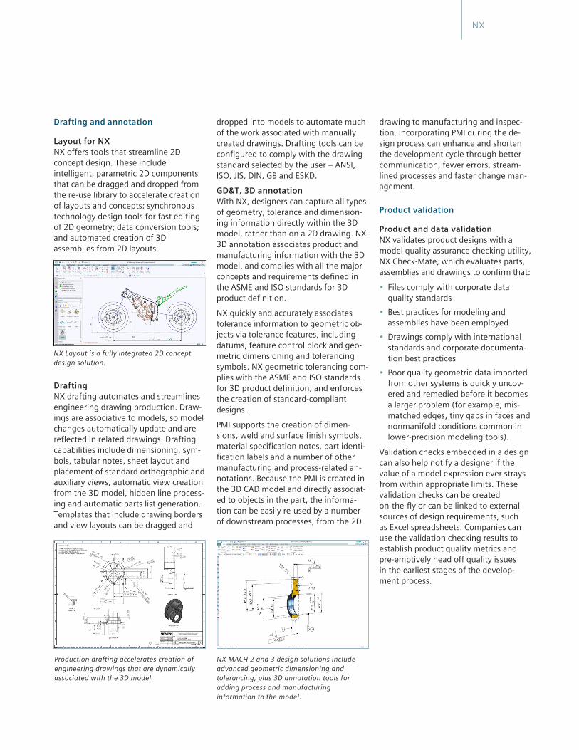
NX Realize Shape delivers fast, intuitive subdivision modeling technology for more efficient design of complex shapes.
Advanced freeform modeling Advanced freeform modeling extends the toolset to include complex filleting, blends and transition surfaces. Guided assistance accelerates the creation of solids from sheets, and the software also helps create surfaces from external point, pole and point cloud data.
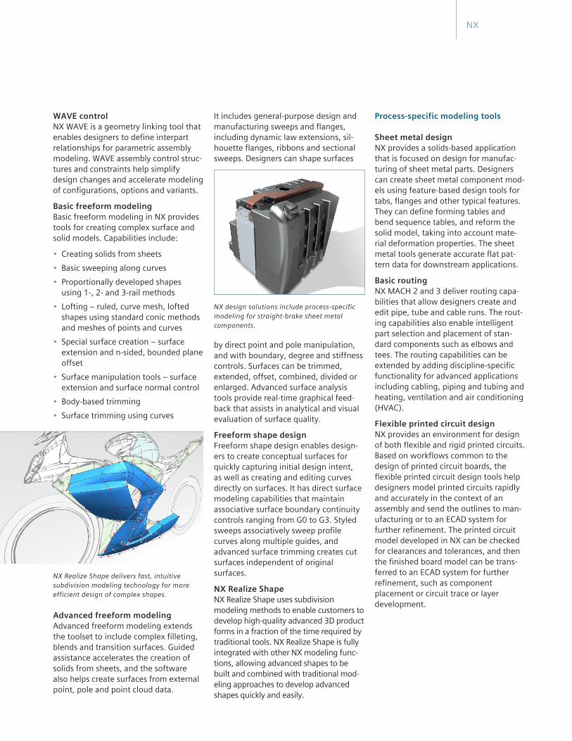
It includes general-purpose design and manufacturing sweeps and flanges, including dynamic law extensions, sil-houette flanges, ribbons and sectional sweeps. Designers can shape surfaces
NX design solutions include process-specific modeling for straight-brake sheet metal components.
by direct point and pole manipulation, and with boundary, degree and stiffness controls. Surfaces can be trimmed, extended, offset, combined, divided or enlarged. Advanced surface analysis tools provide real-time graphical feed-back that assists in analytical and visual evaluation of surface quality.
Freeform shape design Freeform shape design enables design-ers to create conceptual surfaces for quickly capturing initial design intent, as well as creating and editing curves directly on surfaces. It has direct surface modeling capabilities that maintain associative surface boundary continuity controls ranging from G0 to G3. Styled sweeps associatively sweep profile curves along multiple guides, and advanced surface trimming creates cut surfaces independent of original surfaces.
NX Realize ShapeNX Realize Shape uses subdivision modeling methods to enable customers to develop high-quality advanced 3D product forms in a fraction of the time required by traditional tools. NX Realize Shape is fully integrated with other NX modeling func-tions, allowing advanced shapes to be built and combined with traditional mod-eling approaches to develop advanced shapes quickly and easily.
Process-specific modeling tools
Sheet metal design NX provides a solids-based application that is focused on design for manufac-turing of sheet metal parts. Designers can create sheet metal component mod-els using feature-based design tools for tabs, flanges and other typical features. They can define forming tables and bend sequence tables, and reform the solid model, taking into account mate-rial deformation properties. The sheet metal tools generate accurate flat pat-tern data for downstream applications.
Basic routingNX MACH 2 and 3 deliver routing capa-bilities that allow designers create and edit pipe, tube and cable runs. The rout-ing capabilities also enable intelligent part selection and placement of stan-dard components such as elbows and tees. The routing capabilities can be extended by adding discipline-specific functionality for advanced applications including cabling, piping and tubing and heating, ventilation and air conditioning (HVAC).
Flexible printed circuit design NX provides an environment for design of both flexible and rigid printed circuits. Based on workflows common to the design of printed circuit boards, the flexible printed circuit design tools help designers model printed circuits rapidly and accurately in the context of an assembly and send the outlines to man-ufacturing or to an ECAD system for further refinement. The printed circuit model developed in NX can be checked for clearances and tolerances, and then the finished board model can be trans-ferred to an ECAD system for further refinement, such as component placement or circuit trace or layer development.
NX
dropped into models to automate much of the work associated with manually created drawings. Drafting tools can be configured to comply with the drawing standard selected by the user – ANSI, ISO, JIS, DIN, GB and ESKD.
GD&T, 3D annotation With NX, designers can capture all types of geometry, tolerance and dimension-ing information directly within the 3D model, rather than on a 2D drawing. NX 3D annotation associates product and manufacturing information with the 3D model, and complies with all the major concepts and requirements defined in the ASME and ISO standards for 3D product definition.
NX quickly and accurately associates tolerance information to geometric ob-jects via tolerance features, including datums, feature control block and geo-metric dimensioning and tolerancing symbols. NX geometric tolerancing com-plies with the ASME and ISO standards for 3D product definition, and enforces the creation of standard-compliant designs.
PMI supports the creation of dimen-sions, weld and surface finish symbols, material specification notes, part identi-fication labels and a number of other manufacturing and process-related an-notations. Because the PMI is created in the 3D CAD model and directly associat-ed to objects in the part, the informa-tion can be easily re-used by a number of downstream processes, from the 2D
drawing to manufacturing and inspec-tion. Incorporating PMI during the de-sign process can enhance and shorten the development cycle through better communication, fewer errors, stream-lined processes and faster change man-agement.
Product validation
Product and data validation NX validates product designs with a model quality assurance checking utility, NX Check-Mate, which evaluates parts, assemblies and drawings to confirm that:
• Files comply with corporate data quality standards
• Best practices for modeling and assemblies have been employed
• Drawings comply with international standards and corporate documenta-tion best practices
• Poor quality geometric data imported from other systems is quickly uncov-ered and remedied before it becomes a larger problem (for example, mis-matched edges, tiny gaps in faces and nonmanifold conditions common in lower-precision modeling tools).
Validation checks embedded in a design can also help notify a designer if the value of a model expression ever strays from within appropriate limits. These validation checks can be created on-the-fly or can be linked to external sources of design requirements, such as Excel spreadsheets. Companies can use the validation checking results to establish product quality metrics and pre-emptively head off quality issues in the earliest stages of the develop-ment process.
NX
Drafting and annotation
Layout for NXNX offers tools that streamline 2D concept design. These include intelligent, parametric 2D components that can be dragged and dropped from the re-use library to accelerate creation of layouts and concepts; synchronous technology design tools for fast editing of 2D geometry; data conversion tools; and automated creation of 3D assemblies from 2D layouts.
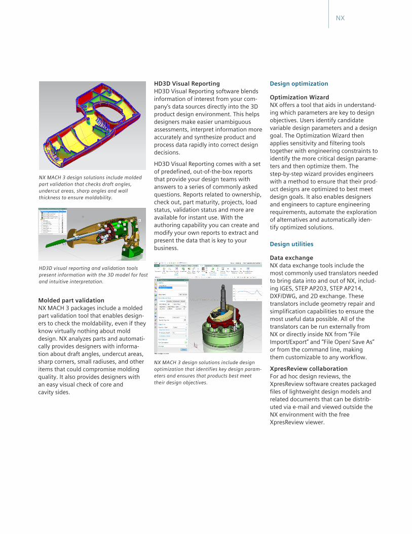
NX Layout is a fully integrated 2D concept design solution.
Drafting NX drafting automates and streamlines engineering drawing production. Draw-ings are associative to models, so model changes automatically update and are reflected in related drawings. Drafting capabilities include dimensioning, sym-bols, tabular notes, sheet layout and placement of standard orthographic and auxiliary views, automatic view creation from the 3D model, hidden line process-ing and automatic parts list generation. Templates that include drawing borders and view layouts can be dragged and
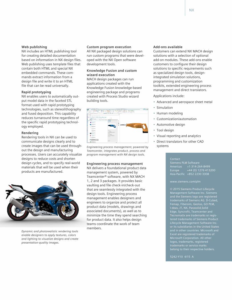
Production drafting accelerates creation ofengineering drawings that are dynamicallyassociated with the 3D model.
NX MACH 2 and 3 design solutions include advanced geometric dimensioning and tolerancing, plus 3D annotation tools for adding process and manufacturing information to the model.
Molded part validationNX MACH 3 packages include a molded part validation tool that enables design-ers to check the moldability, even if they know virtually nothing about mold design. NX analyzes parts and automati-cally provides designers with informa-tion about draft angles, undercut areas, sharp corners, small radiuses, and other items that could compromise molding quality. It also provides designers with an easy visual check of core and cavity sides.
HD3D Visual Reporting HD3D Visual Reporting software blends information of interest from your com-pany’s data sources directly into the 3D product design environment. This helps designers make easier unambiguous assessments, interpret information more accurately and synthesize product and process data rapidly into correct design decisions.
HD3D Visual Reporting comes with a set of predefined, out-of-the-box reports that provide your design teams with answers to a series of commonly asked questions. Reports related to ownership, check out, part maturity, projects, load status, validation status and more are available for instant use. With the authoring capability you can create and modify your own reports to extract and present the data that is key to your business.
NX MACH 3 design solutions include designoptimization that identifies key design param-eters and ensures that products best meet their design objectives.
Design optimization
Optimization WizardNX offers a tool that aids in understand-ing which parameters are key to design objectives. Users identify candidate variable design parameters and a design goal. The Optimization Wizard then applies sensitivity and filtering tools together with engineering constraints to identify the more critical design parame-ters and then optimize them. The step-by-step wizard provides engineers with a method to ensure that their prod-uct designs are optimized to best meet design goals. It also enables designers and engineers to capture engineering requirements, automate the exploration of alternatives and automatically iden-tify optimized solutions.
Design utilities
Data exchange NX data exchange tools include the most commonly used translators needed to bring data into and out of NX, includ-ing IGES, STEP AP203, STEP AP214, DXF/DWG, and 2D exchange. These translators include geometry repair and simplification capabilities to ensure the most useful data possible. All of the translators can be run externally from NX or directly inside NX from “File Import/Export” and “File Open/ Save As” or from the command line, making them customizable to any workflow.
XpresReview collaboration For ad hoc design reviews, the XpresReview software creates packaged files of lightweight design models and related documents that can be distrib-uted via e-mail and viewed outside the NX environment with the free XpresReview viewer.
NX
HD3D visual reporting and validation tools present information with the 3D model for fast and intuitive interpretation.
NX MACH 3 design solutions include molded part validation that checks draft angles, undercut areas, sharp angles and wall thickness to ensure moldability.
Web publishing NX includes an HTML publishing tool for creating detailed documentation based on information in NX design files. Web publishing uses template files that contain both HTML and special NX embedded commands. These com-mands extract information from a design file and write it to an HTML file that can be read universally.
Rapid prototyping NX enables users to automatically out-put model data in the faceted STL format used with rapid prototyping technologies, such as stereolithography and fused deposition. This capability reduces turnaround time regardless of the specific rapid prototyping technol-ogy employed.
Rendering Rendering tools in NX can be used to communicate designs clearly and to create images that can be used through-out the design and manufacturing processes. Users can accurately visualize designs to reduce costs and shorten design cycles, and to specify real-world materials that will be used when their products are manufactured.
Custom program execution All NX packaged design solutions can run custom programs that were devel-oped with the NX Open software development tools.
Knowledge Fusion and custom wizard execution MACH design packages can run applications created with the Knowledge Fusion knowledge-based engineering package and programs created with Process Studio wizard building tools.
Engineering process management, powered by Teamcenter, integrates product, process and program management with NX design tools.
Engineering process management NX delivers a foundational product data management system, powered by Teamcenter® software, with NX MACH 1, 2 and 3 packages. It provides basic vaulting and file check-in/check-out that are seamlessly integrated with the design tools. Engineering process management enables designers and engineers to organize and protect all product data (models, drawings and associated documents), as well as to minimize the time they spend searching for product data. It also helps design teams coordinate the work of team members.
Add-ons availableCustomers can extend NX MACH design solutions with a selection of optional add-on modules. These add-ons enable customers to configure their design solutions to specific requirements such as specialized design tools, design- integrated simulation solutions, programming and customization toolkits, extended engineering process management and direct translators.
Applications include:
• Advanced and aerospace sheet metal• Simulation• Human modeling• Customization/automation• Automotive design• Tool design• Visual reporting and analytics• Direct translators for other CAD
systems
NX
ContactSiemens PLM SoftwareAmericas +1 314-264-8499 Europe +44 (0) 1276 413200 Asia-Pacific +852 2230 3308
www.siemens.com/plm
© 2015 Siemens Product Lifecycle Management Software Inc. Siemens and the Siemens logo are registered trademarks of Siemens AG. D-Cubed, Femap, Fibersim, Geolus, GO PLM, I-deas, JT, NX, Parasolid,Solid Edge, Syncrofit, Teamcenter and Tecnomatix are trademarks or regis-tered trademarks of Siemens Product Lifecycle Management Software Inc. or its subsidiaries in the United States and in other countries. Microsoft and Excel are registered trademarks of Microsoft Corporation. All other logos, trademarks, registered trademarks or service marks belong to their respective holders. 5242-Y10 4/15 A
Dynamic and photorealistic rendering tools enable designers to apply textures, colors and lighting to visualize designs and create presentation-quality images.