nx helmet exercise guide.1 - amazon s3 · 2018-09-25 · siemens nx helmet exercise guide ... nx...
TRANSCRIPT

SIEMENS NX HELMET EXERCISE GUIDE
Sketching in NX using 2D Synchronous Technology ........................................................................................................................... 1
Creating an assembly drawing with PMI in NX ................................................................................................................................ 14
Creating an aesthetic shape using the freeform modeling tools in NX ............................................................................................ 20
Rendering and Visualization using NX Ray Traced Studio ................................................................................................................ 33
Version(s) supported: NX 12.X

1
SketchinginNXusing2DSynchronousTechnologyIntroductionSynchronous Technology in NX makes sketching and modeling fast and intuitive and gives the user the freedom to modify geometry using simple push-and-pull methods. This tutorial shows you how to work with an imported sketch, make modifications to the sketch and use the sketch for adding features to the geometry.
1 To start, open C://data_sketch/Helmet_electro.prt
The model used for this tutorial is “Helmet_electro.prt”
2 In the Assembly Navigator, select sub-assembly “speaker_L” à right-mouse button à select ‘Open in Window’

2
3 In the Assembly Navigator à double-click à “ yoke” to make it the Work Part
4 Go to the Top Border bar à click Show and Hide à Click + à Click Close

3
Note: These are imported curves that have some errors and do not have any constraints. It highlights a common problem where translated geometry will have integrity issues, such as gaps, overlaps, non-tangencies, or curves that should be on the same plane but are not. Synchronous Technology 2D in NX enables users to quickly fix these issues, as well as make changes to these curves without the need for constraints.
5 Go to the Home tab and click Sketch.

4
Select the top planar face of the coil as sketch plane à click OK (close the dialog)
Note: Turn off “Create inferred constrains” and “Continuous Auto Dimensioning” from the Home tab. Since we will be using Synchronous Technology 2D to make changes to this profile, we don’t want to deal with constraints, since they are not necessary and will save us quite a bit of time.

5
6 Choose Add Existing Curves from the Home tab
Select the imported curves à by dragging a box across the entire profile à Click OK
Note: The Optimize 2D Curve command cleans up and simplifies imported geometry and points. For example, it will eliminate duplicate curves, close gaps (snap curves to their endpoints), simplify curve types (convert B-curves into analytic), move all curves to the sketch plane, and so on. It is a very valuable tool for quickly cleaning up imported and legacy data.
7 On the Home tab à click Optimize 2D Curve

6
Drag a box à select all curves à click OK
Note: Hold down the middle mouse buton to rotate the model, if needed. On the keyboard, use Shift+F8 keys to orient the view back to the plane of the sketch.
The Top Border bar has many filtering, selection and view manipulation options.
8 Click Expand button à see the rest of the Sketch Curve commands

7
Choose the Mirror Curve command
Drag a box to select all curves.
In the Mirror Curve dialogue window à click on Select Centerline à Click on the X axis (in the graphics window) à click Apply
Keep the Mirror Curve dialogue window open

8
9 Repeat the above procedure à select both profiles by dragging a box to mirror them about the Y axis à Click OK
Note: Even though there are no constraints in this sketck, Synchronous Technology 2D finds geometric relations based on the curve(s) you select to edit and maintains these relations during

9
change. Synchronous Technology 2D commands make it possible to make dynamic modifications to sketches while maintaining tangency constraints and connectivity.
10 Choose Move Curve from the Home tab
Select the upper arc of the profile on the top à right side of the sketch.
Click on the ball in the center of the translation widget (called Orient Express) à drag the center of the translation widget to snap it to the sketch origin
Expand Curve Finder à go to the Setting tab and turn on Select Symmetric.

10
Enter 30 for the Angle à click Apply.
11 While the Move Curve command is still active à select the lower arc à drag and snap Orient Express to the sketch origin (same as in the previous step) à enter 7 for the Angle à click OK.
Note: Sketches modified with Synchronous Technology 2D are automatically updated according to changes in real-time. For instance, if you move or offset a curve, all associated geometry intelligently adapts. The relevant relationships are preserved while irrelevant relationships are removed to enable the intended change to be made with ease.

11
12 While the Sketch is still active à click Extrude on the Home tab
Rotate the view so the preview of the extrusion is better seen
The extrusion direction is chosen by default and should be along the positive Z axis. We want it to go in the opposite direction. Click on the Reverse Direction icon in the Direction group on the dialog.
Specify start and end limit for the extrusion. We will use a value for the start of the extrusion, and a trimming condition for the end.
Start = - 0.6
End = Until Next
Set Boolean= Unite and click OK

12
Design is completed
Double click speaker_L
Select Helmet_electro.prt Tab

13
13 Go to File à Close à All Parts to return to the Tutorial Home page. Click “No – Close” in the Close All Files message window.
Endofactivity

14
CreatinganassemblydrawingwithPMIinNXIntroductionThere is a growing need to document designs in 3D in support of the Model Based Definition (MBD) initiative many companies have or are undertaking. Working with 2D legacy data involves significant manual the effort of recreating information from a drawing onto the 3D model. To simplify and automate these workflows, NX has tools such as ‘Convert to PMI’ to automatically convert drawing views and objects to model views and PMI objects.
This tutorial walks you through the process of creating an assembly drawing sheet, adding exploded view to the drawing and generating a parts list for the drawing sheet. We will then add GD&T symbols to the drawing and automatically generate PMI using the ‘Convert to PMI’ feature.
1 The model used for this tutorial is ‘Helmet asm.prt’
Note: We have already created a drawing and placed a couple of views in order to accelerate the workflow for the purposes of this test drive. This review does not use NX “Master Mondel Concept” where drawing is in a separate file from the model (or assembly file).
2 In the Part Navigator à expand Drawing à double-click “Sheet 1” to open it
There are two existing views.

15
Note: The objective of the next few steps is to demonstrate how you can add an exploded assembly view to a drawing and automatically create baloons and the corresponding table, and make manual adjustments if necessary.
3 Home tab à click Base View
Under Model View to Use à set Model View to Use to Exploded
Place it on the right side of the sheet next to the two existing views Click Close

16
4 Home tab à click Parts List. Place it next to the exploded view.
5 Home tab à click Auto Balloon
Select the parts-list à click OK Parts List Auto Balloon window à select the exploded view à click OK
The position of the balloons can be changed by dragging them.
Note: The objective of the next few steps is to add annotations to a drawing. Although these are just a few basic types, you will be able to get a feel for the UI and interaction in performing this task.

17
6 Home tab à click Datum Target
Click and hold on a point towards the front of the helmet. Drag to an appropriate location and place it. Add two more datums along the same curve; one in the middle and the second towards the bottom. (See the next image in Step 7). Click Close
7 Home tab à click Feature Control Frame
Expand Frame, set the Characteristic to Profile of a Surface. Under Tolerance, enter a value of 0.1 and set the Primary Datum Reference to A.

18
Click and hold on a point and drag to an appropriate location and place it. Click Close
8 Drafting Tool tab à click Convert to PMI
Under Type select View à From the Views List à select “ORTHO@6” à click OK.
Note: Lastly, we can now convert the annotation in a drawing view to PMI objects in 3D. You have options to convert a single view, multiple views, or the entire drawing including multiple sheets.

19
9 On the Application tab, click Modeling. In the Part Navigator, expand Model Views and double-click “Right”.
The PMI objects added to the drawing sheet are now associated with the 3D model making it easier to access critical product information and enabling a model-based definition workflow.
10 Go to File à Close à All Parts to return to the Tutorial Home page. Click “No – Close” in the Close All Files message window.
Endofactivity

20
CreatinganaestheticshapeusingNXRealizeShape(FreeFormTool)inNXIntroductionFairly often the design of a product calls for creation of a more freeform shape. Conventional tools require a high level of expertise and still can take more than desired time to create. NX offers a product called Realize Shape that is based on the subdivision technique which enables designers to create complex shapes in a fraction of the time compared to conventional tools. Equally important is the ability to use all NX commands on the resultant geometry in order to add the required details that tend to be more mechanical and require traditional construction methods and tools.
NX Realize Shape provides an intuitive approach to sculpt 3D solid or sheet bodies by manipulating and subdividing a control cage. In this tutorial, we begin by using a raster image of a conceptual sketch to create a primitive shape that is transformed into an organic shape. We will then use this shape to modify the helmet shell and finally, add a logo to the helmet.
1 The model used for this tutorial is “Helmet_SubD_Replaceface_Emboss.prt”
Top Border bar à click Show and Hide à Click “–“ under Hide for Solid Bodies à Click Close.

21
This would display just the raster image to be used for creating the shape.
Note: The design typically starts with a primitive shape. NX offers a number of shapes like a sphere, a block, a cylinder, and others. For this activity a block is the most suitable shape to start with.
2 Surface tab à click NX Realize Shape.
On the Home tab à click Primitive Shape
Set the Type as Block à Enter these values for the Size:

22
Length = 68 mm
Width = 100 mm
Height = 48 mm
Click on the origin in the graphics window and enter these values:
X = 0
Y = 58
Z = 10
Click OK
Note: A bicycle helmet typically has a freeform and organic shape. The cutouts at the back of the helmet were designed to match the theme of the overall design, and the shape of the tool required to make these cutouts is also freeform. This is a a good example of how Realize Shape can be effectively used to quickly create a somewhat complex shape. Using conventional tools for modeling this shape will take significantly longer and may requie advanced surfacing skills. Realize Shape creates high quality geometry with natural continuity between faces.
3 On the Home tab à click Transform Cage
Under Method à click on the Transform tab à check Reorient Tool to Selection
Select the two parallel edges along X axis and drag them using the sphere to align with the raster image.

23
Click Apply.
4 Select the vertical edge à drag it towards the raster image using the Y Translate grab handle.
Click OK à to close the Transform Cage window.

24
5 Home tab à click Start Symmetric Modeling.
Select the Y-Z plane and click OK.
Note: In order to to achieve the desired shape, we split the faces of the original primitive shape. This gives us the ablility to edit the shape locally and add more details.
6 Home tab à click Split Face
Select the four highlighted faces (front, back, top, and bottom).
Click on Select Reference Edge à select the horizontal edge on the top of the back face to split the four faces
Click OK.

25
7 Home tab à click Transform Cage
Select outside face to transform à click on the YZ Rotate handle à Enter
Angle = 9 (if the rotation moves in the wrong direction, change value to -9)
Drag outside face to match the image
Click OK
8 Home tab à click Split Face
Select the five faces (two each in the front and back, one on the side) to split and the vertical edge as the reference.
Click OK
26
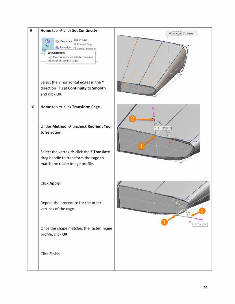
9 Home tab à click Set Continuity
Select the 7 horizontal edges in the Y direction à set Continuity to Smooth and click OK
10 Home tab à click Transform Cage
Under Method à uncheck Reorient Tool to Selection.
Select the vertex à click the Z Translate drag handle to transform the cage to match the raster image profile.
Click Apply.
Repeat the procedure for the other vertices of the cage.
Once the shape matches the raster image profile, click OK.
Click Finish.

27
Note: Now that we have finished designing the initial shape of the tool which we will use to make the cutouts in the back of the helmet, we can use more conventional design tools to finish the required model. Since subdivision modeling is part of the core modeling environment in NX, you are able to seamlessly use all of the modeling tools in NX to add to the subdivision body.
For the purposes of this test drive we have already created the second subdivision model which we will now use to remove the required material from the body we just designed.
11 Go to the Top Border bar à click Show and Hide à Click – under Hide for Raster Images. Click Close.
In the Part Navigator à right-click on Subdivision Body (10) à select Show.
13 Go to the Home tab à Feature group à Subtract.
Select Subdivision Body (13) as the Target à Subdivision Body (10) as the Tool.
Click OK.

28
Note: In the next few steps we will use the tool body we made in order to create the required cutout in a couple of parts in the back of the helmet.
14 In the Part Navigator à right-click on Body (2) “ENGRAVING” à select Show.
Similarly à right-click on Body (7) “INNERLAYR “à select Show.
15 Go to the Home tab à Feature group à Subtract.
Select Body (2) “ENGRAVING” as the Target à Subdivision Body (13) as the Tool.
Under Settings à check Keep Tool.
Click Apply.
16 In the Subtract window, select Body (7) “INNERLAYR “as the Target à Subdivision Body (13) as the Tool.
Under Settings à uncheck Keep Tool.
Click OK.

29
Note: In the next steps you will be able to experience how NX can help solve another interesting design challenge. Many times a design will call for an emossed or indented shape. We took an NX font and converted it to curves, which is one of the commands in NX. Now in a few simple steps we will use these curves to create a solid body and use it to emboss the helmet geometry.
17 In the Part Navigator à right-click on Body (7) “INNERLAYR” à select Hide.
Right-click on Text (9) à select Show.
18 On the Home tab, select Extrude from the Feature group.
For Select Curve à click on the text.
Under Direction, click Reverse Direction
.
Enter Start = 0 à End = 15 and Boolean = None
Click OK.

30
19 On the Home tab, Synchronous Modeling group, select Replace Face.
For Select Face à select the face of letter N closer to the helmet
For Replacement Face à select the two faces of the helmet.
For Offset à click on Reverse Direction (blue arrow pointing towards the helmet) and enter Distance = 1.
Click Apply.
20 Repeat the procedure in the previous step for letter X and select the three faces.
Click OK.

31
21 On the Home tab à click Emboss Body.
Select Body (2) “ENGRAVING” as the Target and “N” as the Tool.
Enter Thickness = 1.5
Click Apply.
22 Repeat the procedure in the previous step for letter X à change
Thickness = 1.6
Click OK.
23 In the Part Navigator à right-click on Text (9) à select Hide.
In the Part Navigator à Ctrl select the two Emboss Body features in the tree and go to Assign Feature Color.
Under Feature Face Color, click on Specify Color and select a color.

32
24 On the View tab à click on Edit Section to verify that the depth of the emboss is uniform.
Click Cancel.
25 Go to the Top Border bar à click Show and Hide à Click on + under Show for Solid Bodies.
Click Close.
26 Go to File à Close à All Parts to return to the Tutorial Home page à Click “No – Close” in the Close All Files message window.
Endofactivity
33
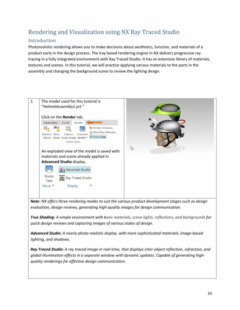
RenderingandVisualizationusingNXRayTracedStudioIntroductionPhotorealistic rendering allows you to make decisions about aesthetics, function, and materials of a product early in the design process. The Iray based rendering engine in NX delivers progressive ray tracing in a fully integrated environment with Ray Traced Studio. It has an extensive library of materials, textures and scenes. In this tutorial, we will practice applying various materials to the parts in the assembly and changing the background scene to review the lighting design.
1 The model used for this tutorial is “HelmetAssembly2.prt “ Click on the Render tab.
An exploded view of the model is saved with materials and scene already applied in Advanced Studio display.
Note: NX offers three rendering modes to suit the various product development stages such as design evaluation, design reviews, generating high-quality images for design communication.
True Shading: A simple environment with basic materials, scene lights, reflections, and backgrounds for quick design reviews and capturing images of various states of design.
Advanced Studio: A nearly photo-realistic display, with more sophisticated materials, image-based lighting, and shadows.
Ray Traced Studio: A ray traced image in real-time, that displays inter-object reflection, refraction, and global illumination effects in a separate window with dynamic updates. Capable of generating high-quality renderings for effective design communication.

34
2 Assemblies Tab à Exploded Views dropdown à select No Explosion
3 On the Render tab à select Ray Traced Studio
The rendering starts as soon as the Ray Traced Studio window is displayed.
Pause the rendering in the Ray Traced Studio window after a few iterations.
Tile the two windows such that the model and the rendering can be visualized side-by-side.
Note: The Ray Traced Studio window menu gives you the ability to pause and restart the rendering process until you are satisfied with the rendered result. It has three render modes that lets you choose the level of interactivity and performance.

35
Photoreal: Uses a physically-based, path-tracing render mode that generates photorealistic imagery with full global illumination effects.
Quality Interactive: Uses an interactive raytracing render mode optimized to give the best approximation of Photoreal with increased interactivity.
Fast Interactive: Uses an interactive raytracing render mode optimized for the fastest view dynamic performance.
4 On the Render tab à click Materials in Part
The Studio Materials in Part are displayed.
Drag/drop TopVisorPlasticBlue (Coated) from the materials palette to the neon green Visor in the graphics window.
Repeat the procedure for the Top panels of the outer helmet shell.
Click Start/Resume in the Ray Traced Studio window.
5 Drag/drop SidesBackPlasticPearlescentNeonGreen to

36
the black Side and Back panels of the helmet shell
Note: The Studio Materials in Part palette shows the materials that have been used in the model. NX comes with a broad, pre-defined set of materials that can be accessed from System Studio Materials. These are customizable materials based on NVIDIA Material Definition Language (MDL) that support advanced material characteristics such as light emission.
6 Go to System Scenes on the Resource Bar.
In the Studio folder, select Black Studio Scene 1.
Note: System Scenes in NX consist of indoor and outdoor scenes that have pre-defined background, stage, reflection, shadow, and global illumination attributes. Applying a visualization scene to your model to puts it into visual context. Existing System Scenes can be edited to make further changes to your background, scenes, lighting, and reflection, if necessary.
7 Adjust the Brightness using the slider located at the bottom of the Ray Traced Studio window.
Drag the Brightness slider to the right to brighten the scene.
Click Pause after a few iterations in the Ray Traced Studio window.

37
8 Go to File à Close à All Parts to return to the Tutorial Home page. Click “No – Close” in the Close All Files message window.
Endofactivity