nx-series analog input unit nx-ad - omron polskaomronpliki.pl/instrukcje/sysmac nj/materialy/karty...
TRANSCRIPT

CSM_NX-AD_DS_E_1_1
1
NX-series Analog Input Unit
NX-ADAnalog Inputs to meet all machine control needs; from general-purpose inputs to high-speed synchronous, high-resolution units
• Analog Input Units for the NX-series modular I/O system.• Connect to other NX-series I/O Units and EtherCAT
Coupler units using the high-speed NX-bus.• Separate modules for voltage- and current inputs.
Features• Up to eight analog inputs per unit.• Free-run refreshing or synchronous I/O refreshing can be selected using the NX-series EtherCAT Coupler.• Input update cycles of 10μs per channel, and a resolution of 1/30000, ideal for high-speed measurement and, high-precision control.• All basic models are available as single-ended and differential-input types.• The screwless terminal block is detachable for easy commissioning and maintenance.• Screwless push-in terminal block significantly reduces wiring work.• All models are just 12 mm wide, saving space in your cabinet.
System Configuration
* OMRON CJ1W-NC@81/@82 Position Control Units cannot be connected to the EtherCAT Slave Terminal even though they support EtherCAT.
Sysmac® is a trademark or registered trademark of OMRON Corporation in Japan and other countries for OMRON factory automation products.EtherCAT® is a registered trademark of Beckhoff Automation GmbH for their patented technology. Other company names and product names in this document are the trademarks or registered trademarks of their respective companies.
EtherCAT master*NJ-series CPU Unit
Communications cableEthernet cables NX Series
EtherCAT Coupler UnitNX-ECC201
●EtherCAT Slave Terminal
Sysmac Studio Support Software
Sysmac Studio Support Software
End CoverNX Units
Built-in EtherCAT port
Connection to peripheral USB port or built-in EtherNet/IP port on NJ-series CPU Unit
Connection to peripheral USB port on EtherCAT Coupler Unit
Peripheral USB port.
NX-AD
2
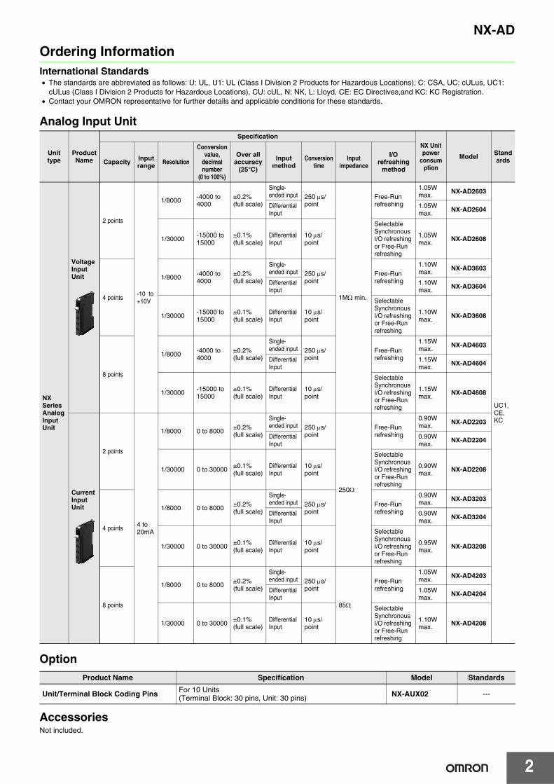
Ordering InformationInternational Standards• The standards are abbreviated as follows: U: UL, U1: UL (Class I Division 2 Products for Hazardous Locations), C: CSA, UC: cULus, UC1:
cULus (Class I Division 2 Products for Hazardous Locations), CU: cUL, N: NK, L: Lloyd, CE: EC Directives,and KC: KC Registration.• Contact your OMRON representative for further details and applicable conditions for these standards.
Analog Input Unit
Option
AccessoriesNot included.
Unit type
Product Name
SpecificationNX Unit power
consumption
Model StandardsCapacity Input
range Resolution
Conversion value,
decimal number
(0 to 100%)
Over all accuracy
(25°C)
Input method
Conversion time
Input impedance
I/O refreshing
method
NX Series Analog Input Unit
Voltage Input Unit
2 points
-10 to +10V
1/8000 -4000 to 4000
±0.2%(full scale)
Single-ended input 250 μs/
point
1MΩ min.
Free-Run refreshing
1.05W max.
NX-AD2603
UC1,CE,KC
Differential Input
1.05W max.
NX-AD2604
1/30000-15000 to 15000
±0.1%(full scale)
Differential Input
10 μs/point
Selectable Synchronous I/O refreshing or Free-Run refreshing
1.05W max. NX-AD2608
4 points
1/8000 -4000 to 4000
±0.2%(full scale)
Single-ended input 250 μs/
pointFree-Run refreshing
1.10W max. NX-AD3603
Differential Input
1.10W max. NX-AD3604
1/30000 -15000 to 15000
±0.1%(full scale)
Differential Input
10 μs/point
Selectable Synchronous I/O refreshing or Free-Run refreshing
1.10W max. NX-AD3608
8 points
1/8000 -4000 to 4000
±0.2%(full scale)
Single-ended input 250 μs/
pointFree-Run refreshing
1.15W max. NX-AD4603
Differential Input
1.15W max. NX-AD4604
1/30000 -15000 to 15000
±0.1%(full scale)
Differential Input
10 μs/point
Selectable Synchronous I/O refreshing or Free-Run refreshing
1.15W max. NX-AD4608
Current Input Unit
2 points
4 to 20mA
1/8000 0 to 8000 ±0.2%(full scale)
Single-ended input 250 μs/
point
250Ω
Free-Run refreshing
0.90W max. NX-AD2203
Differential Input
0.90W max. NX-AD2204
1/30000 0 to 30000 ±0.1%(full scale)
Differential Input
10 μs/point
Selectable Synchronous I/O refreshing or Free-Run refreshing
0.90W max. NX-AD2208
4 points
1/8000 0 to 8000±0.2%(full scale)
Single-ended input 250 μs/
pointFree-Run refreshing
0.90W max.
NX-AD3203
Differential Input
0.90W max. NX-AD3204
1/30000 0 to 30000 ±0.1%(full scale)
Differential Input
10 μs/point
Selectable Synchronous I/O refreshing or Free-Run refreshing
0.95W max. NX-AD3208
8 points
1/8000 0 to 8000 ±0.2%(full scale)
Single-ended input 250 μs/
point
85Ω
Free-Run refreshing
1.05W max. NX-AD4203
Differential Input
1.05W max. NX-AD4204
1/30000 0 to 30000 ±0.1%(full scale)
Differential Input
10 μs/point
Selectable Synchronous I/O refreshing or Free-Run refreshing
1.10W max. NX-AD4208
Product Name Specification Model Standards
Unit/Terminal Block Coding Pins For 10 Units(Terminal Block: 30 pins, Unit: 30 pins) NX-AUX02 ---

3
NX-AD
General Specification
Item Specification
Enclosure Mounted in a panel
Grounding method Ground to 100 Ω or less
Operating environment
Ambient operating temperature 0 to 55°C
Ambient operating humidity 10% to 95% (with no condensation or icing)
Atmosphere Must be free from corrosive gases.
Ambient storage temperature −25 to 70°C (with no condensation or icing)
Altitude 2,000 m max.
Pollution degree 2 or less: Conforms to JIS B3502 and IEC 61131-2.
Noise immunity 2 kV on power supply line (Conforms to IEC61000-4-4.)
Overvoltage category Category II: Conforms to JIS B3502 and IEC 61131-2.
EMC immunity level Zone B
Vibration resistance
Conforms to IEC 60068-2-6.5 to 8.4 Hz with 3.5-mm amplitude, 8.4 to 150 Hz, acceleration of 9.8 m/s2, 100 min each in X, Y, and Z directions (10 sweeps of 10 min each = 100 min total)
Shock resistance IConforms to IEC 60068-2-27. 147 m/s2, 3 times each in X, Y, and Z directions
Applicable standards cULus: Listed UL508 and ANSI/ISA 12.12.01EC: EN 61131-2 and C-Tick, KC Registration

NX-AD
4
Analog Input Unit SpecificationsAnalog Input Unit (voltage input type) 2 points NX-AD2603Unit name Analog Input Unit (voltage input type) Model NX-AD2603
Capacity 2 points External connection terminals
Screwless clamping terminal block (8 terminals)
I/O refreshing method Free-Run refreshing
Indicator
TS indicator Input method Single-ended input
Input range -10 to +10 V
Input conversion range -5 to 105% (full scale)
Absolute maximum rating ±15 V
Input impedance 1 MΩ min.
Resolution 1/8000 (full scale)
Overall accuracy
25°C ±0.2% (full scale)
0 to 55°C ±0.4% (full scale)
Conversion time 250 μs/point
Dimensions 12 (W) x 100 (H) x 71 (D) Isolation methodBetween the input and the NX bus: Power = Transformer, Signal = Digital isolator (no isolation between inputs)
Insulation resistance 20 MΩ min. between isolated circuits (at 100 VDC) Dielectric strength 510 VAC between isolated circuits for 1
minute at a leakage current of 5 mA max.
I/O power supply method Supply from the NX bus Current capacity of I/O
power supply terminalIOV: 0.1 A/terminal max.,IOG: 0.1 A/terminal max.
NX Unit power consumption 1.05 W max. I/O current consumption No consumption
Weight 70 g max.
Circuit layout
Installation orientation and restrictions
Installation orientation: Possible in 6 orientations.Restrictions: No restrictions
Terminal connection diagram
Input disconnection detection Not supported.
AG: Analog circuit internal GND
AMP
IOV
Input1+ to 2+
IOG
AG
NX bus connector (left)
Terminal block
I/O power supply +
I/O power supply −
I/O power supply +
I/O power supply −
NX bus connector (right)
1 MΩ
IOV
IOG
IOV
IOG
IOV
IOG
IOV
IOG
A1 B1
A8 B8
24 VDC
A1 B1
A8 B8
IOV
IOG
NC
IOV
IOG
NC
Input +
24 V (Sensor power supply +)
0 V (Sensor power supply − / Input −)
Three-wire sensor
Additional I/O Power Supply Unit
Input1+ Input2+
Voltage Input UnitNX-AD2603
The NC terminal is not connected to the internal circuit.

NX-AD
5
Analog Input Unit (voltage input type) 2 points NX-AD2604Unit name Analog Input Unit (voltage input type) Model NX-AD2604
Capacity 2 points External connection terminals
Screwless clamping terminal block (8 terminals)
I/O refreshing method Free-Run refreshing
Indicator
TS indicator Input method Differential Input
Input range -10 to +10 V
Input conversion range -5 to 105% (full scale)
Absolute maximum rating ±15 V
Input impedance 1 MΩ min.
Resolution 1/8000 (full scale)
Overall accuracy
25°C ±0.2% (full scale)
0 to 55°C ±0.4% (full scale)
Conversion time 250 μs/point
Dimensions 12 (W) x 100 (H) x 71 (D) Isolation methodBetween the input and the NX bus: Power = Transformer, Signal = Digital isolator (no isolation between inputs)
Insulation resistance 20 MΩ min. between isolated circuits (at 100 VDC) Dielectric strength 510 VAC between isolated circuits for 1
minute at a leakage current of 5 mA max.
I/O power supply method No supply Current capacity of I/O
power supply terminal Without I/O power supply terminals
NX Unit power consumption 1.05 W max. I/O current consumption No consumption
Weight 70 g max.
Circuit layout
Installation orientation and restrictions
Installation orientation: Possible in 6 orientations.Restrictions: No restrictions
Terminal connection diagram
Input disconnection detection Not supported.
AMP
AG
AG
510 KΩ510 KΩ
Input1+ to 2+
NX bus connector (left)
Terminal block
I/O power supply +
I/O power supply −
I/O power supply +
I/O power supply −
NX bus connector (right)
Input1− to 2−
AG: Analog circuit internal GND
A1 B1
A8 B8
AG
NC
AG
NC
AG terminal is connected to 0 V of analog circuit inside the Unit.It is not necessary to wire AG terminal normally.
Input +
Input −
Input1+
Voltage Input UnitNX-AD2604
Input1−
Input2+
Input2−

6
NX-AD
Analog Input Unit (voltage input type) 2 points NX-AD2608Unit name Analog Input Unit (voltage input type) Model NX-AD2608
Capacity 2 points External connection terminals
Screwless clamping terminal block (8 terminals)
I/O refreshing method Selectable Synchronous I/O refreshing or Free-Run refreshing
Indicator
TS indicator Input method Differential Input
Input range -10 to +10 V
Input conversion range -5 to 105% (full scale)
Absolute maximum rating ±15 V
Input impedance 1 MΩ min.
Resolution 1/30000 (full scale)
Overall accuracy
25°C ±0.1% (full scale)
0 to 55°C ±0.2% (full scale)
Conversion time 10 μs/point
Dimensions 12 (W) x 100 (H) x 71 (D) Isolation methodBetween the input and the NX bus: Power = Transformer, Signal = Digital isolator (no isolation between inputs)
Insulation resistance 20 MΩ min. between isolated circuits (at 100 VDC) Dielectric strength 510 VAC between isolated circuits for 1
minute at a leakage current of 5 mA max.
I/O power supply method No supply Current capacity of I/O
power supply terminal Without I/O power supply terminals
NX Unit power consumption 1.05 W max. I/O current consumption No consumption
Weight 70 g max.
Circuit layout
Installation orientation and restrictions
Installation orientation: Possible in 6 orientations.Restrictions: No restrictions
Terminal connection diagram
Input disconnection detection Not supported.
AMP
AG
AG510 KΩ510 KΩ
Input1+ to 2+
NX bus connector (left)
Terminal block
I/O power supply +
I/O power supply −
I/O power supply +
I/O power supply −
NX bus connector (right)
Input1− to 2−
AG: Analog circuit internal GND
A1 B1
A8 B8
AG
NC
AG
NC
AG terminal is connected to 0 V of analog circuit inside the Unit.It is not necessary to wire AG terminal normally.
Input +
Input −
Input1+
Voltage Input UnitNX-AD2608
Input1−
Input2+
Input2−
NX-AD
7
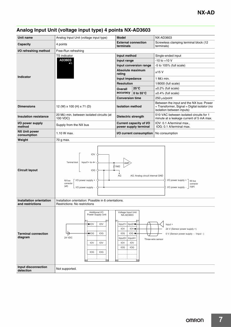
Analog Input Unit (voltage input type) 4 points NX-AD3603Unit name Analog Input Unit (voltage input type) Model NX-AD3603
Capacity 4 points External connection terminals
Screwless clamping terminal block (12 terminals)
I/O refreshing method Free-Run refreshing
Indicator
TS indicator Input method Single-ended input
Input range -10 to +10 V
Input conversion range -5 to 105% (full scale)
Absolute maximum rating ±15 V
Input impedance 1 MΩ min.
Resolution 1/8000 (full scale)
Overall accuracy
25°C ±0.2% (full scale)
0 to 55°C ±0.4% (full scale)
Conversion time 250 μs/point
Dimensions 12 (W) x 100 (H) x 71 (D) Isolation methodBetween the input and the NX bus: Power = Transformer, Signal = Digital isolator (no isolation between inputs)
Insulation resistance 20 MΩ min. between isolated circuits (at 100 VDC) Dielectric strength 510 VAC between isolated circuits for 1
minute at a leakage current of 5 mA max.
I/O power supply method Supply from the NX bus Current capacity of I/O
power supply terminalIOV: 0.1 A/terminal max., IOG: 0.1 A/terminal max.
NX Unit power consumption 1.10 W max. I/O current consumption No consumption
Weight 70 g max.
Circuit layout
Installation orientation and restrictions
Installation orientation: Possible in 6 orientations.Restrictions: No restrictions
Terminal connection diagram
Input disconnection detection Not supported.
AG
1MΩAMP
IOV
IOG
Input1+ to 4+
NX bus connector (left)
Terminal block
I/O power supply +
I/O power supply −
I/O power supply +
I/O power supply −
NX bus connector (right)
AG: Analog circuit internal GND
Input +
24 V (Sensor power supply +)
0 V (Sensor power supply − / Input −)
Three-wire sensor
IOV
IOG
IOV
IOG
IOV
IOG
IOV
IOG
IOG
IOV
IOV
A1 B1
A8 B8
IOG
IOG
IOV
IOV
IOG
24 VDC
A1 B1
A8 B8
Additional I/O Power Supply Unit
Input1+ Input2+
Voltage Input UnitNX-AD3603
Input3+ Input4+

8
NX-AD
Analog Input Unit (voltage input type) 4 points NX-AD3604Unit name Analog Input Unit (voltage input type) Model NX-AD3604
Capacity 4 points External connection terminals
Screwless clamping terminal block (12 terminals)
I/O refreshing method Free-Run refreshing
Indicator
TS indicator Input method Differential Input
Input range -10 to +10 V
Input conversion range -5 to 105% (full scale)
Absolute maximum rating ±15 V
Input impedance 1 MΩ min.
Resolution 1/8000 (full scale)
Overall accuracy
25°C ±0.2% (full scale)
0 to 55°C ±0.4% (full scale)
Conversion time 250 μs/point
Dimensions 12 (W) x 100 (H) x 71 (D) Isolation methodBetween the input and the NX bus: Power = Transformer, Signal = Digital isolator (no isolation between inputs)
Insulation resistance 20 MΩ min. between isolated circuits (at 100 VDC) Dielectric strength 510 VAC between isolated circuits for 1
minute at a leakage current of 5 mA max.
I/O power supply method No supply Current capacity of I/O
power supply terminal Without I/O power supply terminals
NX Unit power consumption 1.10 W max. I/O current consumption No consumption
Weight 70 g max.
Circuit layout
Installation orientation and restrictions
Installation orientation: Possible in 6 orientations.Restrictions: No restrictions
Terminal connection diagram
Input disconnection detection Not supported.
AMP
AG
AG
Input1+ to 4+
NX bus connector (left)
Terminal block
I/O power supply +
I/O power supply −
I/O power supply +
I/O power supply −
NX bus connector (right)
Input1− to 4−
510 KΩ510 KΩ
AG: Analog circuit internal GND
AG
A1 B1
A8 B8
AG
AG
AG
AG terminal is connected to 0 V of analog circuit inside the Unit.It is not necessary to wire AG terminal normally.
Input +
Input −
Input1+
Voltage Input UnitNX-AD3604
Input1−
Input2+
Input2−
Input3+
Input3−
Input4+
Input4−

NX-AD
9
Analog Input Unit (voltage input type) 4 points NX-AD3608Unit name Analog Input Unit (voltage input type) Model NX-AD3608
Capacity 4 points External connection terminals
Screwless clamping terminal block (12 terminals)
I/O refreshing method Selectable Synchronous I/O refreshing or Free-Run refreshing
Indicator
TS indicator Input method Differential Input
Input range -10 to +10 V
Input conversion range -5 to 105% (full scale)
Absolute maximum rating ±15 V
Input impedance 1 MΩ min.
Resolution 1/30000 (full scale)
Overall accuracy
25°C ±0.1% (full scale)
0 to 55°C ±0.2% (full scale)
Conversion time 10 μs/point
Dimensions 12 (W) x 100 (H) x 71 (D) Isolation methodBetween the input and the NX bus: Power = Transformer, Signal = Digital isolator (no isolation between inputs)
Insulation resistance 20 MΩ min. between isolated circuits (at 100 VDC) Dielectric strength 510 VAC between isolated circuits for 1
minute at a leakage current of 5 mA max.
I/O power supply method No supply Current capacity of I/O
power supply terminal Without I/O power supply terminals
NX Unit power consumption 1.10 W max. I/O current consumption No consumption
Weight 70 g max.
Circuit layout
Installation orientation and restrictions
Installation orientation: Possible in 6 orientations.Restrictions: No restrictions
Terminal connection diagram
Input disconnection detection Not supported.
AMP
AG
AG
Input1+ to 4+
NX bus connector (left)
Terminal block
I/O power supply +
I/O power supply −
I/O power supply +
I/O power supply −
NX bus connector (right)
Input1− to 4−
510 KΩ510 KΩ
AG: Analog circuit internal GND
AG
A1 B1
A8 B8
AG
AG
AG
AG terminal is connected to 0 V of analog circuit inside the Unit.It is not necessary to wire AG terminal normally.
Input +
Input −
Input1+
Voltage Input UnitNX-AD3608
Input1−
Input2+
Input2−
Input3+
Input3−
Input4+
Input4−

10
NX-AD
Analog Input Unit (voltage input type) 8 points NX-AD4603Unit name Analog Input Unit (voltage input type) Model NX-AD4603
Capacity 8 points External connection terminals
Screwless clamping terminal block (16 terminals)
I/O refreshing method Free-Run refreshing
Indicator
TS indicator Input method Single-ended input
Input range -10 to +10 V
Input conversion range -5 to 105% (full scale)
Absolute maximum rating ±15 V
Input impedance 1 MΩ min.
Resolution 1/8000 (full scale)
Overall accuracy
25°C ±0.2% (full scale)
0 to 55°C ±0.4% (full scale)
Conversion time 250 μs/point
Dimensions 12 (W) x 100 (H) x 71 (D) Isolation methodBetween the input and the NX bus: Power = Transformer, Signal = Digital isolator (no isolation between inputs)
Insulation resistance 20 MΩ min. between isolated circuits (at 100 VDC) Dielectric strength 510 VAC between isolated circuits for 1
minute at a leakage current of 5 mA max.
I/O power supply method Supply from the NX bus Current capacity of I/O
power supply terminal IOG: 0.1 A/terminal max.
NX Unit power consumption 1.15 W max. I/O current consumption No consumption
Weight 70 g max.
Circuit layout
Installation orientation and restrictions
Installation orientation: Possible in 6 orientations.Restrictions: No restrictions
Terminal connection diagram
Input disconnection detection Not supported.
AG
AMP
NX bus connector (left)
Terminal block
I/O power supply +
I/O power supply −
I/O power supply +
I/O power supply −
NX bus connector (right)
1 MΩ
AG: Analog circuit internal GND
IOG
Input1+ to 8+
Input +
24 V (Sensor power supply +)0 V (Sensor power supply − / I
Three-wire sensor
IOV
IOV
IOV
IOV
IOV
IOV
IOV
IOV
IOV
IOV
IOV
IOV
IOV
IOV
IOV
IOV
IOG
A1 B1
A8 B8
IOG
IOG
IOG
IOG
IOG IOG
IOG
IOV
IOG
IOV
IOG
IOV
IOG
IOV
IOG
24 VDC
A1 B1
A8 B8
A1 B1
A8 B8
Additional I/O Power Supply Unit
Voltage Input UnitNX-AD4603
I/O Power SupplyConnection Unit
Input1+ Input2+
Input3+ Input4+
Input7+ Input8+
Input5+ Input6+

NX-AD
11
Analog Input Unit (voltage input type) 8 points NX-AD4604Unit name Analog Input Unit (voltage input type) Model NX-AD4604
Capacity 8 points External connection terminals
Screwless clamping terminal block (16 terminals)
I/O refreshing method Free-Run refreshing
Indicator
TS indicator Input method Differential Input
Input range -10 to +10 V
Input conversion range -5 to 105% (full scale)
Absolute maximum rating ±15 V
Input impedance 1 MΩ min.
Resolution 1/8000 (full scale)
Overall accuracy
25°C ±0.2% (full scale)
0 to 55°C ±0.4% (full scale)
Conversion time 250 μs/point
Dimensions 12 (W) x 100 (H) x 71 (D) Isolation methodBetween the input and the NX bus: Power = Transformer, Signal = Digital isolator (no isolation between inputs)
Insulation resistance 20 MΩ min. between isolated circuits (at 100 VDC) Dielectric strength 510 VAC between isolated circuits for 1
minute at a leakage current of 5 mA max.
I/O power supply method No supply Current capacity of I/O
power supply terminal Without I/O power supply terminals
NX Unit power consumption 1.15 W max. I/O current consumption No consumption
Weight 70 g max.
Circuit layout
Installation orientation and restrictions
Installation orientation: Possible in 6 orientations.Restrictions: No restrictions
Terminal connection diagram
Input disconnection detection Not supported.
AMP
AGAG
Input1+ to 8+
NX bus connector (left)
Terminal block
I/O power supply +
I/O power supply −
I/O power supply +
I/O power supply −
NX bus connector (right)
Input1− to 8−
510 KΩ510 KΩ
AG: Analog circuit internal GND
A1 B1
A8 B8
Voltage Input UnitNX-AD4604
Input1+
Input1−
Input2+
Input2−
Input3+
Input3−
Input4+
Input4−
Input5+
Input5−
Input6+
Input6−
Input7+
Input7−
Input8+
Input8−
Input +
Input −

NX-AD
12
Analog Input Unit (voltage input type) 8 points NX-AD4608Unit name Analog Input Unit (voltage input type) Model NX-AD4608
Capacity 8 points External connection terminals
Screwless clamping terminal block (16 terminals)
I/O refreshing method Selectable Synchronous I/O refreshing or Free-Run refreshing
Indicator
TS indicator Input method Differential Input
Input range -10 to +10 V
Input conversion range -5 to 105% (full scale)
Absolute maximum rating ±15 V
Input impedance 1 MΩ min.
Resolution 1/30000 (full scale)
Overall accuracy
25°C ±0.1% (full scale)
0 to 55°C ±0.2% (full scale)
Conversion time 10 μs/point
Dimensions 12 (W) x 100 (H) x 71 (D) Isolation methodBetween the input and the NX bus: Power = Transformer, Signal = Digital isolator (no isolation between inputs)
Insulation resistance 20 MΩ min. between isolated circuits (at 100 VDC) Dielectric strength 510 VAC between isolated circuits for 1
minute at a leakage current of 5 mA max.
I/O power supply method No supply Current capacity of I/O
power supply terminal Without I/O power supply terminals
NX Unit power consumption 1.15 W max. I/O current consumption No consumption
Weight 70 g max.
Circuit layout
Installation orientation and restrictions
Installation orientation: Possible in 6 orientations.Restrictions: No restrictions
Terminal connection diagram
Input disconnection detection Not supported.
AMP
AG AG
Input1+ to 8+
NX bus connector (left)
Terminal block
I/O power supply +
I/O power supply −
I/O power supply +
I/O power supply −
NX bus connector (right)
Input1− to 8−
510 KΩ510 KΩ
AG: Analog circuit internal GND
A1 B1
A8 B8
Voltage Input UnitNX-AD4604
Input1+
Input1−
Input2+
Input2−
Input3+
Input3−
Input4+
Input4−
Input5+
Input5−
Input6+
Input6−
Input7+
Input7−
Input8+
Input8−
Input +
Input −
NX-AD
13
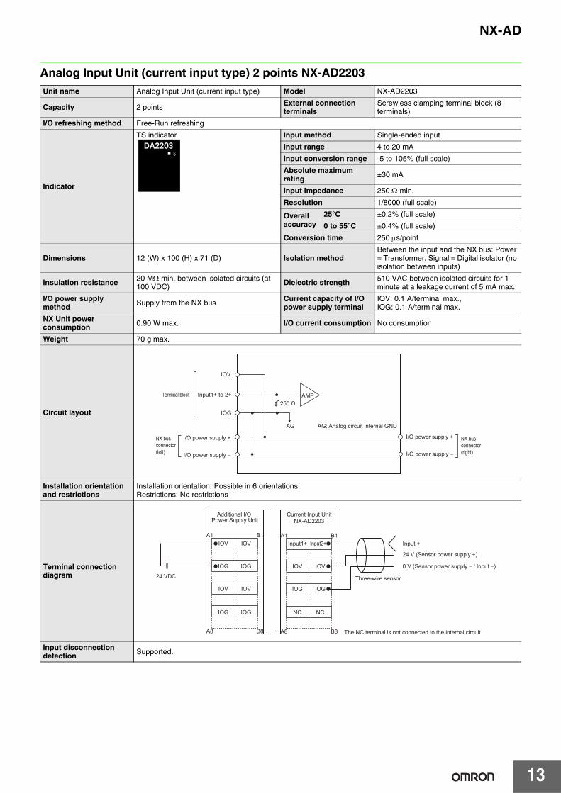
Analog Input Unit (current input type) 2 points NX-AD2203Unit name Analog Input Unit (current input type) Model NX-AD2203
Capacity 2 points External connection terminals
Screwless clamping terminal block (8 terminals)
I/O refreshing method Free-Run refreshing
Indicator
TS indicator Input method Single-ended input
Input range 4 to 20 mA
Input conversion range -5 to 105% (full scale)
Absolute maximum rating ±30 mA
Input impedance 250 Ω min.
Resolution 1/8000 (full scale)
Overall accuracy
25°C ±0.2% (full scale)
0 to 55°C ±0.4% (full scale)
Conversion time 250 μs/point
Dimensions 12 (W) x 100 (H) x 71 (D) Isolation methodBetween the input and the NX bus: Power = Transformer, Signal = Digital isolator (no isolation between inputs)
Insulation resistance 20 MΩ min. between isolated circuits (at 100 VDC) Dielectric strength 510 VAC between isolated circuits for 1
minute at a leakage current of 5 mA max.
I/O power supply method Supply from the NX bus Current capacity of I/O
power supply terminalIOV: 0.1 A/terminal max., IOG: 0.1 A/terminal max.
NX Unit power consumption 0.90 W max. I/O current consumption No consumption
Weight 70 g max.
Circuit layout
Installation orientation and restrictions
Installation orientation: Possible in 6 orientations.Restrictions: No restrictions
Terminal connection diagram
Input disconnection detection Supported.
AMP
IOV
IOG
AG
250 ΩInput1+ to 2+
NX bus connector (left)
Terminal block
I/O power supply +
I/O power supply −
I/O power supply +
I/O power supply −
NX bus connector (right)
AG: Analog circuit internal GND
IOV
IOG
IOV
IOG
IOV
IOG
IOV
IOG
A1 B1
A8 B8
24 VDC
A1 B1
A8 B8
IOV
IOG
NC
IOV
IOG
NC
Input +
24 V (Sensor power supply +)
0 V (Sensor power supply − / Input −)
Three-wire sensor
Additional I/O Power Supply Unit
Input1+ Input2+
Current Input UnitNX-AD2203
The NC terminal is not connected to the internal circuit.

NX-AD
14
Analog Input Unit (current input type) 2 points NX-AD2204Unit name Analog Input Unit (current input type) Model NX-AD2204
Capacity 2 points External connection terminals
Screwless clamping terminal block (8 terminals)
I/O refreshing method Free-Run refreshing
Indicator
TS indicator Input method Differential Input
Input range 4 to 20 mA
Input conversion range -5 to 105% (full scale)
Absolute maximum rating ±30 mA
Input impedance 250 Ω min.
Resolution 1/8000 (full scale)
Overall accuracy
25°C ±0.2% (full scale)
0 to 55°C ±0.4% (full scale)
Conversion time 250 μs/point
Dimensions 12 (W) x 100 (H) x 71 (D) Isolation methodBetween the input and the NX bus: Power = Transformer, Signal = Digital isolator (no isolation between inputs)
Insulation resistance 20 MΩ min. between isolated circuits (at 100 VDC) Dielectric strength 510 VAC between isolated circuits for 1
minute at a leakage current of 5 mA max.
I/O power supply method No supply Current capacity of I/O
power supply terminal Without I/O power supply terminals
NX Unit power consumption 0.90 W max. I/O current consumption No consumption
Weight 70 g max.
Circuit layout
Installation orientation and restrictions
Installation orientation: Possible in 6 orientations.Restrictions: No restrictions
Terminal connection diagram
Input disconnection detection Supported.
AMP
AG
AG
250 Ω
Input1+ to 2+
NX bus connector (left)
Terminal block
I/O power supply +
I/O power supply −
I/O power supply +
I/O power supply −
NX bus connector (right)
Input1− to 2−
510 KΩ510 KΩAG: Analog circuit internal GND
A1 B1
A8 B8
AG
NC
AG
NC
AG terminal is connected to 0 V of analog circuit inside the Unit.It is not necessary to wire AG terminal normally.
Input +
Input −
Input1+
Current Input UnitNX-AD2204
Input1−
Input2+
Input2−

NX-AD
15
Analog Input Unit (current input type) 2 points NX-AD2208Unit name Analog Input Unit (current input type) Model NX-AD2208
Capacity 2 points External connection terminals
Screwless clamping terminal block (8 terminals)
I/O refreshing method Selectable Synchronous I/O refreshing or Free-Run refreshing
Indicator
TS indicator Input method Differential Input
Input range 4 to 20 mA
Input conversion range -5 to 105% (full scale)
Absolute maximum rating ±30 mA
Input impedance 250 Ω
Resolution 1/30000 (full scale)
Overall accuracy
25°C ±0.1% (full scale)
0 to 55°C ±0.2% (full scale)
Conversion time 10 μs/point
Dimensions 12 (W) x 100 (H) x 71 (D) Isolation methodBetween the input and the NX bus: Power = Transformer, Signal = Digital isolator (no isolation between inputs)
Insulation resistance 20 MΩ min. between isolated circuits (at 100 VDC) Dielectric strength 510 VAC between isolated circuits for 1
minute at a leakage current of 5 mA max.
I/O power supply method No supply Current capacity of I/O
power supply terminal Without I/O power supply terminals
NX Unit power consumption 0.90 W max. I/O current consumption No consumption
Weight 70 g max.
Circuit layout
Installation orientation and restrictions
Installation orientation: Possible in 6 orientations.Restrictions: No restrictions
Terminal connection diagram
Input disconnection detection Supported.
AMP
AG
AG
250 Ω
Input1+ to 2+
NX bus connector (left)
Terminal block
I/O power supply +
I/O power supply −
I/O power supply +
I/O power supply −
NX bus connector (right)
Input1− to 2−
510 KΩ510 KΩAG: Analog circuit internal GND
A1 B1
A8 B8
AG
NC
AG
NC
AG terminal is connected to 0 V of analog circuit inside the Unit.It is not necessary to wire AG terminal normally.
Input +
Input −
Input1+
Current Input UnitNX-AD2208
Input1−
Input2+
Input2−
NX-AD
16
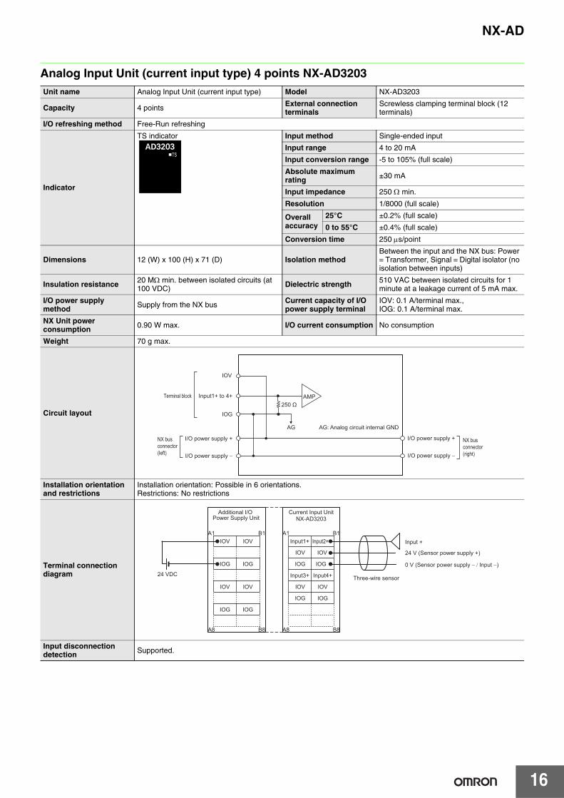
Analog Input Unit (current input type) 4 points NX-AD3203Unit name Analog Input Unit (current input type) Model NX-AD3203
Capacity 4 points External connection terminals
Screwless clamping terminal block (12 terminals)
I/O refreshing method Free-Run refreshing
Indicator
TS indicator Input method Single-ended input
Input range 4 to 20 mA
Input conversion range -5 to 105% (full scale)
Absolute maximum rating ±30 mA
Input impedance 250 Ω min.
Resolution 1/8000 (full scale)
Overall accuracy
25°C ±0.2% (full scale)
0 to 55°C ±0.4% (full scale)
Conversion time 250 μs/point
Dimensions 12 (W) x 100 (H) x 71 (D) Isolation methodBetween the input and the NX bus: Power = Transformer, Signal = Digital isolator (no isolation between inputs)
Insulation resistance 20 MΩ min. between isolated circuits (at 100 VDC) Dielectric strength 510 VAC between isolated circuits for 1
minute at a leakage current of 5 mA max.
I/O power supply method Supply from the NX bus Current capacity of I/O
power supply terminalIOV: 0.1 A/terminal max., IOG: 0.1 A/terminal max.
NX Unit power consumption 0.90 W max. I/O current consumption No consumption
Weight 70 g max.
Circuit layout
Installation orientation and restrictions
Installation orientation: Possible in 6 orientations.Restrictions: No restrictions
Terminal connection diagram
Input disconnection detection Supported.
AG
AMP
IOV
IOG
Input1+ to 4+
NX bus connector (left)
Terminal block
I/O power supply +
I/O power supply −
I/O power supply +
I/O power supply −
NX bus connector (right)
250 Ω
AG: Analog circuit internal GND
Input +
24 V (Sensor power supply +)
0 V (Sensor power supply − / Input −)
Three-wire sensor
IOV
IOG
IOV
IOG
IOV
IOG
IOV
IOG
IOG
IOV
IOV
A1 B1
A8 B8
IOG
IOG
IOV
IOV
IOG
24 VDC
A1 B1
A8 B8
Additional I/O Power Supply Unit
Current Input UnitNX-AD3203
Input1+ Input2+
Input3+ Input4+

NX-AD
17
Analog Input Unit (current input type) 4 points NX-AD3204Unit name Analog Input Unit (current input type) Model NX-AD3204
Capacity 4 points External connection terminals
Screwless clamping terminal block (12 terminals)
I/O refreshing method Free-Run refreshing
Indicator
TS indicator Input method Differential Input
Input range 4 to 20 mA
Input conversion range -5 to 105% (full scale)
Absolute maximum rating ±30 mA
Input impedance 250 Ω min.
Resolution 1/8000 (full scale)
Overall accuracy
25°C ±0.2% (full scale)
0 to 55°C ±0.4% (full scale)
Conversion time 250 μs/point
Dimensions 12 (W) x 100 (H) x 71 (D) Isolation methodBetween the input and the NX bus: Power = Transformer, Signal = Digital isolator (no isolation between inputs)
Insulation resistance 20 MΩ min. between isolated circuits (at 100 VDC) Dielectric strength 510 VAC between isolated circuits for 1
minute at a leakage current of 5 mA max.
I/O power supply method No supply Current capacity of I/O
power supply terminal Without I/O power supply terminals
NX Unit power consumption 0.90 W max. I/O current consumption No consumption
Weight 70 g max.
Circuit layout
Installation orientation and restrictions
Installation orientation: Possible in 6 orientations.Restrictions: No restrictions
Terminal connection diagram
Input disconnection detection Supported.
AMP
AG
AG
Input1+ to 4+
NX bus connector (left)
Terminal block
I/O power supply +
I/O power supply −
I/O power supply +
I/O power supply −
NX bus connector (right)
Input1− to 4−
510 KΩ510 KΩ
250 Ω
AG: Analog circuit internal GND
AG
A1 B1
A8 B8
AG
AG
AG
AG terminal is connected to 0 V of analog circuit inside the Unit.It is not necessary to wire AG terminal normally.
Input +
Input −
Input1+
Current Input UnitNX-AD3204
Input1−
Input2+
Input2−
Input3+
Input3−
Input4+
Input4−
NX-AD
18
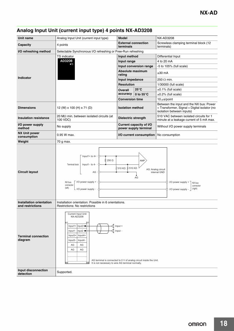
Analog Input Unit (current input type) 4 points NX-AD3208Unit name Analog Input Unit (current input type) Model NX-AD3208
Capacity 4 points External connection terminals
Screwless clamping terminal block (12 terminals)
I/O refreshing method Selectable Synchronous I/O refreshing or Free-Run refreshing
Indicator
TS indicator Input method Differential Input
Input range 4 to 20 mA
Input conversion range -5 to 105% (full scale)
Absolute maximum rating ±30 mA
Input impedance 250 Ω min.
Resolution 1/30000 (full scale)
Overall accuracy
25°C ±0.1% (full scale)
0 to 55°C ±0.2% (full scale)
Conversion time 10 μs/point
Dimensions 12 (W) x 100 (H) x 71 (D) Isolation methodBetween the input and the NX bus: Power = Transformer, Signal = Digital isolator (no isolation between inputs)
Insulation resistance 20 MΩ min. between isolated circuits (at 100 VDC) Dielectric strength 510 VAC between isolated circuits for 1
minute at a leakage current of 5 mA max.
I/O power supply method No supply Current capacity of I/O
power supply terminal Without I/O power supply terminals
NX Unit power consumption 0.95 W max. I/O current consumption No consumption
Weight 70 g max.
Circuit layout
Installation orientation and restrictions
Installation orientation: Possible in 6 orientations.Restrictions: No restrictions
Terminal connection diagram
Input disconnection detection Supported.
AMP
AG
AG
Input1+ to 4+
NX bus connector (left)
Terminal block
I/O power supply +
I/O power supply −
I/O power supply +
I/O power supply −
NX bus connector (right)
Input1− to 4−
510 KΩ 510 KΩ
250 Ω
AG: Analog circuit internal GND
AG
A1 B1
A8 B8
AG
AG
AG
AG terminal is connected to 0 V of analog circuit inside the Unit.It is not necessary to wire AG terminal normally.
Input +
Input −
Input1+
Current Input UnitNX-AD3208
Input1−
Input2+
Input2−
Input3+
Input3−
Input4+
Input4−

NX-AD
19
Analog Input Unit (current input type) 8 points NX-AD4203Unit name Analog Input Unit (current input type) Model NX-AD4203
Capacity 8 points External connection terminals
Screwless clamping terminal block (16 terminals)
I/O refreshing method Free-Run refreshing
Indicator
TS indicator Input method Single-ended input
Input range 4 to 20 mA
Input conversion range -5 to 105% (full scale)
Absolute maximum rating ±30 mA
Input impedance 85 Ω
Resolution 1/8000 (full scale)
Overall accuracy
25°C ±0.2% (full scale)
0 to 55°C ±0.4% (full scale)
Conversion time 250 μs/point
Dimensions 12 (W) x 100 (H) x 71 (D) Isolation methodBetween the input and the NX bus: Power = Transformer, Signal = Digital isolator (no isolation between inputs)
Insulation resistance 20 MΩ min. between isolated circuits (at 100 VDC) Dielectric strength 510 VAC between isolated circuits for 1
minute at a leakage current of 5 mA max.
I/O power supply method Supply from the NX bus Current capacity of I/O
power supply terminal IOV: 0.1 A/terminal max.
NX Unit power consumption 1.05 W max. I/O current consumption No consumption
Weight 70 g max.
Circuit layout
Installation orientation and restrictions
Installation orientation: Possible in 6 orientations.Restrictions: No restrictions
Terminal connection diagram
Input disconnection detection Supported.
IOV
AMP
AG AG
Input1+ to 8+
NX bus connector (left)
Terminal block
I/O power supply +
I/O power supply −
I/O power supply +
I/O power supply −
NX bus connector (right)
85 ΩAG: Analog circuit internal GND
Input +
24 V (Sensor power supply +)0 V (Sensor power supply − / Input −)
Three-wire Sensor
IOG
IOG
IOG
IOG
IOG
IOG
IOG
IOG
IOG
IOG
IOG
IOG
IOG
IOG
IOG
IOG
IOV
A1 B1
A8 B8
IOV
IOV
IOV
IOV
IOV IOV
IOV
IOV
IOG
IOV
IOG
IOV
IOG
IOV
IOG
24 VDC
A1 B1
A8 B8
A1 B1
A8 B8
Additional I/O Power Supply Unit
Voltage Input UnitNX-AD4203
I/O Power SupplyConnection Unit
Input1+ Input2+
Input3+ Input4+
Input7+ Input8+
Input5+ Input6+

NX-AD
20
Analog Input Unit (current input type) 8 points NX-AD4204Unit name Analog Input Unit (current input type) Model NX-AD4204
Capacity 8 points External connection terminals
Screwless clamping terminal block (16 terminals)
I/O refreshing method Free-Run refreshing
Indicator
TS indicator Input method Differential Input
Input range 4 to 20 mA
Input conversion range -5 to 105% (full scale)
Absolute maximum rating ±30 mA
Input impedance 85 Ω
Resolution 1/8000 (full scale)
Overall accuracy
25°C ±0.2% (full scale)
0 to 55°C ±0.4% (full scale)
Conversion time 250 μs/point
Dimensions 12 (W) x 100 (H) x 71 (D) Isolation methodBetween the input and the NX bus: Power = Transformer, Signal = Digital isolator (no isolation between inputs)
Insulation resistance 20 MΩ min. between isolated circuits (at 100 VDC) Dielectric strength 510 VAC between isolated circuits for 1
minute at a leakage current of 5 mA max.
I/O power supply method No supply Current capacity of I/O
power supply terminal Without I/O power supply terminals
NX Unit power consumption 1.05 W max. I/O current consumption No consumption
Weight 70 g max.
Circuit layout
Installation orientation and restrictions
Installation orientation: Possible in 6 orientations.Restrictions: No restrictions
Terminal connection diagram
Input disconnection detection Supported.
AMP
AG AG
Input1+ to 8+
NX bus connector (left)
Terminal block
I/O power supply +
I/O power supply −
I/O power supply +
I/O power supply −
NX bus connector (right)
Input1− to 8−
510 KΩ510 KΩ
85 Ω
AG: Analog circuit internal GND
Input +
Input −
A1 B1
A8 B8
Current Input UnitNX-AD4204
Input1+
Input1−
Input2+
Input2−
Input3+
Input3−
Input4+
Input4−
Input5+
Input5−
Input6+
Input6−
Input7+
Input7−
Input8+
Input8−

21
NX-AD
Analog Input Unit (current input type) 8 points NX-AD4208
Version InformationNX Series Analog Input Unit and Sysmac Studio
Unit name Analog Input Unit (current input type) Model NX-AD4208
Capacity 8 points External connection terminals
Screwless clamping terminal block (16 terminals)
I/O refreshing method Selectable Synchronous I/O refreshing or Free-Run refreshing
Indicator
TS indicator Input method Differential Input
Input range 4 to 20 mA
Input conversion range -5 to 105% (full scale)
Absolute maximum rating ±30 mA
Input impedance 85 Ω
Resolution 1/30000 (full scale)
Overall accuracy
25°C ±0.1% (full scale)
0 to 55°C ±0.2% (full scale)
Conversion time 10 μs/point
Dimensions 12 (W) x 100 (H) x 71 (D) Isolation methodBetween the input and the NX bus: Power = Transformer, Signal = Digital isolator (no isolation between inputs)
Insulation resistance 20 MΩ min. between isolated circuits (at 100 VDC) Dielectric strength 510 VAC between isolated circuits for 1
minute at a leakage current of 5 mA max.
I/O power supply method No supply Current capacity of I/O
power supply terminal Without I/O power supply terminals
NX Unit power consumption 1.10 W max. I/O current consumption No consumption
Weight 70 g max.
Circuit layout
Installation orientation and restrictions
Installation orientation: Possible in 6 orientations.Restrictions: No restrictions
Terminal connection diagram
Input disconnection detection Supported.
NX Series Analog Output UnitSysmac Studio
Version 1.05 or lower Version 1.06 or higher
NX-AD@@@@ Not supported Supported
AMP
AG AG
Input1+ to 8+
NX bus connector (left)
Terminal block
I/O power supply +
I/O power supply −
I/O power supply +
I/O power supply −
NX bus connector (right)
Input1− to 8−
510 KΩ510 KΩ
85 Ω
AG: Analog circuit internal GND
Input +
Input −
A1 B1
A8 B8
Current Input UnitNX-AD4208
Input1+
Input1−
Input2+
Input2−
Input3+
Input3−
Input4+
Input4−
Input5+
Input5−
Input6+
Input6−
Input7+
Input7−
Input8+
Input8−

NX-AD
22
External InterfaceAnalog Input UnitNX-AD@@@@12mm Width
Terminal Blocks
Symbol Name Function
(A) NX bus connector This connector is used to connect each Unit.
(B) Indicators The indicators show the current operating status of the Unit.
(C) Terminal block The terminal block is used to connect external devices.The number of terminals depends on the type of Unit.
Symbol Name Function
(A) Terminal number indications
Terminal numbers for which A to D indicate the column, and 1 to 8 indicate the line are displayed.The terminal number is a combination of column and line, so A1 to A8 and B1 to B8 are displayed.The terminal number indications are the same regardless of the number of terminals on the terminal block.
(B) Release holes Insert a flat-blade screwdriver into these holes to connect and remove the wires.
(C) Terminal holes The wires are inserted into these holes.
(A)
(C)
(B)
12 mm width8-terminal type
(B)
12 mm width12-terminal type
12 mm width16-terminal type
(C)
(A)
A1
A2
A3
A4
A5
A6
A7
A8
B1
B2
B3
B4
B5
B6
B7
B8
A1
A2
A3
A4
A5
A6
A7
A8
B1
B2
B3
B4
B5
B6
B7
B8
A1
A2
A3
A4
A5
A6
A7
A8
B1
B2
B3
B4
B5
B6
B7
B8

23
NX-AD
Applicable WiresUsing FerrulesIf you use ferrules, attach the twisted wires to them.Observe the application instructions for your ferrules for the wire stripping length when attaching ferrules.Always use one-pin ferrules. Do not use two-pin ferrules.
The applicable ferrules, wires, and crimping tool are given in the following table.
* Some AWG 14 wires exceed 2.0 mm2 and cannot be used in the screwless clamping terminal block.
When you use any ferrules other than those in the above table, crimp them to the twisted wires so that the following processed dimensions are achieved.
Using Twisted Wires/Solid WiresIf you use the twisted wires or the solid wires, the applicable wire range and conductor length (stripping length) are as follows.Use the twisted wires to connect the ground wire to a ground of 100 Ω or less. Do not use the solid wires.
Terminal types Manufacturer Ferrule modelnumber
Applicable wire(mm2 (AWG)) Crimping tool
Terminals other than ground terminals
Phoenix Contact AI0,34-8 0.34 (#22) Phoenix Contact (The figure in parentheses is the applicable wire size.)CRIMPFOX 6 (0.25 to 6 mm2, AWG24 to 10)AI0,5-8 0.5 (#20)
AI0,5-10
AI0,75-8 0.75 (#18)
AI0,75-10
AI1,0-8 1.0 (#18)
AI1,0-10
AI1,5-8 1.5 (#16)
AI1,5-10
Ground terminals AI2,5-10 2.0 *
Terminals other than ground terminals
Weidmuller H0.14/12 0.14 (#26) Weidmuller (The figure in parentheses is the applicable wire size.)PZ6 Roto (0.14 to 6 mm2, AWG 26 to 10)H0.25/12 0.25 (#24)
H0.34/12 0.34 (#22)
H0.5/14 0.5 (#20)
H0.5/16
H0.75/14 0.75 (#18)
H0.75/16
H1.0/14 1.0 (#18)
H1.0/16
H1.5/14 1.5 (#16)
H1.5/16
Terminal types Applicable wires Conductor length (stripping length)
Ground terminals 2.0 mm2 9 to 10 mm
Terminals other than ground terminals
0.08 to 1.5 mm2
AWG28 to 16 8 to 10 mm
Finished Dimensions of Ferrules
1.6 mm max. (except ground terminals)2.0 mm max. (ground terminals)
2.4 mm max. (except ground terminals)2.7 mm max. (ground terminals)
8 to 10 mm
Conductor length (stripping length)

NX-AD
24
Dimensions (Unit/mm)
Analog Input UnitNX-AD@@@@12 mm Width
Related Manuals
Cat. No. Model number Manual name Application Description
W522NX-AD@@@@NX-DA@@@@NX-TS@@@@
NX-series Analog I/O Units User’s Manual
Learning how to use NX-series Analog I/O Units and Temperature Input Units
The hardware, setup methods, and functions of the NX-series Analog I/O Units and Temperature Input Units are described.
14.1
12.0
100
1.5
1.5
104.5
65.2
80.1
71