nxairs withdrawable medium-voltage circuit-breaker...
TRANSCRIPT

www.siemens.com.cn
NXAirSWithdrawable Medium-Voltage Circuit-BreakerSwitchgear up to 12kV, Air-Insulated
Answers for infrastructure and cities.
shpm1988.indd 1 2013/1/31 11:02:07
2
Application
3 Types
4 Typical uses
4 Classifi cation
Requirements
5 Customer benefi ts and features
Technical Data
6 Electrical data and diemensions
8 Installation Instructions
Primary Solution
14 VCB incoming/out going panel A
16Disconnect truck incoming/out going panel B
18 VCB sectionalizer C
19 Disconnect turck contact panel D
20 PT panel E
21 Metering Panel F
22Metering Panel F/Station transformer panel G
23Cable-connertor panel H/Metering panel I
Design
24 Basic panel design
25 Compartments and components
26 Introduction of compartments
Components
29 Switch devices
Standards
37 Standards, specifi cations, guidelines
Contents Application
NXAirS Withdrawable Medium-Voltage Circuit-Breaker Switchgear up to 12kV, Air-Insulated
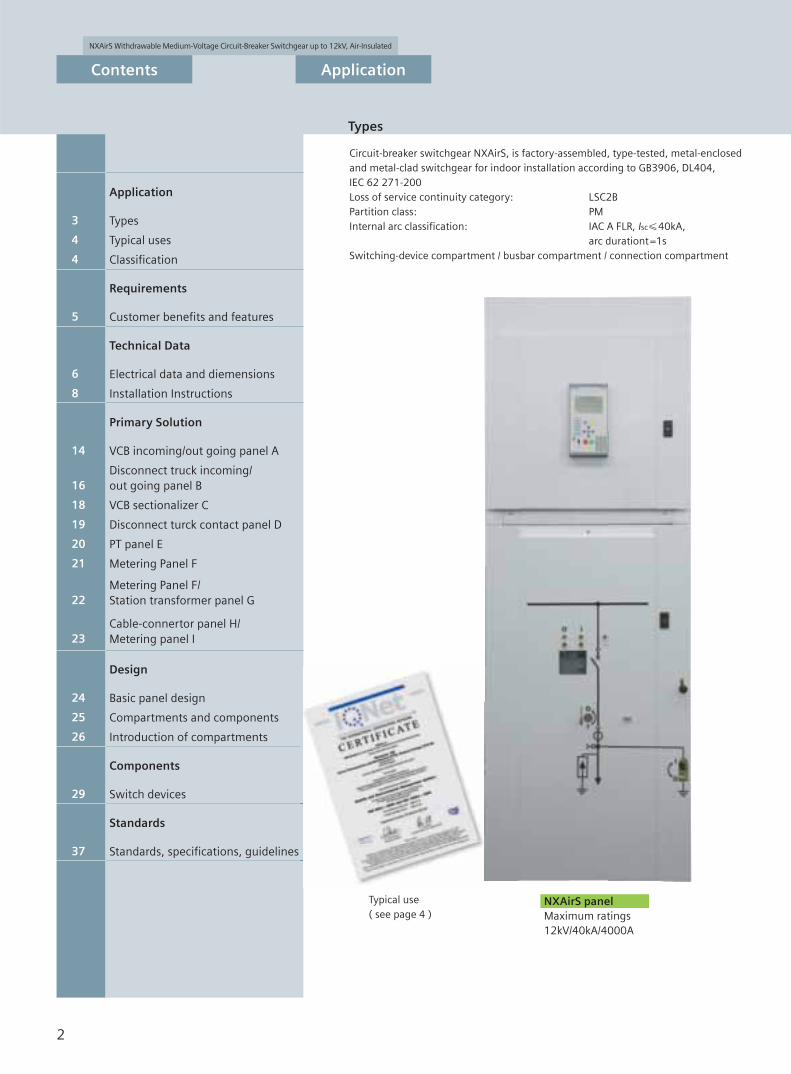
Types
shpm1988.indd 2 2013/1/29 14:13:10

NXAirS Withdrawable Medium-Voltage Circuit-Breaker Switchgear up to 12kV, Air-Insulated
3
Application
ApplicationIndustry
ApplicationMarine
NXAirS switchgear
ApplicationPublic power supply system
Typical uses
shpm1988.indd 3 2012/11/30 16:13:56

NXAirS Withdrawable Medium-Voltage Circuit-Breaker Switchgear up to 12kV, Air-Insulated
4
Application
NXAirS circuit-breaker switchgear is used in transformer substation and switching substation, mainly at the primary distribution level, e.g.
ApplicationPublic power supply system
ApplicationIndustry
Transformer substationPower plant
Cement industryAutomobile industryIron and steel worksMining industryTextile, paper and food industriesChemical industryPetroleum industryPipeline installationsOffshore installationsElectrochemical plantsPetrochemical plants
NXAirS switchgear corresponds to the following classifications according to GB3906, DL404, IEC62271-200
L SC 2B
PM
Tool-basedInterlock-basedInterlock-based and use special tools
The following internalarcclassificationsare fulfilled:
IAC A FLR, Isc, tIAC = Internalarc classification
A = 300 mm distance of indicatorsfor test (installation in closedelectricalservice location)
F = Front arrangementof indicatorsfor test
L = Lateral arrangementof indicatorsfor test
R = Rear arrangementof indicatorsfor test
Isc = Test current for
t = Arcingtime 1 s
Loss of service continuity category and partition class
Internal arc classification
Loss of service continuity category Partition classAccessibility to compartments
Busbar compartment Switching-device compartment Connection compartment
NXAirS up to 40kA
In this way,NXAirS, is suitable for unrestricted application (wall or free-standing arrangement) in electrical service locations up to the maximum short-circuit current ratings.
ApplicationMarine
Various shipsVarious offshore platforms
Typical uses Classifi cation
shpm1988.indd 4 2012/12/3 15:36:09

NXAirS Withdrawable Medium-Voltage Circuit-Breaker Switchgear up to 12kV, Air-Insulated
5
Requirements
FeaturesCustomer benefits
Peace of mindFor power supply companiesand industrial plants, thecertification of NXAirSaccording to the lateststandards has very concreteadvantages: smooth operation,exemplary availability andmaximum safety.
Saves LivesAll switchgear types of theNXAirS family are approvedwith internal arc classificationIAC A FLR, loss of servicecontinuity category LSC 2B,partition class PM. This makesthem suitable for universalinstallation, meeting thehighest requirements regardingpersonal safety.
Increases productivityFeatures such as modulardesign, type tests of the circuitbreaker in the switchgear,maximum personal safety contribute to uninterrupted operation and a remarkable increase of productivity.
Saves moneyThanks to the use of the newcircuit-breaker series SION, thecompact design of NXAirSfamily pays twice for the owner.On the one hand building costscan be reduced, and on theother hand, the maintenance-free circuit-breakers and themodular design enablecontinuous operation withoutexpensive shutdown times.
• Factory-assembled, type-tested switchgear according to GB, DL and IEC Standard• Modular design with pressure-resistant partitions (switching-device, connection, busbar
compartments and low-voltage compartment replaceable)• More than 300,000 air-insulated switchgear panels from Siemens in operation worldwide• Use of maintenance-free vacuum circuit-breakers ( 10000 operation cycles )• Type testing of the vacuum circuit-breaker • Pressure-resistant partitions• Use of standard, worldwide available components• Quality management according to ISO 9001
• All switching operations with high-voltage door closed• Metallic enclosure, earthed shutters and partitions• High-voltage compartment with reliable interlocking system.• Switchgear with internal arc classification according to IAC A FLR• Loss of service continuity category LSC 2B
• Partition class PM (metal-clad in pressure-resistant design)• isdation of separate partitions for busbar, connection and switching-device compartments
• Clear switch position indicators and control elements on the high-voltage door• Use of vacuum circuit-breakers• Standard degree of protection IP4X• Positively driven shutters• Logical mechanical interlocking system
• Modular panel design enables fast replacement of the respective compartments• Loss of service continuity category LSC 2B (separate partitions for busbar, connection and
switching-device compartments)• Resistance to internal arc fault• Use of maintenance-free vacuum circuit-breakers• Control cables in metallic wiring ducts
• Use of maintenance-free vacuum circuit-breakers ( 10000 operation cycles )• Maintenance intervals of the switchgear > 10 years• Interruption of operation reduced to a minimum by modular design, logical mechanical
interlocking system• Minimized space requirements (reduced building investments) due to compact design
Customer benefi ts and features
shpm1988.indd 5 2012/11/30 16:13:59

NXAirS Withdrawable Medium-Voltage Circuit-Breaker Switchgear up to 12kV, Air-Insulated
Technical data
6
Electrical data and dimensions
Rated values
Rated
- voltage kV 7.2 12
- frequency Hz 50 50
- short-duration power-frequency withstand voltage (phase-to-phase, phase-to-earth)
kV 32 42
- lightning impulse withstand volt.(phase-to-phase, phase-to-earth)
kV 60 75
- short-circuit breaking current max.kA 40 40* 40*
- short-time withstand current, 4s max.kA 40 40* 40*
- peak withstand current max.kA 100 100* 100*
- short-circuit making current max.kA 100 100* 100*
- normal current of busbar max.A 4000 4000 4000
- normal current of feeders: A
with circuit-breaker 4000 4000
with contactor 250 160
with disconnector link 4000 4000
with switchdisconnector 4000 4000
busbar sectionalizer 4000 4000
*: suitable to switchgear panels except for contactor Panel
Dimensions
Width W Circuit-breaker panel
mm 630A 650
1250A~2500A 800
3150A~4000A 1000
Disconnector link panel
2500A 800
3150A~4000A 1000
Substation transformer Panel 1000
Busbar sectionalizer
2500A 2 800
3150A 2 1000
Metering panel 800, 1000
Busbar connection panel 800, 1000
contactor Panel 650
Height H2)
mm
31.5kA 2200
40kA 2300
Substation transformer Panel 2500
contactor Panel 2200
Depth D3) 31.5kA and busbar current 2500A 1350
With Classic breaker
mm 31.5kA and busbar current 3150A 1450
40kA Standard Panel 1450
With EP breaker
31.5kA and busbar current 2500A 1350
31.5kA and busbar current 3150A 1500
40kA 1500
contactor Panel 1350, 1500
Weight kg1250A/31.5kA(with withdrawable cassette)
≈ 850kg
Stand ard Panel 3150A/40kA ≈ 1300kg
Notes: 1. The rated current is up to 4000A in forced ventilation condition
2. H1: The standard height from the top of the LV compartment to the ground is 2075mm.
H2: The additional height from the LV compartment to the ground is 2350mm.
3. The current of busbar is less than or equal to 2500A, and an additinal 130mm is needed to the panel depth when the busbar is accessed from the top.
The current of busbar is bigger than 2500A, and an addition 200mm is needed to the panel depth when the busbar is accessed from the top.
The standard depth of the back-compartments is 460mm for rated current less than and equal to 2000A
The Standard depth of the back-compartment is 620mm for rated current bigger than 2000A
D
Contactor Panel
-Rated short-time withstand current
main circuit 1S kA 8 8
main busbar 4S kA 40 40
-rated peak withstand current
main circuit 1S kA 20 20
main busbar 4S kA 40 40
shpm1988.indd 6 2012/12/3 15:59:24

NXAirS Withdrawable Medium-Voltage Circuit-Breaker Switchgear up to 12kV, Air-Insulated
Technical data
7
Electrical data and dimensions
note: *the switchgear is single-row arranged. If the switchgear is two-row face-to-face arranged, the dis tance between two rows should be not less than 2500mm **the dimension of touring aisle depends on the actual size of the distribution room
unit: mm
switchgear
electrical cable trench
controlling cable trench
electrical cable trench
switchgear
controlling cable trench
note: *the switchgear is sigle-row arranged. If the switchgear is two-row face-to-face arranged, the dis tance between two rows should be not less than 2500mm
unit: mm
typical cutaway view( A-A cutaway view)
electrical cable trench 800x1000
note: *the labeled sizes depend on the actual opening penal mats of suitchgear. **the labeled sizes should adjusted when installing bus structu
the top of basic structure is 1~3mm above the surface
contrding cable trencl cover is made of checkered steel plane of 5mm
contrding cable trench 250x250
unit: mm
note: *the labeled sizes depend on the actual opening penal mats of switchgear. **the labeled sizes should be adjusted when installing bus duct
the top of basic structure is 1~3mm above the surface
contrding cable trencl cover is made of checkered steel plane of 5mm
contrding cable trench 250x250
electrical cable trench 1054x1000
typical cutaway view( B-B cutaway view)
unit: mm
Basic structure, layout of panels of 650mm, 800mm, 1000mm width.
anchor bolts
anchor bolts MIB
Basic structure diagram
Cable layout
Cable layout
Switchgear against wall assemblying layout
switchgear off wall assemblying layout
Single-row arrangement (plan view)
single-busbar switchgear
For dimensions W (width) and D (depth) see table on last
page
For panel replacement: aisle for operation 1500mm, the
height from Panel top to the ceiling 800mm
For back-to-back and face-to-face arrangement, the
corresponding room dimensions apply as for single-row
arrangement.
For back-to-back arrangement, a 1200 mm wide control aisle
is required on the left or on the right of the switchgear.
The power distribution room dimensions should also refer
to comesponding building size.
shpm1988.indd 7 2013/1/31 11:06:09

NXAirS Withdrawable Medium-Voltage Circuit-Breaker Switchgear up to 12kV, Air-Insulated
Technical data
8
NXAirS 25/31.5kA
NXAirS 25/31.5kACircuit breaker Panel
Circuit breaker Panel
Substation transformer Panel
Busbar connecting / metering Panel Busbar connecting / metering Panel
Circuit breaker Panel Circuit breaker Panel
NXAirS 25/31.5kA
NXAirS transformer panel
NXAirS 25/31.5kA NXAirS 25/31.5kA
NXAirS 25/31.5kA NXAirS 25/31.5kA
Foundation layout
Connection from the rear Connection from the rear with 130mm-depth backpack
Connection from the rear with 460mm-depth backpack
Connection form the rear with620mm-depth backpack
Branch busbar/metering/PT panel Branch busbar with 130mm-depth backpack
The foundation groove for HV cable connectionThe foundation groove for control cableFixing point (60X20mm)Paralled installation channels.The channels must be flat and straight before secondary casting,and the horizontal toleramce is smaller than 0.2% (allocated to design drawings)
The drawing of special solution should refer to the additional documentsVentilation channel ( 3150A)
Foundation layout
Circuit Breaker Panel Busbar Connecting / Metering Panel
Busbar Connecting / Metering Panel
Substation Transformer Panel
The foundation groove for HV cable connection
The foundation groove for control cable
Fixing point (60X20mm)
Paralled installation channels.
The channels must be fl at and straight before
secondary casting, and the horizontal toleramce is
smaller than 0.2% (allocated to design drawings)
HV door
The drawing of special solution should refer to
the additional ducuments
Circuit Breaker Panel
Circuit Breaker Panel Busbar Connectiong/Substation Transformer Panel
Circuit Breaker Panel
Ik 31.5kA, busbar Ir 2500A, feeder Ir 2500A, suitable to classic or EP circuit breaker
Ik 31.5kA, busbar Ir 3150A, feeder Ir 2500A, suitable to classic circuit breaker
Ik 40kA,Ir 3150A, suitable to classic circuit breakerIk=40kA,In 2500A, suitable to classic circuit breaker
Installation Instructions
shpm1988.indd 8 2013/1/21 13:12:09

NXAirS Withdrawable Medium-Voltage Circuit-Breaker Switchgear up to 12kV, Air-Insulated
Technical data
9
Installation Instructions
Circuit breaker Panel
Ik=40kA, Ir 2500A,
EP circuit breaker
PT or disconnector Panel
Ik=40kA, Ir 2500A,
Ik=40kA, Ir 2500A,
EP circuit breaker, with additional rearbox
Transformer Substation PanelIk=40kA
Busbar Sectimalige PanelIk=40kA, Ir=3150A
Circuit breaker PanelIk=40kA, Ir 3150A, with EP Circuit breaker
Circuit breaker panelIk 31.5kA, Ir 630A, EP circuit breaker
Contactor PanelIk 31.5kA, busbar Ir 3150A, Ik=40kA
Contactor PanelIk 31.5kA, busbar Ir 2500A
4
1
4
2
12.5
17
1
22
0
10
68
29
0
68
11
95
50
13
15
13
50
325
650
125125
3
3
12.5
17
1
22
02
90
50
325
650
125125
12
18
14
65
15
00
1
43
2
34
13
45
68
shpm1988.indd 9 2013/1/21 13:28:10

NXAirS Withdrawable Medium-Voltage Circuit-Breaker Switchgear up to 12kV, Air-Insulated
Technical data
10
busbar current 3150A Panel with Coutactor-fuse combination equipment
40kA and 31.5kA, 3150A, Panel with Contactor-fuse combination equipment
Installation Instructions
shpm1988.indd 10 2013/1/21 13:28:28

NXAirS Withdrawable Medium-Voltage Circuit-Breaker Switchgear up to 12kV, Air-Insulated
Technical data
11
25kA/31.5kA, 630A, Panel with EP circuit breaker
40kA, 1250A, Panel with EP circuit breaker
Installation Instructions
shpm1988.indd 11 2012/11/30 16:14:12

NXAirS Withdrawable Medium-Voltage Circuit-Breaker Switchgear up to 12kV, Air-Insulated
Technical data
12
31.5kA, 3150A and 40kA, 3150A~4000APanel with EP circuit breaker
40kA, 2500A, Panel with EP circuit breaker
Installation Instructions
shpm1988.indd 12 2012/11/30 16:14:29

NXAirS Withdrawable Medium-Voltage Circuit-Breaker Switchgear up to 12kV, Air-Insulated
Technical data
13
40kA,3150A/4000A, Panel with Classic breaker*
25kA/31.5kA,1250A ~2500A Panel with Classic breaker or with EP breaker
23
00
* Additional rear box may be needed
*note: please refer to detailed information for those unlisted in the installation instruction.
Installation Instructions
shpm1988.indd 13 2012/12/3 16:11:18

NXAirS Withdrawable Medium-Voltage Circuit-Breaker Switchgear up to 12kV, Air-Insulated
Primary Solution
14
VCB incoming/outgoing panel A
shpm1988.indd 14 2012/11/30 16:17:14

NXAirS Withdrawable Medium-Voltage Circuit-Breaker Switchgear up to 12kV, Air-Insulated
Primary Solution
15
Only for rated current 1250A
Only for rated current 1250A
VCB incoming/outgoing panel A
shpm1988.indd 15 2012/11/30 16:17:14

NXAirS Withdrawable Medium-Voltage Circuit-Breaker Switchgear up to 12kV, Air-Insulated
Primary Solution
16
B 01 B 02 B 03 B 04 B 05 B 06 B 07
B 09 B 10 B 11B 08 B 12 B 13 B 14
Disconnect truck incoming/outgoing panel B
shpm1988.indd 16 2012/11/30 16:17:14

NXAirS Withdrawable Medium-Voltage Circuit-Breaker Switchgear up to 12kV, Air-Insulated
Primary Solution
17
B 15 B 17 B 18 B 19 B 20
B 21
B 16
B 23 B 24 B 25 B 26B 22
Only for rated current 1250A
Only for rated current 1250A
Disconnect truck incoming/outgoing panel B
shpm1988.indd 17 2012/11/30 16:17:14

NXAirS Withdrawable Medium-Voltage Circuit-Breaker Switchgear up to 12kV, Air-Insulated
Primary Solution
18
C 01 C 02 C 03 C 04 C 05 C 06
C 08 C 09 C 10 C 11 C 12C 07
VCB sectionalizer C
shpm1988.indd 18 2012/11/30 16:17:14

NXAirS Withdrawable Medium-Voltage Circuit-Breaker Switchgear up to 12kV, Air-Insulated
Primary Solution
19
D 01 D 02 D 03 D 04 D 05 D 06
D 08 D 09 D 10D 07
Disconnect truck contact panel D
shpm1988.indd 19 2012/11/30 16:17:15
NXAirS Withdrawable Medium-Voltage Circuit-Breaker Switchgear up to 12kV, Air-Insulated
Primary Solution
20
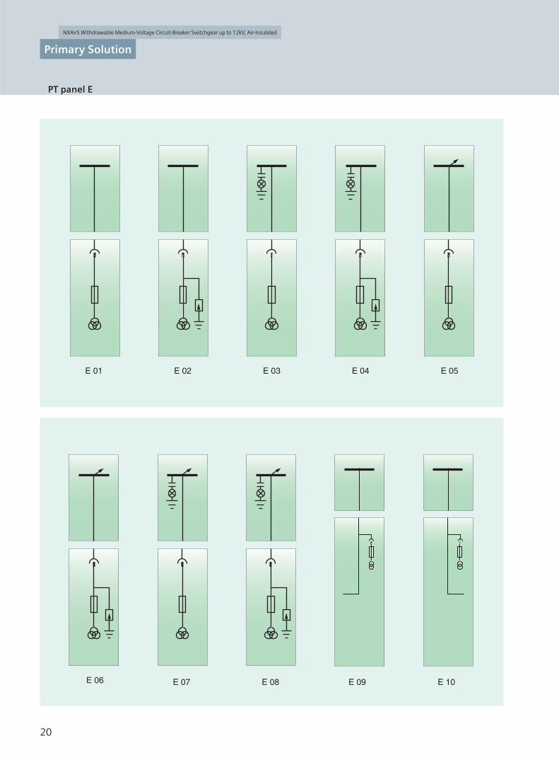
E 01 E 02 E 03 E 04 E 05
E 06 E 08 E 09 E 10E 07
PT panel E
shpm1988.indd 20 2012/11/30 16:17:15
NXAirS Withdrawable Medium-Voltage Circuit-Breaker Switchgear up to 12kV, Air-Insulated
Primary Solution
21
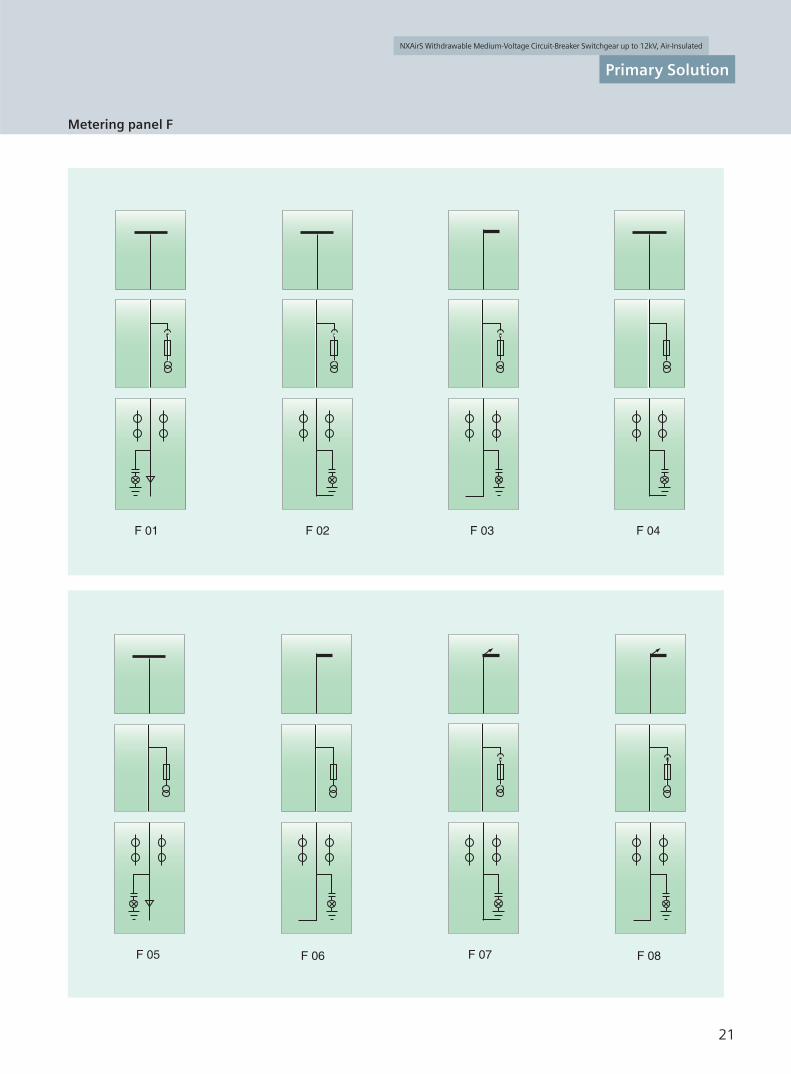
F 01 F 02 F 04F 03
F 05 F 06 F 08F 07
Metering panel F
shpm1988.indd 21 2012/11/30 16:17:15

NXAirS Withdrawable Medium-Voltage Circuit-Breaker Switchgear up to 12kV, Air-Insulated
Primary Solution
22
F 10
G 02 G 03 G 04
F 09
G 01
Metering panel F/Station transformer panel G
shpm1988.indd 22 2012/11/30 16:17:15

NXAirS Withdrawable Medium-Voltage Circuit-Breaker Switchgear up to 12kV, Air-Insulated
Primary Solution
23
H 01 H 02 H 03
I 01 I 02 I 03 I 04 I 05
Special solutions can be provided according to requirement
Notes:
Busbar with earthing switch Busbar with PT
I 01 I 02
Busbar with earthing switch
I 03
Busbar with PT Contactor
I 04 I 05
Cable-connector panel H/Metering panel I
shpm1988.indd 23 2012/11/30 16:17:15

NXAirS Withdrawable Medium-Voltage Circuit-Breaker Switchgear up to 12kV, Air-Insulated
24
Design
1
2
3
4
56
78
9
10
11
12
13
14
15
16
17
18
19
20
21
A Switching-device compartmentB Busbar compartmentC Connection compartmentD Withdrawable circuit-breakerE Low-voltage compartment
Door of low-voltage Protection velayHigh-voltage doorLocking device for high-voltage doorMimic diagram
ON/OFF actuating openings for thecircuit-breaker, opening for spring chargingInspection window to recognize the
CLOSED/OPEN indication of the circuit-breaker, closing spring charged indication andoperating cycle counterDoor knob for opening the high-voltage doorActuating opening to move the switchingdeviceMechanical switch position indicator and actuating opening for the make-proof
123456
7
8
9
10
Pressure release ductBusbarsInsulatorContact boxTransformerBushing-type current transformerCable connection for 4 cables per phaseMake-proof earthing switchLow-voltage plug connectorOperating and interlocking unit for thecircuit-breakerVacuum interruptersContact systemOperating and interlocking unit for moving the circuit-breaker and for earthing
11121313*14*1415161718
192021
40kA Panel, Rated Current 4000A
Features
Integrated mimic diagramRecognition of the respectiveswitch positions for circuitbreakerCLOSED/OPEN, disconnectedposition, earthingswitch CLOSED/OPEN onthe integrated mimic diagramUnambiguous assignment ofactuating openings and controlelements to the correspondingswitch position indicatorsAll switching operationsalways with high-voltagedoor closedErgonomically favorableheight for all control andindicator elementsOption: Verification of safeisolation from supply – offeeder or busbar – by meansof a capacitive voltage detectionsystem with panel frontclosed
Interlocking conditions are satisfied according to GB 3906 IEC 62 271-200 Feeder earthing switchcan only be operated with switching device in disconnectedpositionSwitching device can only bemoved on the movable partwith the associated switching device OPEN and earthingswitch OPENSwitching device can only beoperated in interlocked disconnected or service positionSwitching device can only be operated after high-voltage door closed
Mechanical coding preventsinsertion of switching devicesfor lower rated normalcurrents into panels withhigher rated normal currentsInterlocking of high-voltage door against withdrawable partOption: Electromagneticinterlocks, padlocks
Interlocks
Beyond the specifications ofthe standards
Mechanical padlocks can be installed at operating holes of earthing switch and actuating opening of moving the switching device so as to prevent fault operation
25kA/31.5kA, Rated Current 2500A
11
12
13*
14*
17
18
19
20
2115
16
A
E
D
B
C
1
2
3456
7
89
10
Basic panel design
shpm1988.indd 24 2012/11/30 16:17:16

NXAirS Withdrawable Medium-Voltage Circuit-Breaker Switchgear up to 12kV, Air-Insulated
25
Design
Connection compartment
Low-voltage compartment
High-voltage compartment
Busbar compartment
Current transformer
Pressure relief duct
Panel for 31.5kA/40kA, 3150A with classic circuit breaker
Connection compartment
Low-voltage compartment
High-voltage compartment
Busbar compartment
Current transformer
Pressure relief duct
Panel for 25kA/31.5kA, 1250-2500A with classic circuit breakerand all of the Panels with EP breakers
Connection co
Low-voltage compartment
High-voltage compartment
Busbar compartm
Current transfor
0 2500A with c
Compartments and components
shpm1988.indd 25 2013/1/21 13:15:57

NXAirS Withdrawable Medium-Voltage Circuit-Breaker Switchgear up to 12kV, Air-Insulated
26
Design
Enclosure made of galvanized sheet-steel Pressure release upwards Panel front powder-coated with epoxy resin Shutter operating mechanism separately for
closing and opening the– busbar compartment– connection compartment High-voltage door pressureresistant in the
event of internal arcs in the panel Pressure-resistant partitions to connection and
busbar compartments Metallic ducts on the side for laying control
cables Low-voltage plug connector for connection of
control cables between primary part and secondary part
Switching-device compartment for the different panel versions with
– withdrawable devices:Vacuum circuit-breakerVacuum contactorDisconnector linkWithdrawable metering unit
– Fixed-mounted devices:Disconnection switch
Connection compartment
Enclosure made of galvanized sheet steel. pressure release upwards from pressure rolief duct. Pressure-resistant partitions between conection
and busbar compartment. Earthing busbar. Option: Coupling electrode for
capacitivevoltage detection system. Option: Pressure-resistant floor cover. Option: Post type casting insulating current
transformer. Busbar type casting insulating current
transformer. Option: Back-door structure at the rear of
panel. Option: Earthing switch can be installed at the
rear. The layout instruction can be consulted from Siemens.
Connection from front or rear, primary cables from below or above.
Suitable for connection of:- Single-core XLPE cables up to 4 500mm2
- Three-core cables 3 240mm2
- Incoming copper bar with bushings Arrester- Protect the switchgear against external
overvoltages.
Suitable for rated short-circuit breaking current
with classic breaker
with classic or EP breaker
31.5kA and rated current 3150A
Suitable for rated short-circuit breaking current 31.5kA and rated current 2500A
Switching-device compartment
Introduction of compartments
shpm1988.indd 26 2012/11/30 16:17:42

NXAirS Withdrawable Medium-Voltage Circuit-Breaker Switchgear up to 12kV, Air-Insulated
27
Design
Busbar compartment
- Enclosure made of galvanized sheet steel.- Pressure release upwards.- Bushing disconnection between switchgear and
switchgear.- Busbar adopts flat copper, bolted from panel to panel.- Option: Insulated busbar.- Pressure-resistant partitions between connection
compartment and switching-device compartment, pressure-resistant at the rear wall.
- Option: Busbar earthing switch.- Option: Busbar voltage transformer (fixed installation).- Option: Coupling electrode for capacitive voltage
detection system.- Additional compartment (optional) for busbar
compartment, refer to primary solution.
The structure of busbar compartment with rated current 1250Aand rated short-circuit breaking current 25kA
The structure of busbar compartment with rated current 2500Aand rated short-circuit breaking current 25/31.5kA
The structure of busbar compartment with rated current 3150Aand rated short-circuit breaking current 40kA
Switchgear in marine industry
Switchgear in Marine industry
The marine market can be divided into industrial ships, passenger ships, military ships and platforms due to different using locations, whose operation environment is much worse than the land due to the characters of high salt, high humidity, big temperature gap, vibration, shake and etc. To ensure the operation safety, relevant classification society make quality authentication to switching device used in marine industry. Only the products which pass the audit and gain certification can be used in marine project.The installed circuit-breaker, 3AE-SION passed the environmental test like vibration, high temperature, low temperature etc and related type test, and gained the type recognition certificate. On the base, NXAirS switchgear passed the classification test and got the marine application certificate issued by the classification society. NXAirS can fully meet the requirements of marine operation status. Currently NXAirS switchgear has been already applied in some marine projects.
Introduction of compartments
shpm1988.indd 27 2012/11/30 16:18:01

NXAirS Withdrawable Medium-Voltage Circuit-Breaker Switchgear up to 12kV, Air-Insulated
28
Design
Low-valtage compartment
For accommodation of all protection, control, measuring and metering devicesSeparated safe-to-touch from the high-voltage partAll bus wires are removable and control cables are connected by bolts.Option:Removable bus wires and plug-in-type connection of control cables.Option: Test sockets for capacitive voltage detectionsystem of feeders or busbarOption: Higher low-voltage compartmentLow-voltage cables are flexible and have metal coversConnection of withdrawable part and panel wiring to low- voltage compartment via 64-
core, coded plug connectors
Low-voltage compartment
Door of low-voltage compartment
Introduction of compartments
shpm1988.indd 28 2012/11/30 16:18:17

NXAirS Withdrawable Medium-Voltage Circuit-Breaker Switchgear up to 12kV, Air-Insulated
29
Components
Switch devices
Vacuum circuit breaker for 25/31.5kA, 2500A
Vacuum circuit breaker for 31.5kA, 2500A
EP circuit breakerEP circuit breaker
sion
Circuit breaker
Features
• Corresponding to IEC 62 271-100 and GB 1984-2003
• Meet the regulation reguirements of CCS (China Classifi cation Society) and gain type recognition certifi cate.
• Suitable for all switching duties
• With motor operation and manual operation
• Moving the cassettee of circuit-breaker with manual operation or motor operation.
• 64-pole low-voatage plug connector between circuit-breaker and fi xed part
• Maintenance-free operating mechanisms under normal climatic conditions and max.permissible number of operating cycles
• Contact arms (optional)- special contacts- round contacts
1 64-pole low-voltage pulg connector2 Primary contacts3 "OFF" pushbutton4 Switch position indicator5 "ON" pushbutton6 "Spring charged" indicator7 Hand crank coupling for the spring energy store
8 Operating cycle counter9 Actuating opening to moving mechanism10 Position indicator earthing switch11 Actuating opening earthing switch12 Locking/unlocking of the withdrawable part13 Embedded Pole
shpm1988.indd 29 2012/11/30 16:18:24
NXAirS Withdrawable Medium-Voltage Circuit-Breaker Switchgear up to 12kV, Air-Insulated
30
Components
X1
X1
X1
21 13
1422
21
22
31
31A1
A1
A2
A211
13
1411
12
13
14
21
22
23
24
31
32
33
34
41
42
43
44
51
52
53
54
61
62
63
64
71
72
73
74
81
82
83
84
91
92
93
94
111
112
113
114
121
122
123
12421
22
HG
11-2
507.
eps
HG
11-2
508.
eps
12
13
13
14
14
-K1
-S3
-K1
-S1 -S1
-S6
-S7
-K1
-Y1
-S5
-S12
-Y4
-Y7
-S1
-S1
-R1
33
34A1
A2
A1
A2
D1
43
44
1
2
D2
X0
X1
X0
X1
X0
X1
X0X1
X0
X1
X0
X1
X0
X1
X0
X1
X0
X1
X0
-X0
-X0
2121
21
13
13
14
14
-S3
-S1 -S1
-S1
-S4-Y1
11
12
2222
22
2123
11
12
13
14
21
22
23
24
31
32
33
34
41
42
43
44
51
52
53
54
61
62
63
6424
22
32A1
A1
A1A2
A2
A2
31
A1
D2
22
21
-S21 -K1
-K1-K1
-Y9
-S22
-M1 M1=
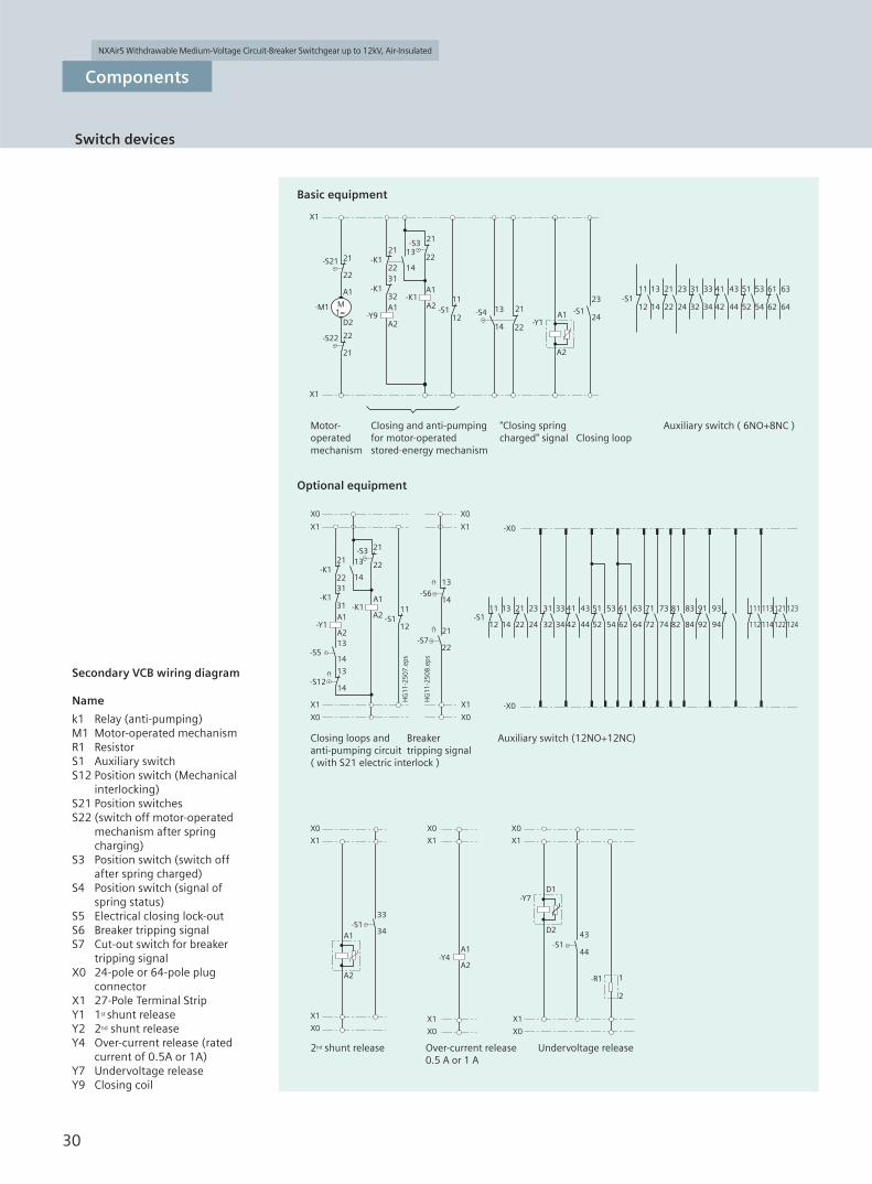
Secondary VCB wiring diagram
Name
k1 Relay (anti-pumping)M1 Motor-operated mechanismR1 ResistorS1 Auxiliary switchS12 Position switch (Mechanical
interlocking)S21 Position switchesS22 (switch off motor-operated
mechanism after spring
charging)S3 Position switch (switch off
after spring charged)S4 Position switch (signal of
spring status)S5 Electrical closing lock-outS6 Breaker tripping signalS7 Cut-out switch for breaker
tripping signalX0 24-pole or 64-pole plug
connectorX1 27-Pole Terminal StripY1 1st shunt releaseY2 2nd shunt releaseY4 Over-current release (rated
current of 0.5A or 1A)Y7 Undervoltage releaseY9 Closing coil
Basic equipment
Optional equipment
Motor-operatedmechanism
Closing loops andanti-pumping circuit( with S21 electric interlock )
2nd shunt release Over-current release0.5 A or 1 A
Undervoltage release
Breakertripping signal
Auxiliary switch (12NO+12NC)
"Closing springcharged" signal
Auxiliary switch ( 6NO+8NC )Closing loop
Closing and anti-pumpingfor motor-operatedstored-energy mechanism
Switch devices
shpm1988.indd 30 2012/11/30 16:18:40

NXAirS Withdrawable Medium-Voltage Circuit-Breaker Switchgear up to 12kV, Air-Insulated
31
Components
kV
kV
kV
mm
max. A
max. kA
max. kA/s
kA
kA
A
ms
ms
ms
ms
ms
%
%
W
W
s
V
%
Vacuum circuit-breaker
Type
Rated voltage
Rated power frequency withstand voltage
Rated lightning impulse withstand voltage
Rated operating sequence
Pole-centre distance
Rated current
Rated short-circuit breaking current
Rated short-circuit duration
Short-circuit current operating cycles
Rated current operating cycle
Rated short-circuit making current maximum
Rated peak withstand current
Rated capacitor bank making and breaking capacity
Break time
Closing time
Opening time
Arcing time
Close / open now synchronization
1st shunt release tripping voltage range
Closing solenoid tripping voltage range
1st shunt release power consumption
Closing solenoid power consumption
Spring charging time
Charging motor voltage
Charging motor operating voltage range
3AE
12
42
75
O-0.3s-CO-180s-CO( 31.5kA),O-180s-CO-180s-CO(40kA)
210
4000**
40
40kA/4s
274(according GB1984-2003 IEC62271-100)
30000
110
110
630
80
75
< 65
< 15
2
65%-110%
75%-110%
200(110V) 160(220V)
200(110V) 160(220V)
<15
DC110, DC220, AC110, AC220
85%-110%
3AE vacuum circuit-breaker technical data*
*: refer to 3AE Catalogue
**:compelling forced ventilation.
Switch devices
shpm1988.indd 31 2012/11/30 16:18:42

NXAirS Withdrawable Medium-Voltage Circuit-Breaker Switchgear up to 12kV, Air-Insulated
32
Components
Vaccum contactor-fuse
combination equipment
features:
- In accordance with IEC60470
and GB/T14808-2001.
- With raccum contactor imported
from Germany.
- Optional of electric keeping and
mechanical keeping.
- Combined parts and fi xed parts
are connected with 64pole low
voltage plug
1 64-pole low voltage Plug
2 emergency " open " button
3 operation hole of cassette
4 contactor position indicator
5 operation counter
6 fuse status indicator
7 contactor
–
Switchgear devices
shpm1988.indd 32 2012/12/4 13:47:58

NXAirS Withdrawable Medium-Voltage Circuit-Breaker Switchgear up to 12kV, Air-Insulated
Technical data
33
note: handcart locates in test position. contactor open and fuse off position.
Vacuum contactor
fuse status
Electric keeping
mechanical keeping
open
test position
operating position
cassette position switch
Close
Components
Secondary Vaccum contactor-fuse
Combination equipment
wiring diagram
Switchgear devices
X1 terminal of contactor
X0 64 Pins Plug
S11, S12 fuse open/closing
position switch
SL cassette poisition switch
PC MCF
R resistor
K2S Triping coil
K1E, K2E Auxiliary switch
K1M closing coil
FUL1~FUL3 HV fuse
shpm1988.indd 33 2013/1/21 13:16:56

NXAirS Withdrawable Medium-Voltage Circuit-Breaker Switchgear up to 12kV, Air-Insulated
34
Components
3TL6 vacuum coutactor technical data
No. Parameter Unit Value Value
1 Rated voltage kV 7.2 12
2 Rated frequency Hz 50 50
3Rated insulation level
Rated power frequency with stand vlotage1min
kV
32 42
Rated lightning impulse withstand voltage 60 75
Secondang control and secondary circuit withstand voltage 1min
2 2
4 Rated current A 450 400
5 Rated short-circuit breaking current kA 3.6 3.2
6 Limitation breaking current kA 5 4.5
7 Rated making current kA 4.5 4
8 Rated short-time withstand current kA 8 8
9 Rated peak withstand current kA 20 20
10 Rated short-circuit duration s 1 1
11 Main circuit resistance 180 180
12 Rated operating frequenyelectrical maintanance
times/h1200 600
menhanison maintanance 60 300
13 types for use AC-4 AC-4
14 Mechanical lifetimeelectrical keeping
times3, 000, 000 1, 000,000
mechanical keeping 100, 000 100, 000
Switch devices
shpm1988.indd 34 2012/12/4 13:54:17

NXAirS Withdrawable Medium-Voltage Circuit-Breaker Switchgear up to 12kV, Air-Insulated
35
Components
Switch devices
Vacuum contactor-fuse combination equipment and technical data
No. Parameter Unit Value number
1 Rated voltage kV 7.2 12
2 Rated frequency Hz 50 50
3Rated insulation level
Rated power frequency with stand vlotage1min
kV
32 42
Rated lightning impulse withstand voltage 60 75
Secondang control and secondary circuit withstand voltage 1min
2 2
4 Rated current ( depend on fuse current ) A 250 160
5Rated expected short-circuit breaking current ( depend on fuse current )
kA 50 50
6 Rated short-time withstand current kA/s 8/1 8/1
7 Rated peak withstand current kA 20 20
8 Rated short-circuit duration s 1 1
9 Rated take-over current kA 3.6 3.2
10 Rated contact stroke mm 5.5-6.5 5.5~6.5
11 Break time ( with/without mechanical lock ) ms 25-95/25~130 25~95/25~130
12 Closing time ms 150 150
13 operating frequency ( with/without mechanical lock ) /h 60/1200 300/600
14 Main circuit resistance ( fuse displaced with copper rod ) 280 300
15 Pole-center distance mm 150 2 150 2
shpm1988.indd 35 2012/12/4 13:54:58

NXAirS Withdrawable Medium-Voltage Circuit-Breaker Switchgear up to 12kV, Air-Insulated
36
Components
Type Voltage Rating
SC9 SC10 10/0.4kV 10kV 30, 50, 80, 100kVA
-Suitable to current transformer with different rated current
Transformer Features:
- In accordance with GB6450 and GB/T10228- Resin cast dry-type transformer.
Voltage transformerFeatures
- In accordance with GB1207 and IEC 60186- Casting insulting transformer.
- In accordance with GB11032 and IEC 60099-4
Surge arresterFeatures
- According to GB1208 and IEC 60044-1- Post type casting insulating transformer. Busbar type casting insulating transformer.- Various ratio and high precision
Current transformerFeatures
Switch devices
shpm1988.indd 36 2013/1/29 13:50:12

NXAirS Withdrawable Medium-Voltage Circuit-Breaker Switchgear up to 12kV, Air-Insulated
37
Standards
Panel NXAir S
IP3XD
Degree of protection of the enclosure optional IP4X
IP51
Degree of protection of the enclosure IP3XD
with ventilation IP4X
Degree of protection of compartments IP2X
Aseismic capacity
NXAirS switchgear types are tested in accordance with internationally accepted requirements.
Terms
Earthing switches are earthing switches according to GB 1985 / IEC 62 271-102
Internal arc classification
Safety of operating personnel ensured by tests to verify internal arc classification
Internal arc tests performed in accordance with IEC 62 271-200 / GB/T 3906-2006
NXAirS comply with the internal arc classification: IAC A FLR up to 40 kA, 1s, providing for maximum personal safety of switchgear accessible from all sides.
Definitions of criteria:– Acceptance criterion 1 Covers and doors
remain closed. Limited deformations are accepted.
– Acceptance criterion 2 No fragmentation of the enclosure. No projection of small parts above 60 g weight.
– Acceptance criterion 3 No holes in the accessible sides up to a height of 2 m.
– Acceptance criterion 4 Indicators do not ignite due to the effect of hot gases.
– Acceptance criterion 5 The enclosure remains connected to its earthing parts.
This switchgear up to 40 kA is designed with confinement to internal arcs going beyond the scope of the mentioned standards; that means that in the event of an internal fault (arc) in a particular compartment, the effects of the arc remain confined to that compartment:
– No burn-through of partitions to adjacent compartments
– No burn-through of partition walls to adjacent panels
– Pressure-resistant walls between adjacent compartments and panels.
The confinement of an internal arc prevents
– Restrike of an arc fault on live parts in adjacent compartments
– Impermissible deformation of partitions.
Current-carrying capacity
According to GB 3906 / IEC 60 694 / GB/T11022 / IEC 62271-200 current carrying capacities refer to the following ambient temperatures:
– Maximum of 24-hour average temperature + 35 C
– Maximum + 40 C
NXAirS can be used under the following climate classes and ambient conditions with additional measures.
Ambient conditions– Natural foreign materials– Chemical active pollutants.– Small animals. Climate classes1.Ambient air temperture: -15 C~+40 C2.Site altitude:1000m and below3.Relative humidity:max.95% for 24
hours,max.90% for one month.4.Earthquake intensity is smaller than
magnitude 8.5.Site without fire, blast danger,serious dirt
and severe shocks. The climate classes are classified according
to IEC 60721-3-3 and GB 3906-2006.
The current-carrying capacity of the panels and busbars depends on the ambient temperature outside the enclosure.
Protection against solid foreign bodies, electric shock and ingrevss of water
NXAirS switchgear types confirm to the following protection degree
Protection degree
Standards, specifi cations, guidelines
shpm1988.indd 37 2012/11/30 16:18:50

NXAirS Withdrawable Medium-Voltage Circuit-Breaker Switchgear up to 12kV, Air-Insulated
Technical data
38
IEC standard GB standard
Switchgear NXAirS IEC 60 694 GB/T 11022
IEC 62 271-200 GB 3906
Devices Circuit-breaker IEC 62 271-100 GB 1984
Vacuum contactor IEC 60 470 GB 14808
Disconnector and earthing switch IEC 62 271-102 GB 1985
disconnector IEC 60 265-1 GB 1985
disconnector / IEC 62 271-105 GB 16926
fuse combination
HV HRC fuses IEC 60 282 GB 15166.2
Voltage detection device IEC 61 243-5
Degree of - IEC 60 529 GB/T 4208protection
Insulation - IEC 60 071 GB 311.1
Transformers Current transformer IEC 60 044-1 GB 1208
Voltage transformer IEC 60 044-2 GB 1207
Installation - IEC 61 936-1 GB 50254-GB 50259
Standards
The switchgear complies withthe relevant standards andspecifications applicable atthe time of type tests.
Overview of standards
Standards, specifi cations, guidelines
shpm1988.indd 38 2012/11/30 16:18:50
NXAirS Withdrawable Medium-Voltage Circuit-Breaker Switchgear up to 12kV, Air-Insulated
Technical data
39
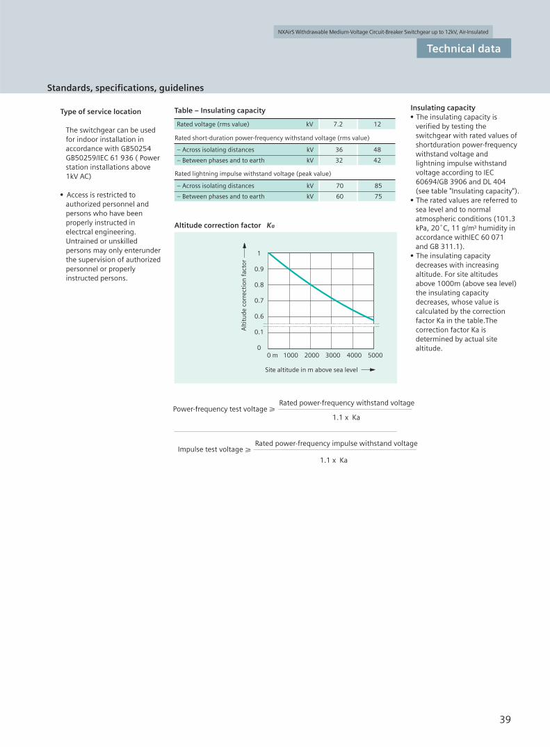
Insulating capacityThe insulating capacity is verified by testing the switchgear with rated values of shortduration power-frequency withstand voltage and lightning impulse withstand voltage according to IEC 60694/GB 3906 and DL 404 (see table "Insulating capacity").The rated values are referred to sea level and to normal atmospheric conditions (101.3 kPa, 20 C, 11 g/m3 humidity in accordance withIEC 60 071 and GB 311.1).The insulating capacity decreases with increasing altitude. For site altitudes above 1000m (above sea level) the insulating capacity decreases, whose value is calculated by the correction factor Ka in the table.The correction factor Ka is determined by actual site altitude.
Table – Insulating capacity
Altitude correction factor Ka
Rated short-duration power-frequency withstand voltage (rms value)
Rated lightning impulse withstand voltage (peak value)
Rated voltage (rms value) kV 7.2 12
– Across isolating distances kV 36 48
– Between phases and to earth kV 32 42
– Across isolating distances kV 70 85
– Between phases and to earth kV 60 75
1
0.9
0.8
0.7
0.6
0.1
00 m 1000 2000 3000 4000 5000
Type of service location
The switchgear can be used for indoor installation in accordance with GB50254 GB50259/IEC 61 936 ( Power station installations above 1kV AC)
Access is restricted to authorized personnel and persons who have been properly instructed in electrcal engineering. Untrained or unskilled persons may only enterunder the supervision of authorized personnel or properly instructed persons.
Alt
itu
de c
orre
ctio
n f
acto
r
Site altitude in m above sea level
Power-frequency test voltage Rated power-frequency withstand voltage
1.1 x Ka
1.1 x Ka
Impulse test voltageRated power-frequency impulse withstand voltage
Standards, specifi cations, guidelines
shpm1988.indd 39 2012/11/30 16:18:51
: XXXXXXXXXXXXXXX
XXXX-XXXXXXX-XXXXX
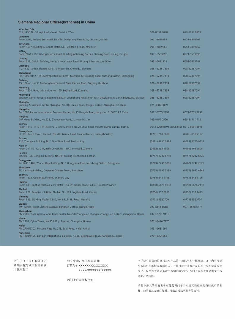
Siemens Regional Of ces(branches) in China
Xi’an Rep.Offi cF28, HIBC, No.33 Keji Road, Gaoxin District, Xi'an 029-8831 9898 029-8833 8818
LanZhouRoom2206, Jinjiang Sun Hotel, No.589, Donggang West Road, Lanzhou, Gansu 0931-8885151 0931-8810707
YinChuanRoom 1507, Building A, Apollo Hotel, No.123 Beijing Road, Yinchuan 0951-7869866 0951-7869867
XiNingRoom21613,16F, Ziheng International, Building A Xinning Garden, Xinning Road, Xining, Qinghai 0971-5503390 0971-5503390
UrumqiRoom 918, Guibin Building, Hongfu Hotel, Wuyi Road, Urumqi Infrastructure&Cites 0991-5821122 0991-5815387
Chengdu1-2F, C6, Tianfu Software Park, Tianhuaer Lu, Chengdu, Sichuan 028 - 6238 7339 028-62387094
ChongqingRm.1809-1812, 18/F, Metropolitan business , Mansion, 68 Zourong Road, Yuzhong District, Chongqing 028 - 6238 7339 028-62387094
Guiyang 15th Floor, Unit C, Fuzhong International Plaza Xinhua Road, Guiyang, Guizhou 028 - 6238 7339 028-62387094
KunmingRoom 1204, Hongta Mansion No. 155, Beijing Road, Kunming 028 - 6238 7339 028-62387094
MianyangBusiness Center Meeting Room of Sichuan Changhong Hotel, High Tech Development Zone, Mianyang, Sichuan 028 - 6238 7339 028-62387094
ShanghaiBuilding A, Siemens Center Shanghai, No.500 Dalian Road, Yangpu District, Shanghai, P.R.China 021-3889 3889
HangzhouRm.1505,Jiahua International Business Center, No.15 Hangda Road, Hangzhou 310007, P.R.China 0571-8765 2999 0571-8765 2998
Nanjing18F Metro Building, No.228, Zhongshan Road, Xuanwu District 025-8456 0550 025-8451 1612
SuzhouRoom 1115~1119 11F ,National Grand Mansion No.2 Suhua Road, Industrial Area Jiangsu Suzhou 0512-6288 8191 (ext.8316) 0512-6661 4898
Guangzhou8F-10F, Teem Tower, Teemall, No.208 Tianhe Road, Tianhe District, Guangzhou City (020) 3718 2888 (020) 3718 2107
Fuzhou21F, Zhongyin Building, No.136 of Wusi Road, Fuzhou City (0591) 8750 0888 (0591) 8750 0333
XiamenRoom 2111-2112, 21F, Bank Center, No.189 Xiahe Road, Xiamen. (0592) 268 5508 (0592) 268 5505
FoshanBlock K, 19F, Dongjian Building, No.38 Fenjiang South Road, Foshan. (0757) 8232 6710 (0757) 8232 6720
DongguanRm1403-1405, Winner Way Building, No.1 Hongyuan Road, Nancheng District, Dongguan. (0769) 2240 9881 (0769) 2242 2575
Shenzhen9F, Hantang Building, Overseas Chinese Town, Shenzhen. (0755) 2693 5188 (0755) 2693 4245
ShantouRoom 1502, Golden Gulf Hotel, Shantou City (0754) 848 1196 (0754) 848 1195
HaikouRoom 803, Baohua Harbour View Hotel , No.69, Binhai Road, Haikou, Hainan Province (0898) 6678 8038 (0898) 6678 2118
ZhuhaiRoom 229, Paradise Hill Hotel Zhuhai, No. 193 Jingshan Road, Zhuhai. (0756) 337 0869 (0756) 332 4473
NanningRoom 935, 9F, King Wealth C.B.D, No. 63, Jin Hu Road, Nanning. (0771) 5520700 (0771) 5520701
Wuhan19F Jianyin Tower, Jianshe Avenue, Jianghan District, Wuhan,Hubei 027-8548 6688 027 - 8548 6777
ZhengzhouRM.2506, Yuda International Trade Center, No.220 Zhongyuan zhonglu, Zhongyuan District, Zhengzhou, Henan 0371-6771 9110
HunanRM.2101, Cyber Times, No.456 Wuyi Avenue, Changsha, Hunan 0731-8446 7770
HefeiRM.2701/2702, Fortune Plaza No.278, Suixi Road, Hefei, Anhui 0551-5681299
NanchangRM.1403/1405, Jiangxin International Building, No.88, Beijing west road, Nanchang, Jiangxi 0791-6304866
shpm1988.indd 40 2013/1/31 9:57:14