ny-series ipc operating systems and software utilities manual
TRANSCRIPT

Industrial PC PlatformNY-seriesIndustrial PC
Operating Systems and Software Utilities Manual
NYB££-££0NYB££-££1NYB££-££2NYB££-££3NYB££-££4NYP££-££0NYP££-££1NYP££-££2NYP££-££3NYP££-££4
W616-E2-04
NOTEAll rights reserved. No part of this publication may be reproduced, stored in a retrieval system, ortransmitted, in any form, or by any means, mechanical, electronic, photocopying, recording, or other-wise, without the prior written permission of OMRON.No patent liability is assumed with respect to the use of the information contained herein. Moreover,because OMRON is constantly striving to improve its high-quality products, the information containedin this manual is subject to change without notice. Every precaution has been taken in the preparationof this manual. Nevertheless, OMRON assumes no responsibility for errors or omissions. Neither isany liability assumed for damages resulting from the use of the information contained in this publica-tion.
Trademarks• Sysmac and SYSMAC are trademarks or registered trademarks of OMRON Corporation in Japan
and other countries for OMRON factory automation products.• Windows is a registered trademark of Microsoft Corporation in the USA and other countries.
• The SD and SDHC logos are trademarks of SD-3C, LLC.
• CFAST is a registered trademark of CompactFlash Association.• Intel, the Intel Logo, Celeron and Intel Core are trademarks of Intel Corporation in the U.S. and/or
other countries.Other company names and product names in this document are the trademarks or registered trade-marks of their respective companies.
CopyrightsMicrosoft product screen shots reprinted with permission from Microsoft Corporation.

IntroductionThank you for purchasing the Industrial PC.This manual contains information that is necessary to use the Industrial PC (hereafter also namedIPC). Please read this manual and make sure you understand the functionality and performance of theIPC before attempting to use it.Keep this manual in a safe place where it will be available for reference during operation.
Intended AudienceThis manual is intended for the following personnel, who must also have knowledge of software pro-gramming (a software engineer or the equivalent).• Personnel in charge of introducing Factory Automation systems.• Personnel in charge of designing Factory Automation systems.• Personnel in charge of software design for Factory Automation systems.• Personnel in charge of installing and maintaining and programming Factory Automation systems.• Personnel in charge of managing Factory Automation systems and facilities.
Applicable ProductsThis manual covers following Industrial PC products:
Product ModelIndustrial Box PC NYB££Industrial Panel PC NYP££
Additional Information
Refer to 1-4 Product Configuration on page 1-5 for configuration details.
Introduction
1NY-series Industrial PC Operating Systems and Software Utilities Manual (W616)

Introduction
2 NY-series Industrial PC Operating Systems and Software Utilities Manual (W616)

Sections in this Manual
Sections in this Manual
3NY-series Industrial PC Operating Systems and Software Utilities Manual (W616)
Operating Procedures
Specifications
Installation
Software
System Configurations
Overview1
2
3
4
5
6
1
2
3
4
6
5
1
7
7
Appendices
Maintenance
A
A

CONTENTSIntroduction .............................................................................................................. 1
Intended Audience...........................................................................................................................................1Applicable Products .........................................................................................................................................1
Sections in this Manual ........................................................................................... 3
Manual Information.................................................................................................. 8Page Structure.................................................................................................................................................8Special Information ..........................................................................................................................................9
Terms and Conditions Agreement........................................................................ 10Warranty and Limitations of Liability ..............................................................................................................10Application Considerations ............................................................................................................................ 11Disclaimers ....................................................................................................................................................12
Safety Precautions................................................................................................. 13
Precautions for Safe Use ...................................................................................... 14
Precautions for Correct Use ................................................................................. 15
Regulations and Standards .................................................................................. 16Conformance to EU Directives ......................................................................................................................16Conformance to KC Certification ...................................................................................................................17Conformance to UL and CSA Standards.......................................................................................................17Software Licenses and Copyrights ................................................................................................................17
Related Manuals..................................................................................................... 18Related Industrial PC Manuals ......................................................................................................................18Industrial Monitor Manual ..............................................................................................................................18
Terminology and Abbreviations ........................................................................... 19Industrial PC Platform ...................................................................................................................................19Software.........................................................................................................................................................19Hardware ......................................................................................................................................................20
Revision History..................................................................................................... 21
Section 1 Overview1-1 Intended Use .........................................................................................................................1-21-2 Software Features..................................................................................................................1-31-3 ID Information Label ..............................................................................................................1-41-4 Product Configuration...........................................................................................................1-5
1-4-1 Product Configuration Box PC ....................................................................................................1-51-4-2 Product Configuration Panel PC .................................................................................................1-7
1-5 Overall Setup Procedure .......................................................................................................1-9
CONTENTS
4 NY-series Industrial PC Operating Systems and Software Utilities Manual (W616)

Section 2 System Configurations2-1 Configuration for NYB and NYP ...........................................................................................2-2
Section 3 Software3-1 Windows Operating System .................................................................................................3-3
3-1-1 Determine Your Version of the Windows Operating Systems .....................................................3-3
3-2 Overview IPC Support Software for Windows ....................................................................3-43-3 Industrial PC Support Utility ................................................................................................3-5
3-3-1 Industrial PC Support Utility Overview ........................................................................................3-63-3-2 Product Information Tab .............................................................................................................3-73-3-3 System Status Tab ......................................................................................................................3-83-3-4 HW RAID Tab..............................................................................................................................3-93-3-5 Compatibility..............................................................................................................................3-113-3-6 Installation .................................................................................................................................3-113-3-7 Startup.......................................................................................................................................3-113-3-8 Messages..................................................................................................................................3-123-3-9 Logging .....................................................................................................................................3-12
3-4 Industrial Monitor Utility .....................................................................................................3-133-4-1 Industrial Monitor Utility Overview.............................................................................................3-133-4-2 Compatibility..............................................................................................................................3-183-4-3 Installation .................................................................................................................................3-183-4-4 Startup.......................................................................................................................................3-183-4-5 Configuration.............................................................................................................................3-193-4-6 Messages..................................................................................................................................3-193-4-7 Logging .....................................................................................................................................3-19
3-5 Industrial Monitor Brightness Utility .................................................................................3-203-5-1 Industrial Monitor Brightness Utility Overview ..........................................................................3-203-5-2 Compatibility..............................................................................................................................3-213-5-3 Installation .................................................................................................................................3-213-5-4 Startup.......................................................................................................................................3-213-5-5 Configuration.............................................................................................................................3-213-5-6 Logging .....................................................................................................................................3-22
3-6 Rescue Disk Creator and Utility .........................................................................................3-233-6-1 Overview ...................................................................................................................................3-233-6-2 Compatibility..............................................................................................................................3-243-6-3 Installation .................................................................................................................................3-263-6-4 Startup.......................................................................................................................................3-273-6-5 Messages..................................................................................................................................3-27
3-7 Industrial PC Tray Utility ....................................................................................................3-313-7-1 Industrial PC Tray Utility Overview............................................................................................3-313-7-2 Features ....................................................................................................................................3-313-7-3 Menu .........................................................................................................................................3-323-7-4 About the Industrial PC Tray Utility ...........................................................................................3-323-7-5 Status Indicators on Icons.........................................................................................................3-333-7-6 Compatibility..............................................................................................................................3-333-7-7 Installation .................................................................................................................................3-333-7-8 Startup.......................................................................................................................................3-34
3-8 Power Attendant Lite Utility ................................................................................................3-353-8-1 Power Attendant Lite Utility Overview .......................................................................................3-353-8-2 Features ....................................................................................................................................3-353-8-3 Compatibility..............................................................................................................................3-353-8-4 Installation .................................................................................................................................3-363-8-5 Configuration.............................................................................................................................3-36
3-9 Software for Developers......................................................................................................3-383-9-1 Overview of IPC Developer Software for Windows...................................................................3-383-9-2 Industrial PC System API .........................................................................................................3-39
CONTENTS
5NY-series Industrial PC Operating Systems and Software Utilities Manual (W616)

3-9-3 Industrial Monitor API ...............................................................................................................3-40
Section 4 Specifications4-1 Software Specifications .......................................................................................................4-2
4-1-1 Compatible Operating Systems ..................................................................................................4-24-1-2 Available Windows Operating Systems.......................................................................................4-3
Section 5 Installation5-1 Install Software ......................................................................................................................5-2
5-1-1 Internet Browser..........................................................................................................................5-25-1-2 Firewall ........................................................................................................................................5-35-1-3 Anti-virus Software ......................................................................................................................5-35-1-4 Drivers and Custom Software .....................................................................................................5-45-1-5 Activate Windows........................................................................................................................5-45-1-6 Customize Windows....................................................................................................................5-4
5-2 Install Support Software........................................................................................................5-55-2-1 Overview IPC Support Software for Installation ..........................................................................5-5
5-3 Create Backup and Repair Media .........................................................................................5-6
Section 6 Operating Procedures6-1 React to Product Messages..................................................................................................6-26-2 React to Windows Messages................................................................................................6-3
Section 7 Maintenance7-1 Preventive Maintenance........................................................................................................7-2
7-1-1 Preventive Maintenance Schedule..............................................................................................7-27-1-2 Keep Software Updated ..............................................................................................................7-27-1-3 Create Backup and Repair Data .................................................................................................7-37-1-4 Check the Storage Device Status .............................................................................................7-157-1-5 Check the Backup and Repair Media........................................................................................7-17
7-2 Corrective Maintenance ......................................................................................................7-197-2-1 Warning and Error Messages....................................................................................................7-197-2-2 Restore and Repair Data ..........................................................................................................7-207-2-3 Allocate a Drive in Windows......................................................................................................7-287-2-4 Windows Event Viewer..............................................................................................................7-297-2-5 Windows Low on Memory .........................................................................................................7-317-2-6 Windows Blue Screens .............................................................................................................7-327-2-7 Correct Display Functionality when Nothing is Displayed .........................................................7-327-2-8 Correct Touchscreen Functionality ............................................................................................7-337-2-9 Correct a RAID Array ................................................................................................................7-37
AppendicesA-1 Customize Windows ............................................................................................................. A-2
A-1-1 Enhanced Write Filter................................................................................................................. A-2A-1-2 File-Based Write Filter................................................................................................................ A-3A-1-3 Unified Write Filter...................................................................................................................... A-5A-1-4 Trusted Platform Module ............................................................................................................ A-6
CONTENTS
6 NY-series Industrial PC Operating Systems and Software Utilities Manual (W616)

Index
CONTENTS
7NY-series Industrial PC Operating Systems and Software Utilities Manual (W616)

Manual InformationThis section provides information about this manual.
Page StructureThe following page structure is used in this manual.
A
B
C
C D
E
F
B
C
H
5 Installation
5 - 3NY-series User's Manual (W555)
5-1
Un
pa
ck
5
5-1
-1 U
np
ack P
roce
du
re
G
5-1 Unpack
This section provides details on how to unpack the Industrial Panel PC.
5-1-1 Unpack Procedure
1 Check the package for damage.
If there is any visible damage:
• Take photos of the package and save them.
• Inform your supplier immediately.
2 Open the package.
Ensure not to damage the contents.
3 Ensure that all items are present.
Additional Information
Refer to 5-1-2 Items Supplied with the Product for the items supplied.
Note: This illustration is provided as a sample. It will not literally appear in this manual.
Item Explanation Item ExplanationA Level 1 heading E Special InformationB Level 2 heading F Manual nameC Level 3 heading G Page tab with the number of the main sectionD Step in a procedure H Page number
Manual Information
8 NY-series Industrial PC Operating Systems and Software Utilities Manual (W616)

Special InformationSpecial information in this manual is classified as follows:
Precautions for Safe Use
Precautions on what to do and what not to do to ensure safe usage of the product.
Precautions for Correct Use
Precautions on what to do and what not to do to ensure proper operation and performance.
Additional Information
Additional information to read as required.This information is provided to increase understanding or make operation easier.
Version Information
Information on differences in specifications and functionality between different versions.
Manual Information
9NY-series Industrial PC Operating Systems and Software Utilities Manual (W616)

Terms and Conditions Agreement
Warranty and Limitations of Liability
WARRANTY• The warranty period for the Software is one year from the date of purchase, unless otherwise
specifically agreed.• If the User discovers defect of the Software (substantial non-conformity with the manual), and return
it to OMRON within the above warranty period, OMRON will replace the Software without charge byoffering media or download from OMRON’s website. And if the User discovers defect of mediawhich is attributable to OMRON and return it to OMRON within the above warranty period, OMRONwill replace defective media without charge. If OMRON is unable to replace defective media orcorrect the Software, the liability of OMRON and the User’s remedy shall be limited to the refund ofthe license fee paid to OMRON for the Software.
LIMITATION OF LIABILITY• THE ABOVE WARRANTY SHALL CONSTITUTE THE USER’S SOLE AND EXCLUSIVE
REMEDIES AGAINST OMRON AND THERE ARE NO OTHER WARRANTIES, EXPRESSED ORIMPLIED, INCLUDING BUT NOT LIMITED TO, WARRANTY OF MERCHANTABILITY ORFITNESS FOR PARTICULAR PURPOSE. IN NO EVENT, OMRON WILL BE LIABLE FOR ANYLOST PROFITS OR OTHER INDIRECT, INCIDENTAL, SPECIAL OR CONSEQUENTIALDAMAGES ARISING OUT OF USE OF THE SOFTWARE.
• OMRON SHALL HAVE NO LIABILITY FOR DEFECT OF THE SOFTWARE BASED ONMODIFICATION OR ALTERNATION TO THE SOFTWARE BY THE USER OR ANY THIRD PARTY.OMRON SHALL NOT BE RESPONSIBLE AND/OR LIABLE FOR ANY LOSS, DAMAGE, OREXPENSES DIRECTLY OR INDIRECTLY RESULTING FROM THE INFECTION OF OMRONPRODUCTS, ANY SOFTWARE INSTALLED THEREON OR ANY COMPUTER EQUIPMENT,COMPUTER PROGRAMS, NETWORKS, DATABASES OR OTHER PROPRIETARY MATERIALCONNECTED THERETO BY DISTRIBUTED DENIAL OF SERVICE ATTACK, COMPUTERVIRUSES, OTHER TECHNOLOGICALLY HARMFUL MATERIAL AND/OR UNAUTHORIZEDACCESS.
• OMRON SHALL HAVE NO LIABILITY FOR SOFTWARE DEVELOPED BY THE USER OR ANYTHIRD PARTY BASED ON THE SOFTWARE OR ANY CONSEQUENCE THEREOF.
Terms and Conditions Agreement
10 NY-series Industrial PC Operating Systems and Software Utilities Manual (W616)
Application Considerations
APPLICABLE CONDITIONSA USER SHALL NOT USE THE SOFTWARE FOR ANY PURPOSE THAT IS NOT PROVIDED INTHIS MANUAL OR IN A RELATED HARDWARE USER'S MANUAL.
Suitability of UseOmron Companies shall not be responsible for conformity with any standards, codes or regulationswhich apply to the combination of the Product in the Buyer’s application or use of the Product. AtBuyer’s request, Omron will provide applicable third party certification documents identifying ratingsand limitations of use which apply to the Product. This information by itself is not sufficient for acomplete determination of the suitability of the Product in combination with the end product, machine,system, or other application or use. Buyer shall be solely responsible for determining appropriatenessof the particular Product with respect to Buyer’s application, product or system. Buyer shall takeapplication responsibility in all cases.
NEVER USE THE PRODUCT FOR AN APPLICATION INVOLVING SERIOUS RISK TO LIFE ORPROPERTY OR IN LARGE QUANTITIES WITHOUT ENSURING THAT THE SYSTEM AS A WHOLEHAS BEEN DESIGNED TO ADDRESS THE RISKS, AND THAT THE OMRON PRODUCT(S) ISPROPERLY RATED AND INSTALLED FOR THE INTENDED USE WITHIN THE OVERALLEQUIPMENT OR SYSTEM.
Programmable Products• Omron Companies shall not be responsible for the user’s programming of a programmable Product,
or any consequence thereof.• Omron Companies shall not be responsible for the operation of the user accessible operating sys-
tem (e.g. Windows, Linux), or any consequence thereof.
Terms and Conditions Agreement
11NY-series Industrial PC Operating Systems and Software Utilities Manual (W616)

Disclaimers
Performance DataData presented in Omron Company websites, catalogs and other materials is provided as a guide forthe user in determining suitability and does not constitute a warranty. It may represent the result ofOmron’s test conditions, and the user must correlate it to actual application requirements. Actual per-formance is subject to the Omron’s Warranty and Limitations of Liability.
Change in Software SpecificationsThe software specifications and accessories may be changed at any time based on improvements andother reasons.
Errors and OmissionsInformation presented by Omron Companies has been checked and is believed to be accurate; how-ever, no responsibility is assumed for clerical, typographical or proofreading errors or omissions.
Terms and Conditions Agreement
12 NY-series Industrial PC Operating Systems and Software Utilities Manual (W616)

Safety Precautions
Information is available in related manuals.• For NYB£ refer to NY-series Industrial Box PC Hardware User’s Manual (Cat. No. W553)• For NYP£ refer to NY-series Industrial Panel PC Hardware User’s Manual (Cat. No. W555)
Safety Precautions
13NY-series Industrial PC Operating Systems and Software Utilities Manual (W616)

Precautions for Safe Use
Information is available in related manuals.• For NYB£ refer to NY-series Industrial Box PC Hardware User’s Manual (Cat. No. W553)• For NYP£ refer to NY-series Industrial Panel PC Hardware User’s Manual (Cat. No. W555)
Precautions for Safe Use
14 NY-series Industrial PC Operating Systems and Software Utilities Manual (W616)
Precautions for Correct Use
Information is available in related manuals.• For NYB£ refer to NY-series Industrial Box PC Hardware User’s Manual (Cat. No. W553)• For NYP£ refer to NY-series Industrial Panel PC Hardware User’s Manual (Cat. No. W555)
Precautions for Correct Use
15NY-series Industrial PC Operating Systems and Software Utilities Manual (W616)

Regulations and Standards
Conformance to EU DirectivesThe Industrial PC complies with EU Directives. To ensure that the machine or device in which the In-dustrial PC is used complies with EU Directives, the following precautions must be observed:• The Industrial PC must be installed within a control panel.• The Industrial PC that complies with EU Directives also conforms to the Common Emission Stand-
ard. Radiated emission characteristics (10-m regulations) may vary depending on the configurationof the control panel used, other devices connected to the control panel, wiring, and other conditions.You must therefore confirm that the overall machine or equipment in which the Industrial PC is usedcomplies with EU Directives.
• This is a Class A product (for industrial environments). In a residential environment, it may causeradio interference. If radio interference occurs, the user may be required to take appropriate meas-ures.
Applicable DirectiveEMC Directive
EMC DirectiveOMRON devices that comply with EU Directives also conform to the related EMC standards so thatthey can be more easily built into other devices or the overall machine. The actual products have beenchecked for conformity to EMC standards.Applicable EMC (Electromagnetic Compatibility) standards are as follows:• EMS (Electromagnetic Susceptibility): EN 61131-2• EMI (Electromagnetic Interference): EN 61131-2 (Radiated emission: 10-m regulations)Whether the products conform to the standards in the system used by the customer, however, must bechecked by the customer. EMC-related performance of the OMRON devices that comply with EU Di-rectives will vary depending on the configuration, wiring, and other conditions of the equipment or con-trol panel on which the OMRON devices are installed. The customer must, therefore, perform the finalcheck to confirm that devices and the overall machine conform to EMC standards.
Regulations and Standards
16 NY-series Industrial PC Operating Systems and Software Utilities Manual (W616)

Conformance to KC CertificationWhen you use this product in South Korea, observe the following precautions.
This product meets the electromagnetic compatibility requirements for business use. There is a risk ofradio interference when this product is used in home.
Conformance to UL and CSA StandardsSome Industrial PC Platform products comply with UL and CSA standards. If you use a product thatcomplies with UL or CSA standards and must apply those standards to your machinery or devices,refer to this manual. This manual provides the application conditions for complying with the standards.If the product is used in a manner not specified in the Instruction Sheet or in the product manuals thenthe protection provided by the equipment may be impaired.
Software Licenses and CopyrightsThis product incorporates certain third party software. The license and copyright information associat-ed with this software is available at http://www.fa.omron.co.jp/nj_info_e/.
Regulations and Standards
17NY-series Industrial PC Operating Systems and Software Utilities Manual (W616)

Related ManualsThe following manuals are related. Use these manuals for reference.
Related Industrial PC ManualsThis table contains the related manuals of Industrial PC products.
Manualname
Cat.No.
Modelnum-bers
Application Description
NY-series In-dustrial BoxPC HardwareUser’s Man-ual
W553 NYB Learning all basic information about the In-dustrial Box PC. This includes introductoryinformation with features, hardware over-view, software overview, specifications,mounting, wiring, connecting, operatingand maintaining the Industrial Box PC.Mainly hardware information is provided.
An introduction to the IndustrialBox PC is provided along withthe following information:• Overview• Hardware• Software• Specifications• Installation• Operating Procedures• Maintenance
NY-series In-dustrial Pan-el PC Hard-ware User’sManual
W555 NYP Learning all basic information about the In-dustrial Panel PC. This includes introduc-tory information with features, hardwareoverview, software overview, specifica-tions, mounting, wiring, connecting, operat-ing and maintaining the Industrial PanelPC.Mainly hardware information is provided.
An introduction to the IndustrialPanel PC is provided along withthe following information:• Overview• Hardware• Software• Specifications• Installation• Operating Procedures• Maintenance
Industrial Monitor ManualThis table contains the related manual of the Industrial Monitor.
Manualname
Cat.No. Model numbers Application Description
IndustrialMonitorUser’sManual
W554 • NYM12W-C1£££
• NYM15W-C1£££
• NYM19W-C1£££
Learning all basic informationabout the Industrial Monitor. Thisincludes introductory informationwith features, hardware overview,specifications, mounting, wiring,connecting, operating and main-taining the Industrial Monitor.
An introduction to the IndustrialMonitor is provided along withthe following information:• Overview• Hardware• Software• Specifications• Installation• Operating Procedures• Maintenance
Related Manuals
18 NY-series Industrial PC Operating Systems and Software Utilities Manual (W616)

Terminology and Abbreviations
Industrial PC PlatformTerm / Abbreviation Description
Industrial PC Platform An integrated range of OMRON products designed for use in any industrial applica-tion that will benefit from advanced PC technology
Industrial Monitor An industrial monitor with a touchscreen as the user interface designed to work inindustrial environments
Industrial Panel PC An industrial PC with an integrated touchscreen monitor designed to work in indus-trial environments
Industrial Box PC A box-shaped industrial PC including an OS designed to work in industrial environ-ments
IPC Industrial PCSysmac OMRON’s brand name of the product family for the industrial automation equip-
ment
SoftwareTerm / Abbreviation Description
ACPI Advanced Configuration and Power Interface protocol for operating systemsAPI Application Programming InterfaceBIOS Basic Input Output System. The first software run by a PC when powered on.Developer Any person involved with the development of softwareDST Daylight Saving TimeEWF Enhanced Write FilterFBWF File-Based Write FilterIIoT Industrial Internet of ThingsLinux An open source Operating SystemMBR Master Boot RecordMerge module A module providing a standard method by which developers deliver shared Win-
dows installer components and setup logic to their applicationsMSDN Microsoft Developer NetworkNUI Natural User InterfaceOS Operating SystemPLC Programmable Logic ControllerRTOS Realtime Operating SystemSDK Software Development KitTCP/IP Transmission Control Protocol / Internet Protocol, a core member of the Internet
protocol suiteTPM Trusted Platform ModuleVxWorks A Realtime Operating System designed by Wind RiverWindows An Operating System designed by Microsoft
Terminology and Abbreviations
19NY-series Industrial PC Operating Systems and Software Utilities Manual (W616)

HardwareTerm / Abbreviation Description
3D TLC 3D Triple-Level Cell flash memoryBMC Board Management ControllerCFast An SSD CFast storage deviceCPU A Central Processing Unit is the hardware within a computer that executes the in-
structions of a computer programDVI Digital Visual InterfaceDVI-D A Digital Visual Interface with only Digital signalsDVI-I A Digital Visual Interface with Analog and Digital signalsEthernet A network communication protocol used in TCP/IP networkHDD A Hard Disk Drive storage deviceHMI A Human Machine Interface that facilitates machine operation and controlMLC Multi-Level Cell type of SSD storage deviceNYML NY Monitor Link interface with video signals and USB signalsPCIe The PCI Express is a high-speed computer bus standard called Peripheral Compo-
nent Interconnect ExpressPoE Power over EthernetpSLC Pseudo Single Level Cell type of SSD storage deviceSATA The Serial AT Attachment is a serial bus interface primarily used with mass storage
devices such as hard disk drivesSLC Single-Level Cell type of SSD storage deviceSO-DIMM Small Outline Dual Inline Memory ModuleSSD A Solid State Drive storage deviceUSB Universal Serial Bus
Terminology and Abbreviations
20 NY-series Industrial PC Operating Systems and Software Utilities Manual (W616)

Revision HistoryA manual revision code appears as a suffix to the catalog number on the front and back covers of themanual.
W616-E2-04Cat. No.
Revision code
Revision code Date Revised content04 September 2021 • Added RAID 1 configuration support to Industrial PC Support Utility
• Minor modifications03 July 2020 • Added Development Environment details
• Added details and procedures for the Rescue Disk software• Added compatibility details of software utilities• Updated Industrial Monitor Utility• Minor modifications
02 July 2019 Updated Conformance to KC certification01 May 2019 • First release of this software manual for Industrial PCs
• All hardware information for the Box PC is available in NY-series Indus-trial Box PC Hardware User’s Manual (Cat. No. W553)
• All hardware information for the Panel PC is available in NY-series In-dustrial Panel PC Hardware User’s Manual (Cat. No. W555).
Revision History
21NY-series Industrial PC Operating Systems and Software Utilities Manual (W616)

Revision History
22 NY-series Industrial PC Operating Systems and Software Utilities Manual (W616)

1Overview
This section provides general information about the Industrial PC.
1-1 Intended Use .................................................................................................. 1-21-2 Software Features .......................................................................................... 1-31-3 ID Information Label....................................................................................... 1-41-4 Product Configuration ................................................................................... 1-5
1-4-1 Product Configuration Box PC ........................................................................ 1-51-4-2 Product Configuration Panel PC ..................................................................... 1-7
1-5 Overall Setup Procedure ............................................................................... 1-9
1-1NY-series Industrial PC Operating Systems and Software Utilities Manual (W616)
1

1-1 Intended UseThe Industrial PC is intended to be used in factory automation environments. This Industrial PC canbe configured with Windows, Linux or a realtime operating system (RTOS). Software utilties extendthe functionality and support the functional integration in custom software. It can be used with thirdparty software to serve as a powerful PC platform.A user can access the Industrial PC for control, configuration and supervisory operations.The Industrial PC can easily be integrated in manufacturing innovations like big data, NUI and IIoT.The Industrial PC has a compact design that offers flexibility, expandability and easy maintenance forapplications in factory automation environments.
1 Overview
1-2 NY-series Industrial PC Operating Systems and Software Utilities Manual (W616)

1-2 Software FeaturesThe Industrial PC provides the following software features:• Operating Systems
The system can be delivered with and without an operating system.• Software Utilities
A range of software utilities extends the functionality of the Industrial PC.There are software utilities that provide:• functional support like brightness adjustments.• operator support like messages for the operator.• technical support like status details for diagnosing and resolving problems.
• APIs for developersSeveral APIs allow software developers to implement functionality of the Industrial PC in a customprogram.
1 Overview
1-3NY-series Industrial PC Operating Systems and Software Utilities Manual (W616)
1-2 Software Features
1

1-3 ID Information LabelThe ID information label contains the product configuration and other details on the specific configura-tion of your Industrial PC.
Information is available in related manuals.• For NYB£ refer to NY-series Industrial Box PC Hardware User’s Manual (Cat. No. W553)• For NYP£ refer to NY-series Industrial Panel PC Hardware User’s Manual (Cat. No. W555)
1 Overview
1-4 NY-series Industrial PC Operating Systems and Software Utilities Manual (W616)

1-4 Product ConfigurationThis section provides an overview of the product configurations available for the Industrial PCs.The product configuration is visible in the model-ID that is mentioned on the ID information label of theIndustrial PC.
Refer to 1-4-1 Product Configuration Box PC on page 1-5 for Industrial Box PC details.Refer to 1-4-2 Product Configuration Panel PC on page 1-7 for Industrial Panel PC details.
1-4-1 Product Configuration Box PCThis section provides an overview of the product configurations available for the Industrial Box PC.The product configuration is visible in the model-ID that is mentioned on the ID information label of theproduct.The structure of the model-ID is: NYB££-£££££.Each item in the model-ID has a specific meaning.
N Y B
1 2 3 4 5 6 7
Item Description Option / Description1 Series name NYB: NY- series Industrial Box PC2 Processor 1C: Intel® Celeron® 2980U, 4th generation CPU
1E: Intel® Xeon® E3-1515M v56th generation CPU with active cooling
17: Intel® Core™ i7-4700EQ,4th generation CPU with active cooling
2A: Intel® Atom® x5-E39402C: Intel® Celeron® 3965U, 7th generation CPU25: Intel® Core™ i5-4300U, 4th generation CPU27: Intel® Core™ i7-7820EQ,
7th generation CPU with active cooling35: Intel® Core™ i5-7300U, 7th generation CPU
3 Main memory 1: 2 GB, non-ECC2: 4 GB, non-ECC3: 8 GB, non-ECC4: 16 GB, non-ECC5: 32 GB, non-ECCC: 8 GB, ECCD: 16 GB, ECC
4 Expansion slots 0: None1: 1 PCIe slot2: 1 PCIe slot + Storage hardware RAID 1
1 Overview
1-5NY-series Industrial PC Operating Systems and Software Utilities Manual (W616)
1-4 Product Configuration
1
1-4-1 Product Configuration Box PC

Item Description Option / Description5 Operating system 0: No Operating System
1: Windows Embedded Standard 7 - 32 bit2: Windows Embedded Standard 7 - 64 bit3: Windows 10 IoT Enterprise 2016 LTSB - 64 bit4: Windows 10 IoT Enterprise 2019 LTSC - 64 bit
6 Storage 0: None5: 64 GB, CFast MLC6: 128 GB, CFast MLC7: 256 GB, CFast MLC8: 32 GB, SSD SLC9: 64 GB, SSD SLCC: 320 GB, HDDD: 500 GB, HDDE: 1 TB, HDDK: 128 GB, SSD MLCL: 256 GB, SSD MLCM: 500 GB, SSD MLCP: 1 TB, SSD 3DTLC
7 Optional interface 0: None1: RS-232C2: DVI-D6: NY Monitor Link9: Gb Ethernet
1 Overview
1-6 NY-series Industrial PC Operating Systems and Software Utilities Manual (W616)

1-4-2 Product Configuration Panel PCThis section provides an overview of the product configurations available for the Industrial Panel PC.The product configuration is visible in the model-ID that is mentioned on the ID information label of theIPC.The structure of the model-ID is: NYP££-£££££-££££££££.Each item in the model-ID has a specific meaning.
N Y P
1 2 3 4 5 6 7 8 9 10 11 12 13 14
Item Description Option / Description1 Series name NYP: NY- series Industrial Panel PC2 Processor 1C: Intel® Celeron® 2980U, 4th generation CPU
17: Intel® Core™ i7-4700EQ,4th generation CPU with active cooling
2A: Intel® Atom® x5-E39402C: Intel® Celeron® 3965U, 7th generation CPU25: Intel® Core™ i5-4300U, 4th generation CPU27: Intel® Core™ i7-7820EQ,
7th generation CPU with active cooling35: Intel® Core™ i5-7300U, 7th generation CPU
3 Main memory 1: 2 GB, non-ECC2: 4 GB, non-ECC3: 8 GB, non-ECC4: 16 GB, non-ECC5: 32 GB, non-ECCC: 8 GB, ECCD: 16 GB, ECC
4 Expansion slots 0: None1: 1 PCIe slot
5 Operating system 0: No Operating System1: Windows Embedded Standard 7 - 32 bit2: Windows Embedded Standard 7 - 64 bit3: Windows 10 IoT Enterprise 2016 LTSB - 64 bit4: Windows 10 IoT Enterprise 2019 LTSC - 64 bit
6 Storage 0: None5: 64 GB, CFast MLC6: 128 GB, CFast MLC7: 256 GB, CFast MLC8: 32 GB, SSD SLC9: 64 GB, SSD SLCC: 320 GB, HDDD: 500 GB, HDDE: 1 TB, HDDK: 128 GB, SSD MLCL: 256 GB, SSD MLCM: 500 GB, SSD MLCP: 1 TB, SSD 3DTLC
1 Overview
1-7NY-series Industrial PC Operating Systems and Software Utilities Manual (W616)
1-4 Product Configuration
1
1-4-2 Product Configuration Panel PC

Item Description Option / Description7 Optional interface 0: None
1: RS-232C2: DVI-D6: NY Monitor Link9: Gb Ethernet
8 Display size(diagonal)
12: 12.1 inch model, 1280 x 800 pixels, 24 bit full color15: 15.4 inch model, 1280 x 800 pixels, 24 bit full color19: 18.5 inch model, 1920 x 1080 pixels, 24 bit full color
9 Display ratio W: Wide10 Touchscreen C: Projected Capacitive Touch type11 Frame type 1: Panel mounted12 Material finish 0: Aluminum, painted black
1: Aluminum, Nickel plated13 Built-in options 0: None14 Logo 0: OMRON
2: Customization
1 Overview
1-8 NY-series Industrial PC Operating Systems and Software Utilities Manual (W616)

1-5 Overall Setup ProcedureThis section gives the overall setup procedure for the Industrial PC.This manual presents this information in the same order as the following setup procedure.
To setup the Industrial PC:
1 Familiarize yourself with the Industrial PC• Refer to the sections Overview and Hardware of the Hardware manual.
Information is available in related manuals.• For NYB£ refer to NY-series Industrial Box PC Hardware User’s Manual (Cat. No. W553)• For NYP£ refer to NY-series Industrial Panel PC Hardware User’s Manual (Cat. No.
W555)• Refer to the information in this manual.
Specifically refer to the sections:• Section 2 System Configurations on page 2-1• Section 3 Software on page 3-1• Section 4 Specifications on page 4-1
2 Install the IPC HardwarePerform the procedures that are required to use the Industrial PC such as installation, and con-nection with peripheral devices including a UPS.Refer to the section Installation in the Hardware manual..
3 Setup the IPCInstall and configure the operating system, the software support utilities and the UPS software.
Item Remark ReferenceOperating system settings Follow the procedure for 'First
time startup'The applicable Hardware Man-ual, see step 1.
UPS settings Make the required UPS settings The applicable UPS ManualIndustrial Monitor settings Adjust the brightness and con-
trast of the monitor3-4 Industrial Monitor Utility onpage 3-13
4 Operate the IPCUse the operating procedures to operate the Industrial PC.Refer to the sections Operating Procedures in this manual and in the Hardware manual.
The setup of the Industrial PC is finished.
The section 'Maintenance' contains preventive and corrective maintenance information.Refer to the section Maintenance in this manual and in the Hardware manual.
1 Overview
1-9NY-series Industrial PC Operating Systems and Software Utilities Manual (W616)
1-5 Overall Setup Procedure
1

1 Overview
1-10 NY-series Industrial PC Operating Systems and Software Utilities Manual (W616)
2System Configurations
This section provides an overview of the system configurations for the Industrial PC.
2-1 Configuration for NYB and NYP.................................................................... 2-2
2-1NY-series Industrial PC Operating Systems and Software Utilities Manual (W616)
2

2-1 Configuration for NYB and NYPThe Industrial PC supports the following software configurations.
NYB and NYP-series IPC
Ethernet
SD Memory
Card
PCIe Card
HDD / SSD
RS-232C DVI USB
Ports
NYML
Operating System
&
Software Utilities
&
APIs
The operating system is the foundation for your software environment. The operating system managesthe IPC hardware and supplies an interface for the users.Refer to 3-1 Windows Operating System on page 3-3 for details.
Support software is a collection of software utilities to support and extend the functionality of your In-dustrial PC.Refer to 3-2 Overview IPC Support Software for Windows on page 3-4 for details.
APIs are available for software developers that want to implement PC functionality in custom softwareapplications.Refer to 3-9 Software for Developers on page 3-38 for details.
2 System Configurations
2-2 NY-series Industrial PC Operating Systems and Software Utilities Manual (W616)

3Software
This section provides software information for the Industrial PC.
3-1 Windows Operating System.......................................................................... 3-33-1-1 Determine Your Version of the Windows Operating Systems ......................... 3-3
3-2 Overview IPC Support Software for Windows............................................. 3-43-3 Industrial PC Support Utility ........................................................................ 3-5
3-3-1 Industrial PC Support Utility Overview ............................................................ 3-63-3-2 Product Information Tab ................................................................................. 3-73-3-3 System Status Tab .......................................................................................... 3-83-3-4 HW RAID Tab .................................................................................................. 3-93-3-5 Compatibility...................................................................................................3-113-3-6 Installation ......................................................................................................3-113-3-7 Startup............................................................................................................3-113-3-8 Messages ...................................................................................................... 3-123-3-9 Logging.......................................................................................................... 3-12
3-4 Industrial Monitor Utility ............................................................................. 3-133-4-1 Industrial Monitor Utility Overview ................................................................. 3-133-4-2 Compatibility.................................................................................................. 3-183-4-3 Installation ..................................................................................................... 3-183-4-4 Startup........................................................................................................... 3-183-4-5 Configuration ................................................................................................. 3-193-4-6 Messages ...................................................................................................... 3-193-4-7 Logging.......................................................................................................... 3-19
3-5 Industrial Monitor Brightness Utility ......................................................... 3-203-5-1 Industrial Monitor Brightness Utility Overview .............................................. 3-203-5-2 Compatibility.................................................................................................. 3-213-5-3 Installation ..................................................................................................... 3-213-5-4 Startup........................................................................................................... 3-213-5-5 Configuration ................................................................................................. 3-213-5-6 Logging.......................................................................................................... 3-22
3-6 Rescue Disk Creator and Utility.................................................................. 3-233-6-1 Overview ....................................................................................................... 3-233-6-2 Compatibility.................................................................................................. 3-243-6-3 Installation ..................................................................................................... 3-263-6-4 Startup........................................................................................................... 3-273-6-5 Messages ...................................................................................................... 3-27
3-7 Industrial PC Tray Utility ............................................................................. 3-313-7-1 Industrial PC Tray Utility Overview................................................................ 3-313-7-2 Features ........................................................................................................ 3-31
3-1NY-series Industrial PC Operating Systems and Software Utilities Manual (W616)
3

3-7-3 Menu ............................................................................................................. 3-323-7-4 About the Industrial PC Tray Utility................................................................ 3-323-7-5 Status Indicators on Icons ............................................................................. 3-333-7-6 Compatibility.................................................................................................. 3-333-7-7 Installation ..................................................................................................... 3-333-7-8 Startup........................................................................................................... 3-34
3-8 Power Attendant Lite Utility ........................................................................ 3-353-8-1 Power Attendant Lite Utility Overview ........................................................... 3-353-8-2 Features ........................................................................................................ 3-353-8-3 Compatibility.................................................................................................. 3-353-8-4 Installation ..................................................................................................... 3-363-8-5 Configuration ................................................................................................. 3-36
3-9 Software for Developers.............................................................................. 3-383-9-1 Overview of IPC Developer Software for Windows ....................................... 3-383-9-2 Industrial PC System API ............................................................................. 3-393-9-3 Industrial Monitor API ................................................................................... 3-40
3 Software
3-2 NY-series Industrial PC Operating Systems and Software Utilities Manual (W616)
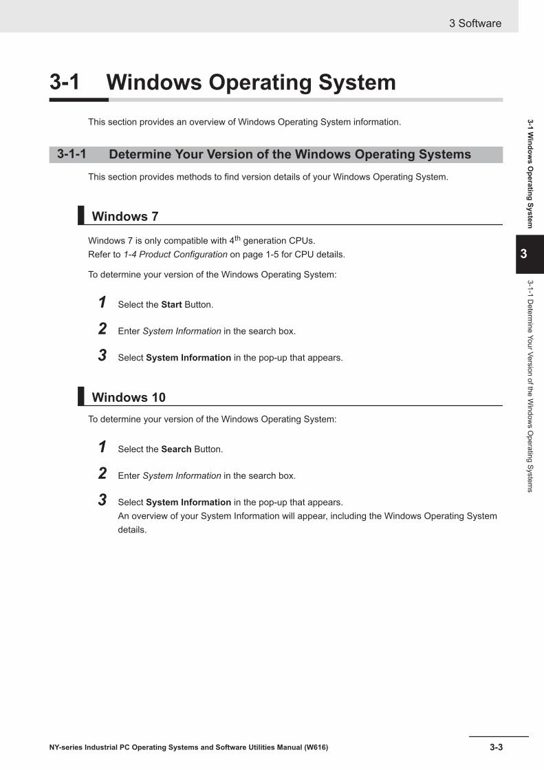
3-1 Windows Operating SystemThis section provides an overview of Windows Operating System information.
3-1-1 Determine Your Version of the Windows Operating SystemsThis section provides methods to find version details of your Windows Operating System.
Windows 7
Windows 7 is only compatible with 4th generation CPUs.Refer to 1-4 Product Configuration on page 1-5 for CPU details.
To determine your version of the Windows Operating System:
1 Select the Start Button.
2 Enter System Information in the search box.
3 Select System Information in the pop-up that appears.
Windows 10To determine your version of the Windows Operating System:
1 Select the Search Button.
2 Enter System Information in the search box.
3 Select System Information in the pop-up that appears.An overview of your System Information will appear, including the Windows Operating Systemdetails.
3 Software
3-3NY-series Industrial PC Operating Systems and Software Utilities Manual (W616)
3-1 Window
s Operating System
3
3-1-1 Determ
ine Your Version of the Window
s Operating System
s

3-2 Overview IPC Support Software forWindows
This section gives an overview of the software utilities available for all Industrial PC Platform productswith a Windows operating system.
Product Software utilityIndustrial Monitor Industrial Monitor Utility
Industrial Monitor Brightness Utility *1
Industrial PC Tray Utility *1*2*3
Industrial Box PC Industrial PC Support UtilityIndustrial PC Tray Utility *1*2*3
Rescue Disk CreatorIndustrial Panel PC Industrial Monitor Utility
Industrial Monitor Brightness Utility *1
Industrial PC Support UtilityIndustrial PC Tray Utility *1*2*3
Rescue Disk Creator*1. Included in the Industrial Monitor Utility installer*2. Included in the Industrial PC Support Utility installer*3. Together with the Industrial PC Tray Utility also Microsoft .NET Framework 4.6 is installed.
Select and download the required utilities from the OMRON website.
Additional Information
An internet connection is required to install support software.
3 Software
3-4 NY-series Industrial PC Operating Systems and Software Utilities Manual (W616)
3-3 Industrial PC Support UtilityThis section provides an overview of the Industrial PC Support Utility.
3 Software
3-5NY-series Industrial PC Operating Systems and Software Utilities Manual (W616)
3-3 Industrial PC Support U
tility
3
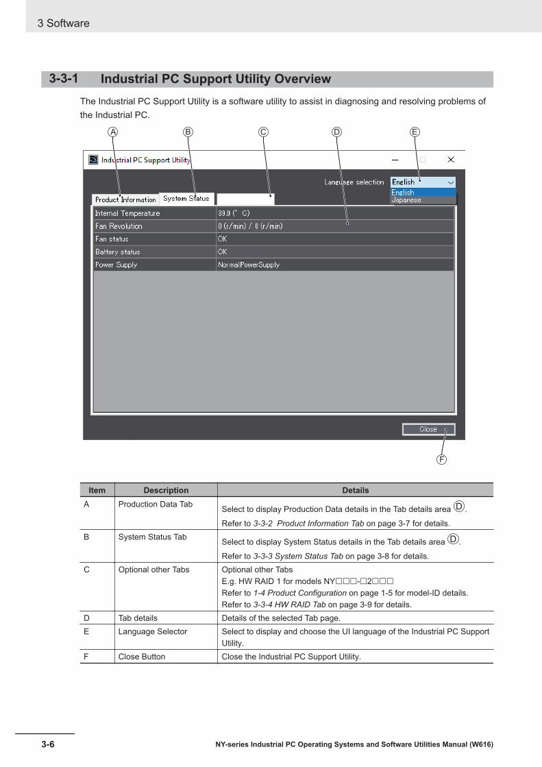
3-3-1 Industrial PC Support Utility OverviewThe Industrial PC Support Utility is a software utility to assist in diagnosing and resolving problems ofthe Industrial PC.
EDBA
F
C
Item Description DetailsA Production Data Tab Select to display Production Data details in the Tab details area C D .
Refer to 3-3-2 Product Information Tab on page 3-7 for details.B System Status Tab Select to display System Status details in the Tab details area C D .
Refer to 3-3-3 System Status Tab on page 3-8 for details.C Optional other Tabs Optional other Tabs
E.g. HW RAID 1 for models NY£££-£2£££Refer to 1-4 Product Configuration on page 1-5 for model-ID details.Refer to 3-3-4 HW RAID Tab on page 3-9 for details.
D Tab details Details of the selected Tab page.E Language Selector Select to display and choose the UI language of the Industrial PC Support
Utility.F Close Button Close the Industrial PC Support Utility.
3 Software
3-6 NY-series Industrial PC Operating Systems and Software Utilities Manual (W616)

3-3-2 Product Information TabThe Production Data tab displays generic Industrial PC information. These are e.g. Model name, Lotnumber, Serial number, Hardware version, BIOS version, BMC version, and software versions (Indus-trial PC Support Utility and Industrial PC System API).
• Model Name is the configuration code of this model.Refer to 1-4 Product Configuration on page 1-5 for details.
• BMC Version is the firmware version of the Board Management Controller.
3 Software
3-7NY-series Industrial PC Operating Systems and Software Utilities Manual (W616)
3-3 Industrial PC Support U
tility
3
3-3-2 Product Information Tab

3-3-3 System Status TabThe System Status tab displays actual states and diagnostic information like internal temperature, fanrevolution, battery and power supply status.A status that requires attention is indicated with a red bar.
Item DescriptionInternal Temperature The average CPU temperature.
Fan Revolution *1 The actual rotation speed for each fan in revolutions per minute (r/min).• First number = rotation speed of fan located closest to Power button.• Second number = rotation speed of fan located closest to battery.
Fan Status *2 The target speed for the fans is dynamically set based on the CPU temperature. Thetarget speed is compared with the actual fan speed.• OK indicates both fans are running on the target speed.• Low revolution speed indicates one or both fans do not reach the target speed.
Clean the fans and replace the Fan Unit if the problem persists.Battery Status The battery status.
• OK indicates the battery is full.• Low indicates the battery voltage is low. Replace the battery.
Power Supply The power supply status is determined by the UPS and reported to the IPC via the I/Oconnector.• NormalPowerSupply indicates the IPC is powered by the 24V power supply.• UPS Power Supply indicates that there is no power from the 24V power supply
and the IPC runs on battery power from the UPS.*1. The Fan Revolution will always show 0 (r/min) / 0 (r/min) for fanless models
Refer to 1-4 Product Configuration on page 1-5 for fan details.*2. The Fan Status will always show OK for fanless models
3 Software
3-8 NY-series Industrial PC Operating Systems and Software Utilities Manual (W616)

3-3-4 HW RAID TabHW RAID 1 is only available for models NY£££-£2£££Refer to 1-4 Product Configuration on page 1-5 for model-ID details.
The HW RAID tab displays the actual RAID state.
Item DescriptionFirmware The firmware version of the RAID controllerRAID Level The RAID LevelCapacity The available capacity of the RAID disksStatus State of the RAID disks
• NormalRAID is functional
• Rebuilding (...%)Creating RAID is in progress
• Degraded / BrokenError situation because RAID is not functional
The Details button displays storage device details and logging details.Refer to HW RAID Details on page 3-10 for details.
3 Software
3-9NY-series Industrial PC Operating Systems and Software Utilities Manual (W616)
3-3 Industrial PC Support U
tility
3
3-3-4 HW
RAID
Tab

HW RAID DetailsThe actual RAID state, displayed in the Industrial PC Tray Utility.
The status and details of each disk are displayed, including disk model name, serial number and ca-pacity. The status is None if there is no disk present. The status is - - - if detailed information can notbe retrieved.
RAID logging displays all RAID events.Possible RAID events:
Item DescriptionRAID is in normal The RAID state is normalRAID is in rebuilding The RAID state is busy rebuildingRAID is in degraded The RAID state is in the error situation degraded *1
RAID is in broken The RAID state is in the error situation broken *1
RAID has been rebuilt succesfully The RAID rebuilding completed with good resultsRAID rebuild process fails The RAID rebuilding did not complete with good resultsDisk […] is inserted Disk […] is detectedDisk […] is removed Disk […] is removedDisk […] is not found Disk […] is not foundDisk […] is RAID disk Disk […] type is detected as type RAIDDisk […] type is non-RAID Disk […] is not of type RAIDDisk […] type changed to non-RAID Disk […] type RAID changed to type non-RAIDDisk […] error Disk […] generates an error
*1. Refer to 7-2-9 Correct a RAID Array on page 7-37 for repair details.
3 Software
3-10 NY-series Industrial PC Operating Systems and Software Utilities Manual (W616)

3-3-5 CompatibilityCompatibility with Operating SystemsThis software utility can be used on an IPC with Windows 7 or higher.
Compatibility with related software utilitiesThe Industrial PC Tray Utility, the Industrial PC Support Utility and the Industrial Monitor Utility are re-lated. When during startup the error Could not load plugin: *\OMRON\*\Utility\*.dll appears softwareutilities are not compatible. Download and install the latest version of these software utilities.
3-3-6 InstallationThe Industrial PC Support Utility is pre-installed on the Industrial PC if it comes with a Windows oper-ating system installed.Download the Industrial PC Support Utility from the OMRON website if reinstallation is required.
Additional Information
A new installation on a Windows 10 PC will require the installation of the .net Framework.The .net Framework software can be downloaded from a Microsoft website.
3-3-7 StartupThe Industrial PC Support Utility can be started from:• Windows Start Menu
Select OMRON and then Industrial PC Support Utility.• Industrial PC Tray Utility• Windows desktop shortcut
3 Software
3-11NY-series Industrial PC Operating Systems and Software Utilities Manual (W616)
3-3 Industrial PC Support U
tility
3
3-3-5 Com
patibility

3-3-8 MessagesThe Industrial PC Support Utility can use the Industrial PC Tray Utility to display following messages:
Messagetype Message Description
Warning A normal shutdown was not performed. (Pow-erloss)
Power loss
Warning A normal shutdown was not performed.(Watchdog)
Watchdog was active
Warning A normal shutdown was not performed.(Forced)
A shutdown was forced
Warning A normal shutdown was not performed. (Cata-strophicTemperature)
Over temperature
3-3-9 LoggingThere is logging in the Windows event log of the following utilities:• Industrial Monitor Utility
In the Windows Event Viewer filter for event source IndMonService.• Industrial Monitor Brightness Utility
In the Windows Event Viewer filter for event source IndMonService.• Industrial PC Support Utility
In the Windows Event Viewer filter for event source IPCServiceHost or OMRON Industrial PCSupport Utility.
Additional Information
Refer to 7-2-4 Windows Event Viewer on page 7-29 for the logged messages.
3 Software
3-12 NY-series Industrial PC Operating Systems and Software Utilities Manual (W616)
3-4 Industrial Monitor UtilityThis section provides an overview of the Industrial Monitor Utility.
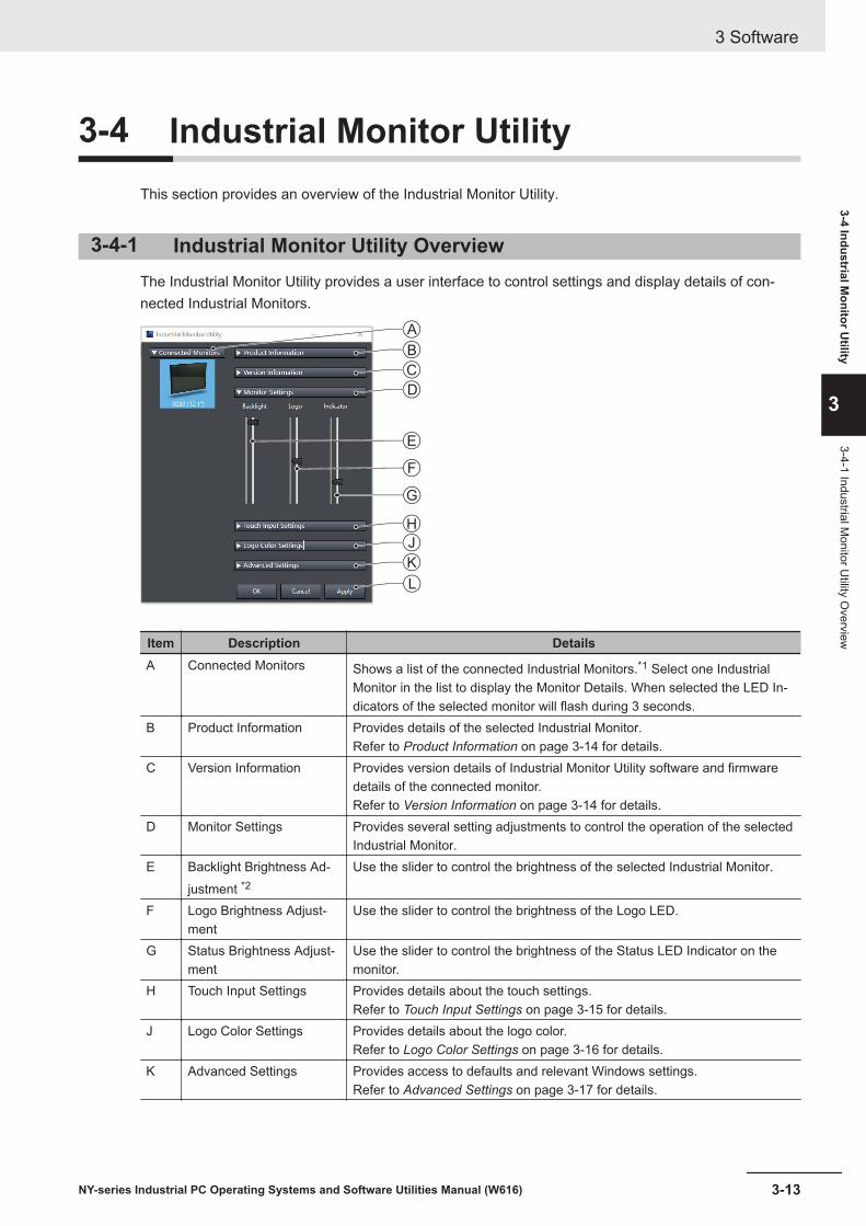
3-4-1 Industrial Monitor Utility OverviewThe Industrial Monitor Utility provides a user interface to control settings and display details of con-nected Industrial Monitors.
A
E
F
G
J
K
H
B
C
D
L
Item Description DetailsA Connected Monitors Shows a list of the connected Industrial Monitors.*1 Select one Industrial
Monitor in the list to display the Monitor Details. When selected the LED In-dicators of the selected monitor will flash during 3 seconds.
B Product Information Provides details of the selected Industrial Monitor.Refer to Product Information on page 3-14 for details.
C Version Information Provides version details of Industrial Monitor Utility software and firmwaredetails of the connected monitor.Refer to Version Information on page 3-14 for details.
D Monitor Settings Provides several setting adjustments to control the operation of the selectedIndustrial Monitor.
E Backlight Brightness Ad-justment *2
Use the slider to control the brightness of the selected Industrial Monitor.
F Logo Brightness Adjust-ment
Use the slider to control the brightness of the Logo LED.
G Status Brightness Adjust-ment
Use the slider to control the brightness of the Status LED Indicator on themonitor.
H Touch Input Settings Provides details about the touch settings.Refer to Touch Input Settings on page 3-15 for details.
J Logo Color Settings Provides details about the logo color.Refer to Logo Color Settings on page 3-16 for details.
K Advanced Settings Provides access to defaults and relevant Windows settings.Refer to Advanced Settings on page 3-17 for details.
3 Software
3-13NY-series Industrial PC Operating Systems and Software Utilities Manual (W616)
3-4 Industrial Monitor U
tility
3
3-4-1 Industrial Monitor U
tility Overview

Item Description DetailsL Standard windows but-
tons• OK button. Applies changes and closes the window• Cancel button. Exits the utility• Apply button. Applies the changes,
*1. The Industrial Monitor Utility scans the connected USB devices and shows a list of connected monitors. If anIndustrial Monitor is not connected with the USB cable, it will not be found.
*2. With a very low backlight brightness setting (15%-0%) the displayed information might not be visible in an envi-ronment with high ambient light conditions. This prevents brightness adjustments with the Industrial Monitor Utili-ty.
Additional Information
To adjust the backlight brightness when the brightness setting is set too low:• Bring the IPC in a low ambient light environment• Lighten the display with a bright flashlight
Product InformationThe Product Information part supplies details of the selected connected monitor.
Version InformationThe Version Information part supplies version details of the software and of the selected monitor.Software details:• The version of the Industrial Monitor Utility• The version of the Industrial Monitor APIMonitor details:• The Hardware version of the monitor• The version of the Firmware Software installed on the monitor• The version of the Touch Firmware installed on the monitor
3 Software
3-14 NY-series Industrial PC Operating Systems and Software Utilities Manual (W616)

Touch Input SettingsThe Touch Input Settings display the actual settings.
• PointSet to Single the monitor accepts only one touch point.Set to Multiple allows more touch points simultaneously.
• Water DetectionWhen enabled then a message will appear to inform the user when water is detected.When disabled then no message will appear when water is detected.
• Mouse EmulationWhen mouse emulation is enabled the Point setting is disabled and Press and Hold is enabled.When mouse emulation is disabled the Point setting is enabled and the Press and Hold is disabled.
Additional Information
Do not activate mouse emulation when using multiple industrial monitors in combination withextended mode.
• Press and HoldWhen enabled then a right-click mouse action occurs when holding a touch.When disabled then holding the touch does not trigger the right-click mouse action.
3 Software
3-15NY-series Industrial PC Operating Systems and Software Utilities Manual (W616)
3-4 Industrial Monitor U
tility
3
3-4-1 Industrial Monitor U
tility Overview

Logo Color SettingsThe logo color settings allows you to control the color of the customized logos of the selected Industri-al Monitor.
BA
Item Description DetailsA Color circle selection The color overview displaying the selected color.
The RGB selection will be updated accordinglyB RGB selection Displays the RGB values of the selected color
The color circle will be updated accordingly
Move the indicator in the color circle or change the RGB values to change the logo color of the select-ed monitor.Activate the Powershell Script to change the logo color of all connected monitors.Refer to Powershell Script for Connected Monitors on page 3-16 for details.
Additional Information
The color of the standard OMRON logo can not be changed.Used with the standard OMRON logo the brightness of the logo will be influenced.
Powershell Script for Connected MonitorsThe powershell script SetLogoColor.ps1'' is a script to make it convenient to change the logo colorof all connected monitors.Any change of the logo color in the Industrial Monitor Utility will update the powershell script withthe newly selected color. This script is available at C:\Omron\PSScript\SetLogoColor.ps1.Run the powerscript to change the logo color of all connected monitors.
3 Software
3-16 NY-series Industrial PC Operating Systems and Software Utilities Manual (W616)

Advanced SettingsAdvanced settings gives access to the factory settings and shortcuts to relevant Window settings.
• Restore Factory Defaults buttonResets all settings of the Industrial Monitor to the factory defaults.
• Tablet PC SettingsOpens the ‘Tablet PC Settings’-dialog of Windows.
• Pen and TouchOpens the ‘Pen and Touch’-dialog of Windows.
3 Software
3-17NY-series Industrial PC Operating Systems and Software Utilities Manual (W616)
3-4 Industrial Monitor U
tility
3
3-4-1 Industrial Monitor U
tility Overview

3-4-2 CompatibilityThis monitor utility can be used on any PC that is connected to an OMRON Industrial Monitor.Compatibility with Operating SystemsThis software utility can be used on an IPC with Windows 7 or higher.
Compatibility with related software utilitiesThe Industrial PC Tray Utility, the Industrial PC Support Utility and the Industrial Monitor Utility are re-lated. When during startup the error Could not load plugin: *\OMRON\*\Utility\*.dll appears softwareutilities are not compatible. Download and install the latest version of these software utilities.
Additional Information
The Industrial Monitor Utility does not support 3rd party monitors.
3-4-3 InstallationThe Industrial Monitor Utility is pre-installed on the Industrial PC if it comes with a Windows operatingsystem installed.Download the Industrial Monitor Utility from the OMRON website for reinstallation or for installation onanother Industrial PC.The Industrial Monitor Utility is installed onto Windows, and can be accessed via the Windows startmenu and the Industrial PC Tray Utility. Installing the Industrial Monitor Utility will also install the Indus-trial PC Tray Utility.
Precautions for Correct Use
When you use the Industrial Monitor Utility or Industrial Monitor Brightness Utility to adjust theIndustrial Monitors, connect them to the Industrial PC with a USB cable in advance.
Additional Information
Refer to 3-7 Industrial PC Tray Utility on page 3-31 for Industrial PC Tray Utility details.
3-4-4 StartupThe Industrial Monitor Utility can be started from:• Windows Start Menu.
Select Omron and then Industrial Monitor Utility.• Industrial PC Tray Utility
3 Software
3-18 NY-series Industrial PC Operating Systems and Software Utilities Manual (W616)

3-4-5 ConfigurationThe Industrial Monitor Utility can be configured with following options:
Configuration item DescriptionLanguage Follows the Windows language configuration when that language is supported for the
Industrial Monitor Utility. The default language English (EN-US) will be used if the lan-guage configured in Windows is not supported.
Monitor identification If enabled, the Status LED indicator on the selected Industrial Monitor will flash for 3seconds.To enable:1. Open the Windows registry key HKEY_LOCAL_MACHINE\SOFTWARE
\Wow6432Node\Omron\IPC\MonitorConfiguration2. Set the registry value Indicate to value True.
3-4-6 MessagesThe Industrial Monitor Utility can use the Industrial PC Tray Utility to display following messages:
Messagetype Message Description
Info Connected A new monitor connected• USB cable connected• Monitor powered ON
Warning Not Connected Monitor disconnected• USB cable disconnected• Monitor powered OFF
Warning Video Disconnected DVI cable disconnected or NY Monitor Linkcable disconnected
Warning Serial number: £Water detected on a monitorTouch may be rejectedCheck all attached monitors for water
Water is detected on monitor £
Warning No Signal DVI cable connected but no signal detected
3-4-7 LoggingThere is logging in the Windows event log of the following utilities:• Industrial Monitor Utility
In the Windows Event Viewer filter for event source IndMonService.• Industrial Monitor Brightness Utility
In the Windows Event Viewer filter for event source IndMonService.• Industrial PC Support Utility
In the Windows Event Viewer filter for event source IPCServiceHost or OMRON Industrial PCSupport Utility.
Additional Information
Refer to 7-2-4 Windows Event Viewer on page 7-29 for the logged messages.
3 Software
3-19NY-series Industrial PC Operating Systems and Software Utilities Manual (W616)
3-4 Industrial Monitor U
tility
3
3-4-5 Configuration
3-5 Industrial Monitor Brightness UtilityThis section provides an overview of the Industrial Monitor Brightness Utility.
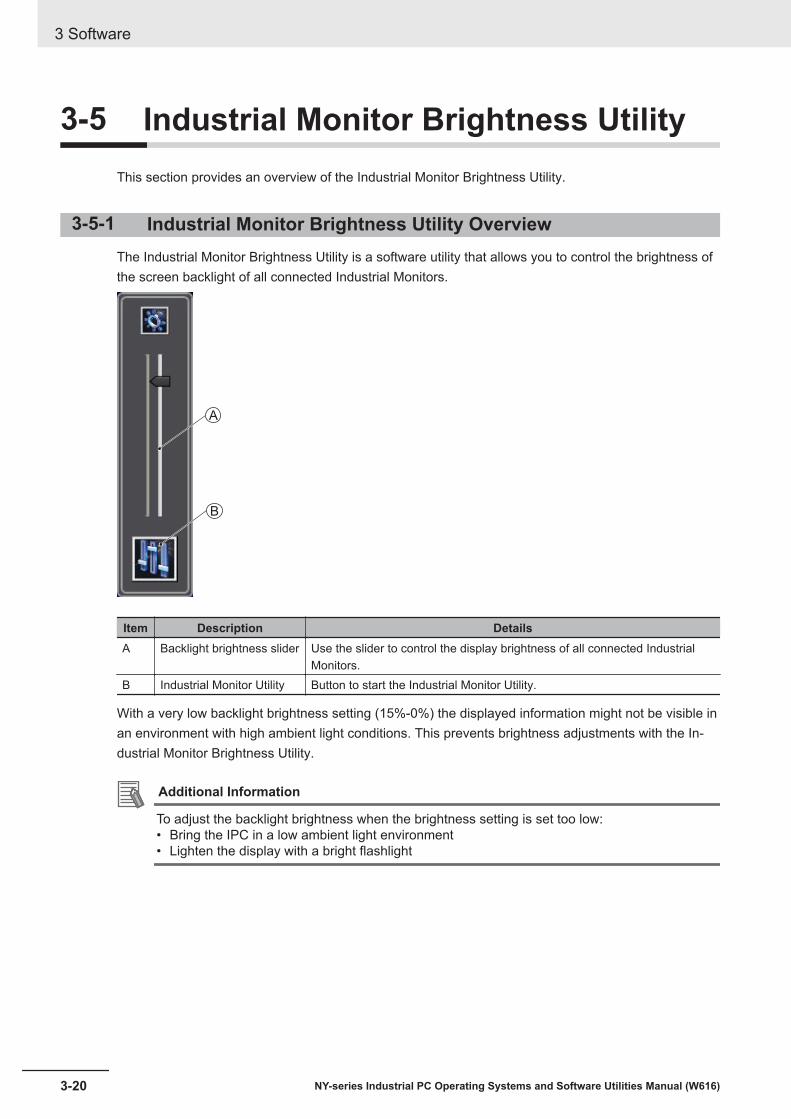
3-5-1 Industrial Monitor Brightness Utility OverviewThe Industrial Monitor Brightness Utility is a software utility that allows you to control the brightness ofthe screen backlight of all connected Industrial Monitors.
A
B
Item Description DetailsA Backlight brightness slider Use the slider to control the display brightness of all connected Industrial
Monitors.B Industrial Monitor Utility Button to start the Industrial Monitor Utility.
With a very low backlight brightness setting (15%-0%) the displayed information might not be visible inan environment with high ambient light conditions. This prevents brightness adjustments with the In-dustrial Monitor Brightness Utility.
Additional Information
To adjust the backlight brightness when the brightness setting is set too low:• Bring the IPC in a low ambient light environment• Lighten the display with a bright flashlight
3 Software
3-20 NY-series Industrial PC Operating Systems and Software Utilities Manual (W616)

3-5-2 CompatibilityThis monitor utility can be used on any PC that is connected to an OMRON Industrial Monitor.Compatibility with Operating SystemsThis software utility can be used on an IPC with Windows 7 or higher.
Compatibility with related software utilitiesThe Industrial PC Tray Utility, the Industrial PC Support Utility and the Industrial Monitor Utility are re-lated. When during startup the error Could not load plugin: *\OMRON\*\Utility\*.dll appears softwareutilities are not compatible. Download and install the latest version of these software utilities.
Additional Information
The Industrial Monitor Utility does not support 3rd party monitors.
3-5-3 InstallationThe Industrial Monitor Brightness Utility is pre-installed on the Industrial PC if it comes with a Windowsoperating system installed.Installation of the Industrial Monitor Brightness Utility is part of the installation of the Industrial MonitorUtility.Download the Industrial Monitor Utility from the OMRON website for reinstallation or for installation onanother PC with a compatible operating system.The Industrial Monitor Brightness Utility is installed onto Windows, and can be accessed via the Win-dows start menu and the Industrial PC Tray Utility. Installing the Industrial Monitor Utility will also in-stall the Industrial PC Tray Utility.
Precautions for Correct Use
When you use the Industrial Monitor Utility or Industrial Monitor Brightness Utility to adjust theIndustrial Monitors, connect them to the Industrial PC with a USB cable in advance.
Additional Information
Refer to 3-7 Industrial PC Tray Utility on page 3-31 for Industrial PC Tray Utility details.
3-5-4 StartupStart the Industrial Monitor Brightness Utility from the Industrial PC Tray Utility or from the WindowsStart Menu (select Omron and then Industrial Monitor Brightness Utility ).
Additional Information
Refer to 3-7 Industrial PC Tray Utility on page 3-31 for Industrial PC Tray Utility details.
3-5-5 ConfigurationConfiguration is not required.This utility will detect and support all connected NY-series Industrial Monitors.
3 Software
3-21NY-series Industrial PC Operating Systems and Software Utilities Manual (W616)
3-5 Industrial Monitor B
rightness Utility
3
3-5-2 Com
patibility
3-5-6 LoggingThere is logging in the Windows event log of the following utilities:• Industrial Monitor Utility
In the Windows Event Viewer filter for event source IndMonService.• Industrial Monitor Brightness Utility
In the Windows Event Viewer filter for event source IndMonService.• Industrial PC Support Utility
In the Windows Event Viewer filter for event source IPCServiceHost or OMRON Industrial PCSupport Utility.
Additional Information
Refer to 7-2-4 Windows Event Viewer on page 7-29 for the logged messages.
3 Software
3-22 NY-series Industrial PC Operating Systems and Software Utilities Manual (W616)

3-6 Rescue Disk Creator and UtilityThis section provides an overview of the Rescue Disk software.
The Rescue Disk Creator is software that creates the Rescue Disk Utility on a USB storage device.
The Rescue Disk Utility is a tool used to back up and recover data of Windows and Real-Time OS(Controller function) of an Industrial PC. The Rescue Disk Utility creates image files of the storage de-vice of an Industrial PC, and backs them up in a USB connected storage device.
3-6-1 OverviewThe Rescue Disk Creator (RDC) creates a Rescue Disk.A Rescue Disk is a disk with the Rescue Disk Utility; this is the software that performs the systembackup and system restore procedures.
D
F
G
H
A
B
C
E
3 Software
3-23NY-series Industrial PC Operating Systems and Software Utilities Manual (W616)
3-6 Rescue D
isk Creator and U
tility
3
3-6-1 Overview

Version Information
Specifications and functionality can change between different versions of the Rescue Disk Cre-ator Utility. This can result in changes in the content of the Utility window.Major change in version (1.2.3.0) is the addition of Model selection B and Operating System
selection C .
Item Description DetailsA Explanation area Information about the utility and the backup.
In the right bottom corner messages are displayed when applicable.B Model selection The RDC on an OMRON IPC displays the found model name with-
out radio buttons.The RDC on other PCs displays the radio buttons for a selection bythe user.
C Operating System selection The RDC on an OMRON IPC displays the found operating systemwithout radio buttons.The RDC on other PCs displays the radio buttons for a selection bythe user.
D Target disk selection Selection of the disk that will become the Rescue Disk.E Show All Disks Check the box to display not only the removable storage devices
but also the non-removable (internal) storage devices and USBFlash Drives and other USB storage devices.
F Create Rescue Disk Button Start the Rescue Disk creation.G Creation progress bar Display the progress of the Rescue Disk creation.H Close Button Close the Rescue Disk Creator.
Additional Information
• Refer to Create a System Backup with the Rescue Disk on page 7-5 for system backupdetails.
• Refer to Restore a System Backup with the Rescue Disk on page 7-21 for system restoredetails.
3-6-2 CompatibilityCompatibility with Operating SystemsThis Rescue Disk software can be used on the IPC but also on any other PC with one of the followingoperating systems:• Windows 10• Windows 7Compatibility related to versions of Rescue Disk softwareRefer to Control Panel - Programs and Features for the version of Rescue Disk Creator.
3 Software
3-24 NY-series Industrial PC Operating Systems and Software Utilities Manual (W616)

Precautions for Correct Use
Rescue Disk Creator version 1.0.830The data that was backed up with the Rescue Disk Utility installed with Rescue Disk Creatorversion 1.0.830 can be used only to recover the Industrial PC from which you backed up thedata. You cannot use the data to recover other Industrial PCs.
Rescue Disk Creator version 1.1.1257 or higherThe data that was backed up with the Rescue Disk Utility installed with Rescue Disk Creatorversion 1.1.1257 or higher can be recovered for an Industrial PC with the same unit version andan identical model-ID. Refer to 1-4 Product Configuration on page 1-5 for details.
Version Information
Rescue Disk Creator version 1.1.2004 or lowerSupports Windows 7.
Rescue Disk Creator version 1.2.3.0178 or higherSupports Windows 7 and Windows 10.
3 Software
3-25NY-series Industrial PC Operating Systems and Software Utilities Manual (W616)
3-6 Rescue D
isk Creator and U
tility
3
3-6-2 Com
patibility
3-6-3 InstallationThe Rescue Disk Creator is preinstalled on the Industrial PC if it comes with a Windows operating sys-tem installed.
Use the following procedure to reinstall the Rescue Disk Creator:
1 Use Windows Explorer to open the Rescue Disk folder (C:\Program Files (x86)\OMRON\Indus-trial PC\Rescue Disk).
2 Activate the installer file setup.exe.A progress bar will visualize the extraction process and then a language selection windowopens.
3 Select your language and then select OK.The installer window opens.
4 Follow the installer steps to complete the Rescue Disk Creator installation.
The Rescue Disk Creator is installed and available in the OMRON folder in the Windows Start Menu.
3 Software
3-26 NY-series Industrial PC Operating Systems and Software Utilities Manual (W616)
3-6-4 StartupTo manually start the Rescue Disk Creator:
1 Locate the Rescue Disk Creator using the Windows Start menu or the Windows search box.
2 Use the option Run as administrator to start the Rescue Disk Creator.
Additional Information
The procedure to use Run as administrator is:• For Windows 10 using the Start menu:
Right-click the Rescue Disk Creator, select More and then Run as administrator.• For Windows 10 using Search:
Right-click the Rescue Disk Creator in the search results and select Run as administrator.• For Windows 7 using the Start menu or Search:
Right-click the Rescue Disk Creator and select Run as administrator.
3 Follow the on-screen instructions to complete the rescue disk.Use a USB storage device with a capacity of at least the Windows partition size + 16 GB. Therecommended minimum read/write speed is 190 MB/s.
Additional Information
Depending on the situation additional actions might be required:• When the RDC is active on an IPC then the applicable Models and Operating System'are
automatically displayed.When this information can not be retrieved the message The IPC model is unknown,please use the latest Rescue Disk Creator downloaded from the OMRON Website. ap-pears. In that situation download and install the latest RDC from the OMRON website and re-start this procedure.
• When the RDC is active on an a PC then manually select the type of Models and OperatingSystem'applicable to your system.
A Rescue Disk is created by the Rescue Disk Creator.
3-6-5 MessagesThe Rescue Disk Creator creates a rescue disk in two steps:
1. Format the target disk
2. Copy the rescue disk image to the target disk
Messages can inform the user of an error when applicable.Refer to Error Messages Creating the Rescue Disk on page 3-28 for details.
Use the rescue disk to create a backup or restore your disk.Messages can inform the user of a backup or restore error when applicable.Refer to Messages Using the Rescue Disk on page 3-29 for details.
3 Software
3-27NY-series Industrial PC Operating Systems and Software Utilities Manual (W616)
3-6 Rescue D
isk Creator and U
tility
3
3-6-4 Startup

Error Messages Creating the Rescue DiskThe Rescue Disk Creator can display the following error messages:
Message DescriptionCreation progress: Failed to format the disk. Reason:• Access denied• Call canceled• Call cancellation request too late• Cluster size is beyond 32 bits• Cluster size is too large• Cluster size is too small• Incompatible media in drive• Invalid volume label• Input/Output (I/O) error• No media in drive• Unable to quick format• Unknown error• Unsupported file system• Volume lock failed• Volume is not mounted• Volume is too large• Volume is too small• Volume write protected
The mentioned reason prevented formatting of theconnected storage device.Ensure the connected storage device:• Is not write protected or read-only• Has a cluster size too small or more than the maxi-
mum 32 bits• Has a valid volume label• Has sufficient storage capacity to store the rescue
disk utility and a full system backup
Creation progress: Failed to copy image to rescuedisk.Reason:• Unable to revoke access to the disk• Unable to revoke access to the drive• Disk write failed• Unable to dismount the drive• Invalid drive• Unable to obtain exclusive access to the drive• The disk could not be accessed• The drive could not be accessed• Unable to revoke exclusive access to the drive
The mentioned reason prevented copying the image tothe connected storage device.Ensure the connected storage device:• Is not used by other programs• Is not write protected or read-only
To solve an error:
1. Check that the correct target disk was selected.
2. Check that the target disk has sufficient storage capacity to store the rescue disk utility and a fullsystem backup
3. If the storage device is removable, check that it is inserted properly and is of the correct type.
4. Check whether the storage device is write protected. SD Memory Cards often have a small me-chanical write protection switch on them.
5. Check that the user has the necessary access rights for the target disk.
6. Check that the Rescue Disk Creator is running "As Administrator".
7. Check that no other applications are using the target disk.
8. Retry the operation with the same target disk.
9. Retry the operation with a different target disk.
3 Software
3-28 NY-series Industrial PC Operating Systems and Software Utilities Manual (W616)
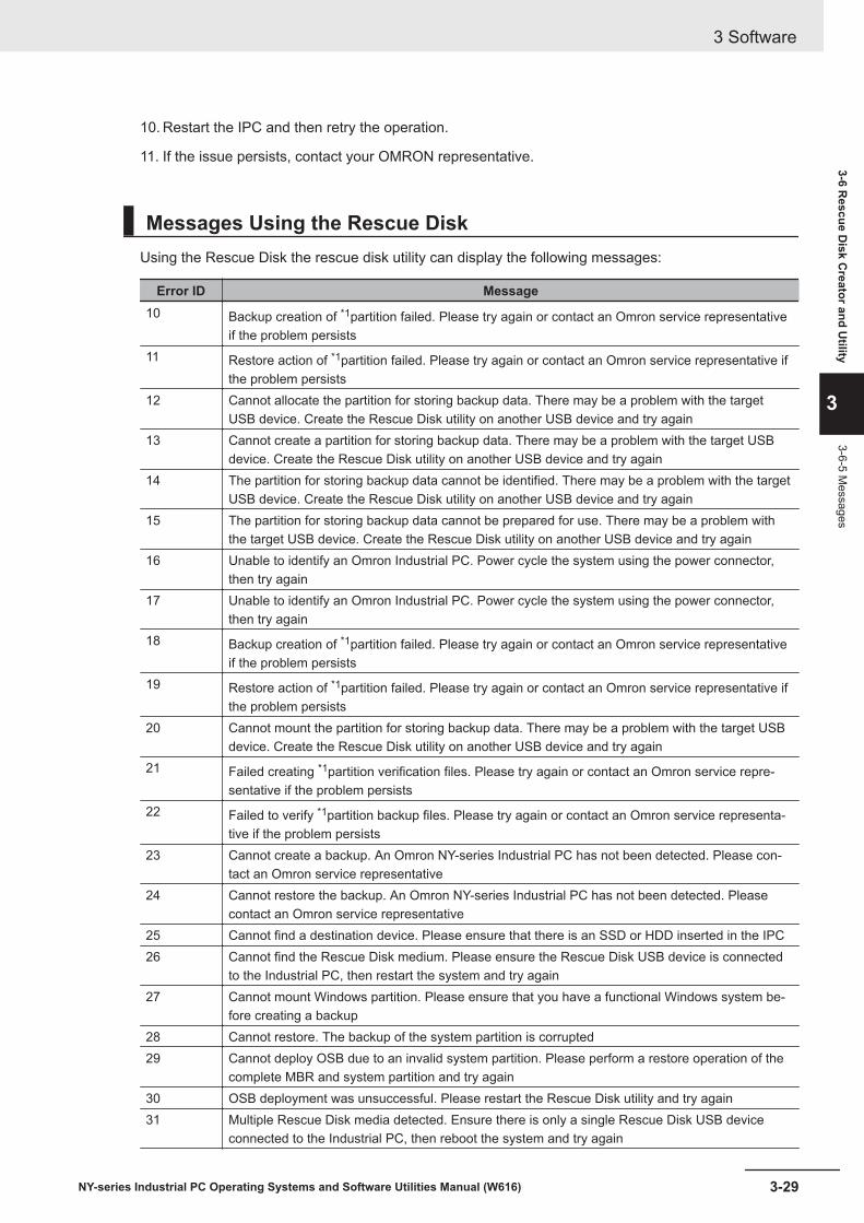
10. Restart the IPC and then retry the operation.
11. If the issue persists, contact your OMRON representative.
Messages Using the Rescue DiskUsing the Rescue Disk the rescue disk utility can display the following messages:
Error ID Message10 Backup creation of *1partition failed. Please try again or contact an Omron service representative
if the problem persists11 Restore action of *1partition failed. Please try again or contact an Omron service representative if
the problem persists12 Cannot allocate the partition for storing backup data. There may be a problem with the target
USB device. Create the Rescue Disk utility on another USB device and try again13 Cannot create a partition for storing backup data. There may be a problem with the target USB
device. Create the Rescue Disk utility on another USB device and try again14 The partition for storing backup data cannot be identified. There may be a problem with the target
USB device. Create the Rescue Disk utility on another USB device and try again15 The partition for storing backup data cannot be prepared for use. There may be a problem with
the target USB device. Create the Rescue Disk utility on another USB device and try again16 Unable to identify an Omron Industrial PC. Power cycle the system using the power connector,
then try again17 Unable to identify an Omron Industrial PC. Power cycle the system using the power connector,
then try again18 Backup creation of *1partition failed. Please try again or contact an Omron service representative
if the problem persists19 Restore action of *1partition failed. Please try again or contact an Omron service representative if
the problem persists20 Cannot mount the partition for storing backup data. There may be a problem with the target USB
device. Create the Rescue Disk utility on another USB device and try again21 Failed creating *1partition verification files. Please try again or contact an Omron service repre-
sentative if the problem persists22 Failed to verify *1partition backup files. Please try again or contact an Omron service representa-
tive if the problem persists23 Cannot create a backup. An Omron NY-series Industrial PC has not been detected. Please con-
tact an Omron service representative24 Cannot restore the backup. An Omron NY-series Industrial PC has not been detected. Please
contact an Omron service representative25 Cannot find a destination device. Please ensure that there is an SSD or HDD inserted in the IPC26 Cannot find the Rescue Disk medium. Please ensure the Rescue Disk USB device is connected
to the Industrial PC, then restart the system and try again27 Cannot mount Windows partition. Please ensure that you have a functional Windows system be-
fore creating a backup28 Cannot restore. The backup of the system partition is corrupted29 Cannot deploy OSB due to an invalid system partition. Please perform a restore operation of the
complete MBR and system partition and try again30 OSB deployment was unsuccessful. Please restart the Rescue Disk utility and try again31 Multiple Rescue Disk media detected. Ensure there is only a single Rescue Disk USB device
connected to the Industrial PC, then reboot the system and try again
3 Software
3-29NY-series Industrial PC Operating Systems and Software Utilities Manual (W616)
3-6 Rescue D
isk Creator and U
tility
3
3-6-5 Messages

Error ID Message32 Cannot create backup records data due to missing OSB data33 Cannot create backup records due to missing NX data34 Cannot create backup records due to a missing system partition35 Cannot find a source device. Please ensure that there is an SSD or HDD inserted in the IPC36 Multiple disks detected with the same partition layout. Please ensure there is only one SSD or
HDD inserted in the IPC to restore the backup37 Multiple source devices detected. To backup the correct disk, please ensure that there is only one
SSD or HDD inserted in the IPC38 Unable to create a partition in the AI database disk39 AI database disk creation (partitioning and formatting) failed40 Unable to identify a suitable disk to format as AI database disk. Please ensure there is one SSD
or HDD that has no Windows OS41 Multiple disks detected suitable to format as AI database disk. Please ensure there is only one
SSD or HDD that has no Windows OS42 Unable to identify any Windows disk. Please ensure that a Windows disk is inserted in the IPC43 Multiple Windows disks detected. Please ensure that there is only one Windows disk inserted in
the IPC44 Can not find the Master Boot Record.45 Self diagnostics tool could not be found.46 Self diagnostics tool could not detect any disks.47 This Rescue Disk Utility version is not compatible with this Industrial PC.
Please make a new Rescue Disk Utility using the Rescue Disk Creator on your IPC.Refer to 3-6-2 Compatibility on page 3-24 for details.
48 This Rescue Disk Utility version is not compatible with this Industrial PC.Please make a new Rescue Disk Utility using the Rescue Disk Creator on your IPC.Refer to 3-6-2 Compatibility on page 3-24 for details.
*1. The partition name will be indicated. Examples are 'System partition' or 'Master Boot Record' .
3 Software
3-30 NY-series Industrial PC Operating Systems and Software Utilities Manual (W616)

3-7 Industrial PC Tray UtilityThis section provides an overview of the Industrial PC Tray Utility.
3-7-1 Industrial PC Tray Utility OverviewThe Industrial PC Tray Utility is a software utility that provides information about the current state ofthe Industrial PC, its related devices, and associated software.
When running, the Industrial PC Tray Utility is always present as a status icon A in the system tray
area B of Windows.
A B
Windows 10
3-7-2 FeaturesThe Industrial PC Tray Utility provides the following features:• Display the overall state of all installed OMRON software utilities in the icon in the system tray area.• Display a menu that can start all installed software utilities and show the state of each installed soft-
ware utility.• Display notification messages in popup windows that inform the user about the state of applications
or hardware. The Industrial PC Tray Utility displays the messages provided by installed software util-ities. Refer to the details of a specific software utility for the messages that can be displayed.
3 Software
3-31NY-series Industrial PC Operating Systems and Software Utilities Manual (W616)
3-7 Industrial PC Tray U
tility
3
3-7-1 Industrial PC Tray U
tility Overview
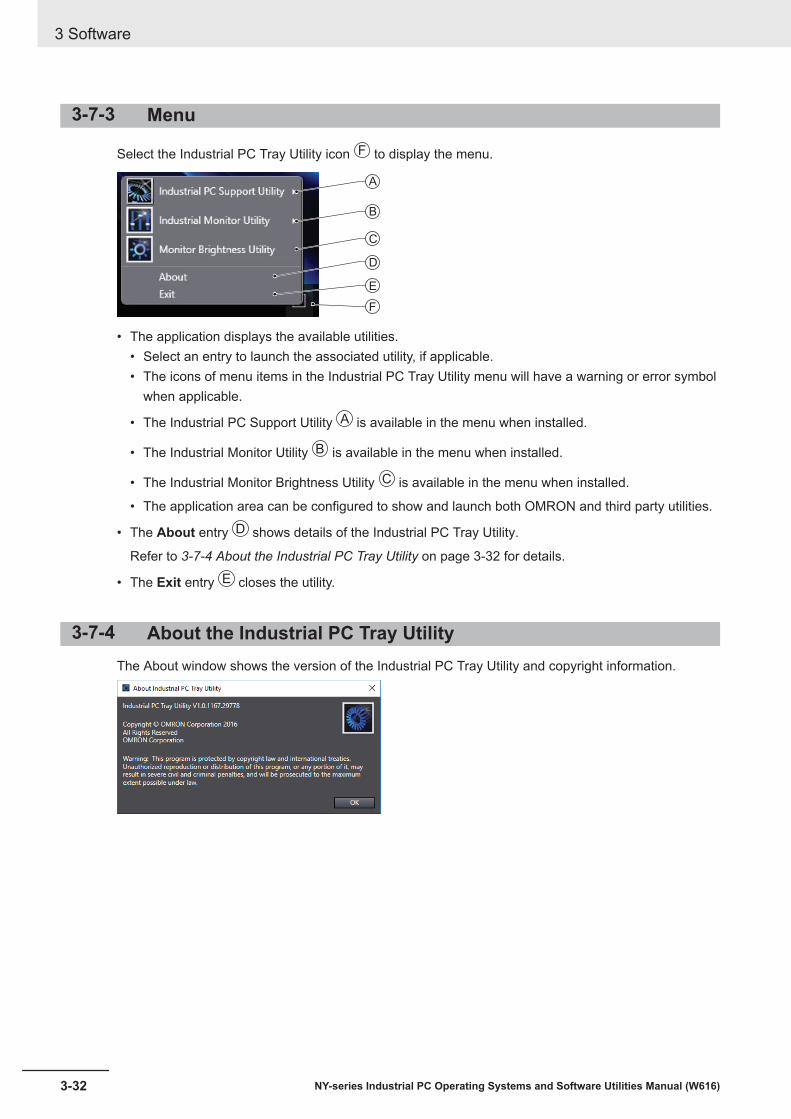
3-7-3 Menu
Select the Industrial PC Tray Utility icon F to display the menu.
B
C
E
F
D
A
• The application displays the available utilities.• Select an entry to launch the associated utility, if applicable.• The icons of menu items in the Industrial PC Tray Utility menu will have a warning or error symbol
when applicable.
• The Industrial PC Support Utility A is available in the menu when installed.
• The Industrial Monitor Utility B is available in the menu when installed.
• The Industrial Monitor Brightness Utility C is available in the menu when installed.
• The application area can be configured to show and launch both OMRON and third party utilities.
• The About entry C D shows details of the Industrial PC Tray Utility.
Refer to 3-7-4 About the Industrial PC Tray Utility on page 3-32 for details.
• The Exit entry E closes the utility.
3-7-4 About the Industrial PC Tray UtilityThe About window shows the version of the Industrial PC Tray Utility and copyright information.
3 Software
3-32 NY-series Industrial PC Operating Systems and Software Utilities Manual (W616)
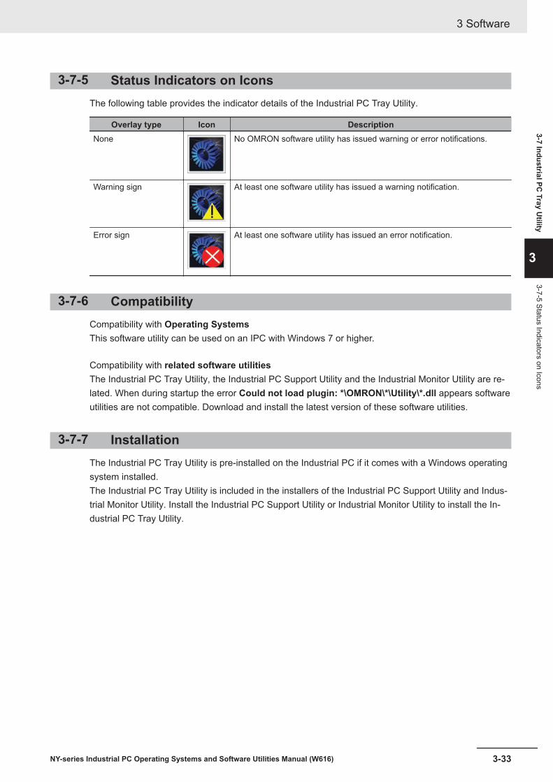
3-7-5 Status Indicators on IconsThe following table provides the indicator details of the Industrial PC Tray Utility.
Overlay type Icon DescriptionNone No OMRON software utility has issued warning or error notifications.
Warning sign At least one software utility has issued a warning notification.
Error sign At least one software utility has issued an error notification.
3-7-6 CompatibilityCompatibility with Operating SystemsThis software utility can be used on an IPC with Windows 7 or higher.
Compatibility with related software utilitiesThe Industrial PC Tray Utility, the Industrial PC Support Utility and the Industrial Monitor Utility are re-lated. When during startup the error Could not load plugin: *\OMRON\*\Utility\*.dll appears softwareutilities are not compatible. Download and install the latest version of these software utilities.
3-7-7 InstallationThe Industrial PC Tray Utility is pre-installed on the Industrial PC if it comes with a Windows operatingsystem installed.The Industrial PC Tray Utility is included in the installers of the Industrial PC Support Utility and Indus-trial Monitor Utility. Install the Industrial PC Support Utility or Industrial Monitor Utility to install the In-dustrial PC Tray Utility.
3 Software
3-33NY-series Industrial PC Operating Systems and Software Utilities Manual (W616)
3-7 Industrial PC Tray U
tility
3
3-7-5 Status Indicators on Icons

3-7-8 StartupBy default the Industrial PC Tray Utility is configured to start automatically at Windows startup.
To manually start the Industrial PC Tray Utility:
1 Locate the Industrial PC Tray Utility using the Windows Start menu or the Windows searchbox.
2 Use the option Run as administrator to activate the Industrial PC Tray Utility.
Additional Information
The procedure to use Run as administrator is:• For Windows 10 using the Start menu:
Right-click the Industrial PC Tray Utility, select More and then Run as administrator.• For Windows 10 using Search:
Right-click the Industrial PC Tray Utility in the search results and select Run asadministrator.
• For Windows 7 using the Start menu or Search:Right-click the Industrial PC Tray Utility and select Run as administrator.
The Industrial PC Tray Utility started.
3 Software
3-34 NY-series Industrial PC Operating Systems and Software Utilities Manual (W616)
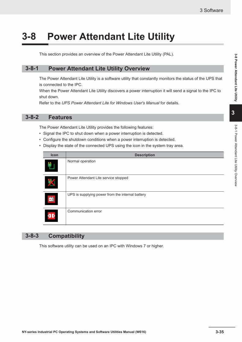
3-8 Power Attendant Lite UtilityThis section provides an overview of the Power Attendant Lite Utility (PAL).
3-8-1 Power Attendant Lite Utility OverviewThe Power Attendant Lite Utility is a software utility that constantly monitors the status of the UPS thatis connected to the IPC.When the Power Attendant Lite Utility discovers a power interruption it will send a signal to the IPC toshut down.Refer to the UPS Power Attendant Lite for Windows User's Manual for details.
3-8-2 FeaturesThe Power Attendant Lite Utility provides the following features:• Signal the IPC to shut down when a power interruption is detected.• Configure the shutdown conditions when a power interruption is detected.• Display the state of the connected UPS using the icon in the system tray area.
Icon DescriptionNormal operation
Power Attendant Lite service stopped
UPS is supplying power from the internal battery
Communication error
3-8-3 CompatibilityThis software utility can be used on an IPC with Windows 7 or higher.
3 Software
3-35NY-series Industrial PC Operating Systems and Software Utilities Manual (W616)
3-8 Power A
ttendant Lite Utility
3
3-8-1 Power Attendant Lite U
tility Overview

3-8-4 InstallationThe Power Attendant Lite Utility is not pre-installed on a IPC.The Power Attendant Lite Utility installer is included in the installers directory (D:\OMRON-NY\Instal-lers). Download the installer from the OMRON website if required.
To install the Power Attendant Lite Utility:
1 Ensure the revision number of the UPS is correct.Refer to the Hardware Manual for details.
2 Ensure the UPS is connected to the IPC with a USB cable.
3 Open the Power Attendant Lite Utility installer folder and activate the installer file setup.exe.
4 Follow the installer steps to complete the installation.The Power Attendant Lite Utility is installed.
3-8-5 ConfigurationConfigure the Power Attendant Lite Utility before using the IPC with a UPS connected using USB.
To configure the Power Attendant Lite Utility:
1 Activate the icon of the Power Attendant Lite Utility to start the software.
A UPS selection window will be displayed.
2 Select the connected UPS.A Login window will be displayed.
3 Login with ID Admin and password omron.The Top window with UPS status information will be displayed.
4 Configure the parameters for your specific situation.
3 Software
3-36 NY-series Industrial PC Operating Systems and Software Utilities Manual (W616)

Refer to UPS Power Attendant Lite for Windows User's Manual for details.
5 Select Detailed Setting / Other Settings / Communication Setting / UPS CommunicationPort to display the parameter COM search to UPS detection.
6 Set the parameter to Do not search for COM ports to prevent interference for the COM ports.
7 Select Submit to save the setting.
8 Select the close button in the right top corner to exit the Power Attendant Lite Utility software.
9 Select the restart behavior of the IPC with the BIOS Boot Menu parameter Power Loss Con-trol.Set this parameter to Turn On to restart automatically after a power down from the Power At-tendant Lite Utility.
10 Test the UPS shutdown behavior.
1) Start the IPC
2) Start applications
3) Create a power interruption
4) Monitor the shutdown sequence and confirm a correct shutdownWhen the shutdown sequence is not correct change parameters in the Power AttendantLite Utility software and test the UPS shutdown behavior again.
The Power Attendant Lite Utility is configured.The IPC will shut down properly in case of a power supply interruption and restart automatically whenthe power is restored.
3 Software
3-37NY-series Industrial PC Operating Systems and Software Utilities Manual (W616)
3-8 Power A
ttendant Lite Utility
3
3-8-5 Configuration

3-9 Software for DevelopersThis section provides information on the software that is available for developers.
3-9-1 Overview of IPC Developer Software for WindowsThis section gives an overview of the software available for developers for all Industrial PC Platformproducts with a Windows operating system.
Availability of the developer software:
Product Developer softwareIndustrial Monitor Industrial Monitor SDK
Industrial Monitor APIIndustrial Box PC Industrial PC System SDK
Industrial PC System APIIndustrial Panel PC Industrial Monitor SDK
Industrial Monitor APIIndustrial PC System SDKIndustrial PC System API
Select and download the SDK software from the OMRON website.
A short description of the developer software:
Type of API Description ReferenceIndustrial PC System API Gets information on the Industrial PC, such as
production information, temperature, and bat-tery status.
3-9-2 Industrial PC Sys-tem API on page 3-39
Industrial Monitor API Controls the hardware features and gets infor-mation from connected Industrial Monitors.
3-9-3 Industrial MonitorAPI on page 3-40
Development EnvironmentThe following development environment is required to create applications with the Industrial PC API.
Integrated Development EnvironmentMicrosoft Visual Studio 2010, 2012, or 2013
Programming LanguagesVisual C#
3 Software
3-38 NY-series Industrial PC Operating Systems and Software Utilities Manual (W616)

3-9-2 Industrial PC System APIThis section describes some of the Industrial PC System API functions.The Industrial PC System API allows programmers to create programs that can retrieve information orset an indicator status of the product.The API makes use of the included OMRON IPC System Service to manage the hardware.
FeaturesThe Industrial PC System API can:• Retrieve product information from the Industrial PC• Retrieve system flags• Retrieve maintenance information
• Configure and program the Watchdog*1
• Set the status of the Run LED Indicator and the ERR LED Indicator*1
*1 Only for Industrial PCs with a Windows operating system.
InstallationThe Industrial PC System API is part of the Industrial PC System SDK download.The Industrial PC System API is pre-installed on the Industrial Panel PC and the Industrial Box PC.
Install the Industrial PC System SDK to use the Industrial PC System API on development PCs.
To use the Industrial PC System API the API needs to be referenced in your development project.Use the Merge Module to include the Industrial PC System API in the installer for custom applications.
3 Software
3-39NY-series Industrial PC Operating Systems and Software Utilities Manual (W616)
3-9 Software for D
evelopers
3
3-9-2 Industrial PC System
API
3-9-3 Industrial Monitor APIThis section describes some of the Industrial Monitor API functions.The Industrial Monitor API allows programmers to create applications that can control the hardwarefeatures and retrieve information from connected Industrial Monitors.The main function of the Industrial Monitor API is to enable the brightness of the backlight and theLEDs of the monitor to be increased or decreased according to the working environment.The API makes use of the included OMRON Industrial Monitor Service to manage the hardware.
FeaturesFor all connected Industrial Monitors, the Industrial Monitor API can:• Retrieve product information from the Industrial Monitor or Industrial Panel PC display• Retrieve product status information• Set the brightness of the Status LED indicator• Set the brightness of the backlight• Set the brightness of the Logo LED• Set the touch points of the monitor• Store settings• Restore to factory defaultsThe API makes use of the included OMRON Industrial Monitor Service to manage all Industrial Moni-tors connected via USB.
InstallationThe Industrial Monitor API is part of the Industrial Monitor SDK download.The Industrial Monitor API is pre-installed on the Industrial Panel PC and Industrial Box PC.
Install the Industrial Monitor SDK to use the Industrial Monitor API on development PCs.
To use the Industrial Monitor API the API needs to be referenced in your development project.Use the Merge Module to include the Industrial Monitor API in the installer for custom applications.
3 Software
3-40 NY-series Industrial PC Operating Systems and Software Utilities Manual (W616)

4Specifications
This section provides specifications of the Industrial PC.
4-1 Software Specifications ................................................................................ 4-24-1-1 Compatible Operating Systems....................................................................... 4-24-1-2 Available Windows Operating Systems........................................................... 4-3
4-1NY-series Industrial PC Operating Systems and Software Utilities Manual (W616)
4

4-1 Software SpecificationsThis section provides the Software Specifications of the Industrial PC.
4-1-1 Compatible Operating SystemsThe operating system installed on the IPC must be:• compatible with the Advanced Configuration and Power Interface (ACPI) protocol• installed on the storage device in drive bay A
Compatible operating systems for the IPC are:
• Windows 7, only for 4th generation CPUs• Windows 10• Wind River Linux 7 (64bit)• Wind River VxWorks 7 (64bit)• Linux Ubuntu LTS 14.04 (64Bit)
Additional Information
Install applicable hardware drivers and support software to access all features of the IPC.• Refer to 5-1 Install Software on page 5-2 for details.• Refer to 5-2 Install Support Software on page 5-5 for details.
4 Specifications
4-2 NY-series Industrial PC Operating Systems and Software Utilities Manual (W616)

4-1-2 Available Windows Operating SystemsThe CPU type determines what Windows Operating Systems are available.The CPU type is part of the model-ID.Refer to 1-4 Product Configuration on page 1-5 for model-ID details.
Model-IDWindowsOperating
SystemEdition Remark
• NY£2A Windows 10 Windows 10IoT Enterprise 2019 LTSC -64 bit
The Long-term Servicing Channel of Windowsis primarily for specialized devices.The LTSC of Windows excludes most of thebundled applications, including MicrosoftEdge. Note: In the software the name LTSBmight still be displayed.
• NY£35• NY£2C• NY£1E
Windows 10 Windows 10IoT Enterprise 2016 LTSB -64 bit
The Long-term Service Branch of Windows isprimarily for specialized devices.The LTSB of Windows excludes most of thebundled applications, including MicrosoftEdge.
• NY£25• NY£1C• NY£17
Windows 7 • Windows EmbeddedStandard 7 SP1 - 32 bit
• Windows EmbeddedStandard 7 SP1 - 64 bit
An Internet Browser, Firewall and Anti-virussoftware are not pre-installed.
Windows 10 Windows 10IoT Enterprise 2016 LTSB -64 bit
The Long-term Service Branch of Windows isprimarily for specialized devices.The LTSB of Windows excludes most of thebundled applications, including MicrosoftEdge.
4 Specifications
4-3NY-series Industrial PC Operating Systems and Software Utilities Manual (W616)
4-1 Software Specifications
4
4-1-2 Available Window
s Operating System
s

Supported LanguagesLanguages default supported by the operating system are:
LanguagesOperating System EN CN*1 DE ES FR IT JA KO
Windows 10
Windows 7
*1. CN Simplified (ZH-CN) and CN Traditional (ZH-TW)
Additional Information
Refer to the Microsoft support information for details on available language packs.
4 Specifications
4-4 NY-series Industrial PC Operating Systems and Software Utilities Manual (W616)
5Installation
This section provides all installation details for the Industrial PC.
5-1 Install Software............................................................................................... 5-25-1-1 Internet Browser .............................................................................................. 5-25-1-2 Firewall ............................................................................................................ 5-35-1-3 Anti-virus Software .......................................................................................... 5-35-1-4 Drivers and Custom Software ......................................................................... 5-45-1-5 Activate Windows ............................................................................................ 5-45-1-6 Customize Windows........................................................................................ 5-4
5-2 Install Support Software................................................................................ 5-55-2-1 Overview IPC Support Software for Installation .............................................. 5-5
5-3 Create Backup and Repair Media ................................................................. 5-6
5-1NY-series Industrial PC Operating Systems and Software Utilities Manual (W616)
5

5-1 Install SoftwareThis section describes how to install the software for the Industrial PC.
5-1-1 Internet BrowserDepending on the operating system an Internet Browser is preinstalled.• For Windows 10 the standard Internet Explorer Browser is installed.• For Windows 7 an executable file for browser installation is provided in the user data partition of the
drive. For Windows 7 use the procedure below to perform the browser installation.
Additional Information
• Check the IT policy of your company for available software and for details on the softwareenvironment the Industrial PC will operate in.
• Install all updates and ensure the browser stays up-to-date.
To install the available Internet Browser in a Windows 7 operating system:
1 Use Windows Explorer to examine the contents of the user data partition mapped as drive let-ter D:.
2 Open the Installer folder (D:\OMRON-NY\Installers) and locate the Internet Explorer installerfiles.
3 Select the installer suitable for your system (32/64 bits) and language (English/Japanese).
4 Ensure there is a connection to the Internet.
5 Launch the installer to begin the installation process.
6 Follow the installer steps to complete the browser installation.
7 Download and install the latest updates via Windows Update.The Internet Browser is installed in Windows 7.
5 Installation
5-2 NY-series Industrial PC Operating Systems and Software Utilities Manual (W616)
5-1-2 FirewallAn industrial network should be separated from an office network.Depending on the operating system a Firewall is preinstalled.• For Windows 10 the standard firewall software is installed and enabled.• For Windows 7 the Firewall software is not installed.
Precautions for Safe Use
• Separate the machine network segment from the office network to avoid communication fail-ures.
• Install all updates and ensure the firewall stays up-to-date.
Additional Information
Check the IT policy of your company for available software and for details on the software envi-ronment the Industrial PC will operate in.
5-1-3 Anti-virus SoftwareThe Windows operating system is vulnerable for viruses. Anti-virus software should be installed on theWindows operating system.Depending on the operating system Anti-virus software is preinstalled.• For Windows 10 the standard Anti-virus software is installed and enabled.• For Windows 7 Anti-virus software is not installed.
Additional Information
Check the IT policy of your company for available software and for details on the software envi-ronment the Industrial PC will operate in.
Precautions for Safe Use
• Make sure that your operating system environment is protected against malicious softwareand viruses.
• Install all updates and ensure virus definitions stay up-to-date.
5 Installation
5-3NY-series Industrial PC Operating Systems and Software Utilities Manual (W616)
5-1 Install Software
5
5-1-2 Firewall

5-1-4 Drivers and Custom SoftwareUse the following procedure to install drivers and custom software on your Industrial PC.• For an IPC without Operating System download the drivers from the OMRON website.• For an Industrial PC with a Windows operating system the drivers for most OMRON devices and
common third party devices are already available on the product. They will be installed automaticallyafter the initial Windows configuration or upon connection of a device to the IPC. Download the driv-ers from the OMRON website if reinstallation is required.
1 Install drivers that are required for the application.
2 Install third-party software that is required for the application.Follow the installation instructions as supplied with the driver or software.
Precautions for Safe Use
Before operating the system, please make sure the appropriate software is installed and config-ured. Doing so may prevent unexpected operation.
5-1-5 Activate WindowsTo activate Windows an internet connection is required.If an internet connection is not available during the installation process then the Windows license willonly be active after an internet connection has been established.Activation is not required, a non-activated version of Windows is fully functional.Refer to the Hardware Manual for the location of the Windows product key.
5-1-6 Customize WindowsSet the regional settings to your preferences.
Windows provides customization tools.Using these tools is only allowed for experienced software engineers.
Additional Information
• For Windows 10:• Refer to A-1-3 Unified Write Filter on page A-5 for UWF details.• Refer to A-1-4 Trusted Platform Module on page A-6 for TPM details.
• For Windows 7:• Refer to Enhanced Write Filter for EWF details.• Refer to File-Based Write Filter for FBWF details.• Refer to A-1-4 Trusted Platform Module on page A-6 for TPM details.
5 Installation
5-4 NY-series Industrial PC Operating Systems and Software Utilities Manual (W616)

5-2 Install Support SoftwareThis section describes how to install the support software for the Industrial PC.
5-2-1 Overview IPC Support Software for InstallationThis section gives an overview of the IPC support software available for your Industrial PC.
Software UtilitiesThe applicable software utilities are already installed on your Industrial PC when a storage device isavailable. Refer to the details in the table to find installation details.The software utilities can be downloaded from the OMRON website.
Additional Information
An internet connection is required to install support software.
Product DetailsIndustrial PC Support Utility Refer to 3-3-6 Installation on page 3-11 for details.Industrial PC Tray Utility Refer to 3-7-7 Installation on page 3-33 for details.
The Industrial PC Tray Utility includes Microsoft .NET Framework 4.6.Microsoft .NET Framework 4.6 Comes with the Industrial PC Tray Utility.Rescue Disk Creator Refer to 3-6-3 Installation on page 3-26 for details.Industrial Monitor Utility Refer to 3-4-3 Installation on page 3-18 for details.Industrial Monitor Brightness Utility Refer to 3-5-3 Installation on page 3-21 for details.
Software for developers
Product DetailsIndustrial PC System API Refer to Installation on page 3-39 for details.Industrial Monitor API Refer to Installation on page 3-40 for details.Congatec CGOS API No details available. The functionality is available in the Industrial PC
System API.
5 Installation
5-5NY-series Industrial PC Operating Systems and Software Utilities Manual (W616)
5-2 Install Support Software
5
5-2-1 Overview
IPC Support Softw
are for Installation

5-3 Create Backup and Repair MediaCreate the storage media to recover, restore or repair the operating system and other important files.There are several methods available, each with their own advantages and limitations.
Additional Information
Note that you can select more than one methods to create your recover, restore or repair me-dia.
1 Refer to Overview of Recover, Restore and Repair Methods on page 7-3 and choose thebest procedure for your situation.
2 Perform the procedures to create the desired storage media.
5 Installation
5-6 NY-series Industrial PC Operating Systems and Software Utilities Manual (W616)

6Operating Procedures
This section provides the operating procedures for the Industrial PC.
6-1 React to Product Messages .......................................................................... 6-26-2 React to Windows Messages ........................................................................ 6-3
6-1NY-series Industrial PC Operating Systems and Software Utilities Manual (W616)
6
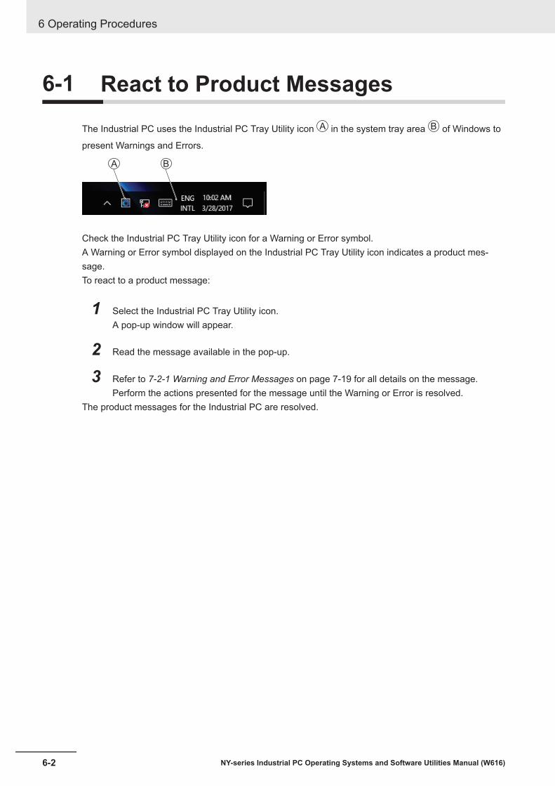
6-1 React to Product Messages
The Industrial PC uses the Industrial PC Tray Utility icon A in the system tray area B of Windows to
present Warnings and Errors.
A B
Check the Industrial PC Tray Utility icon for a Warning or Error symbol.A Warning or Error symbol displayed on the Industrial PC Tray Utility icon indicates a product mes-sage.To react to a product message:
1 Select the Industrial PC Tray Utility icon.A pop-up window will appear.
2 Read the message available in the pop-up.
3 Refer to 7-2-1 Warning and Error Messages on page 7-19 for all details on the message.Perform the actions presented for the message until the Warning or Error is resolved.
The product messages for the Industrial PC are resolved.
6 Operating Procedures
6-2 NY-series Industrial PC Operating Systems and Software Utilities Manual (W616)

6-2 React to Windows Messages
Windows uses the Windows Action Center icon A in the system tray area B of Windows to present
Warnings and Errors.
AB A B
Windows 10 Windows 7
Check the Windows Action Center icon for a Warning or Error symbol.A Warning or Error symbol displayed on the Windows Action Center icon indicates a Windows mes-sage.To react to a Windows message:
1 Open the Windows Action Center.• For Windows 10: Click the Windows Action Center icon.• For Windows 7: Right-click the Windows Action Center icon and select Open Action Center
from the pop-up window.A pop-up window will appear.
Windows 10 Windows 7
2 Read the message available in the window.
3 Perform the actions until each Warning or Error is resolved.The Windows messages for the Industrial PC are resolved.
6 Operating Procedures
6-3NY-series Industrial PC Operating Systems and Software Utilities Manual (W616)
6-2 React to W
indows M
essages
6

6 Operating Procedures
6-4 NY-series Industrial PC Operating Systems and Software Utilities Manual (W616)

7Maintenance
This section provides an overview of the software maintenance tasks for the IndustrialPC.
The hardware maintenance tasks are available in the hardware manuals.
Information is available in related manuals.• For NYB£ refer to NY-series Industrial Box PC Hardware User’s Manual (Cat. No.
W553)• For NYP£ refer to NY-series Industrial Panel PC Hardware User’s Manual (Cat. No.
W555)
7-1 Preventive Maintenance ................................................................................ 7-27-1-1 Preventive Maintenance Schedule.................................................................. 7-27-1-2 Keep Software Updated .................................................................................. 7-27-1-3 Create Backup and Repair Data ..................................................................... 7-37-1-4 Check the Storage Device Status ................................................................. 7-157-1-5 Check the Backup and Repair Media............................................................ 7-17
7-2 Corrective Maintenance............................................................................... 7-197-2-1 Warning and Error Messages........................................................................ 7-197-2-2 Restore and Repair Data............................................................................... 7-207-2-3 Allocate a Drive in Windows.......................................................................... 7-287-2-4 Windows Event Viewer.................................................................................. 7-297-2-5 Windows Low on Memory ............................................................................. 7-317-2-6 Windows Blue Screens ................................................................................. 7-327-2-7 Correct Display Functionality when Nothing is Displayed ............................. 7-327-2-8 Correct Touchscreen Functionality ................................................................ 7-337-2-9 Correct a RAID Array .................................................................................... 7-37
7-1NY-series Industrial PC Operating Systems and Software Utilities Manual (W616)
7

7-1 Preventive MaintenancePreventive Maintenance covers all actions that prevent downtime.
7-1-1 Preventive Maintenance SchedulePrevent unscheduled downtime with the following preventive maintenance schedule.
Daily ReferenceCheck Industrial PC status Refer to 7-2-1 Warning and Error Messages on page 7-19 for all availa-
ble messages.
Weekly ReferenceEnsure you have the latest soft-ware updates
Refer to 7-1-2 Keep Software Updated on page 7-2 for update details.
When changing applications orconfigurations Reference
Create a backup of the IndustrialPC
Refer to 7-1-3 Create Backup and Repair Data on page 7-3 for backupdetails.
Periodically but at least every 6months Reference
Check the status of storage devi-ces.
Refer to 7-1-4 Check the Storage Device Status on page 7-15 for de-tails.
Check the backup and repair me-dia.
Refer to 7-1-5 Check the Backup and Repair Media on page 7-17 for de-tails.
7-1-2 Keep Software UpdatedAlways keep software at the latest released version to ensure stable operation.This is specifically important for:• Anti-virus software• Firewall software• Internet browser• Windows security patches• OMRON software
Precautions for Correct Use
After an OS update or a peripheral device driver update for the product is executed, the productbehavior might be different. Confirm that operation is correct before you start actual operation.
Additional Information
• Refer to Internet Browser for Browser details.• Refer to 5-1-2 Firewall on page 5-3 for Firewall details.• Refer to 5-1-3 Anti-virus Software on page 5-3 for Anti-virus details.
7 Maintenance
7-2 NY-series Industrial PC Operating Systems and Software Utilities Manual (W616)

7-1-3 Create Backup and Repair DataEnsure the operating system, software and data can always be restored when required.There are different software tools to create a backup and repair data.Refer to Overview of Recover, Restore and Repair Methods on page 7-3 for an overview of the pos-sibilities and their goals and requirements.
Precautions for Correct Use
Create backups according to the preventive maintenance schedule to prevent data loss andsystem integrity issues.Refer to 7-1-1 Preventive Maintenance Schedule on page 7-2 for intervals.
Select the Backup and Repair procedure or procedures that are most suitable for your situation.
Overview of Recover, Restore and Repair MethodsDepending on the goal and depending on the available backup and repair data an applicable backupand recover, restore or repair action can be selected.
An overview of the different methods to restore and repair Windows and custom files:
Tool Goal Preparation inadvance Restore details Refer to
OmronRescue Disk
Restore the• Windows par-
tition• Boot partition• MBR = GPT
Create a Res-cue Disk
• A partial recovery or re-covery of user data isnot possible
• The IPC recovers tothe state of the previ-ously created RescueDisk image
• Uses a USB storagedevice
Prepare: Create a NewRescue Disk with theRescue Disk Creator onpage 7-7Create: Create a SystemBackup with the RescueDisk on page 7-5Check: Check the SystemBackup Information on theRescue Disk on page7-17Restore: Restore a Sys-tem Backup with the Res-cue Disk on page 7-21
WindowsSystem Repairdisk
Restore Win-dows 7 to a pre-vious state
Create a Win-dows SystemRepair disk
• A partial recovery or re-covery of user data isnot possible
• Windows recovers tothe state of the previ-ously created Repairdisk image
• Uses a DVD• The IPC can boot with
this disk
Create: Create a Win-dows 7 System RepairDiskCheck: Check the SystemRepair Disk (Windows)Restore: Repair Windows7 with the System RepairDisk
7 Maintenance
7-3NY-series Industrial PC Operating Systems and Software Utilities Manual (W616)
7-1 Preventive Maintenance
7
7-1-3 Create Backup and R
epair Data

Tool Goal Preparation inadvance Restore details Refer to
Windows Re-covery disk
Restore Win-dows 10 to aprevious state
Create a Win-dows Recoverydisk
• A partial recovery or re-covery of user data isnot possible
• Windows recovers tothe state of the previ-ously created Recoveryimage
• Uses a USB storagedevice
• The IPC can boot withthis USB
Create: Create a Win-dows 10 Recovery Driveon page 7-10Restore: Recover Win-dows 10 with the Recov-ery Drive on page 7-27
WindowsBackup and Re-store
Restore a user'sselection of fold-ers
Create a Win-dows Backup
• The data is restored tothe state of the previ-ously created backup
• Recovery of specificfolders is possible.Backups can be creat-ed automatically at pre-defined intervals
• No recovery of the Win-dows operating system
• Uses any type of stor-age device
Create: Create a CustomBackup with WindowsBackup on page 7-12Check: Check the Cus-tom Backup Storage De-vice (Windows) on page7-17Restore: Restore a Cus-tom Backup with Windowson page 7-23
Additional Information
Contact your OMRON representative when the IPC needs to be restored and you do not haveany restore or recover possibility.
7 Maintenance
7-4 NY-series Industrial PC Operating Systems and Software Utilities Manual (W616)
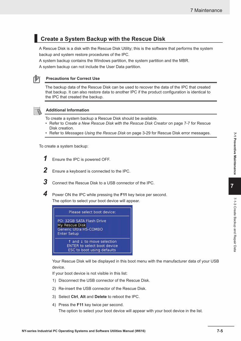
Create a System Backup with the Rescue DiskA Rescue Disk is a disk with the Rescue Disk Utility; this is the software that performs the systembackup and system restore procedures of the IPC.A system backup contains the Windows partition, the system partition and the MBR.A system backup can not include the User Data partition.
Precautions for Correct Use
The backup data of the Rescue Disk can be used to recover the data of the IPC that createdthat backup. It can also restore data to another IPC if the product configuration is identical tothe IPC that created the backup.
Additional Information
To create a system backup a Rescue Disk should be available.• Refer to Create a New Rescue Disk with the Rescue Disk Creator on page 7-7 for Rescue
Disk creation.• Refer to Messages Using the Rescue Disk on page 3-29 for Rescue Disk error messages.
To create a system backup:
1 Ensure the IPC is powered OFF.
2 Ensure a keyboard is connected to the IPC.
3 Connect the Rescue Disk to a USB connector of the IPC.
4 Power ON the IPC while pressing the F11 key twice per second.The option to select your boot device will appear.
Your Rescue Disk will be displayed in this boot menu with the manufacturer data of your USBdevice.If your boot device is not visible in this list:
1) Disconnect the USB connector of the Rescue Disk.
2) Re-insert the USB connector of the Rescue Disk.
3) Select Ctrl, Alt and Delete to reboot the IPC.
4) Press the F11 key twice per second.The option to select your boot device will appear with your boot device in the list.
7 Maintenance
7-5NY-series Industrial PC Operating Systems and Software Utilities Manual (W616)
7-1 Preventive Maintenance
7
7-1-3 Create Backup and R
epair Data

5 Use the arrow keys to select the Rescue Disk and then select Enter.The menu window opens.The mentioned number can be different from the number displayed on your screen.
Welcome to the Rescue Disk Utility . , what would you like to do?
Create BackupRestore BackupBackup informationStorage device informationExit
6 Select Create Backup.The backup confirmation window opens.
For:• NY£££- ££1• NY£££- ££2
or For NY£££- ££3
For NY£££- ££4
Partition table, Boot, MSR and Windows partitions will be backed up.
Continue Return
Windows 7 Windows 10
7 Select Continue to start the system backup process.Wait until the message Backup finished appears.
8 The message Would you like to enter an optional comment for the created backup? givesthe option to add an extra remark to the created backup.Select No to exit without an optional comment.Select Yes to add the optional comment. Add the comment and press [Enter] to finalize thebackup creation.
9 Select OK to return to the main menu.
10 Select Exit to close the Rescue Disk Utility.The IPC will power OFF.
11 Remove the Rescue Disk and store it in a safe place.A system backup is created on the Rescue Disk.
Precautions for Correct Use
Create backups according to the preventive maintenance schedule to prevent data loss andsystem integrity issues.Refer to 7-1-1 Preventive Maintenance Schedule on page 7-2 for intervals.
Additional Information
Refer to Restore a System Backup with the Rescue Disk on page 7-21 for system restore de-tails.
7 Maintenance
7-6 NY-series Industrial PC Operating Systems and Software Utilities Manual (W616)

Create a New Rescue Disk with the Rescue Disk CreatorA Rescue Disk is a disk with the Rescue Disk Utility that enables users to create a system backupand to do a system restore.A system backup contains the Windows partition, the system partition and the MBR.
Prepare:• The Rescue Disk Creator
Refer to 3-6-3 Installation on page 3-26 for installation details.Refer to Error Messages Creating the Rescue Disk on page 3-28 for message details.
• A USB storage device that has sufficient capacity to backup the content of the IPC. The capacityshould be at least the Windows partition size + 16 GB. The recommended minimum read/writespeed is 190 MB/s.Note that all content on this USB storage device will be erased during the Rescue Disk creation.
Use the following procedure to create a new Rescue Disk:
1 Connect a USB storage device that has sufficient capacity to backup the content of the IPC.
2 Select the Windows Start Button.
3 In the search field, input Rescue.
4 Right-click Rescue Disk Creator and then select Run as administrator.The Rescue Disk Creator Utility window opens.
Version Information
Specifications and functionality can change between different versions of the Rescue Disk Cre-ator Utility. This can result in changes in the content of the Utility window.
5 Select the connected USB storage device at Target disk:.Refer to 3-6-5 Messages on page 3-27 for message details if required.The button Create Rescue Disk will be enabled as soon as a USB storage device is detectedand accepted.
7 Maintenance
7-7NY-series Industrial PC Operating Systems and Software Utilities Manual (W616)
7-1 Preventive Maintenance
7
7-1-3 Create Backup and R
epair Data

6 Select the Create Rescue Disk button to start the creation process.Wait until the progress bar shows the Rescue Disk creation finished.Refer to 3-6-5 Messages on page 3-27 for message details if required.
7 Select Close to close the Rescue Disk Creator.The Rescue Disk is available but it is still empty, there is no system backup on the Rescue Disk.Next step is to create a system backup with this Rescue Disk.
Additional Information
• Refer to Create a System Backup with the Rescue Disk on page 7-5 for system backup de-tails.
• Refer to Restore a System Backup with the Rescue Disk on page 7-21 for system restoredetails.
Create a Windows 7 System Repair DiskA Windows System Repair Disk can repair Windows if a serious error occurs.
Additional Information
To create a Windows System Repair Disk, a separate Windows PC with a DVD writer is re-quired that has the same Windows edition and System type as the Industrial PC. The WindowsSystem Repair Disk can not be created with the Industrial PC.
Prepare:• A PC with a DVD writer that has the same Windows edition and System type as your IPC.
• An example of the Windows edition is "Windows 7" with "Service Pack 1".• An example of the System type is "64-bit Operating System".
• An empty DVDUse the Windows Backup and Restore mechanisms on the PC with a DVD writer to create a systemrepair disk.
To create a Windows System Repair Disk:
1 Start the PC that has a DVD writer and login.
2 Select the Windows Start Button.
3 In the search field, input Backup.
4 Select Backup and Restore.The Backup and Restore window opens.
7 Maintenance
7-8 NY-series Industrial PC Operating Systems and Software Utilities Manual (W616)

5 Select Create a system repair disk.The Create a system repair disk window opens.
6 Select the applicable drive letter of the DVD writer and then select Create disk.
7 Wait until the disk is created and the remove it and store it in a safe place.
Additional Information
Refer to http://windows.microsoft.com/ for Backup and Restore details.
7 Maintenance
7-9NY-series Industrial PC Operating Systems and Software Utilities Manual (W616)
7-1 Preventive Maintenance
7
7-1-3 Create Backup and R
epair Data

Create a Windows 10 Recovery DriveA Windows recovery drive can repair Windows if a serious error occurs.Prepare:• A USB storage device that has sufficient capacity to backup the content of the IPC. The capacity
should be at least the Windows partition size + 16 GB. The recommended minimum read/writespeed is 190 MB/s.Note that all content on this USB storage device will be erased.
Use the following procedure to create a Windows recovery drive:
1 Insert the USB storage device in a USB 3.0 connector.
2 Select the Windows Start Button.
3 In the search field, input recovery drive.
4 Select Create a recovery drive.The recovery drive window opens.
5 Check the checkbox Back up system files to the recovery drive and then select Next.The drive selection window opens.
E:\MyUSB
6 Select the applicable drive letter and then select Next.The Create window will appear.
7 Maintenance
7-10 NY-series Industrial PC Operating Systems and Software Utilities Manual (W616)

7 Read the warning and if your personal files are safe then select Create.
8 Wait until the progress bar is finished and the message The recovery drive is ready appears.
9 Remove the USB storage device and store it in a safe place.
The Windows recovery drive is ready.
Additional Information
Refer to http://windows.microsoft.com/ for recovery drive details.
7 Maintenance
7-11NY-series Industrial PC Operating Systems and Software Utilities Manual (W616)
7-1 Preventive Maintenance
7
7-1-3 Create Backup and R
epair Data
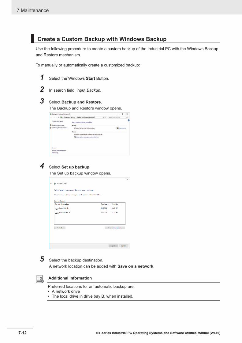
Create a Custom Backup with Windows BackupUse the following procedure to create a custom backup of the Industrial PC with the Windows Backupand Restore mechanism.
To manually or automatically create a customized backup:
1 Select the Windows Start Button.
2 In search field, input Backup.
3 Select Backup and Restore.The Backup and Restore window opens.
4 Select Set up backup.The Set up backup window opens.
5 Select the backup destination.A network location can be added with Save on a network.
Additional Information
Preferred locations for an automatic backup are:• A network drive• The local drive in drive bay B, when installed.
7 Maintenance
7-12 NY-series Industrial PC Operating Systems and Software Utilities Manual (W616)

6 Select Next.The following window will appear:
7 Select Let me choose and then select Next.The following window will appear:
8 Select all directories you want to include in the backup.
9 Select Next.
7 Maintenance
7-13NY-series Industrial PC Operating Systems and Software Utilities Manual (W616)
7-1 Preventive Maintenance
7
7-1-3 Create Backup and R
epair Data

10 Select Configure schedule or Change schedule and change the backup schedule.Ensure:• The interval is short enough to minimize data loss when a restore is required• The Industrial PC is powered ON during the backup periods• The time the backup is scheduled does not interfere with normal operationor uncheck Run backup on a schedule if an automatic backup is not possible.
11 Select OK.
12 Select Save settings and run backup to create the first backup.
Precautions for Correct Use
Create backups according to the preventive maintenance schedule to prevent data loss andsystem integrity issues.Refer to 7-1-1 Preventive Maintenance Schedule on page 7-2 for intervals.
Additional Information
• Check your backup to ensure it contains all data required for a restore.• Refer to http://windows.microsoft.com/ for Backup and Restore details.• Refer to Restore a Custom Backup with Windows on page 7-23 for the Restore Procedure.
7 Maintenance
7-14 NY-series Industrial PC Operating Systems and Software Utilities Manual (W616)

7-1-4 Check the Storage Device StatusThe Rescue Disk is a disk with the Rescue Disk Utility; this software can display the status of all Om-ron-approved storage devices.
Version Information
The device status information is only available for products with an Atom CPU. The RescueDisk Utility should be version 0001.0000 or higher.Refer to 1-4 Product Configuration on page 1-5 for details.
Additional Information
To check the status of a storage device a Rescue Disk should be available.• Refer to Create a New Rescue Disk with the Rescue Disk Creator on page 7-7 for Rescue
Disk creation.• Refer to Messages Using the Rescue Disk on page 3-29 for Rescue Disk error messages.
To check the status of a storage device:
1 Ensure the IPC is powered OFF.
2 Ensure a keyboard is connected to the IPC.
3 Connect the Rescue Disk to a USB connector of the IPC.
4 Power ON the IPC while pressing the F11 key twice per second.The option to select your boot device will appear.
Your Rescue Disk will be displayed in this boot menu with the manufacturer data of your USBdevice.If your boot device is not visible in this list:
1) Disconnect the Rescue Disk from the USB connector of the IPC.
2) Re-connect the Rescue Disk to the IPC.
3) Select Ctrl, Alt and Delete to reboot the IPC.
4) Press the F11 key twice per second.The option to select your boot device will appear with your boot device in the list.
7 Maintenance
7-15NY-series Industrial PC Operating Systems and Software Utilities Manual (W616)
7-1 Preventive Maintenance
7
7-1-4 Check the Storage D
evice Status

5 Use the arrow keys to select the Rescue Disk and then select Enter.The Rescue Disk window opens.
Welcome to the Rescue Disk Utility . , what would you like to do?
Create BackupRestore BackupBackup informationStorage device informationExit
Where £.£ displays the version of the Rescue Disk.
6 Select Storage device information.The storage devices information window opens.
Storage device information: IPC model: NY512-1300-1XX214K1D === 1 === Storage device name: sda Storage device type: 32 GB SATA Flash Storage device state: operational Storage device firmware: L17606
OK
7 Check the storage device state and take action when required.
Storage devicestate Description Action
unknown Storage device state could not be deter-mined
Contact your OMRON representativefor further support
operational Storage device state is in operationalmode and functioning normally
Storage device functioning normally, noaction required
pre-maintenance Storage device state is in pre-mainte-nance mode and functioning normally
Storage device replacement should bescheduled
maintenance Storage device state is in maintenancemode and functioning normally
Storage device replacement is required
critical Storage device state is in critical modeand normal operation cannot be guar-anteed
Storage device should be replaced im-mediately as normal operation cannotbe guaranteed
8 Select OK to return to the main menu.
9 Select Exit to close the Rescue Disk Utility.
10 Remove the Rescue Disk and store it in a safe place.
The storage device status is known.
7 Maintenance
7-16 NY-series Industrial PC Operating Systems and Software Utilities Manual (W616)

7-1-5 Check the Backup and Repair MediaUse the following procedure to check the backup or repair media.
Check the System Backup Information on the Rescue DiskUse the following procedure to check the rescue disk for the system backup.
1 Use the rescue disk to boot the IPC.Refer to Restore a System Backup with the Rescue Disk on page 7-21 for details.Follow the first few steps of the procedure until following screen appears:
2 Select Backup information and then Enter.Following screen will appear:
Backup created on Fri Dec 1 12:34:56
Model name : NY512-1300 Serial number : 0123 Lot number : 01234N Content : MBR, Boot, Windows and Machine Control partitions Unit version : V1.16.00 OSB version : 0000.0016 Comment by user : demo for manual - your content will be different
Current System:
Model name : NY Serial number : 0123 Lot number : 01234N Unit version : V1.16.00 OSB version : 0000.0016
OK
3 Check the content. If there is no content then there is no usable backup on this Rescue Disk.
4 Select Exit.The rescue disk information is checked.
Check the Custom Backup Storage Device (Windows)Use the following procedure to check the custom backup storage device.
1 Insert the storage device with the backup in the Industrial PC that created the backup.
2 Follow the first few steps of the restore procedure to display the 'Restore files' screen.Refer to Restore a Custom Backup with Windows on page 7-23 for details.
3 Browse the storage device and ensure at least one backup is displayed.
4 Select Cancel to cancel the restore procedure.The storage device with the custom backup is approved.
7 Maintenance
7-17NY-series Industrial PC Operating Systems and Software Utilities Manual (W616)
7-1 Preventive Maintenance
7
7-1-5 Check the Backup and R
epair Media
Check the System Repair Disk (Windows)Use the following procedure to check the system repair disk to repair Windows.
1 Follow the first few steps of the repair procedure to display the recovery software screen to se-lect your keyboard language.Refer to Repair Windows 7 with the System Repair Disk on page 7-26 for details.
2 Exit the recovery software.The backup medium for the system repair disk is approved.
7 Maintenance
7-18 NY-series Industrial PC Operating Systems and Software Utilities Manual (W616)

7-2 Corrective MaintenanceCorrective maintenance covers all actions to correct problems that cause downtime.
WARNINGDo not attempt to disassemble, repair, or modify the product in any way. Doing so mayresult in malfunction or fire.
Contact your local OMRON representative if the corrective maintenance actions did not solve theproblem.
7-2-1 Warning and Error MessagesWarning and Error messages are provided by the Industrial PC when there is a potential problem thatmay cause downtime. This section provides details about these messages.Warning messages inform you about a situation that will lead to downtime of the Industrial PC.Error messages inform you about what caused the downtime of the Industrial PC.
The following message channels are available.
LED IndicatorsThe ERR LED indicator provides information on warnings and errors.
Industrial PC Support UtilityThe Industrial PC Support Utility provides information on warnings and errors.
The Industrial PC Support Utility indicates:• Internal temperature above setting
Check the status of the Fan Unit and check the ambient conditions.• Low revolution speed of the Fan Unit
• Check for excessive dust on the fans and in the Fan Unit.• If required replace the Fan Unit.
• Low battery statusReplace the battery.
7 Maintenance
7-19NY-series Industrial PC Operating Systems and Software Utilities Manual (W616)
7-2 Corrective M
aintenance
7
7-2-1 Warning and Error M
essages

Windows Action CenterThe Windows Action Center provides information on Windows related warnings and errors.
The Windows Action Center indicates security and maintenance issues.Some examples:• Virus protection (Important)
Windows did not find anti-virus software on this computer.• Windows Update (Important)
windows Update is not set up for this computer.• Set up backup
Your files are not being backed up.
Windows Pop Up WindowWindows Pop Up windows provide information on Windows issues.
An example of a Windows Pop Up
• Close programs to prevent information loss.
To solve this change the paging file size.
7-2-2 Restore and Repair DataDepending on the goal and depending on the available backup and repair data an applicable restoreor repair action can be selected.
Use the Overview of Recover, Restore and Repair Methods on page 7-3 to determine the method thatis applicable to your situation.Refer to the mentioned procedure to perform the restore or repair procedure.
7 Maintenance
7-20 NY-series Industrial PC Operating Systems and Software Utilities Manual (W616)

Restore a System Backup with the Rescue DiskA Rescue Disk is a disk with the Rescue Disk Utility; this is the software that performs the backup andrestore procedures.Use the Rescue Disk to restore the system backup. This will restore the Windows partition, the systempartition and the MBR to the moment the Rescue Disk backup was created.
Precautions for Correct Use
The backup data of the Rescue Disk can be used to recover the data of the IPC that createdthat backup. It can also restore data to another IPC if the product configuration is identical tothe IPC that created the backup.
Additional Information
To restore a system backup, a Rescue Disk with a system backup should be available.• Refer to Create a New Rescue Disk with the Rescue Disk Creator on page 7-7 for Rescue
Disk creation details.• Refer to Create a System Backup with the Rescue Disk on page 7-5 for system backup de-
tails.• Refer to Messages Using the Rescue Disk on page 3-29 for Rescue Disk error messages.
To restore a system backup:
1 Ensure the IPC is powered OFF.
2 Ensure a keyboard is connected to the IPC.
3 Connect the Rescue Disk to a USB connector of the IPC.
4 Power ON the IPC while pressing the F11 key twice per second.The option to select your boot device will appear.
Your Rescue Disk will be displayed in this boot menu with the manufacturer data of your USBdevice.If your boot device is not visible in this list:
1) Disconnect the USB connector of the Rescue Disk.
2) Re-insert the USB connector of the Rescue Disk.
3) Select Ctrl, Alt and Delete to reboot the IPC.
4) Press the F11 key twice per second.
7 Maintenance
7-21NY-series Industrial PC Operating Systems and Software Utilities Manual (W616)
7-2 Corrective M
aintenance
7
7-2-2 Restore and R
epair Data

The option to select your boot device will appear with your boot device in the list.
5 Use the arrow keys to select the Rescue Disk and then select Enter.The menu window opens.
Welcome to the Rescue Disk Utility . , what would you like to do?
Create BackupRestore BackupBackup informationStorage device informationExit
The mentioned number in the first line can be different from the number displayed on yourscreen.
6 Select Restore Backup.The restore selection window opens.
For:• NY£££- ££1• NY£££- ££2
or For NY£££- ££
For NY£££- ££4
Select the restore option:
Partition tablePartition table, Boot, MSR and Windows partitions
Return
Windows 7 Windows 10
7 Make your selection to restore the system.The overwrite confirmation window opens.
8 Select Yes to start the system restore process.Wait until the message Restore finished appears.
9 Select OK to return to the main menu.
10 Select Exit to close the Rescue Disk Utility.The IPC will power OFF.
11 Remove the Rescue Disk and store it in a safe place.The system backup of the IPC is restored.
Additional Information
• Refer to Create a New Rescue Disk with the Rescue Disk Creator on page 7-7 for RescueDisk creation details.
• Refer to Create a System Backup with the Rescue Disk on page 7-5 for system backup de-tails.
7 Maintenance
7-22 NY-series Industrial PC Operating Systems and Software Utilities Manual (W616)
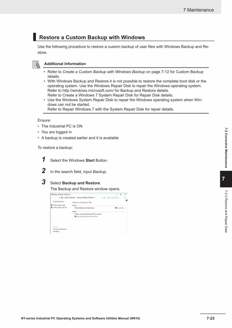
Restore a Custom Backup with WindowsUse the following procedure to restore a custom backup of user files with Windows Backup and Re-store.
Additional Information
• Refer to Create a Custom Backup with Windows Backup on page 7-12 for Custom Backupdetails.
• With Windows Backup and Restore it is not possible to restore the complete boot disk or theoperating system. Use the Windows Repair Disk to repair the Windows operating system.Refer to http://windows.microsoft.com/ for Backup and Restore details.Refer to Create a Windows 7 System Repair Disk for Repair Disk details.
• Use the Windows System Repair Disk to repair the Windows operating system when Win-dows can not be started.Refer to Repair Windows 7 with the System Repair Disk for repair details.
Ensure:• The Industrial PC is ON• You are logged in• A backup is created earlier and it is available
To restore a backup:
1 Select the Windows Start Button.
2 In the search field, input Backup.
3 Select Backup and Restore.The Backup and Restore window opens.
7 Maintenance
7-23NY-series Industrial PC Operating Systems and Software Utilities Manual (W616)
7-2 Corrective M
aintenance
7
7-2-2 Restore and R
epair Data

4 Select Restore my files.The restore files window opens.
5 Use the buttons Search and Browse for files or Browse for folders to find the created back-up.
6 Add the files and folders to be restored and then select Next.
Additional Information
With this Windows Restore procedure it is not possible to restore files that are in use. Thismeans system files and files of the logged in user can not be restored with this procedure.Refer to Repair Windows 7 with the System Repair Disk for Windows Repair details.
7 Maintenance
7-24 NY-series Industrial PC Operating Systems and Software Utilities Manual (W616)

7 Select In the original location and then select Next.The progress window will appear.
8 Wait until the message Your files have been restored appears and then select Finish.
The files are restored.
7 Maintenance
7-25NY-series Industrial PC Operating Systems and Software Utilities Manual (W616)
7-2 Corrective M
aintenance
7
7-2-2 Restore and R
epair Data

Repair Windows 7 with the System Repair DiskUse the following procedure to repair the Windows operating system with a System Repair Disk.
Ensure:• The Industrial PC is powered OFF.• A System Repair Disk is created earlier and it is available.
To perform a system repair:
1 Connect a USB keyboard, a USB mouse and a USB external DVD drive to the Industrial PC.
2 Power ON the Industrial PC and immediately press the F11 key repeatedly.
3 Insert the System Repair Disk in the DVD drive.
4 Select DVD Drive as boot device and press Enter.The message Windows is loading files ... and a progress bar appear.
5 Press any key to start and wait until the recovery software started.
6 Select your keyboard language and then select Next.The System Recovery Options window appears.
7 Select Restore your computer using a system image that you created earlier and selectNext.
8 Select Use latest available system image and then select Next.The Re-Image Your Computer window appears.
9 Do not change the setting to restore C: , select Next.
10 Review the settings and select Finish.
11 Wait until the repair process is finished, this can take several hours.
12 Restart the Industrial PC.Windows is repaired.
Additional Information
• Refer to http://windows.microsoft.com/ for System repair details.• Refer to Create a Windows 7 System Repair Disk on page 7-8 for System Repair disk crea-
tion.• Refer to 5-3 Create Backup and Repair Media on page 5-6 for Backup creation.
7 Maintenance
7-26 NY-series Industrial PC Operating Systems and Software Utilities Manual (W616)
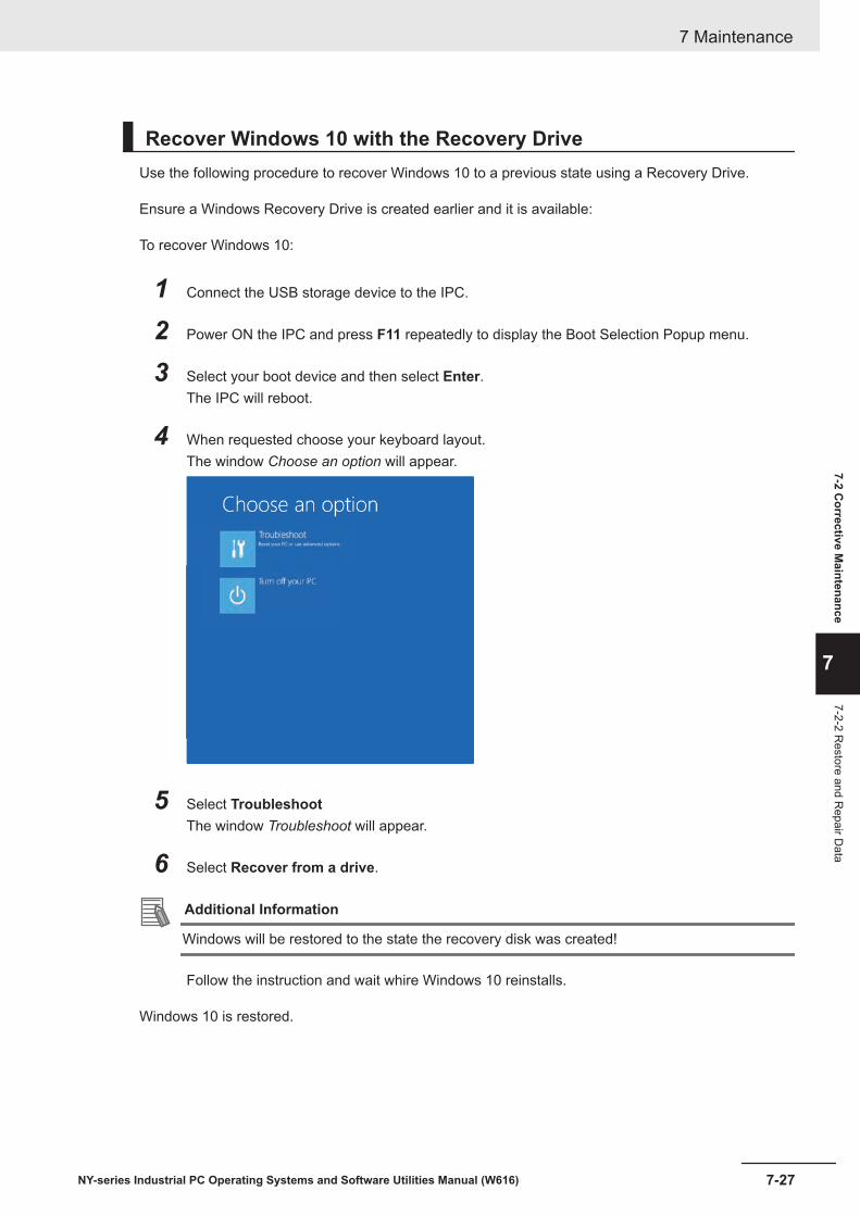
Recover Windows 10 with the Recovery DriveUse the following procedure to recover Windows 10 to a previous state using a Recovery Drive.
Ensure a Windows Recovery Drive is created earlier and it is available:
To recover Windows 10:
1 Connect the USB storage device to the IPC.
2 Power ON the IPC and press F11 repeatedly to display the Boot Selection Popup menu.
3 Select your boot device and then select Enter.The IPC will reboot.
4 When requested choose your keyboard layout.The window Choose an option will appear.
5 Select TroubleshootThe window Troubleshoot will appear.
6 Select Recover from a drive.
Additional Information
Windows will be restored to the state the recovery disk was created!
Follow the instruction and wait whire Windows 10 reinstalls.
Windows 10 is restored.
7 Maintenance
7-27NY-series Industrial PC Operating Systems and Software Utilities Manual (W616)
7-2 Corrective M
aintenance
7
7-2-2 Restore and R
epair Data

7-2-3 Allocate a Drive in WindowsAn added drive must be allocated before it becomes visible in Windows.To allocate a drive in Windows:
1 Ensure the IPC is ON.
2 Select the Windows Start Button.
3 In the search field, input partition.
4 Select Create and format hard disk partitions.The Disk Management window opens. The new disk is displayed with a storage spaceUnallocated.
5 Right-click on the unallocated space and select New Simple Volume.The New Simple Volume Wizard opens.
6 Follow the steps in the New Simple Volume Wizard.The drive is installed and ready for use in Windows under the configured drive letter.
Additional Information
Do not format, resize or change settings for partition C:. Windows is installed on drive partitionC: and any change to this partition can cause Windows to stop working.
7 Maintenance
7-28 NY-series Industrial PC Operating Systems and Software Utilities Manual (W616)

7-2-4 Windows Event ViewerThe Windows Event Viewer displays logged events.These logged events can support you in corrective maintenance.
1 Select the Windows Start Button.
2 In the search field, input Event.
3 Select View event logs.The Event Viewer opens.
A B C D
ItemA Selection treeB Event listC Event detailsD Action list
4 In the Selection tree expand Windows Logs and select Application.The Event list will display the Events.
5 Select the heading Source to sort the event messages per application.
6 Scroll to the event you want to investigate.Refer to the section 'Logging' of a specific utility for more details.
7 Maintenance
7-29NY-series Industrial PC Operating Systems and Software Utilities Manual (W616)
7-2 Corrective M
aintenance
7
7-2-4 Window
s Event Viewer

7 Select the event to display details in the Event details window or to take action in the Actionoverview window.
Filter Events and Event DetailsThis procedure explains how to filter events in the Windows event log.To filter the events:
1 Open the Windows Event Viewer.Refer to 7-2-4 Windows Event Viewer on page 7-29 for details.
2 In the Actions list select Filter Current Log.The Filter Current Log page opens.
3 Input the desired filters and select OK.
4 The filtered events will appear in Event list of the Event Viewer.Select an event in the Event list to display Event details in the Event details part of the EventViewer.
The filtered events are available including the details per event.
7 Maintenance
7-30 NY-series Industrial PC Operating Systems and Software Utilities Manual (W616)

7-2-5 Windows Low on MemoryThe Windows memory can become low when adding applications and/or updates.When the memory is low a new window with the message Close programs to prevent information losswill appear.Increase the paging file size to solve this problem.
To increase the page file size:
1 Select the Windows Start Button.
2 In the search field, input advanced system settings.
3 Select View advanced system settings.The Advanced tab page in the Windows System properties will appear.
4 In the group Performance, select the Settings... Button.The Performance options window will appear.
5 Select the Advanced tab page.
6 In the group Virtual memory, select the Change... Button.
7 Select the checkbox Automatically manage paging file size for all drives.
8 Select the OK Button to save this setting.
Precautions for Safe Use
Virtual memory settings can affect the performance of the system. Disable the paging file afterinstallation of applications or updates.
7 Maintenance
7-31NY-series Industrial PC Operating Systems and Software Utilities Manual (W616)
7-2 Corrective M
aintenance
7
7-2-5 Window
s Low on M
emory

7-2-6 Windows Blue ScreensA blue screen will appear if Windows crashes.
Possible solutions for repetitive blue screens:
1 Install the latest updates of Windows.
2 Install the latest device drivers.
3 If changes to the system were made: Undo recent hardware changes, undo recent driver up-dates and then roll back system to latest working state.
Additional Information
• Windows 10: Refer to https://support.microsoft.com/en-us/help/14238/windows-10-trouble-shoot-blue-screen-errors for details.
• Windows 7: Refer to http://windows.microsoft.com/en-us/windows7/resolving-stop-blue-screen-errors-in-windows-7 for details.
• For troubleshooting an external boot device might be handy.
7-2-7 Correct Display Functionality when Nothing is DisplayedWhen it seems the display is not functional, check the ERR LED.• If the ERR LED is OFF
• Check if the power supply is present.• Check if the brightness setting is not too low.
• If the ERR LED is blinking check if the IPC is not in standby mode.• If the ERR LED is ON
• Check if the power supply voltage is inside specifications.• Check if the ambient temperature is inside specifications.• Check if the Fan Unit has no warning messages.
Refer to the ERR LED for message details.• Check if a watchdog error occurred.
The watchdog is disabled by default and can only be enabled by software using the Industrial PCSystem API.
7 Maintenance
7-32 NY-series Industrial PC Operating Systems and Software Utilities Manual (W616)

7-2-8 Correct Touchscreen FunctionalityThe touchscreen functionality can have several unwanted situations.
1. With one display:• No touch response
Refer to Correct Touchscreen Functionality with No Touch Response on page 7-33 for details.• The touch response is at a different position than the actual touch
Refer to Calibrate Touchscreen on page 7-34 for details.
2. With more than one display:When other monitors are connected it is possible the touch actions on the touchscreen monitorshow a response on another monitor.Refer to Correct Touchscreen Functionality with Multiple Monitors on page 7-35 for details.
Correct Touchscreen Functionality with No Touch ResponseWhen the touchscreen functionality is not functional, check:• Water present on the display surface.
Wipe the display surface with a dry lint free cloth.• When using gloves, ensure to use gloves that had no problems when the touch functionality was
functional.
7 Maintenance
7-33NY-series Industrial PC Operating Systems and Software Utilities Manual (W616)
7-2 Corrective M
aintenance
7
7-2-8 Correct Touchscreen Functionality

Calibrate TouchscreenWhen the resolution of the touchscreen monitor is changed the touch functionality might not scale ac-cordingly. The result is that touching the touchscreen monitor will display the touch at incorrect loca-tions.
Use the following procedure to calibrate the touchscreen functionality of your Industrial PC.
1 Select the Windows Start Button.
2 In the search field, input Tablet.
3 Select Tablet PC Settings.The Tablet PC Settings window opens.
4 Select the Calibrate Button.A window with lines and a touch indicator will appear.
5 Touch the indicator on all locations where it appears.When finished a window appears with the question Do you want to save the calibration data?
6 Select the Yes Button.
7 Check the touchscreen functionality.
The touchscreen functionality is calibrated.
If the Touchscreen can not be corrected then restore the factory settings.Select the Reset button in the Tablet PC Settings window to restore the factory settings.
7 Maintenance
7-34 NY-series Industrial PC Operating Systems and Software Utilities Manual (W616)

Correct Touchscreen Functionality with a PenMount MessageWhen a touchscreen monitor receives incorrect signals the message PenMount Device touch disabledat abnormal state. Please remove palm or water. appears.
Touching the display has no effect.The OK Button will remove the pop-up so the display can be used with a mouse and a keyboard.
Use the following procedure to enable the touchscreen functionality of your Industrial PC.
1 Ensure nothing touches the display.
2 Dry the surface with a soft cloth.
3 Check the touchscreen functionality.
The touchscreen functionality is enabled.
Correct Touchscreen Functionality with Multiple MonitorsWhen more than one monitor is connected then Windows can not determine which monitor has thetouch functionality. The result is that touching the touchscreen monitor can result in actions on a differ-ent connected monitor.
Use the following procedure to correct the touchscreen functionality on monitors of your Industrial PC.
1 Select the Windows Start Button.
2 In the search field, input Tablet.
3 Select Tablet PC Settings.The Tablet PC Settings window opens.
7 Maintenance
7-35NY-series Industrial PC Operating Systems and Software Utilities Manual (W616)
7-2 Corrective M
aintenance
7
7-2-8 Correct Touchscreen Functionality
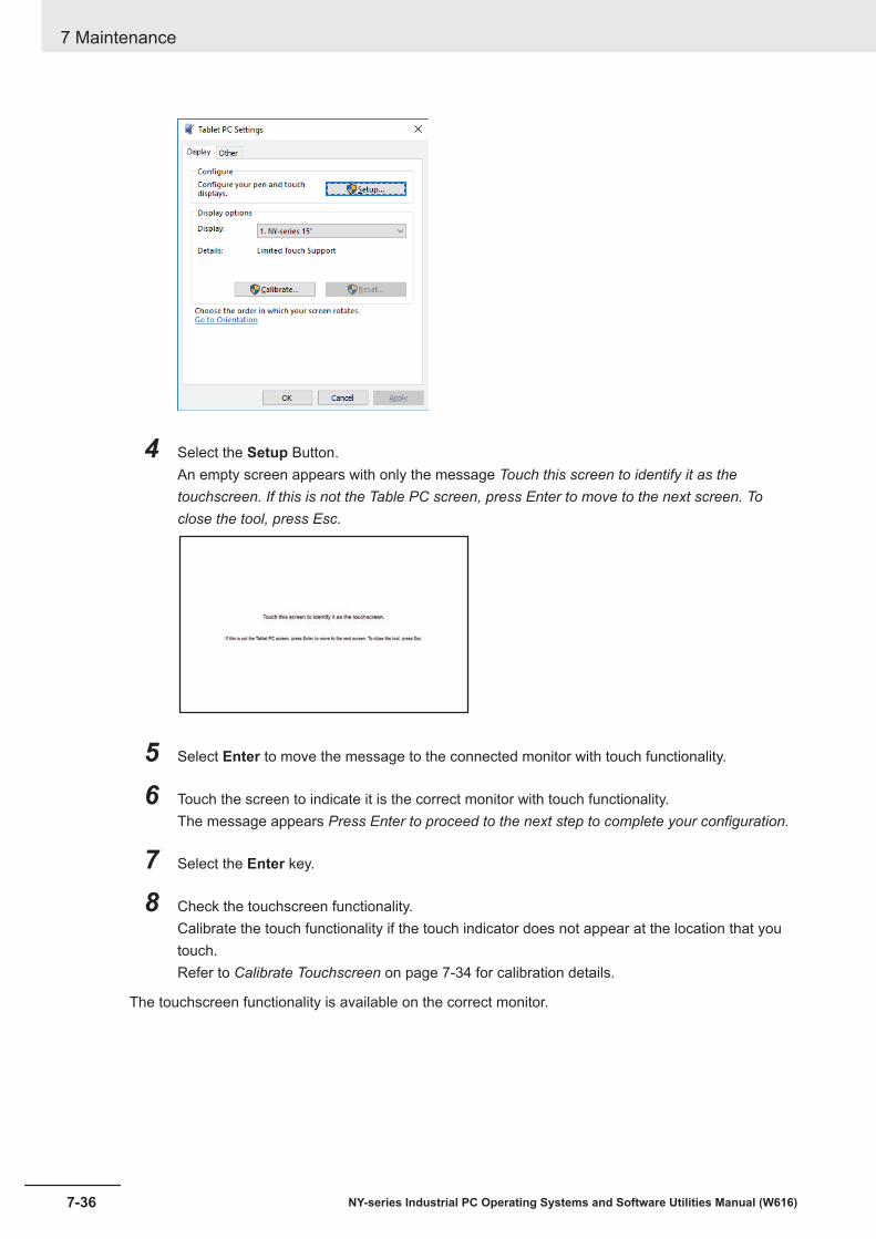
4 Select the Setup Button.An empty screen appears with only the message Touch this screen to identify it as thetouchscreen. If this is not the Table PC screen, press Enter to move to the next screen. Toclose the tool, press Esc.
5 Select Enter to move the message to the connected monitor with touch functionality.
6 Touch the screen to indicate it is the correct monitor with touch functionality.The message appears Press Enter to proceed to the next step to complete your configuration.
7 Select the Enter key.
8 Check the touchscreen functionality.Calibrate the touch functionality if the touch indicator does not appear at the location that youtouch.Refer to Calibrate Touchscreen on page 7-34 for calibration details.
The touchscreen functionality is available on the correct monitor.
7 Maintenance
7-36 NY-series Industrial PC Operating Systems and Software Utilities Manual (W616)
7-2-9 Correct a RAID ArrayCorrection of a RAID array is only applicable to models NY£££-£2£££.A RAID array needs correction if the state is Degraded or Broken.Refer to HW RAID Details on page 3-10 for state details.
Additional Information
To correct a RAID array an empty storage device is required. This empty storage device shouldbe of the same model as the RAID storage devices already present in your IPC.
To correct a RAID array:
1 Check which of the two RAID disks has an error status.
2 Power OFF the IPC.
3 Replace the RAID disk that has the error status.Refer to Replace a Drive in the Hardware User's Manual of your IPC for details.
4 Power ON the IPC.
5 Ensure the RAID state changes to "Normal".Depending on the type and size of your storage device the RAID state change to "Normal"might take several hours.
The RAID state is corrected to Normal.
7 Maintenance
7-37NY-series Industrial PC Operating Systems and Software Utilities Manual (W616)
7-2 Corrective M
aintenance
7
7-2-9 Correct a R
AID Array

7 Maintenance
7-38 NY-series Industrial PC Operating Systems and Software Utilities Manual (W616)

AAppendices
A-1 Customize Windows ..................................................................................... A-2A-1-1 Enhanced Write Filter ......................................................................................A-2A-1-2 File-Based Write Filter .....................................................................................A-3A-1-3 Unified Write Filter ...........................................................................................A-5A-1-4 Trusted Platform Module .................................................................................A-6
A-1NY-series Industrial PC Operating Systems and Software Utilities Manual (W616)
A

A-1 Customize WindowsThis section provides an overview of the tools to customize Windows.
A-1-1 Enhanced Write FilterThe Enhanced Write Filter (EWF) is applicable to IPCs with a Windows 7 operating system.The Enhanced Write Filter (EWF) intercepts disk changes and stores them into a memory overlay inRAM memory instead of applying them to the original volume.
Additional Information
• File-Based Write Filter (FBWF) provides a similar function, but operates at the file level, whileEWF operates at the sector level.
• Refer to the Microsoft Developer Network (MSDN) for detailed information.
AdvantagesEWF and FBWF and UWF provide the following benefits:• Write-protect one or more partitions on a system.• Make it possible to revert changes and revert to the original disk content.• Enable booting from read-only media.
By redirecting all write requests to RAM the run-time maintains the appearance of a writable run-time image.
• Improve the file system performance when using relatively slow storage.• Minimize write actions to the disk.
For example, minimize write access to flash memory. Write cycles on flash memory are limited fortechnical reasons.
UsageEWF is included in the Windows Embedded Standard 7 image and disabled by default. The configura-tion of this component can be defined with the command line tool EWFMGR.EXE.To run to EWF Manager, open the Command Prompt with Administrator rights.
Command Function Remarksewfmgr Shows an overview with current
status.---
ewfmgr c: -enable Enables the write filter for the driveC:.
The protection is not effective untilthe system is restarted.
ewfmgr c: -commit Writes all the changes in the mem-ory overlay to the physical disk dur-ing the next restart.
Committing the overlay can affectthe speed of the boot process.
ewfmgr c: -commitanddisable Writes all the changes in the mem-ory overlay to the physical disk dur-ing the next restart, and disablesthe disk protection.
Committing the overlay can affectthe speed of the boot process.The protection is not disabled untilthe system is restarted.
Appendices
A-2 NY-series Industrial PC Operating Systems and Software Utilities Manual (W616)
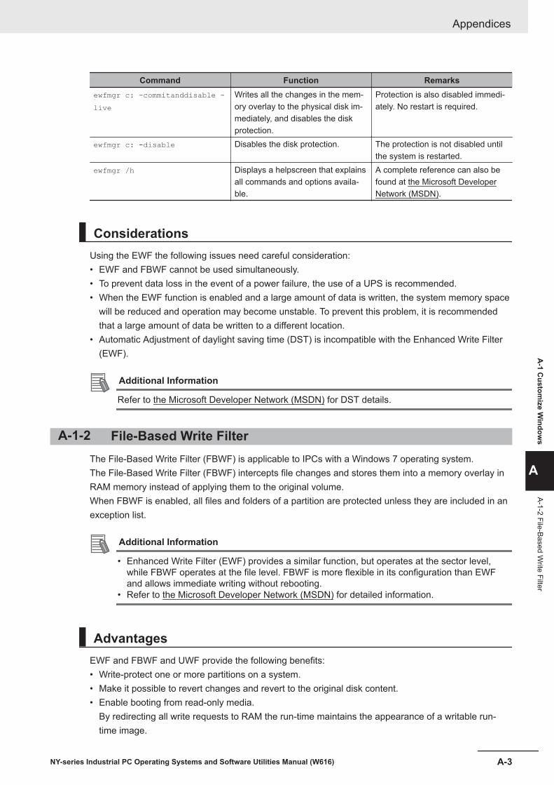
Command Function Remarksewfmgr c: -commitanddisable -live
Writes all the changes in the mem-ory overlay to the physical disk im-mediately, and disables the diskprotection.
Protection is also disabled immedi-ately. No restart is required.
ewfmgr c: -disable Disables the disk protection. The protection is not disabled untilthe system is restarted.
ewfmgr /h Displays a helpscreen that explainsall commands and options availa-ble.
A complete reference can also befound at the Microsoft DeveloperNetwork (MSDN).
ConsiderationsUsing the EWF the following issues need careful consideration:• EWF and FBWF cannot be used simultaneously.• To prevent data loss in the event of a power failure, the use of a UPS is recommended.• When the EWF function is enabled and a large amount of data is written, the system memory space
will be reduced and operation may become unstable. To prevent this problem, it is recommendedthat a large amount of data be written to a different location.
• Automatic Adjustment of daylight saving time (DST) is incompatible with the Enhanced Write Filter(EWF).
Additional Information
Refer to the Microsoft Developer Network (MSDN) for DST details.
A-1-2 File-Based Write FilterThe File-Based Write Filter (FBWF) is applicable to IPCs with a Windows 7 operating system.The File-Based Write Filter (FBWF) intercepts file changes and stores them into a memory overlay inRAM memory instead of applying them to the original volume.When FBWF is enabled, all files and folders of a partition are protected unless they are included in anexception list.
Additional Information
• Enhanced Write Filter (EWF) provides a similar function, but operates at the sector level,while FBWF operates at the file level. FBWF is more flexible in its configuration than EWFand allows immediate writing without rebooting.
• Refer to the Microsoft Developer Network (MSDN) for detailed information.
AdvantagesEWF and FBWF and UWF provide the following benefits:• Write-protect one or more partitions on a system.• Make it possible to revert changes and revert to the original disk content.• Enable booting from read-only media.
By redirecting all write requests to RAM the run-time maintains the appearance of a writable run-time image.
Appendices
A-3NY-series Industrial PC Operating Systems and Software Utilities Manual (W616)
A-1 C
ustomize W
indows
A
A-1-2 File-Based Write Filter

• Improve the file system performance when using relatively slow storage.• Minimize write actions to the disk.
For example, minimize write access to flash memory. Write cycles on flash memory are limited fortechnical reasons.
UsageFBWF is included in the Windows Embedded Standard 7 image and disabled by default. The configu-ration of this component can be defined with the command line tool FBWFMGR.EXE.To run to FBWF Manager, open the Command Prompt with Administrator rights.
Command Function Remarksfbwfmgr Shows an overview with current
status.---
fbwfmgr /displayconfig Shows current configuration. ---
fbwfmgr /enable Enables the write filter. The protection is not effective untilthe system is restarted.
fbwfmgr /addvolume c: Adds a volume to the protected vol-ume list.
That volume will be protected afterthe next restart.
fbwfmgr /commit c: \Test.txt Writes the changes to the protectedfile/folder.
---
fbwfmgr /addexclusion C:\Test.txt
Adds a write-through path to theexclusion list (file/folder).
The exclusion is active after thenext restart.
fbwfmgr /removeexclusion C:\Test.txt
Removes the write-through pathfrom the exclusion list (file/folder).
The exclusion is removed after thenext restart.
fbwfmgr /h Displays a helpscreen that explainsall commands and options availa-ble.
A complete reference can also befound at the Microsoft DeveloperNetwork (MSDN).
Additional Information
When specifying a file name, notice the space between drive name (c:) and file path (\Test.txt).
ConsiderationsUsing the FBWF the following issues need careful consideration:• EWF and FBWF cannot be used simultaneously.• FBWF can only protect formatted volumes. Do not move files between protected and unprotected
volumes.• When the FBWF function is enabled and a large amount of data is written, the system memory
space will be reduced and operation may become unstable. To prevent this problem, it is recom-mended that a large amount of data be written to a different location.
• FBWF supports only NTFS and FAT32 file systems.• Automatic Adjustment of daylight saving time (DST) is incompatible with the File-Based Write Filter
(FBWF).
Additional Information
Refer to the Microsoft Developer Network (MSDN) for DST details.
Appendices
A-4 NY-series Industrial PC Operating Systems and Software Utilities Manual (W616)
A-1-3 Unified Write FilterThe Unified Write Filter (UWF) is applicable to IPCs with a Windows 10 operating system.The UWF intercepts disk changes and stores them into a memory overlay in RAM memory instead ofapplying them to the original volume.
Additional Information
• Refer to Advantages on page A-2 for details.• Refer to Considerations on page A-5 for details.• Refer to the Microsoft Developer Network (MSDN) for details.
AdvantagesEWF and FBWF and UWF provide the following benefits:• Write-protect one or more partitions on a system.• Make it possible to revert changes and revert to the original disk content.• Enable booting from read-only media.
By redirecting all write requests to RAM the run-time maintains the appearance of a writable run-time image.
• Improve the file system performance when using relatively slow storage.• Minimize write actions to the disk.
For example, minimize write access to flash memory. Write cycles on flash memory are limited fortechnical reasons.
ConsiderationsWhen using the Unified Write Filter (UWF) all disk changes are stored into a memory overlay in RAMmemory instead of applying them to the original volume. This also applies to the installation of soft-ware or changing parameters. For software changes, like Windows updates or system parameterchanges, it is required to disable the UWF, install the software and then enable the UWF again.
Using the UWF the following issues need careful consideration:• To prevent data loss in the event of a power failure, the use of a UPS is recommended.• When the UWF function is enabled and a large amount of data is written, the system memory space
will be reduced and operation may become unstable. To prevent this problem, it is recommendedthat a large amount of data be written to a different location.
• Automatic Adjustment of daylight saving time (DST) is incompatible with the UWF enabled.
ConfigurationThe Unified Write Filter (UWF) is included in the Windows 10 image.The UWF is default disabled for an Industrial PC.The configuration of this component can be defined with the command line tool uwfmgr.EXE.
To run the UWF Manager, open the Command Prompt with Administrator rights.
Appendices
A-5NY-series Industrial PC Operating Systems and Software Utilities Manual (W616)
A-1 C
ustomize W
indows
A
A-1-3 Unified W
rite Filter
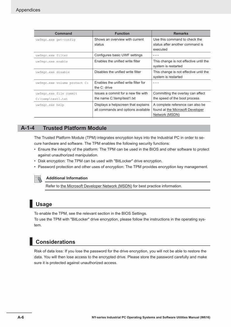
Command Function Remarksuwfmgr.exe get-config Shows an overview with current
statusUse this command to check thestatus after another command isexecuted
uwfmgr.exe filter Configures basic UWF settings - - -
uwfmgr.exe enable Enables the unified write filter This change is not effective until thesystem is restarted
uwfmgr.exe disable Disables the unified write filter This change is not effective until thesystem is restarted
uwfmgr.exe volume protect C: Enables the unified write filter forthe C: drive
- - -
uwfmgr.exe file commitC:\temp\test1.txt
Issues a commit for a new file withthe name C:\temp\test1.txt
Committing the overlay can affectthe speed of the boot process
uwfmgr.exe help Displays a helpscreen that explainsall commands and options available
A complete reference can also befound at the Microsoft DeveloperNetwork (MSDN)
A-1-4 Trusted Platform ModuleThe Trusted Platform Module (TPM) integrates encryption keys into the Industrial PC in order to se-cure hardware and software. The TPM enables the following security functions:• Ensure the integrity of the platform: The TPM can be used in the BIOS and other software to protect
against unauthorized manipulation.• Disk encryption: The TPM can be used with "BitLocker" drive encryption.• Password protection and other uses of encryption: The TPM provides encryption key management.
Additional Information
Refer to the Microsoft Developer Network (MSDN) for best practice information.
UsageTo enable the TPM, see the relevant section in the BIOS Settings.To use the TPM with "BitLocker" drive encryption, please follow the instructions in the operating sys-tem.
ConsiderationsRisk of data loss: If you lose the password for the drive encryption, you will not be able to restore thedata. You will then lose access to the encrypted drive. Please store the password carefully and makesure it is protected against unauthorized access.
Appendices
A-6 NY-series Industrial PC Operating Systems and Software Utilities Manual (W616)

IIndex
I-1NY-series Industrial PC Operating Systems and Software Utilities Manual (W616)
I

IndexA
Anti-virus software ............................................................ 5-3
B
Backup ........................................................... 3-23, 7-3, 7-12Blue screen .....................................................................7-32Browser ............................................................................ 5-2
C
Configuration ............................................................. 1-5, 1-7Corrective maintenance ..................................................7-19
D
DriveInstall in Windows ....................................................... 7-28
Drivers .............................................................................. 5-4
E
Enhanced Write Filter (EWF) ........................................... A-2Event viewer.................................................................... 7-29
Filter events ................................................................ 7-30
F
File-Based Write Filter (FBWF) ........................................ A-3Firewall ............................................................................. 5-3
I
Industrial Monitor Brightness Utility ................................ 3-20Industrial Monitor Utility .................................................. 3-13Industrial PC Support Utility ..............................................3-6
Product information .......................................................3-7RAID ............................................................................. 3-9System status ............................................................... 3-8
Industrial PC Tray Utility ................................................. 3-31Installation....................................................................... 3-39
L
Languages ........................................................................4-4Logging
Event viewer ............................................................... 7-29Messages ................................................. 3-12, 3-19, 3-22
Low on memory .............................................................. 7-31
M
MessagesError ............................................................................ 7-19Product ..........................................................................6-2Warning .......................................................................7-19
Windows ....................................................................... 6-3Model-ID ....................................................................1-5, 1-7
O
Operating system ............................................................. 4-3Windows........................................................................ 3-3
P
Power Attendant Lite Utility ............................................ 3-35Preventive maintenance ................................................... 7-2Product ...................................................................... 1-5, 1-7
R
RAID ............................................................................... 7-37Recover ............................................................................ 7-3Repair ......................................................................7-3, 7-20Rescue Disk Creator
Installation ...................................................................3-26Rescue Disk Utility ..........................................................3-23Rescue Disk ..................................................................... 7-7
Backup .......................................................................... 7-5Restore ....................................................................... 7-21
Restore ........................................ 3-23, 7-3, 7-20, 7-23, 7-27System repair ..............................................................7-26
S
SoftwareInstall .............................................................................5-4Update .......................................................................... 7-2
Storage devicesStatus...........................................................................7-15
System API .....................................................................3-39
T
Touchscreen ................................................................... 7-35Blocked ....................................................................... 7-35Calibrate ......................................................................7-34
Trusted Platform Module (TPM) .......................................A-6
U
Unified Write Filter (UWF) ................................................ A-5
W
Windows recovery drive ................................................. 7-10Windows system repair disk ............................................. 7-8Windows
Customize .....................................................................A-2
Index
I-2 NY-series Industrial PC Operating Systems and Software Utilities Manual (W616)


Authorized Distributor:
In the interest of product improvement, specifications are subject to change without notice.
Cat. No. W616-E2-04 0921
© OMRON Corporation 2019-2021 All Rights Reserved.
OMRON Corporation Industrial Automation Company
OMRON ELECTRONICS LLC2895 Greenspoint Parkway, Suite 200 Hoffman Estates, IL 60169 U.S.A.Tel: (1) 847-843-7900/Fax: (1) 847-843-7787
Regional Headquarters
OMRON EUROPE B.V.Wegalaan 67-69, 2132 JD HoofddorpThe NetherlandsTel: (31)2356-81-300/Fax: (31)2356-81-388
Contact: www.ia.omron.com
Kyoto, JAPAN
OMRON ASIA PACIFIC PTE. LTD.No. 438A Alexandra Road # 05-05/08 (Lobby 2), Alexandra Technopark, Singapore 119967Tel: (65) 6835-3011/Fax: (65) 6835-2711
OMRON (CHINA) CO., LTD.Room 2211, Bank of China Tower, 200 Yin Cheng Zhong Road, PuDong New Area, Shanghai, 200120, ChinaTel: (86) 21-5037-2222/Fax: (86) 21-5037-2200