o of res s dep nt in a -...
TRANSCRIPT
Oa(S
FrSé PFu20B CDScSc
Ththe
Optimizan EmeELDS)
Software A
rédéric Therébastien Pa
repared by: ujitsu Consu000, boulevaureau 300, Q
ontract Numocument Cocientific Authcientific Auth
he scientific or e contents do n
D
zation ergenc) Architectur
rrien quet
ulting (Canadard LebourgQuébec (Qu
mber: W7701ontrol Numbehority: Dr. Abhority Suppo
technical validnot necessarily
Defence
D
of Rescy Log
re Descrip
da) Inc. neuf ébec) G2K 0
1-5-3182, Taer: JCDS-CTbdeslem Boort: Mr. Jean
ity of this Conty have the appr
e R&DCo
DRDC ValDe
sourceistics
ption (SAD
0B8
ask AuthorizaTB-242-0374ukhtouta
n Berger, 418
tract Report is roval or endors
Canadontract Relcartier CRcember 2
es DepDecisi
D)
ation 39 (TA4
8-844-4000
entirely the ressement of Defe
da – VeportR 2011-622010
ploymeon Su
A39)
x 4645
sponsibility of tence R&D Cana
alcarti
23
ent in pport
the Contractor ada.
ier
Co
and
opy No:
ISSUE DATE: September 20, 2010
Software Architecture Description (SAD) Document control number: JCDS-CTB-242-0374
PAGE 1 OF 36
OPTIMIZATION OF RESOURCES DEPLOYMENT IN AN EMERGENCY LOGISTICS DECISION SUPPORT (ELDS)
SOFTWARE ARCHITECTURE DESCRIPTION (SAD)
Document control number: JCDS-CTB-242-0374
Version 2.0
This work was performed under contract to the
DEPARTMENT OF NATIONAL DEFENCE
Contract Number: W7701-5-3182, Task Authorization 39 (TA39)
DRDC Scientific Authority: Dr Abdeslem Boukhtouta
DRDC Scientific Authority Support: Mr. Jean Berger
And prepared by
Fujitsu Consulting (Canada) Inc. 2000, Boulevard Lebourgneuf
Bureau 300, Québec (Québec) G2K 0B8
The scientific or technical validity of this Contract Report is entirely the responsibility of the Contractor and the contents do not necessarily have the approval or endorsement of Defence R&D Canada.

ISSUE DATE: September 20, 2010
JCDS-CTB-TA39-242-ELDS SAD-v2.0.doc2
PAGE 2 OF 36
History Version Description Author Date
0.1 Initial Draft Sébastien Paquet May 1, 2009 0.2 Description of some technical views. Frédéric Therrien May 20, 2009 0.3 Restructure of the document and completion
of the design. Sébastien Paquet July 17, 2009
0.4 Internal Review Frédéric Therrien August 31, 2009 1.0 First complete version Sébastien Paquet September 01, 2009 1.1 First review for release 2.0 Frédéric Therrien July 9, 2010 1.2 Internal review for release 2.0 Sébastien Paquet September 20, 2010
© Her Majesty the Queen as represented by the Minister of National Defence, 2010
ISSUE DATE: September 20, 2010
JCDS-CTB-TA39-242-ELDS SAD-v2.0.doc2
PAGE 3 OF 36
Contents 1. SCOPE ................................................................................................................................................ 6
1.1 IDENTIFICATION ........................................................................................................................... 6 1.2 DOCUMENT OVERVIEW ................................................................................................................ 6 1.3 CONTEXT ..................................................................................................................................... 6 1.4 REFERENCES ................................................................................................................................ 7 1.5 RELATIONSHIP WITH OTHER DOCUMENTS .................................................................................... 7 1.6 NOTATION FOR DESCRIPTION ....................................................................................................... 7
2. SYSTEM OVERVIEW AND IDENTIFICATION ......................................................................... 8 2.1 DEPLOYMENT OPTIONS .............................................................................................................. 10
2.1.1 Centralized – One User ........................................................................................................ 10 2.1.2 Centralized – Multi Users ..................................................................................................... 10 2.1.3 Decentralized ........................................................................................................................ 12 2.1.4 Discussion about Deployments ............................................................................................. 12
3. ELDS ARCHITECTURAL DESIGN ............................................................................................ 14 3.1 SOFTWARE ARCHITECTURE GENERAL DESCRIPTION ................................................................. 14 3.2 SOFTWARE COMPONENTS DEFINITION ....................................................................................... 17
3.2.1 Presentation .......................................................................................................................... 17 3.2.2 Services ................................................................................................................................. 20 3.2.3 Decision Support Algorithms ................................................................................................ 23 3.2.4 Data Access .......................................................................................................................... 23 3.2.5 Repository ............................................................................................................................. 26
3.3 EXTERNAL COMPONENTS DEFINITION ....................................................................................... 26 3.3.1 Google Maps API ................................................................................................................. 27 3.3.2 MapServer ............................................................................................................................ 27
3.4 IDENTIFICATION OF SOFTWARE REQUIREMENTS ALLOCATED TO EACH SOFTWARE COMPONENT 27 3.5 SOFTWARE COMPONENTS CONCEPT OF EXECUTION .................................................................. 27
3.5.1 Get ELDS Layers .................................................................................................................. 27 3.5.2 Get Base Map ....................................................................................................................... 28 3.5.3 Calculate Paths ..................................................................................................................... 29 3.5.4 Call Localisation Algorithm ................................................................................................. 30
ISSUE DATE: September 20, 2010
JCDS-CTB-TA39-242-ELDS SAD-v2.0.doc2
PAGE 4 OF 36
3.5.5 Call Routing Algorithm......................................................................................................... 31 3.5.6 Build Distance and Time Matrix ........................................................................................... 33
3.6 RESOURCE LIMITATIONS AND THE STRATEGY FOR MANAGING EACH RESOURCE AND ITS LIMITATIONS ............................................................................................................................................ 33
4. RATIONALE FOR SOFTWARE ARCHITECTURE AND COMPONENT DEFINITION DECISIONS ................................................................................................................................................ 35 5. GLOSSARY ..................................................................................................................................... 36
ISSUE DATE: September 20, 2010
JCDS-CTB-TA39-242-ELDS SAD-v2.0.doc2
PAGE 5 OF 36
List of Figures Figure 1: System Overview Use Case ................................................................................ 9
Figure 2: Centralized – One User Deployment Diagram .................................................. 10
Figure 3: Centralised – Multi Users Deployment Diagram .............................................. 11
Figure 4: Decentralized Deployment Diagram ................................................................. 12
Figure 5: ELDS High Level Component View ................................................................. 14
Figure 6: ELDS Model-View-Controller architecture ...................................................... 16
Figure 7: ELDS Screen Shot ............................................................................................. 17
Figure 8: Generic Controller Class Diagram .................................................................... 20
Figure 9: ELDS Entities (1 of 2) ....................................................................................... 24
Figure 10: ELDS Entities (2 of 2) ..................................................................................... 25
Figure 11: ELDS Repository ............................................................................................ 26
Figure 12: External Components View ............................................................................. 27
Figure 13: Get ELDS Layers Sequence Diagram ............................................................. 28
Figure 14: Get Base Map Sequence Diagram ................................................................... 29
Figure 15: Calculate Paths Sequence Diagram ................................................................. 30
Figure 16: Call Localisation Algorithms Sequence Diagram ........................................... 31
Figure 17: Call Routing Algorithms Sequence Diagram .................................................. 32
Figure 18: Build Distance and Time Matrix Sequence Diagram ...................................... 33
ISSUE DATE: September 20, 2010
JCDS-CTB-TA39-242-ELDS SAD-v2.0.doc2
PAGE 6 OF 36
1. Scope This Software Architecture Description (SAD) describes the top-level system architecture of the Emergency Logistic Decision Support (ELDS) prototype. It presents the ELDS purpose, constraints, design decisions and rationale. It partitions the system into design entities and describes the important properties and relationships among these entities. It identifies high-level items of software (including database and user interface) and manual operations, and their interfaces.
1.1 Identification This document, referred with the Document control number: JCDS-CTB-242-0374, is a Software Architecture Description document that has been produced following [IEEE STD 1471-2000] in the context of a Research and Development (R&D) project led by Defence Research and Development Canada at Valcartier (DRDC-Valcartier) named “Optimization of resources deployment in an Emergency Logistics Decision Support (ELDS)”.
1.2 Document Overview This document presents the architecture of the Emergency Logistics Decision Support (ELDS) prototype.
• Section 2 presents an overview of the ELDS system and also describes some deployment options.
• Section 3 presents the ELDS architectural design. It describes each ELDS components and presents some sequence diagrams which document the interactions between the components.
• Section 4 presents the rationale for some architectural decisions.
1.3 Context DRDC-Valcartier and Fujitsu are both involved in a complementary research project, called PROMPT in this document, with Laval University, which considers the optimization of the deployment of military resources in a logistics network in the case of emergency operations.
The problem that will be solved in the PROMPT project deals with the coordination of commodity transportation from supply centers to distribution centers in the affected areas and the transport of wounded people from those areas to the emergency medical centers, etc. The problem deals also with issues related to the operations management and supply chain management in the case of emergency. A typical objective can be to minimize the time for the provision of prioritized commodities to survivors and health care services to injured people, where different types of vehicles are utilized to serve the transportation needs.
Logistics and the coordination of its related operations became the lifeline in such case. Different organizations (Military Forces, Red Cross, Disaster Relief Organizations, NGOs…) can be involved in the rescues effort. In this case, an emergency-logistics planning will extremely help to improve the rescue and recovery situation.
The complexity of the challenges facing the decision makers demands innovative means and technologies. The main research thread of the PROMPT project will be addressed within Laval University in collaboration with DRDC-Valcartier and FUJITSU.
ISSUE DATE: September 20, 2010
JCDS-CTB-TA39-242-ELDS SAD-v2.0.doc2
PAGE 7 OF 36
The development thread will be addressed via the current TA39 project. Precisely, this work aim at developing decision aids (i.e. user interfaces for the visualisation of proposed plans, the modification and approval of these plans and the sharing of information (both decisions and situation awareness information), etc.) and simulation capabilities to integrate the developed procedures/algorithms/scenarios, etc. addressed in the PROMPT Project.
1.4 References [IEEE STD 1471-2000] IEEE Recommended Practice for Architectural Description of Software-Intensive Systems
1.5 Relationship with other documents None
1.6 Notation for Description In this document, the UML notation is used.

ISSUE DATE: September 20, 2010
JCDS-CTB-TA39-242-ELDS SAD-v2.0.doc2 PAGE 8 OF 36
2. System Overview and Identification The objective of the Emergency Logistic Decision Support (ELDS) prototype is to provide decision support for the localisation of humanitarian aid centers (CAH) and for the optimization of resources deployment when managing emergency situations. Figure 1 presents the System Overview Use Case which illustrates the main functions of the ELDS prototype.
The ELDS is a prototype in which the background information is supposed to be available. In other words, the assumption is that the information about the population, the area, the level of damage, the level of injury, etc is already available with some degree of precision at the start of the system. In operation, these data will need to be inputted in the system.
Another set of functions are the geospatial utilities, which includes all geospatial functions allowing to visualize geo-referenced entities on the map, to manipulate them and to calculate geospatial functions such as distance and inclusion in an area. For example of geospatial functionality, it is possible to calculate paths between geographical locations. Users can thus visualize the generated paths and adjust them if they do not like a path or if a path is impossible, because of a road blocked for instance. Moreover, the Google Maps API is used for some geospatial functions such as finding the path between two locations.
The next major block of functions is to provide decision aid for the two problems managed by the ELDS prototype: the localisation of CAH and the vehicle routing problem. For both problems, the calculations are done in background and the user can visualize the proposed solutions. After evaluating the proposed solutions, the user can modify or approve a solution. The ELDS prototype thus provides all the user interfaces necessary for users to visualize the proposed solutions and to modify them in order to best fit their needs.

ISSUE DATE: September 20, 2010
JCDS-CTB-TA39-242-ELDS SAD-v2.0.doc2
PAGE 9 OF 36
uc System Ov erv iew
ELDS
Input scenario data
Calculate the number and location of CAHs
Present the proposed CAHs deployments
Modify a proposed CAH deployment
Approv e a proposed CAH deployment
Calculate solutions for the v ehicle routing
problem
Present the proposed solutions for the vehicle
routing problem
Modify a proposed solution for the vehicle
routing problem
Approve a proposed solution for the vehicle
routing problem
Calculate paths between
geographical locations
Adjust paths between geographical locations
User
Administrator
Google Maps API
Decision Support Algorithms
«use»
«extend»
«extend»
«use»
«extend»
«extend»
«use»
«invokes»
Figure 1: System Overview Use Case

ISSUE DATE: September 20, 2010
JCDS-CTB-TA39-242-ELDS SAD-v2.0.doc2
PAGE 10 OF 36
2.1 Deployment Options There are three possible ways to deploy the ELDS prototype: centralized with one or many users and decentralized. These deployments impact the capabilities that must be supported by the ELDS prototype. The following subsections describe each deployment.
2.1.1 Centralized – One User In this deployment option, there is one ELDS server in each humanitarian aid center (CAH). Each server is unconnected to any other servers and thus each CAH are independent and have their own data about the situation. In this context, the coordination between aid centers can only be achieved via telephone or other human communications, but not at the system level.
In one CAH, many users can connect to the server, but the concurrency is not managed and thus users should not try to modify the same information. One way to implicitly manage the concurrency is to allow only one user to modify a set of data and only allow the other users to view the information.
deployment Centralized – One User
«execution environment»CAH
ELDS Serv er
ELDS Client (Web Browser)
Database
Map Serv er
Application Serv er
User
Figure 2: Centralized – One User Deployment Diagram
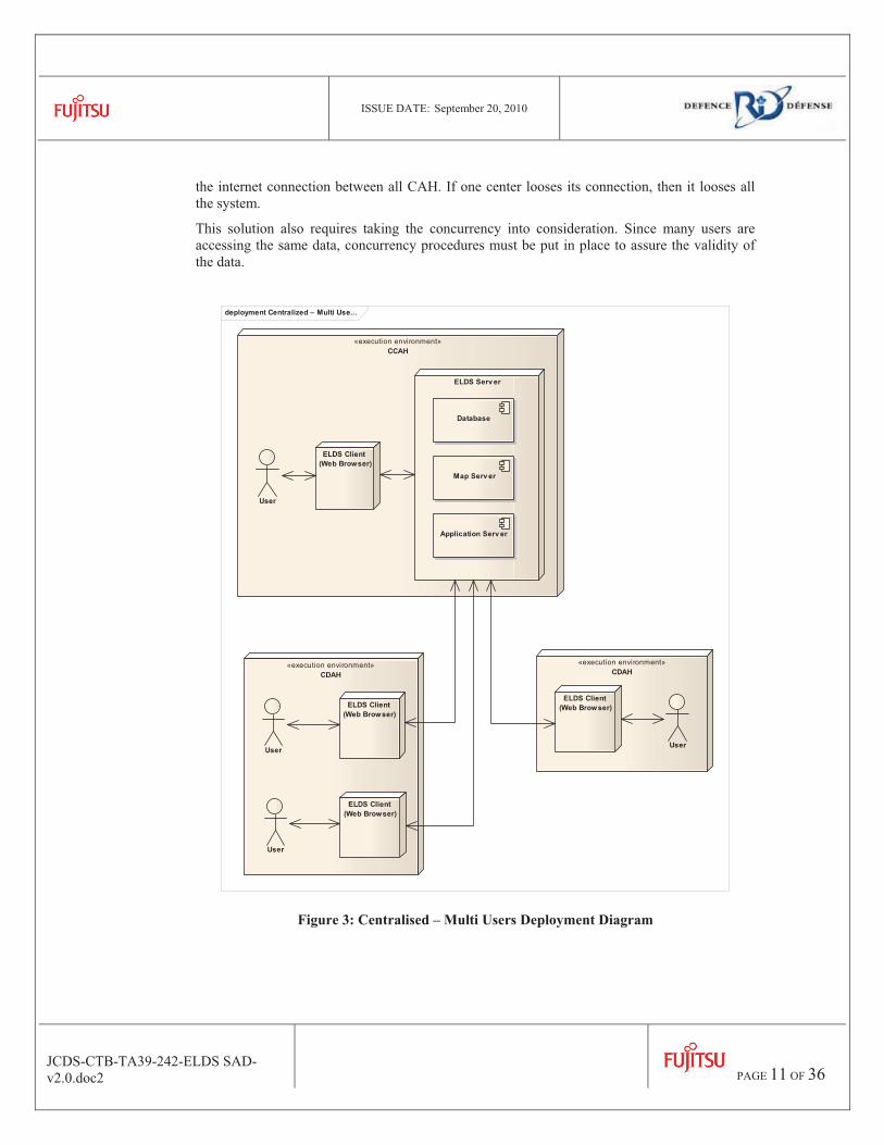
2.1.2 Centralized – Multi Users With this deployment option, there is only one server for the entire operation. This server can be situated anywhere, but for our example, we have put it in the coordination center (CCAH). In this situation, the all users access the same server using their client in a web browser.
Since all users access the same server, then all users in every center sees all the information. The sharing of information is thus improved. The drawback is that the system is now dependent on
ISSUE DATE: September 20, 2010
JCDS-CTB-TA39-242-ELDS SAD-v2.0.doc2
PAGE 11 OF 36
the internet connection between all CAH. If one center looses its connection, then it looses all the system.
This solution also requires taking the concurrency into consideration. Since many users are accessing the same data, concurrency procedures must be put in place to assure the validity of the data.
deployment Centralized – Multi Use...
«execution environment»CDAH
«execution environment»CDAH
«execution environment»CCAH
ELDS Serv er
ELDS Client (Web Browser)
Database
Map Serv er
User
Application Serv er
ELDS Client (Web Browser)
ELDS Client (Web Browser)
UserUser
ELDS Client (Web Browser)
User
Figure 3: Centralised – Multi Users Deployment Diagram

ISSUE DATE: September 20, 2010
JCDS-CTB-TA39-242-ELDS SAD-v2.0.doc2
PAGE 12 OF 36
2.1.3 Decentralized In the decentralized scenario, the servers are replicated in each CAH and users are accessing the server in their CAH. The servers are then synchronized together in order to propagate data and make sure all CAH have the same information about the emergency situation.
This deployment is more robust, because is a link is lost, the CAH can continue to work in a stand alone or degraded mode. When the connection is repaired, the servers can resynchronize in order to propagate the information and re-obtain a shared view of the emergency situation.
deployment Decentralized
«execution environment»CDAH
«execution environment»CDAH
«execution environment»CCAH
ELDS Serv er
ELDS Client (Web Browser) Database
Map Serv er
User
Application Serv er
ELDS Client (Web Browser) ELDS Client
(Web Browser)
UserUser
ELDS Client (Web Browser)
ELDS Client (Web Browser)
ELDS Client (Web Browser)
ELDS Serv er
Database
Map Serv er
Application Serv er
ELDS Serv er
Database
Map Server
Application Server
User
User User
SynchronisationSynchronisation
Synchronisation
Figure 4: Decentralized Deployment Diagram
2.1.4 Discussion about Deployments In the previous sections, three deployment options have been presented. For the problem of emergency management, the ideal deployment is the decentralized one because the

ISSUE DATE: September 20, 2010
JCDS-CTB-TA39-242-ELDS SAD-v2.0.doc2
PAGE 13 OF 36
infrastructure in emergency situation is often not reliable and thus each CAH should be autonomous. However, they still need to have a shared view of the situation which is accomplished by the servers’ synchronisation.
The decentralized deployment is also the most complex to develop and since the concurrency and synchronisations issues are not the focus of this R&D project, this solution will not be further explored. For the same reason, the Centralized Multi Users option will not be explored either.
Therefore, the solution that will be developed is the Centralized – One User option because it is the simplest one which will allow us to concentrate the efforts on the decision aid and algorithmic aspects. In other words, the first deployment option is sufficient to demonstrate what needs to be demonstrated in this R&D project.
ISSUE DATE: September 20, 2010
JCDS-CTB-TA39-242-ELDS SAD-v2.0.doc2
PAGE 14 OF 36
3. ELDS Architectural Design
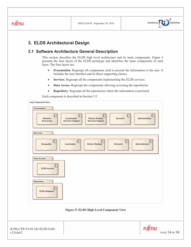
3.1 Software Architecture General Description This section describes the ELDS high level architecture and its main components. Figure 5 presents the four layers of the ELDS prototype and identifies the main components of each layer. The four layers are:
• Presentation. Regroups all components used to present the information to the user. It includes the user interface and its direct supporting classes.
• Services. Regroups all the components implementing the ELDS services.
• Data Access. Regroups the components allowing accessing the repositories.
• Repository. Regroups all the repositories where the information is persisted.
Each component is described in Section 3.2.
cmp Component View
Presentation
Serv ices
Data Access
Repository
Situation Awareness
Localisation Decision Support
AdministrationScenarioVehicle Routing Decision Support
ELDS Database
LocalisatonGeospatial Vehicle Routing Scenario Administration
ELDS Access
Figure 5: ELDS High Level Component View

ISSUE DATE: September 20, 2010
JCDS-CTB-TA39-242-ELDS SAD-v2.0.doc2
PAGE 15 OF 36
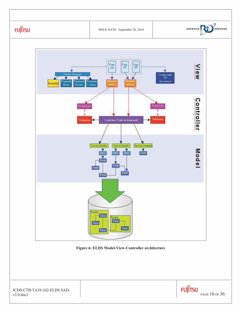
From another perspective, the ELDS prototype is structured using the Model-View-Controller pattern. In order to make some linkage with the component view, the ELDS Presentation layer contains the View, the ELDS Services layer contains the Controllers and the Data Access layer contains the Model. The ELDS Model-View-Controller architecture is depicted in the Figure 6.
The View section manages the display logic. This section can be separated in 2 sub-sections:
1- The first section is the user display component. This part contains everything that will be shown to the user. That includes tags, javascripts, fragments, html pages, etc.
2- In the second section, the logic needed to display the pages. That means forms that contain the values for input/output and the beans that contain all the actions to perform.
The controller section is the main section of all the architecture. This is where all the business logic is performed. For every process, you have a controller behind. The controller must perform all the validations (done by a validator but in the controller process) then, if all values are valid, the controller must retrieve/save/update/delete data, depending on the action chosen by the user. To perform the data access, the process must use all the classes defined in the model section.
The model section is responsible for the data access logic. This section contains 2 sub-sections:
1- The first one is the service section. This sub-section must be used for common services. For example, all the processing for the login is done in the sec_user service.
2- In the other section, you will find all the DAO (Data Access Object) and the entity. These entities represent all tables in the database. The DAO are the only classes that interact with the database. They do this interaction by using the entities.
The way all these sections can interact together is by the information defined in the following xml files: controleurAppContext.xml, modelAppContext.xml and vueAppContext.xml. In order you define: all controllers in the project, all common services, DAO and entity in the project and all beans. An important thing to understand is that the View section sees the model and controller, but the inverse is false. Same for the controller, it sees the model section, but the model doesn’t see the controller.
ISSUE DATE: September 20, 2010
JCDS-CTB-TA39-242-ELDS SAD-v2.0.doc2
PAGE 16 OF 36
Figure 6: ELDS Model-View-Controller architecture

ISSUE DATE: September 20, 2010
JCDS-CTB-TA39-242-ELDS SAD-v2.0.doc2
PAGE 17 OF 36
3.2 Software Components Definition The following subsections present the components of the ELDS prototype belonging to each layer.
3.2.1 Presentation The presentation layer includes all components presenting information to the users. This includes all the components of the user interface and all classes providing presentation services. As presented on Figure 5, the Presentation layer includes the following components:
• Situation Awareness
• Administration
• Decision Support
The ELDS Graphical User Interface (GUI) is based on the Dimensions software developed at Fujitsu (see Figure 7). It contains a left menu allowing accessing all ELDS tools. The center section is the working area containing ELDS forms and the map. The base map is provided by Google via the Google Maps API and the ELDS’s layers are provided by MapServer, which is connected to the ELDS database.
Figure 7: ELDS Screen Shot

ISSUE DATE: September 20, 2010
JCDS-CTB-TA39-242-ELDS SAD-v2.0.doc2
PAGE 18 OF 36
Situation Awareness
The situation awareness view is principally composed of a map presenting the information about the emergency situation. On this map, users can see the emergency zones, the location of the CAH, the location of service points and the blocked roads. The situation awareness view allows users to interact with the geo-referenced entities mapped on the Google base map. The map also offers all the basic Geographic Information System (GIS) functionalities such as zoom, layers showing and hiding, moving the map, etc. Moreover, users can have access to the entities metadata, such as the metadata of a CDAH.
The situation awareness allows all users to share a vision of the situation. However, for their specific needs, users can select or unselect layers of information to show or hide information on the map. For example, a user may remove the zoning information, if it is not useful to him.
Additionally, all organisations will be responsible for updating their layer representing their information. This layer will then be sharable between all organisations in order to support the collaboration between the organisations. For example, if the coordinator wants to see the status of the transport ministry, he will have the possibility to look at their layer and see their situation. This information can then be overlaid over another organisation layer in order to support the coordination effort and the planning process.
This view also provides complementary geospatial functions such as:
• Find. Users can enter a place name or an address and see the location of this entity on the map.
• Favourites. Users can save a GIS view and give it a name. Afterwards, users can browse their favourites list and select a favourite. This will place the GIS at the same place and with the same zoom level as when the favourite was saved.
• Query the map. A user can click at one place on the map and ask for an identification of this location. This will call the Google Maps API and show to the user a description of the closest entity found in the Google database. This can be used to get the address or the latitude and longitude of a location.
• Draw. Users can draw polygons on the map. This can be used to define emergency zones.
• Move entities. Users can move entities, such as CAH.
Furthermore, users can visualize the paths between all CAH and service points.
Decision Support
This view allows users to launch the process that will help them to find the best possible deployment of their resources. This view is composed of the following:
Script
This view allows the users to manually input the data of his situation. The input type is a series of sql insert.
Estimated Demand
This view allows the users to see what zone need which product(s) and in which quantity.
ISSUE DATE: September 20, 2010
JCDS-CTB-TA39-242-ELDS SAD-v2.0.doc2
PAGE 19 OF 36
Number of CAH
This view allows users to see the optimal number of CAH to open depending on the scenario data. This number is found by the decision support algorithms and it can be modified (increased or decreased) by the user if he thinks it is required to.
Localisation Decision Support
This view allows users to visualize, influence and adjust the propositions of the system regarding the localisation of the different CAH. This view will provide decision support for determining:
• The localisation of these centers.
The system will provide different solutions that will be presented with information about the criteria that were used to generate the solution. Users will then have the possibility to revise the options and choose the best one. If a solution needs some adjustments, the user will have the possibility to make them.
Furthermore, users will have the possibility to modify the parameters and start a new generation of solutions. This will allow users to test different what-if scenarios.
Selected Option
This view allows users to visualize the selected option in the previous step.
Resources Allocation
This view allows users to visualize the following:
� The number of humanitarian functions to offer for each center (functions include products delivery and services).
� The staffing and the number of resources (e.g. vehicles) for each center.
The user has the possibility to change the number of resources.
Vehicle Routing Decision Support
This view allows users to visualize, influence and adjust the propositions of the system regarding the vehicle routing between CAHs and service points. This view will provide decision support for:
• Determining the itinerary of the vehicles.
• Visualizing the stock at each CAH.
• Visualizing the location of each vehicle at CAH.
As for the localisation problem, the system will provide different solutions that will be presented with information about the criteria that were used to generate the solution. Users will then have the possibility to revise the options and choose the best one. If a solution needs some adjustments, the user will have the possibility to make them.
Furthermore, users will have the possibility to modify the parameters and start a new generation of solutions. This will allow users to test different what-if scenarios.
ISSUE DATE: September 20, 2010
JCDS-CTB-TA39-242-ELDS SAD-v2.0.doc2
PAGE 20 OF 36
Administration
The administration view allows managing the ELDS prototype and as such should only be accessible by ELDS administrators. They will have the possibility to create, modify and delete users, groups and organisations.
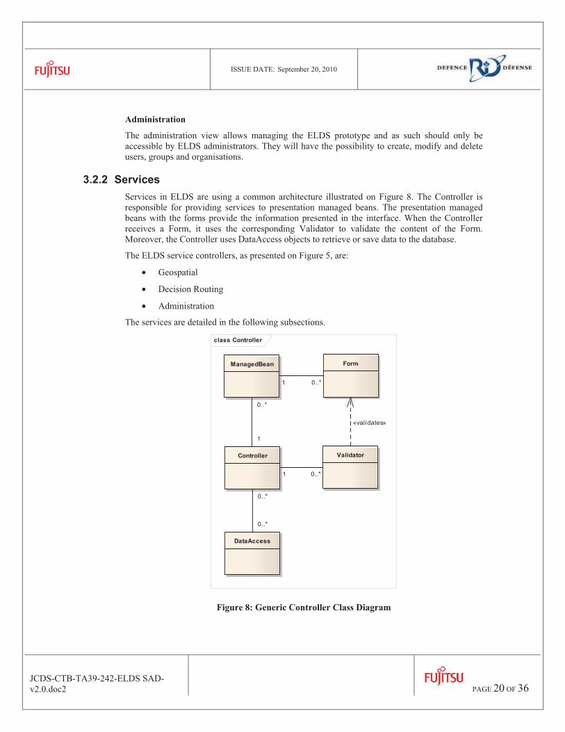
3.2.2 Services Services in ELDS are using a common architecture illustrated on Figure 8. The Controller is responsible for providing services to presentation managed beans. The presentation managed beans with the forms provide the information presented in the interface. When the Controller receives a Form, it uses the corresponding Validator to validate the content of the Form. Moreover, the Controller uses DataAccess objects to retrieve or save data to the database.
The ELDS service controllers, as presented on Figure 5, are:
• Geospatial
• Decision Routing
• Administration
The services are detailed in the following subsections.
class Controller
Controller Validator
FormManagedBean
DataAccess
1 0..*
0..*
1
1 0..*
«validates»
0..*
0..*
Figure 8: Generic Controller Class Diagram
ISSUE DATE: September 20, 2010
JCDS-CTB-TA39-242-ELDS SAD-v2.0.doc2
PAGE 21 OF 36
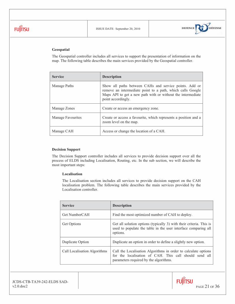
Geospatial
The Geospatial controller includes all services to support the presentation of information on the map. The following table describes the main services provided by the Geospatial controller.
Service Description
Manage Paths Show all paths between CAHs and service points. Add or remove an intermediate point to a path, which calls Google Maps API to get a new path with or without the intermediate point accordingly.
Manage Zones Create or access an emergency zone.
Manage Favourites Create or access a favourite, which represents a position and a zoom level on the map.
Manage CAH Access or change the location of a CAH.
Decision Support
The Decision Support controller includes all services to provide decision support over all the process of ELDS including Localisation, Routing, etc. In the sub section, we will describe the most important steps:
Localisation
The Localisation section includes all services to provide decision support on the CAH localisation problem. The following table describes the main services provided by the Localisation controller.
Service Description
Get NumberCAH Find the most optimized number of CAH to deploy.
Get Options Get all solution options (typically 3) with their criteria. This is used to populate the table in the user interface comparing all options.
Duplicate Option Duplicate an option in order to define a slightly new option.
Call Localisation Algorithms Call the Localisation Algorithms in order to calculate options for the localisation of CAH. This call should send all parameters required by the algorithms.
ISSUE DATE: September 20, 2010
JCDS-CTB-TA39-242-ELDS SAD-v2.0.doc2
PAGE 22 OF 36
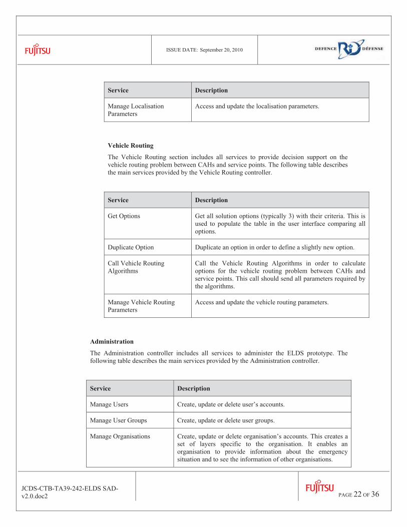
Service Description
Manage Localisation Parameters
Access and update the localisation parameters.
Vehicle Routing
The Vehicle Routing section includes all services to provide decision support on the vehicle routing problem between CAHs and service points. The following table describes the main services provided by the Vehicle Routing controller.
Service Description
Get Options Get all solution options (typically 3) with their criteria. This is used to populate the table in the user interface comparing all options.
Duplicate Option Duplicate an option in order to define a slightly new option.
Call Vehicle Routing Algorithms
Call the Vehicle Routing Algorithms in order to calculate options for the vehicle routing problem between CAHs and service points. This call should send all parameters required by the algorithms.
Manage Vehicle Routing Parameters
Access and update the vehicle routing parameters.
Administration
The Administration controller includes all services to administer the ELDS prototype. The following table describes the main services provided by the Administration controller.
Service Description
Manage Users Create, update or delete user’s accounts.
Manage User Groups Create, update or delete user groups.
Manage Organisations Create, update or delete organisation’s accounts. This creates a set of layers specific to the organisation. It enables an organisation to provide information about the emergency situation and to see the information of other organisations.
ISSUE DATE: September 20, 2010
JCDS-CTB-TA39-242-ELDS SAD-v2.0.doc2
PAGE 23 OF 36
3.2.3 Decision Support Algorithms The Decision Support algorithms will not be described here, since they will be described in the documentation and articles produced by Laval University.
For the ELDS prototype, the University algorithms are only specialised business services. They will be managed the same way as the other ELDS services. Therefore, they will have access to all the data in the database. The algorithms will be triggered by other ELDS services that will be used to manage users’ interactions.
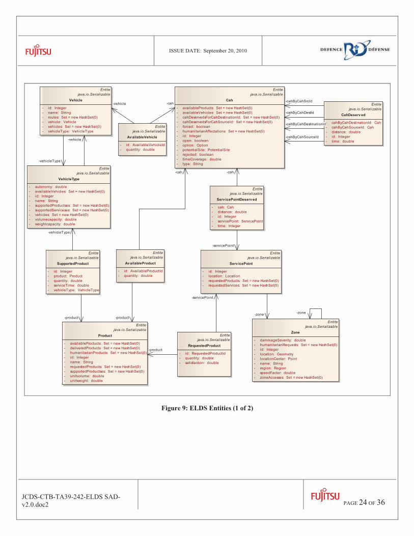
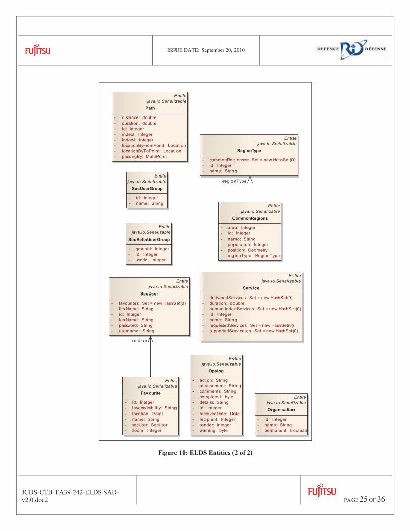
3.2.4 Data Access This layer includes all components providing an access to repositories. In ELDS, there is only one repository: the ELDS repository. Therefore, there is only one ELDS Data Access component which is divided in many entities and data access objects (DAO). The DAO are called by services in order to create, access, update and delete entities. The entities represent the model of the ELDS prototype and are persisted in the ELDS database. The entities are represented on Figure 9 and Figure 10.
ISSUE DATE: September 20, 2010
JCDS-CTB-TA39-242-ELDS SAD-v2.0.doc2
PAGE 24 OF 36
Entitejava.io.Serializable
Av ailableProduct
- id: AvailableProductId- quantity: double
Entitejava.io.Serializable
Av ailableVehicle
- id: AvailableVehicleId- quantity: double
Entitejava.io.Serial izable
Cah
- availableProducts: Set = new HashSet(0)- availableVehicles: Set = new HashSet(0)- cahDeservedsForCahDestinationId: Set = new HashSet(0)- cahDeservedsForCahSourceId: Set = new HashSet(0)- forced: boolean- humanitarianAffectations: Set = new HashSet(0)- id: Integer- open: boolean- option: Option- potentialSite: PotentialSite- rejected: boolean- timeCoverage: double- type: String
Entitejava.io.Serializable
CahDeserv ed
- cahByCahDestinationId: Cah- cahByCahSourceId: Cah- distance: double- id: Integer- time: double
Entitejava.io.Serial izable
Product
- availableProducts: Set = new HashSet(0)- deliveredProducts: Set = new HashSet(0)- humanitarianProducts: Set = new HashSet(0)- id: Integer- name: String- requestedProducts: Set = new HashSet(0)- supportedProductses: Set = new HashSet(0)- unitvolume: double- unitweight: double
Entitejava.io.Serializable
RequestedProduct
- id: RequestedProductId- quantity: double- satisfaction: double
Entitejava.io.Serializable
Serv icePoint
- id: Integer- location: Location- requestedProducts: Set = new HashSet(0)- requestedServices: Set = new HashSet(0)
Entitejava.io.Serializable
Serv icePointDeserv ed
- cah: Cah- distance: double- id: Integer- servicePoint: ServicePoint- time: Integer
Entitejava.io.Serial izable
SupportedProduct
- id: Integer- product: Product- quantity: double- serviceTime: double- vehicleType: VehicleType
Entitejava.io.Serial izable
Vehicle
- id: Integer- name: String- routes: Set = new HashSet(0)- vehicle: Vehicle- vehicles: Set = new HashSet(0)- vehicleType: VehicleType
Entitejava.io.Serializable
VehicleType
- autonomy: double- availableVehicles: Set = new HashSet(0)- id: Integer- name: String- supportedProductses: Set = new HashSet(0)- supportedServiceses: Set = new HashSet(0)- vehicles: Set = new HashSet(0)- volumecapacity: double- weightcapacity: double
Entitejava.io.Serializable
Zone
- dammageSeverity: double- humanitarianRequests: Set = new HashSet(0)- id: Integer- location: Geometry- locationCenter: Point- name: String- region: Region- speedFactor: double- zoneAccesses: Set = new HashSet(0)
-product
-product
-vehicle -cah
-cahByCahDestId
-cahByCahSrcId
-cahByCahDestinationId
-cahByCahSourceId
-cah
-zone
-servicePoint
-zone
-cah
-servicePoint
-product
-vehicleType
-vehicleType
-vehicle
Figure 9: ELDS Entities (1 of 2)
ISSUE DATE: September 20, 2010
JCDS-CTB-TA39-242-ELDS SAD-v2.0.doc2
PAGE 25 OF 36
Entitejava.io.Serializable
CommonRegions
- area: Integer- id: Integer- name: String- population: Integer- position: Geometry- regionType: RegionType
Entitejava.io.Serializable
Favourite
- id: Integer- layersVisibil ity: String- location: Point- name: String- secUser: SecUser- zoom: Integer
Entitejava.io.Serializable
Opslog
- action: String- attachement: String- comments: String- completed: byte- details: String- id: Integer- receivedDate: Date- recipient: Integer- sender: Integer- warning: byte
Entitejava.io.SerializableOrganisation
- id: Integer- name: String- permanent: boolean
Entitejava.io.Serializable
Path
- distance: double- duration: double- id: Integer- indexI: Integer- indexJ: Integer- locationByFromPoint: Location- locationByToPoint: Location- passingBy: MultiPoint
Entitejava.io.Serializable
RegionType
- commonRegionses: Set = new HashSet(0)- id: Integer- name: String
Entitejava.io.Serial izable
SecReltnUserGroup
- groupId: Integer- id: Integer- userId: Integer
Entitejava.io.Serializable
SecUser
- favourites: Set = new HashSet(0)- firstName: String- id: Integer- lastName: String- password: String- username: String
Entitejava.io.Serializable
SecUserGroup
- id: Integer- name: String
Entitejava.io.Serializable
Serv ice
- deliveredServices: Set = new HashSet(0)- duration: double- humanitarianServices: Set = new HashSet(0)- id: Integer- name: String- requestedServices: Set = new HashSet(0)- supportedServiceses: Set = new HashSet(0)
-secUser
-regionType
Figure 10: ELDS Entities (2 of 2)

ISSUE DATE: September 20, 2010
JCDS-CTB-TA39-242-ELDS SAD-v2.0.doc2
PAGE 26 OF 36
3.2.5 Repository The ELDS repository contains all the information persisted within the prototype. The repository is accessed via the ELDS Data Access objects and also directly by MapServer for accessing the geo-referenced entities. The repository model is presented on Figure 11, but it is too big to be easily readable in this document; therefore an image file containing the repository model is distributed with this document.
class DataModel V2
spatial_ref_sys
«column»*PK srid: integer auth_name: varchar(256) auth_srid: integer srtext: varchar(2048) proj4text: varchar(2048)
geometry_columns
«column»*PK f_table_catalog: varchar(256)*PK f_table_schema: varchar(256)*PK f_table_name: varchar(256)*PK f_geometry_column: varchar(256)* coord_dimension: integer* srid: integer* type: varchar(30)
serv ice
«column»*PK id: integer* name: varchar(50)* duration: numeric(25,20)
supported_serv ices
«column»*pfK service_id: integer*pfK type_id: integer* service_time: numeric(25,20)
v ehicle_type
«column»*PK id: integer* weightcapacity: numeric(25,20)* volumecapacity: numeric(25,20)* name: varchar(50) autonomy: numeric(25,20)
v ehicle
«column»*PK id: integer*FK type: integer name: varchar(50)
region
«column»*PK id: integer* name: varchar(50)* location: geometry
zone_access
«column»*PK potential_site_id: integer*pfK zone_id: integer* access_time: numeric(25,20)
zone
«column»*PK id: integer FK region_id: integer* name: varchar(50)* location: geometry* location_center: geometry* dammage_severi ty: numeric(25,20) speed_factor: numeric(25,20)
requested_product
«column»*pfK product_id: integer*pfK service_point_id: integer* quantity: numeric(25,20)* satisfaction: numeric(25,20)
requested_serv ice
«column»*PK id: integer*FK service_id: integer*FK service_point_id: integer* quanti ty: numeric(25,20)* satisfaction: numeric(25,20)
geospatial_object
«column»*PK id: integer* type: varchar(50)* name: varchar(50)* location: geometry description: varchar(250)
opslog
«column»*PK id: integer* received_date: timestamp without time zone* sender: integer* recipient: integer* detai ls: varchar(250) attachement: bytea* action: varchar(50)* warning: boolean completed: boolean comments: varchar(250)
organisation
«column»*PK id: integer* name: varchar(50)* permanent: boolean
sec_reltn_user_group
«column»*PK id: integer* user_id: integer* group_id: integer
sec_user_group
«column»*PK id: integer* name: varchar(50)
supported_serv ice
«column»*PK id: integer* service_id: integer* type_id: integer
parameter
«column»*PK id: integer* attribut: varchar(250)* value: varchar(250)
av ailable_role_option
«column»*pfK option_id: integer*pfK available_role_id: integer* active: boolean
humanitarian_request_option
«column»*pfK option_id: integer*pfK humanitarian_request_id: integer* satisfaction: numeric(25,20)
av ailable_humanitarian_function_option
«column»*pfK option_id: integer*pfK available_humanitarian_function_id: integer* active: boolean
available_role
«column»*PK id: integer*FK potential_si te_id: integer*FK role_id: integer* habili ty: numeric(25,20)* activation_time: numeric(25,20)* capacity: numeric(25,20)* max_capacity_extension: numeric(25,20)* capacity_adding_time: numeric(25,20)
role
«column»*PK id: integer* name: varchar(250)* description: varchar(250)
av ailable_humanitarian_function
«column»*PK id: integer*FK potential_site_id: integer*FK humanitarian_function_id: integer habi lity: numeric(25,20)* activation_time: numeric(25,20)* capacity: numeric(25,20)* max_capacity_extension: numeric(25,20)* capacity_adding_time: numeric(25,20)
av ailable_product
«column»*pfK cah_id: integer*pfK product_id: integer* quantity: numeric(25,20)
av ailable_serv ice
«column»*pfK cah_id: integer*pfK service_id: integer* quantity: numeric(25,20)
available_v ehicle
«column»*pfK cah_id: integer*pfK vehicle_type_id: integer* quanti ty: numeric(25,20)
option
«column»*PK id: integer* name: varchar(50)* selected: boolean* created_timestamp: timestamp without time zone* access_time: numeric(25,20)* coverage: numeric(25,20) comments: text
cah_deserv ed
«column»*PK id: integer*FK cah_source_id: integer*FK cah_destination_id: integer* distance: numeric(25,20)* time: numeric(25,20)
deliv ered_product
«column»*pfK route_id: integer*pfK location_id: integer*pfK product_id: integer* quantity: numeric(25,20)
deliv ered_serv ice
«column»*pfK route_id: integer*pfK location_id: integer*pfK service_id: integer
fav ourite
«column»*PK id: integer* name: varchar(50)* zoom: integer*FK created_user: integer location: geometry* layers_visibi li ty: varchar(250)
sec_user
«column»*PK id: integer* username: varchar(50)* last_name: varchar(50) fi rst_name: varchar(50)* password: varchar(500)
cah
«column»*PK id: integer* type: varchar(50) time_coverage: numeric(25,20)* open: boolean*FK potential_site_id: integer FK option_id: integer* forced: boolean* rejected: boolean
humanitarian_affectation
«column»*pfK humanitarian_request_id: integer*pfK cah_id: integer* proportions: numeric(25,20)
humanitarian_product
«column»*PK id: integer*FK product_id: integer*FK humanitarian_function_id: integer* proportion: numeric(25,20)
humanitarian_request
«column»*PK id: integer*FK zone_id: integer*FK humanitarian_function_id: integer* type: varchar(50)* quantity: numeric(25,20)
humanitarian_function
«column»*PK id: integer* name: varchar(250)* critical_coverage_time: numeric(25,20)* priori ty: integer* max_extension_service_time: numeric(25,20)
humanitarian_serv ice
«column»*PK id: integer*FK service_id: integer*FK humanitarian_function_id: integer* proportion: integer
path
«column»*PK id: integer*FK from_point: integer*FK to_point: integer passing_by: geometry* index_i: integer* index_j: integer* distance: numeric(25,20)* duration: numeric(25,20)
route_sequence
«column»*pfK location_id: integer*pfK route_id: integer* step: integer
route
«column»*PK id: integer* name: varchar(50)*FK start_location: integer*FK vehicule: integer* total_time: numeric(25,20)* total_distance: numeric(25,20)* risk: numeric(25,20)*FK route_option: integer
serv ice_point
«column»*PK id: integer*FK location_id: integer
location
«column»*PK id: integer* name: varchar(50)* address: varchar(125)* location: geometry
potential_site
«column»*PK id: integer*FK location: integer* starting_time: numeric(25,20)
site_v ehicle_type
«column»*pfK id_potential_site: integer*pfK id_vehicle_type: integer* charging_time: integer
product
«column»*PK id: integer* unitvolume: numeric(25,20)* unitweight: numeric(25,20)* name: varchar(50)
supported_products
«column»*pfK product_id: integer*pfK type_id: integer* quanti ty: numeric(10,2)* servicetime: numeric(10,2)
route_option
«column»*PK id: integer* name: varchar(250)* total_time: numeric(25,20)* total_distance: numeric(25,20)
Figure 11: ELDS Repository
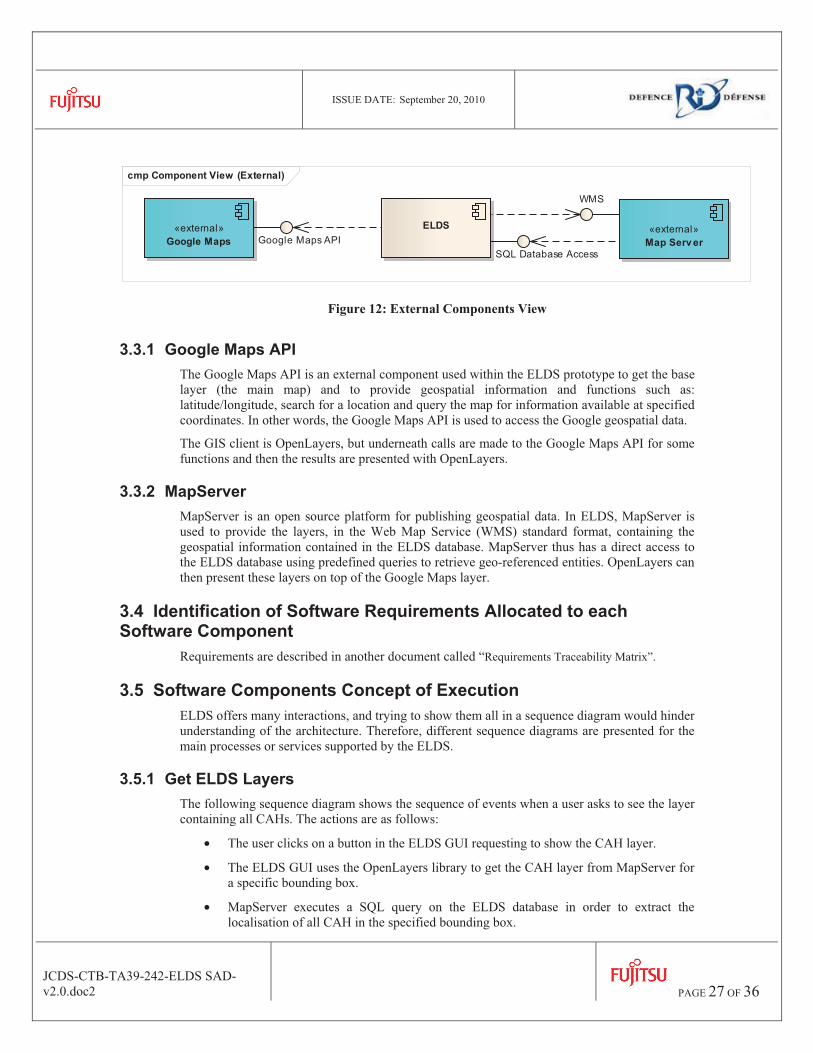
3.3 External Components Definition Figure 12 presents the ELDS external components, which are then described in the following sub-sections: Google Maps and Map Server.
ISSUE DATE: September 20, 2010
JCDS-CTB-TA39-242-ELDS SAD-v2.0.doc2
PAGE 27 OF 36
cmp Component View (External)
«external»Google Maps Google Maps API
«external»Map Serv er
WMS
ELDS
SQL Database Access
Figure 12: External Components View
3.3.1 Google Maps API The Google Maps API is an external component used within the ELDS prototype to get the base layer (the main map) and to provide geospatial information and functions such as: latitude/longitude, search for a location and query the map for information available at specified coordinates. In other words, the Google Maps API is used to access the Google geospatial data.
The GIS client is OpenLayers, but underneath calls are made to the Google Maps API for some functions and then the results are presented with OpenLayers.
3.3.2 MapServer MapServer is an open source platform for publishing geospatial data. In ELDS, MapServer is used to provide the layers, in the Web Map Service (WMS) standard format, containing the geospatial information contained in the ELDS database. MapServer thus has a direct access to the ELDS database using predefined queries to retrieve geo-referenced entities. OpenLayers can then present these layers on top of the Google Maps layer.
3.4 Identification of Software Requirements Allocated to each Software Component
Requirements are described in another document called “Requirements Traceability Matrix”.
3.5 Software Components Concept of Execution ELDS offers many interactions, and trying to show them all in a sequence diagram would hinder understanding of the architecture. Therefore, different sequence diagrams are presented for the main processes or services supported by the ELDS.
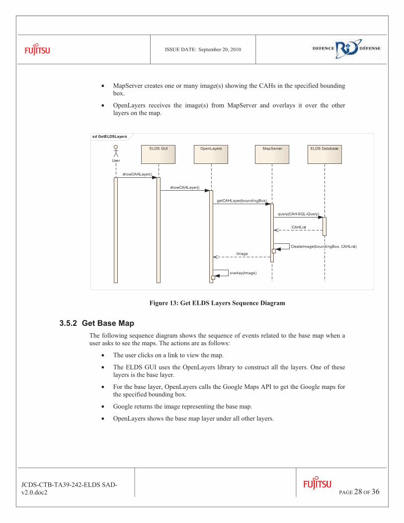
3.5.1 Get ELDS Layers The following sequence diagram shows the sequence of events when a user asks to see the layer containing all CAHs. The actions are as follows:
• The user clicks on a button in the ELDS GUI requesting to show the CAH layer.
• The ELDS GUI uses the OpenLayers library to get the CAH layer from MapServer for a specific bounding box.
• MapServer executes a SQL query on the ELDS database in order to extract the localisation of all CAH in the specified bounding box.
ISSUE DATE: September 20, 2010
JCDS-CTB-TA39-242-ELDS SAD-v2.0.doc2
PAGE 28 OF 36
• MapServer creates one or many image(s) showing the CAHs in the specified bounding box.
• OpenLayers receives the image(s) from MapServer and overlays it over the other layers on the map.
sd GetELDSLayers
User
ELDS GUI OpenLayers MapServer ELDS Database
showCAHLayer()
showCAHLayer()
getCAHLayer(boundingBox)
query(CAH-SQL-Query)
:CAHList
CreateImage(boundingBox, CAHList)
:Image
overlay(Image)
Figure 13: Get ELDS Layers Sequence Diagram
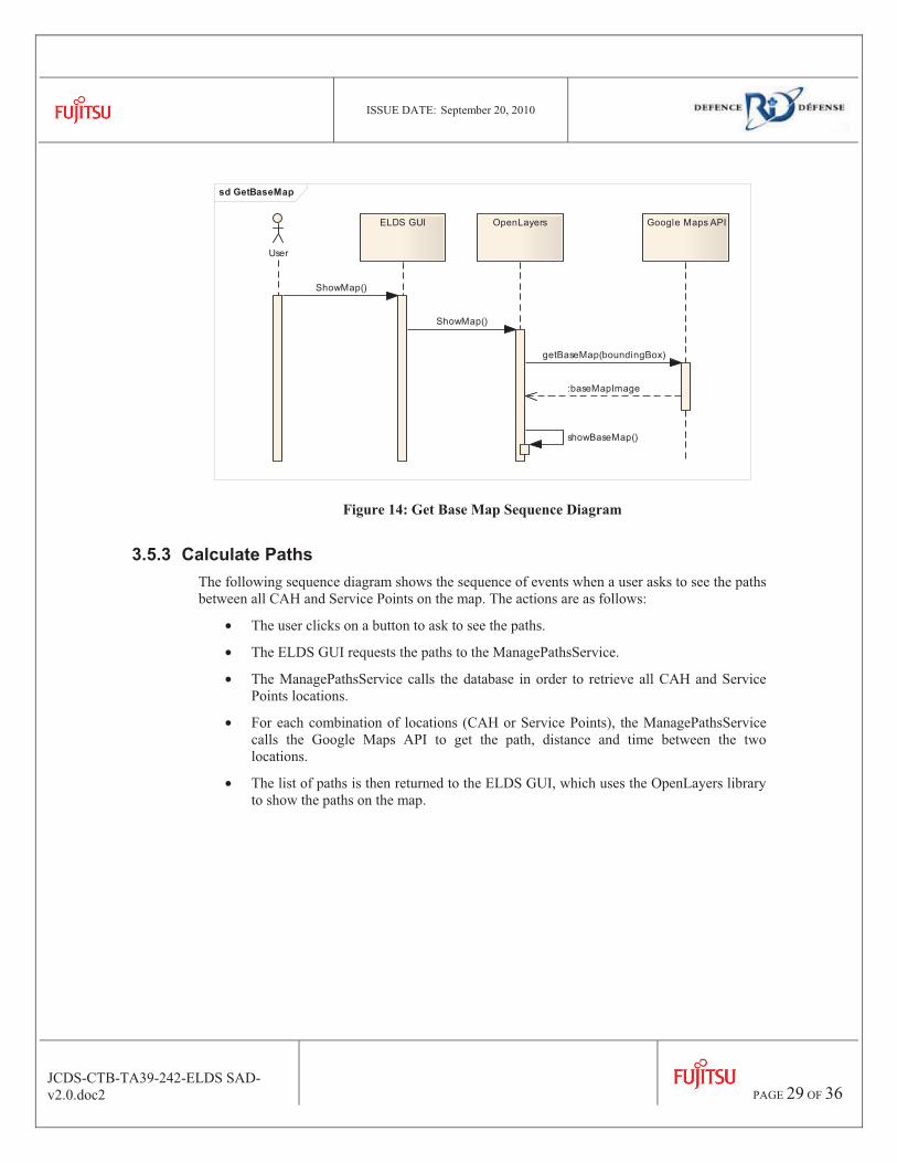
3.5.2 Get Base Map The following sequence diagram shows the sequence of events related to the base map when a user asks to see the maps. The actions are as follows:
• The user clicks on a link to view the map.
• The ELDS GUI uses the OpenLayers library to construct all the layers. One of these layers is the base layer.
• For the base layer, OpenLayers calls the Google Maps API to get the Google maps for the specified bounding box.
• Google returns the image representing the base map.
• OpenLayers shows the base map layer under all other layers.
ISSUE DATE: September 20, 2010
JCDS-CTB-TA39-242-ELDS SAD-v2.0.doc2
PAGE 29 OF 36
sd GetBaseMap
User
ELDS GUI OpenLayers Google Maps API
ShowMap()
ShowMap()
getBaseMap(boundingBox)
:baseMapImage
showBaseMap()
Figure 14: Get Base Map Sequence Diagram
3.5.3 Calculate Paths The following sequence diagram shows the sequence of events when a user asks to see the paths between all CAH and Service Points on the map. The actions are as follows:
• The user clicks on a button to ask to see the paths.
• The ELDS GUI requests the paths to the ManagePathsService.
• The ManagePathsService calls the database in order to retrieve all CAH and Service Points locations.
• For each combination of locations (CAH or Service Points), the ManagePathsService calls the Google Maps API to get the path, distance and time between the two locations.
• The list of paths is then returned to the ELDS GUI, which uses the OpenLayers library to show the paths on the map.

ISSUE DATE: September 20, 2010
JCDS-CTB-TA39-242-ELDS SAD-v2.0.doc2
PAGE 30 OF 36
sd CalculatePaths
User
ELDS GUI ManagePathsService ELDS Database Google Maps APIOpenLayers
loop GetAllPaths
[for all combinations of locations (CAHs and Service Points)]
viewPaths()
viewPaths()
getAllCAH()
:CAHList
getAllServicePoints()
:servicePointsList
getPath(location1, location2)
:path,distance,time
:pathsList
showPaths(pathsList)
showPathsOnMap()
Figure 15: Calculate Paths Sequence Diagram
3.5.4 Call Localisation Algorithm The following sequence diagram shows the sequence of events when a user asks to view the system propositions for the localisation of CAHs problem. The actions are as follows:
• The user clicks on a button to ask to view the system propositions for the localisation of CAHs problem.
• The ELDS GUI calls the ULaval service which calls the localisation algorithm component.
• The localisation algorithm component retrieves all the required data and passes it to CPlex.
• CPlex calculate the best solution based on the received criteria and return it to the localisation algorithm and the localisation algorithm returns it to the localisation service.
• The ULaval service repeats the 3 previous steps for every localisation algorithm it has.

ISSUE DATE: September 20, 2010
JCDS-CTB-TA39-242-ELDS SAD-v2.0.doc2
PAGE 31 OF 36
• The ULaval service returns a list of proposed options for the localisation problem.
• This list op options is passed to the ELDS GUI which shows a comparison table presenting all options criteria.
• When a user selects an option in the table, the corresponding layer is shown on the map, using the OpenLayers library.
Figure 16: Call Localisation Algorithms Sequence Diagram
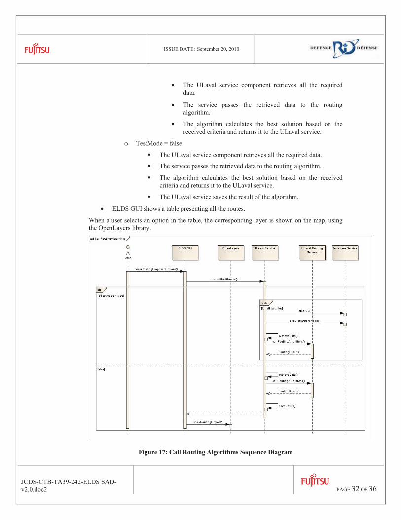
3.5.5 Call Routing Algorithm The following sequence diagram shows the sequence of events when a user asks to view the system propositions for the routing problem. The actions are as follows:
• The user clicks on a button to ask to view the system propositions for the routing problem.
• The ELDS GUI calls the ULaval service which calls the Routing algorithm component.
• Depending on if we are in a test mode or not the system change his actions:
o TestMode =true
� For every test file
• The ULaval service clear the database
• The service populate the database using data from a specified file
ISSUE DATE: September 20, 2010
JCDS-CTB-TA39-242-ELDS SAD-v2.0.doc2
PAGE 32 OF 36
• The ULaval service component retrieves all the required data.
• The service passes the retrieved data to the routing algorithm.
• The algorithm calculates the best solution based on the received criteria and returns it to the ULaval service.
o TestMode = false
� The ULaval service component retrieves all the required data.
� The service passes the retrieved data to the routing algorithm.
� The algorithm calculates the best solution based on the received criteria and returns it to the ULaval service.
� The ULaval service saves the result of the algorithm.
• ELDS GUI shows a table presenting all the routes.
When a user selects an option in the table, the corresponding layer is shown on the map, using the OpenLayers library.
Figure 17: Call Routing Algorithms Sequence Diagram
ISSUE DATE: September 20, 2010
JCDS-CTB-TA39-242-ELDS SAD-v2.0.doc2
PAGE 33 OF 36
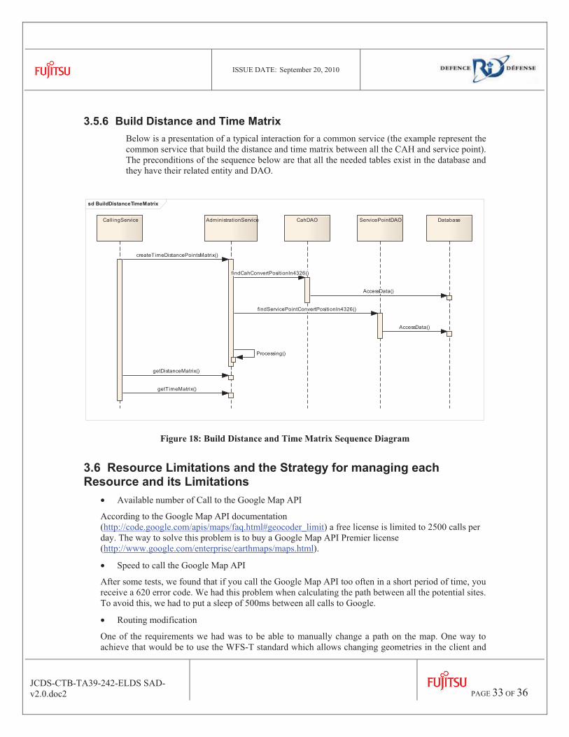
3.5.6 Build Distance and Time Matrix Below is a presentation of a typical interaction for a common service (the example represent the common service that build the distance and time matrix between all the CAH and service point). The preconditions of the sequence below are that all the needed tables exist in the database and they have their related entity and DAO.
sd BuildDistanceTimeMatrix
CallingService CahDAO DatabaseAdministrationService ServicePointDAO
createTimeDistancePointsMatrix()
findCahConvertPositionIn4326()
AccessData()
findServicePointConvertPositionIn4326()
AccessData()
Processing()
getDistanceMatrix()
getTimeMatrix()
Figure 18: Build Distance and Time Matrix Sequence Diagram
3.6 Resource Limitations and the Strategy for managing each Resource and its Limitations
• Available number of Call to the Google Map API
According to the Google Map API documentation (http://code.google.com/apis/maps/faq.html#geocoder_limit) a free license is limited to 2500 calls per day. The way to solve this problem is to buy a Google Map API Premier license (http://www.google.com/enterprise/earthmaps/maps.html).
• Speed to call the Google Map API
After some tests, we found that if you call the Google Map API too often in a short period of time, you receive a 620 error code. We had this problem when calculating the path between all the potential sites. To avoid this, we had to put a sleep of 500ms between all calls to Google.
• Routing modification
One of the requirements we had was to be able to manually change a path on the map. One way to achieve that would be to use the WFS-T standard which allows changing geometries in the client and

ISSUE DATE: September 20, 2010
JCDS-CTB-TA39-242-ELDS SAD-v2.0.doc2
PAGE 34 OF 36
saving it. Unfortunately, MapServer does not support that protocol; therefore we would have to change our map server if we want to use WFS-T.
• Avoid points on the roads
When using Google Map API to get the directions from a point A to a point B, it is not possible to specify places to avoid (in our case, if a bridge is broken, or the road is flooded). The feature has been requested by the community and we are waiting for the Google Dev Group to implement it.

ISSUE DATE: September 20, 2010
JCDS-CTB-TA39-242-ELDS SAD-v2.0.doc2
PAGE 35 OF 36
4. Rationale for software architecture and component definition decisions
The Dimensions prototype has been used as the starting point for the ELDS prototype in order to speedup the development time. Therefore, the architecture of ELDS uses the same structure as in the Dimensions architecture.
ISSUE DATE: September 20, 2010
JCDS-CTB-TA39-242-ELDS SAD-v2.0.doc2
PAGE 36 OF 36
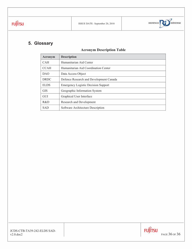
5. Glossary Acronym Description Table
Acronym Description
CAH Humanitarian Aid Center
CCAH Humanitarian Aid Coordination Center
DAO Data Access Object
DRDC Defence Research and Development Canada
ELDS Emergency Logistic Decision Support
GIS Geographic Information System
GUI Graphical User Interface
R&D Research and Development
SAD Software Architecture Description

UNCLASSIFIED SECUTIRY CLASSIFICATION OF FORM
(highest classification of Title, Abstract, Keywords)
UNCLASSIFIED
SECUTIRY CLASSIFICATION OF FORM
DOCUMENT CONTROL DATA
1. ORIGINATOR Fujitsu Consulting (Canada) Inc. 2000, Boul. Lebourgneuf, Bureau 300, Québec (Québec) G2K 0B8
2. SECURITY CLASSIFICATION UNCLASSIFIED (NON-CONTROLLED GOODS) DMC A REVIEW: GCEC JUNE 2010
3. TITLE Emergency Logistics Decision Support (ELDS) – Software Architecture Description (SAD)
4. AUTHORS Frédéric Therrien and Sébastien Paquet, from Fujitsu Consulting (Canada) Inc.
5. DATE OF PUBLICATION
December 09, 2010
6a. NO. OF PAGES 36
6b .NO. OF REFERENCES 0
6. DESCRIPTIVE NOTES
Contract Report
7. SPONSORING ACTIVITY
N/A 9a. PROJECT OR GRANT NO. JCDS21 Core Test-bed Task Authorization 39
9b. CONTRACT NO.
W7701-5-3182
10a. ORIGINATOR’S DOCUMENT NUMBER DRDC CR 2011-623
10b. OTHER DOCUMENT NOS
11. DOCUMENT AVAILABILITY Unlimited distribution Restricted to contractors in approved countries (specify) Restricted to Canadian contractors (with need-to-know) Restricted to Government (with need-to-know) Restricted to Defence departments Others
12. DOCUMENT ANNOUNCEMENT Unlimited

UNCLASSIFIED SECUTIRY CLASSIFICATION OF FORM
(highest classification of Title, Abstract, Keywords)
UNCLASSIFIED
SECUTIRY CLASSIFICATION OF FORM
13. ABSTRACT
This document is a summary of the work done during the project “JCDS21 Core Test-bed Task Authorization 39, Emergency Logistics Decision Support (ELDS)”. It does not detail the various deliverables but it instead describes the different tasks that were completed and it identifies the key decisions or conclusions that were made.
14. KEYWORDS, DESCRIPTORS or IDENTIFIERS ELDS, decision support, emergency management, localisation algorithm, routing algorithm.

www.ddrdc rddc.ggc.ca