o0in a novel optoelectronic sysiem for m wadistortion ... · 9orig~uas gm% , 1. iot public seloavm...
TRANSCRIPT
In A Novel Optoelectronic Sysiem foro0M waDistortion-Invariant ATR
1%. Contract No. N00014-93-C-0135
Period of Performance: 07/02/93 to 01/02/94
Final Report
Reporting Period: 07/02/93 to 02/01/94 ' .... I.CELECTF
Presented to: APR 121904Office of Naval Research S D800 North Quincy Street F
Arlington, VA 22217-5660
Technical Monitor
William MiceliThis document hu •een opprov.,
9Orig~uas gm% , 1. iot public seloavM and sOle its'platoeg AU bIlO ."P!'oduot.i
tonas -l~l, .,, k. and Presented by:
Physical Optics Corporation
Research & Development Division
20600 Gramercy Place, Suite 103
Torrance, California 90501
Principal Investigator
94-11032 Lev Sadovnik
~~ ~ ~ jI~~ (310) 320-3088 DTIIC UAr7:p*.?ED
March 1994
Research supported by Strategic Defense Initiativellnnovative Science and Technology andmanaged by the Office of Naval Research
S41 1Final 0394.3225 SDI-ATR

DISCLAIMER NOTICE
THIS DOCUMENT IS BEST
QUALITY AVAILABLE. THE COPY
FURNISHED TO DTIC CONTAINEDA SIGNIFICANT NUMBER OF
COLOR PAGES WHICH DO NOT
REPRODUCE LEGIBLY ON BLACK
AND WHITE MICROFICHE.

I Formn ApprovedREPORT DOCUMENTATION PAGE 0MB No. 0704-08o
Public reporting burden for this collecion of information is estimated to average 1 hour per mrponse, including the time for reviewing instrution. searching existing data sources. gatheringand maintaining the data needed. and completing and reviewing the collection of information. Send commennts regarding this burden estimate or any other aspect of the colecion ofinformation, including suggestons for reducing this burden to Washington HeadQuauters Service. Directorate for inlomatlion Operations and Reports. 1215 Jeldfewon Davis Higbway. Suis1204. Arlington. VA 22202-4302, and to the Office of Management and Budget. Paeeort,k Reduction Project (0704-0186). Washington. DC 20503.
1. AGENCY USE ONLY (Leave blank) 2. REPORT DATE 3. REPORT TYPE AND DATES COVERED
S2-1-94 Final 7-2-93 through 2-1-944. TITLE AND SUBTITLE 5. FUNDNG NUMBERS
A Novel Optoelectronic System for Distortion-Invariant ATR C: N00014-93-C-0135
6. AUTHOR(S)
Lev Sadovnik
7. PERFORMING ORGANIZATION NAME(S) AND ADDRESS(ES) 8. PERFORMING ORGANIZATIONREPORT NUMBER
Physical Optics Corporation20600 Gramercy Place, Building 100 3225Torrance, California 90501
9. SPONSORING / MONITORING AGENCY NAME(S) AND ADDRESS(ES) 10. SPONSORING / MONITORINGAGENCY REPORT NUMBER
Office of Naval Research800 North Quincy StreetArlington, VA 22217-0135
11. SUPPLEMENTARY NOTES
12a. DISTRIBUTION/ AVAILABILITY STATEMENT 12b. DISTRIBUTION CODE
Unlimited
13. ABSTRACT (Maximum 200 words)
The proposed idea is to enhance existing optical correlation based automatic target recognition (ATR) byintroducing scale, translation, and rotation invariance (STRI). Previously, STRI was achieved by utilizinga library of matched filters corresponding to various positions of rotation and scale variation. We find thatsimple preprocessing can eliminate the need for the library since any STR changes in the input image canbe nullified by bringing an input image to what we call its archetype.
Physical Optics Corporation's (POC's) new approach includes a segmentation preprocessor (required toselect any potential object of interest in an image of a realistic scene), POC's invariant preprocessor, and astandard optical correlator. This combination will greatly increase recognition speed and will simplify therecognition training procedure since only one in-plane position of the target will be needed to provide STRIrecognition.
The Phase I research described in this report opened a new approach to invariant ATR in which in-planeobject position will no longer be of concern and, therefore, the best matched filter can be exploited to attainmaximum confidence of identification. This should result in the development of hardware capable ofoperating in a real-time mode.
14. SUBJECT TERMS 15. NUMBEROF PAGES
Automatic Target Recognition 2816. f'H f;kUU:
17. SECURITY CLASSIFICATION 18. SECURITY CLASSIFICATION 19. SECURITY CLASSIFICATION 20. LIMITATION OF ABSTRACT
OF REPORT OF THIS PAGE OF ABSTRACT
Unclassified Unclassified Unclassified SARNSN 7540-01-280-5500 Standard Form 298 (Rev. 2-89)
Prescribed by ANSI Std Z39-18298-102

Final Rpt 0394.3225 SDM-ATN
N00014-93-C-0135
Executive Summary
In this report, we provide a theoretical proof and an experimental verification of a new approach to
invariant automatic target recognition (ATR) proposed by Physical Optics Corporation (POC). The
core of the concept is to determine the so-called archetype image for a class of all images derived
from a given object through scale, translation and rotational (STR) changes. This archetype image
will then represent the whole class of STR transformations and can be used for further
identification. We started with a comparative analysis of the moments transformation which is the
closest related approach. Next, we developed an algorithm for bringing an input image to its
archetype position. We tested this algorithm in the presence of added noise and varying
illumination. We also confirmed the robustness of the algorithm performance experimentally by
using an optical correlator to classify the obtained archetype images. At the end of this report we
outline the proposed ATR system development.
A'ces! oil •,orN riS
By ........................
D Ast ib pIc ia
SAvail ario I orDist Special
Fina Rpt 0394.3225 SDI-ATRN00014-93-C-0135
TABLE OF CONTENTS
1.0 INTRODUCTION ................................................................................... 1
2.0 PREVIOUS WORK ON INVARIANT PATTERN RECOGNITION ..................... 3
2.1 Orthogonal Fourier-Mellin Moments (OFMMs) ........................................... 4
2.2 Procedure for Computing the OFMM Features ........................................... 7
2.3 Conclusions Regarding the Use of OFMMs ............................................. 9
3.0 PROOF OF STRI PREPROCESSING ALGORITHM ......................................... 9
4.0 DIGITAL IMAGE ROTATION ................................................................... 12
5.0 EXPERIMENTAL PROOF OF STRI ALGORITHM ........................................ 15
5.1 STRI Algorithm Demonstration ............................................................... 15
5.2 Noise Tolerance and Illumination Invariance ............................................. 18
6.0 OPTICAL IMPLEMENTATION ............................................................... 22
7.0 CONCLUSION .................................................................................. 26
8.0 PHASE II SUGGESTIONS ................................................................... 28
9.0 REFERENCES ................................................................................... 28

Fina Rpt 0394.3225 SDI-ATR
N00014-93-C-0135
LIST OF FIGURES AND TABLES
Figure 1-1 Block diagram of ATR ................................................................. 1
Figure 1-2 Image complexity string ............................................................ 2
Figure 1-3 Reducing image complexity ........................................................... 2
Figure 4-1 POC's image processing station ..................................................... 13
Figure 4-2 Interpolation method ................................................................ 14
Figure 5-1 A set of models used for the STRI experiment ..................................... 16
Figure 5-2 Example of STRI processing performed on two airplane models ........... 17
Table 5-1 MSE of STRI Processor .......................................................... 18
Figure 5-3 Performance of the STRI processor on an image scene with low contrast
external noise ........................................................................... 19
Figure 5-4 Same as Figure 5-3. Model C .................................................. 20
Figure 5-5 Same as Figure 5-3. Model B .................................................. 21
Figure 6-1 Schematic of the optical implementation of the STRI ATR system .............. 22
Figure 6-2 POC's correlator combined with the STRI preprocessor ...................... 23
Figure 6-3 Auto correlation and cross correlation peaks observed at the system
output ................................................................................. 24
Figure 6-4 Images of the model as they appeared on the input SLM after
preprocessing ........................................................................... 25
Figure 6-5 Correlation output from the multiplexed matched filter for the two targets
shown in Figure 6-4 .............................................................. 26
Figure 7-1 Diagram of STRI preprocessor operation ........................................ 27
Figure 8-1 STR invariant WT for ATR ...................................................... 28

Fina Rpt 03•4.3225 SDI-ATRN00014-93-C-0135
1.0 INTRODUCTION
The goal of this research is to develop a new concept of scale, translation, and rotation invariant
optical processing for ATR. Research on invariant ATR has been underway for the last thirty to
forty years, motivated by various military and commercial applications, the latter including on-line
control, robotic vision and biomedical analysis (such as used in cytopathology). The general
requirements for invariant ATR have been developed over the years and can be stated as:
- Invariant mapping of an input image onto a feature space
- Unique classification and/or identification.
A fully invariant system would perform ATR without regard to translation (shift), rotation, dilation
(scale), and illumination or viewing angle. In this project, we limit our investigation to the first
three invariant features only, although we suggest methods for incorporating the other two.
The principle of invariant ATR can be reduced to a block diagram shown in Figure 1-1. The
transforms take the form of Fourier, Gabor, windowed, wavelet or some other integral
transformations. Matching can be done either by using a prestored filter (matched filter) or a
continuously updated (joint transform correlator) filter. Final identification is typically done by
choosing some distance function in a feature space such as Euclidean, Mahalanobis, or minimum
entropy.
Tra Jfo m m Match IIdnify
Figure 1-1Block diagram of ATR.
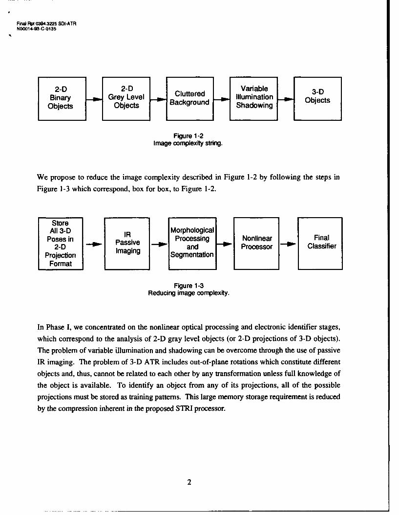
Figure 1-2 shows a hierarchy of images of increasing complexity, beginning with simple 2-D
binary objects at the left and increasing in complexity to the right. The procedure illustrated in
Figure 1-1 has not been fully successful for realistic 3-D objects whose increased image
complexity can be described by Figure 1-2.
Final Rpt 0394.3225 SOI-ATRN00014-93-C-0135
2-D 2-D Variable 3-DBinary Grey Level Cluttered Illumination ObjectsObjects Objects Background Shadowing
Figure 1-2Image complexity string.
We propose to reduce the image complexity described in Figure 1-2 by following the steps in
Figure 1-3 which correspond, box for box, to Figure 1-2.
StoreAll 3-D IR Morphological
Poses in Processing Nonlinear Final2-D i Passive and Processor • Classifier
Projection Imaging SegmentationFormat
Figure 1-3Reducing image complexity.
In Phase I, we concentrated on the nonlinear optical processing and electronic identifier stages,
which correspond to the analysis of 2-D gray level objects (or 2-D projections of 3-D objects).
The problem of variable illumination and shadowing can be overcome through the use of passive
IR imaging. The problem of 3-D ATR includes out-of-plane rotations which constitute different
objects and, thus, cannot be related to each other by any transformation unless full knowledge of
the object is available. To identify an object from any of its projections, all of the possible
projections must be stored as training patterns. This large memory storage requirement is reduced
by the compression inherent in the proposed STRI processor.
2

Finm Rpt 94,3225 SOI-ATR
NM0014-9W-C-0135
2.0 PREVIOUS WORK ON INVARIANT PATTERN RECOGNITION
In this section, we describe advances made in STRI ATR to date.
Pattern recognition is of interest in many disciplines, since it can provide automatic recognition of
signals and objects. Optical pattern recognition, in particular, will provide tools for machine
vision, robotics, automation and image understanding, by taking advantage of the parallel
processing capabilities of optics.
One of the main demands placed on a recognition system is that it be invariant to changes in input,
i.e., that it enable object recognition or classification, even when the object is distorted due to
changes in position, rotation or size.
Even digital ATR is a challenging task. There is no universal approach that can recognize targets in
any circumstances. The key issue is the feature extraction that determines the pattern recognition.Human beings easily determine the most significant features of images. Machines may not be able
to adaptively choose the feature extraction algorithm that is suitable to the circumstance.
We evaluated the performance of the following algorithms of invariant feature extraction and
pattern recognition:
1. Orthogonal Fourier-Mellin Moments (OFMMs);
2. Fourier Descriptors (FDs);3. Geometrical approach to multiple circular harmonic filters (CHFs);
4. Phase-only Synthetic Discriminate Function (SDF) filters;
5. Composite wavelet matched filters;
6. Fourier-Me~lin Descriptors (FMDs);
7. Image normalization using low-order Fourier-Mellin moments;
8. Moment invariants;
9. Phase-only covariance circular harmonic filters;
10. Wavelet matched filters.
We performed computer experiments using those algorithms. The conclusion of our investigationwas that OFFMs are superior over other approaches. However, this method is computationallyintensive and does not provide sufficient noise tolerance since high order moments are involved.
3
FinW IPV 0804.3225 SOI-ATR
NO0O14-93-C-0135
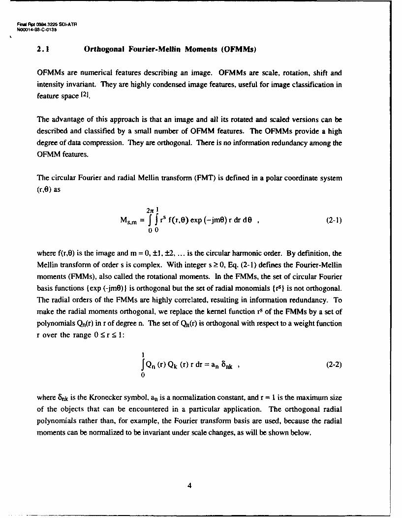
2.1 Orthogonal Fourier-Mellin Moments (OFMMs)
OFMMs are numerical features describing an image. OFMMs are scale, rotation, shift and
intensity invariant. They are highly condensed image features, useful for image classification in
feature space [2].
The advantage of this approach is that an image and all its rotated and scaled versions can be
described and classified by a small number of OFMM features. The OFMMs provide a high
degree of data compression. They are orthogonal. There is no information redundancy among the
OFMM features.
The circular Fourier and radial Mellin transform (FMT) is defined in a polar coordinate system
(r,0) as
2n 1MsIm= f J rs f(r,o) exp (-jmO) r dr d , (2-1)
00
where f(r,O) is the image and m = 0, ±1, ±2, ... is the circular harmonic order. By definition, the
Mellin transform of order s is complex. With integer s > 0, Eq. (2-1) defines the Fourier-Mellin
moments (FMMs), also called the rotational moments. In the FMMs, the set of circular Fourier
basis functions I exp (-jmO)) is orthogonal but the set of radial monomials { rs I is not orthogonal.
The radial orders of the FMMs are highly correlated, resulting in information redundancy. To
make the radial moments orthogonal, we replace the kernel function rs of the FMMs by a set of
polynomials Qn(r) in r of degree n. The set of Qn(r) is orthogonal with respect to a weight function
r over the range 0<r 1:
1JQn (r) Qk (r) r dr = an nk , (2-2)
0
where 8k is the Kronecker symbol, an is a normalization constant, and r = 1 is the maximum size
of the objects that can be encountered in a particular application. The orthogonal radial
polynomials rather than, for example, the Fourier transform basis are used, because the radial
moments can be normalized to be invariant under scale changes, as will be shown below.
4

FRn Rp 0304.3225 SMATRNOOO14-W-C-0135
The orthogonal Fourier-Mellin moments (OFMMs) are defined as
+I2xI
Onm fn_! f Jf (r,O) Qn (r) exp (-jmi) r dr dO (2-3)0 0
and are integrable when the degree of Qn(r), n > 0. The basis functions Qn(r) exp(-jmO) of the
OFMMs are orthogonal over the interior of the unit cLicle.
The orthogonal polynomials Qn(r) are obtained by applying the Schmidts process of
orthogonalization to a sequence of natural powers of r over the range 0 5 r < 1
1, r, r2 ..... rn .(2-4)
By using Jacobi polynomials Gn(p,q,r), we obtain the polynomials Qn(r) corresponding to the
Jacobi polynomials with p = q = 2:
Qn (r)=(-l)n (n I)G" (2, 2, r)= Xans rs, (2-5)s=O
with
ans = (_1 )n +s (n +s+ 1)! (2-6)(n - s)! s! (s + 1)!
The normalization constant in Eq. (2-2) is an = l/[2(n + 1)]. The explicit expressions of Qn(r)are:
Qo(r) =
QI (r) = - (2 - 3r)
Q2 (r) = 3 - 12r + lOr 2
Q3 (r) = - (4 - 30r + 60r 2 - 35r3)
Q4 (r) = 5 - 60r + 210r 2 - 280r3 + 126r 4
Q5 (r) = - (6 - 105r + 560r2 - 260r 3 + 1260r4 - 462r5)
5

Find RpO X04.3225 SOI-ATRN00014-03-C-0135
Substituting Eqs. (2-1) and (2-5) into Eq. (2-3), we express the OFMMs as linear combinations of
the FMMs
(nm = n+1 •Xns Msm (2-7)S=0
The OFMMs can be normalized to be invariant under rotation, scale, and intensity changes, as we
will show below.
The FMMs and the OFMMs can also be defined in the Cartesian coordinate system as modified
complex moments (CMs) and orthogonal CMs, respectively. This is important because, in most
cases, images are presented in a Cartesian coordinate system. Calculating the OFMMs directly in
the Cartesian coordinate system can avoid the coordinate transform of the image from the Cartesian
to the polar coordinate system.
The orthogonal basis functions Qn(r) exp (-jmO) of the OFMM can be expressed as complex
polynomials in (x + jy) and (x - jy). The CMs are defined in both the Cartesian and the polar
coordinate system [3]:
00
CpqfJ Jf(x,y) (x + jy)P (x- jy)q dxdy-_00
2x 1 (2-8)
= f J f(r,0) rs exp (-jmO) r dr dO00
with s = p + q and m = q - p. By the definition of Abu-Mostafa and Psaltis, the orders
p and q are non-negative integers. From Eqs. (2-5) and (2-7),
n nQn (r) exp (-jmO)= an,s rs exp (-jmO)= Xtn,s(X + jy)P (x - jy)q , (2-9)
s=O s=O
are a set of complex polynomials of degree n = p + q, where
s-in s+mp and q = S (2-10)2 2
6
FinwJ Rpt 0384.3225 SDI-ATRN00014-93-C-0135
orthogonal inside a unit circle. Hence, the OFMM can be expressed as a linear combination of the
CMs as
n+l nnm •a Csm s+m (2-11)s=O 2 ' 2
s-rn s+m
where the orders -- and --- of the CMs, Cpq, are real-valued and can be negative-valued.2 2
Under the conditions that both p + q = s and q - p = m are integers and s = p + q _> 0, the
modified CMs are convergent and integrable.
In the following experiments, the OFMMs will be calculated as the orthogonal CMs expressed in
Eq. (2-11).
2.2 Procedure for Computing the OFMM Features
The steps in computing the OFMMs of an image follow.
1. Determine the center of the image by using the first order of the geometrical moments of the
image:
x0 = M1 0 Y = M0-1 , (2-12)MOO MOO
where the geometrical moments mpq are defined as
00
mpq= Jf(x,y) xp yq dx dy (2-13)
With the center of the image as the origin of the coordinate system, the moments calculated
in this coordinate system would be shift invariant.
2. Calculate the FMMs, Msm, defined in Eq. (2-1), by calculating the correspondings-mn s+m
modified complex moments Ciq described in Eq. (2-8) with p = - and q -2 2
in the Cartesian coordinate system;
7

Final Rpt 0394.3225 SDI-ATRN00014-93-C-0135
3. Normalize the FMMs for the scale and illumination invariance. When the object f(r,O) is
scaled by a factor k and its intensity is changed by a factor g, its FMMs become
2igMsm = j J gf (r/k, 0) rs rdr dO = gks+ 2 Msm (2-14)
00
The scale and intensity factors k and g are obtained using the low order FMMs:
Mo= gk Moo (2-15)
M = gk 3 M10
The scale factor k is equal to
=,.- .)/!,.MOO) "(2-16)
The intensity factor g is equal to
g M=2 [LMo- (2-17)g [MOO) MOOj (Moo)
Using the factors k and g, the FMMs may be normalized as
MMsm (2-18)Msm - (-S+2
The normalized FMMs are scale and intensity invariant.
4. Calculate the OFMMs using Eq. (2-7) and the normalized FMMs. A rotation of the image
by an angle 00 results in the same phase factor exp (jmOo) for all the Msm in Eq. (2-7).The modulus of the OFMM, IOInml, is rotation invariant.
8

Final Rpt 0394.3225 SDI-ATRN00014-93-C-0135
4. Calculate the OFMMs using Eq. (2-7) and the normalized FMMs. A rotation of the image
by an angle Oo results in the same phase factor exp (jimo) for all the Msm in Eq. (2-7).The modulus of the OFMM, 14),nl, is rotation invariant.
2.3 Conclusions Regarding the Use of OFMMs
Although superior to other known STRI algorithms, OFMM-based ATR suffers from
low noise tolerance (especially if it is introduced far from the center of the
image frame)
- computational intensity (for a large number of moments)- no optical (parallel processing) implementation.
3.0 PROOF OF STRI PREPROCESSING ALGORITHM
POC's proposed STRI ATR concept eliminates the main deficiencies of previous algorithms: the
proposed algorithm is robust and noise tolerant and ready for optical implementation in a standard
coherent optical system.
The proposed idea enhances existing optical correlation based ATR by introducing scale,
translation and rotation invariance (STRI). Previously, STRI was achieved by utilizing a library of
matching filters corresponding to various positions of rotation and scale. We find that simple
preprocessing can eliminate the need for the library since any STR changes in the input image can
be nullified by bringing the input image to, as we call it, its archetype. This means that any STR
transformation of the target can be reduced to the initially defined target archetype. The archetype
fully determines the whole class of STR transformed images of the given target.
This archetype image is characterized by the following features:
• Its center of gravity is coincident with a predetermined origin.
* It has a certain angle, specific to a given image, with the horizontal and vertical
axes.
It always has the same predetermined scale.
9

Final Rpt 0394.3226 SDI-ATRN=014-93-C-O035
Translation invariance is achieved the same way as in moment transforms. Namely, for a given
image l(x,y), the center of gravity (xc, Yc) can be found by using the following expressions:
JJ xI(x, y)dx dy
XC = JJI(x, y)dx dy
(3-1)JJyl(x,y)dxdy
Yc =�-JI(x,y)dxdy
where 0 is the area of an input frame. The assumption is made that the input image is contained
inside the input frame. Then, by shifting the input image by a vector [xýYcl
x' = C (3-2)Y' Y - Y
we bring the image to the origin. (x',y') are the new coordinates of the image.
The most striking aspect of the proposed STRI concept is the rotation invariance property. In
order to prove it, let us consider a function V(O) that is obtained as a result of the integration of the
input image in polar coordinates:
R2n=(00) f J cos 0 I(r, 0 - 0o)rd0 dr, (3-3)
00
where R is the radius of the smallest circle covering the input frame.
By changing the variable to (p = 0 - 00 and using the formula for cos ((p + 0 o),
R 2n R 2nxV(00) = cos 00 j J'cos(p l(r,(p) drrdq + sin0 0 j j sin(p I(r,(p)rdrd p (3-4)
00 00
If we call the first double integral A and the second B, then the short-hand notation of Eq. (3-4) is
x(00) = Acos 00 - B sin 00 , (3-5)
10

Final Rpt 0394.3225 SDI-ATRN00014-93-C-0135
Of"
or0o(00) = cos 00 cos a - sin O0 sin a = cos(0o + a) , (3-6)
where
cos a = A/(A2 + B2)1/2 , sin a = B/(A2 + B2)1i 2 , V0 = Ni/(A 2 + B2)1/2 (3-7)
Clearly, in the interval from 0 to 21E, ,qo(0 ) has a single minimum, XVo(Oo) = -1, which is
achieved at
00o=7-o , (3-8)
regardless of the rotation of the input image. Thus, by computing the angle 00 (0 < U0 < 23r) by
00 = n - arctan (A/B) , (3-9)
whereR 21r
A = f fcos (p I(r,p)rdr d(p0 0 (3-10)R2x€
B=f fsin•pI(r,p)rdrdqp00
and rotating the input image by 00, the input image is brought to the archetypal angular position.
The last step is to normalize any changes in scale. This is achieved by computing the input image
norm M:
M= JJI(x,y)dxdy , (3-11)
and changing the coordinates by a scaling factor -,/M'. This will assure that the input image will benormalized, regardless of its initial scale. Indeed, if the input image is zoomed by a factor c, then
its new norm is
M, = ff1I (cx,cy)dxdy = M/c 2 , (3-12)
11
Final Rpt 0394.3225 SDi-ATRN00014-93-C-0135
and changing the coordinates by a scaling factor I/M. This will assure that the input image will be
normalized, regardless of its initial scale. Indeed, if the input image is zoomed by a factor c, then
its new norm is
Mc = fJI (cx,cy)dxdy = M/c 2 , (3-12)
and by changing the input image scale by a factor of NNW I we again bring the image to the samescale
I(cx. -JM-c , cy. 4c) =I(x. M, y. M), (3-13)
which is an image archetype, since M is constant for a given image.
4.0 DIGITAL IMAGE ROTATION
The STRI transformation expressed by Eqs. (3-2), (3-9) and (3-12) has been successfully tested at
POC.
POC's image-processing system consists of a Cohu CCD camera connected to a Matrox PIP video
digitizer board installed in an IBM-compatible 486/66 personal computer. A black and white TV
monitor was used to display the images. The image-processing station is shown in Figure 4-1.
The digitizer board is supplemented with a library of C-language commands which were used to
write the image-processing routines. The following is a summary of the tasks performed by these
routines:
12

Final Rpt 0394 3225 SDI-ATRN00014-93-C-0135
Figure 4-1POC's image processing station.
First, the image of the object obtained by the CCD camera is digitized into a 256 x 256 array of
8-bit pixels. This image is then thresholded to set the background and shadows to zero. At this
point, the center of gravity of the object is calculated with Eq. (3-1).
The object is then moved such that the center of the image area coincides with the center of gravity
of the object. The translation accuracy has an error not larger than one pixel, which results fromrounding up the numbers computed with Eq. (3-1).
The next task is to calculate the angle through which the object is to be rotated to reach its
archetype. This angle, 00, is calculated with the following equation:
0() = it - arc tan (A/B)
R2nt R27rwhere A = J J coso l(r,O)r dr do , B = J J sin0 I(r,O)r dr do (3-14)
(0 0 0 0
The rotation task presents problems not associated with simple translation. Image rotation is a
geometric process where one-to-one mapping of source to destination pixels is not guaranteed.
13
Final Rpt 0394.3225 SDI-ATRN00014-93-C-0135
The rotation task presents problems not associated with simple translation. Image rotation is a
geometric process where one-to-one mapping of source to destination pixels is not guaranteed.Without this one-to-one correspondence between source and destination pixels, it cannot be
guaranteed that one source pixel will be mapped to every destination pixel. This creates voids thatmake the rotated images unusable. We employ reverse mapping to prevent these voids. Reverse
mapping traverses the destination image space, a pixel at a time, and calculates, via the rotation
transformation, which pixels of the source image would be involved in producing the destination
pixel. When the value of the destination pixel is calculated in this manner and placed into the
destination image, complete coverage of the destination image is guaranteed.
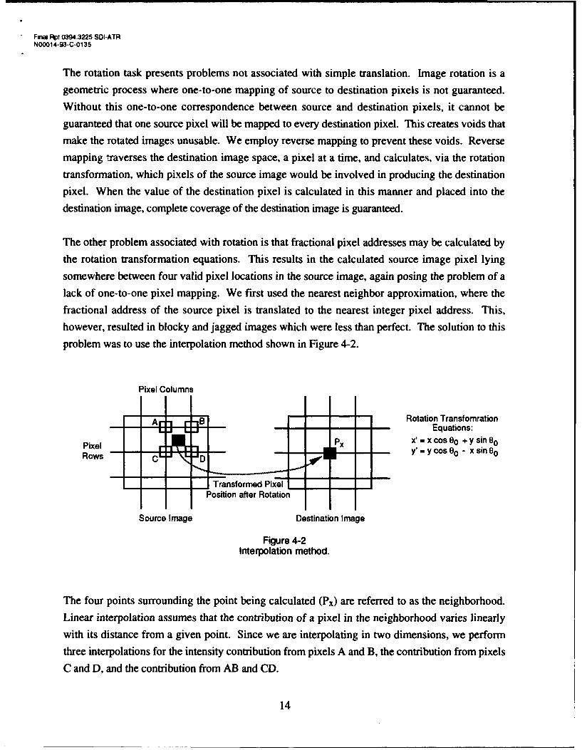
The other problem associated with rotation is that fractional pixel addresses may be calculated by
the rotation transformation equations. This results in the calculated source image pixel lying
somewhere between four valid pixel locations in the source image, again posing the problem of alack of one-to-one pixel mapping. We first used the nearest neighbor approximation, where the
fractional address of the source pixel is translated to the nearest integer pixel address. This,however, resulted in blocky and jagged images which were less than perfect. The solution to this
problem was to use the interpolation method shown in Figure 4-2.
Pixel Columns
Ar "1 -Bi -1 Rotation Transfomration. J -..-•. - Equations:
-I• x'-= x cos 00 + y sin 00Pixel Px = y cos 8 0 - x sin 0Rows C "-cD
Transformed Pixel
Position after Rotation
Source Image Destination Image
Figure 4-2Interpolation method.
The four points surrounding the point being calculated (Px) are referred to as the neighborhood.
Linear interpolation assumes that the contribution of a pixel in the neighborhood varies linearlywith its distance from a given point. Since we are interpolating in two dimensions, we perform
three interpolations for the intensity contribution from pixels A and B, the contribution from pixels
C and D, and the contribution from AB and CD.
14
Finai Rpt 0394.3225 SDI-ATRN00014-93-C-0135
The final problem associated with image rotation is the aspect ratio consideration. Because the TV
monitor is not square, the pixels are not square. Rotation of nonsquare pixels results in distorted
images. This problem was solved by using appropriate horizontal and vertical scale factors. The
combination of reverse mapping, linear interpolation, and aspect ratio correction results in the best
possible rotated images.
Two experiments were performed to test the operation of the image processing station. In the first
experiment, the image of an object was thresholded, translated to the center, and rotated through its
calculated characteristic angle. The original image of the object was then rotated through a random
angle in the computer, and the resultant image was processed through the above routines. The two
final images were compared and found to be identical. In the second experiment, the object was
located in two different positions and the program brought it to its archetype position. This
experiment also produced successful results.
5.0 EXPERIMENTAL PROOF OF STRI ALGORITHM
5.1 STRI Algorithm Demonstration
A set of 3-D objects, airplane models, was used to demonstration the STRI properties of the
proposed algorithm (see Figure 5-1).
15

Final Rpt 0394.3225 SOI-ATRN00014-93-C-0135
Figure 5-1A set of models used for the STRI experiment.
For every model, 25 arbitrary STR transformations were performed and mean square errors
(MSEs) were calculated for the resulting archetypes. The system (see Figure 4-1) operates in real-
time. The results for two arbitrary target positions was displayed in less than 3 seconds.
The error for the two arbitrary STR transformed images as they are brought to the archetype
position mainly occurs at the edges, as seen in Figure 5-2. Two randomly scaled images of thesame model displaced from the center of the frame and rotated are shown at the top of the screen
while one archetype (bottom left) and the difference between the two archetypes is shown at the
bottom right of the screen.
16

SnlHPI 0,494 ;22f, SDI AT RN)L)L)14 tj C 01ul
(a)
(b)
Figure 5-2Example of STRI processing performed on two airplane models.
17
Final Rpt 0394.3225 SDI-ATRN00014-93-C-0135
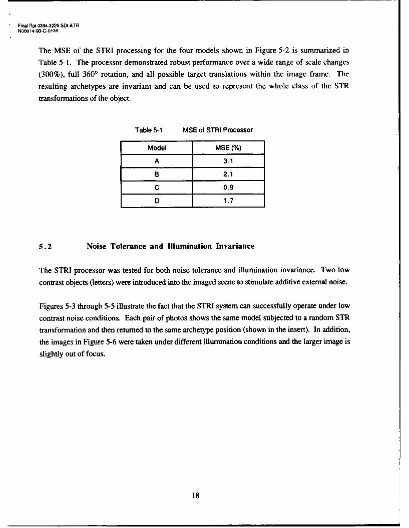
The MSE of the STRI processing for the four models shown in Figure 5-2 is summarized in
Table 5-1. The processor demonstrated robust performance over a wide range of scale changes
(300%), full 3600 rotation, and all possible target translations within the image frame. The
resulting archetypes are invariant and can be used to represent the whole class of the STR
transformations of the object.
Table 5-1 MSE of STRI Processor
Model MSE (%)
A 3.1
B 2.1
C 0.9
D 1.7
5.2 Noise Tolerance and Illumination Invariance
The STRI processor was tested for both noise tolerance and illumination invariance. Two low
contrast objects (letters) were introduced into the imaged scene to stimulate additive external noise.
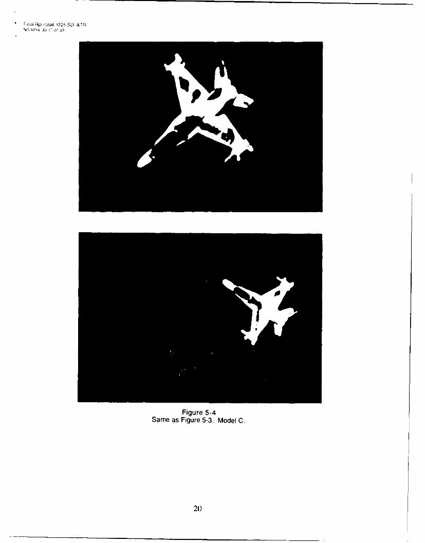
Figures 5-3 through 5-5 illustrate the fact that the STRI system can successfully operate under low
contrast noise conditions. Each pair of photos shows the same model subjected to a random STR
transformation and then returned to the same archetype position (shown in the insert). In addition,
the images in Figure 5-6 were taken under different illumination conditions and the larger image is
slightly out of focus.
18

,r•al R•q• 0394 3225 SDI A TRN00014 93-C 0 135
Figure 5-3Performance of the STRI processor on an image scene with low contrast external noise. Model Ais used here. The insert shows the system's reduction of the input model to the archetype.
19
Fnal Rp U-394 3225 SDI ATRNO0014 33.C 01 35
Figure 5-4Same as Figure 5-3. Model C.
2)

,:-nal Rpt 1394 3225 SD.ATRN00014 93 C.,)135
Figure 5-5Same as Figure 5-3. Model B. In addition, the illumination level is different for the two images.
21

FinaJ Rpt 0394.3225 SDI-ATRN00014-93-C-0135
6.0 OPTICAL IMPLEMENTATION
The developed STRI digital processor can be used to supply an invariant image archetype as an
input to an ATR system. Specifically, standard optical correlators fit very well with the STRI
algorithm that has been implemented in the Phase I work. The schematic diagram of the resulting
ATR system is shown in Figure 6-1.
Video Host ComputerInput
CoherentIllumination
Input Fourier Filter Fourier OutputSLM Transform Plane Transform CCD
Lens SLM Lens Array
Figure 6-1Schematic of the optical implementation of the STRI ATR system.
As was mentioned earlier, only one matched filter is needed for every target to accommodate all
possible in plane STR transformations. This is in sharp contrast to the standard optical correlator
where target rotations (typically of few degrees) and scale changes (usually larger than 5%) must
be recorded as a separate matched filter (or combined into a synthetic filter). The photograph in
Figure 6-2 shows a hardware implementation of an ATR system demonstrated at POC. For this
system, the previously demonstrated digital processor operates as a preprocessor for the optical
correlator. Since the matched filter for the archetype of the given target is recorded, any STR
transformed image of the object will trigger the correlation, resulting in a strong correlation peak
(see Figure 6-3). In this experiment, a DCG based matched filter accommodated a pair of targets
22

* Final Rpt 0394.3225 SDI-ATRN00014-93-C-0135
a pair of targets (Models B and C) through angular multiplexing. They were presented to thecorrelator using a liquid crystal spatial light modulator (SLM), as shown in Figure 6-4.
Figure 6-2POC's correlator combined with the STRI preprocessor.
23

- Final Rpt 0394,3225 SOI-ATRN00014-93-C-0135
Figure 6-3Auto correlation and cross correlation peaks observed at the system output.
(The bottom line seen on the oscilloscope is the intensity scan.)
24

Final Rpt 0394 3225 SD ATRNN0014 93 C 0135
Model B
Model C
Figure 6-4Images of the model as they appeared on the input SLM after preprocessing.
25

Final Rpt 0394.3225 SDI-ATRN00014-93-C-0135
Then, the STR transformed images trigger the corresponding matched filter to produce a
correlation output, as is seen in Figure 6-5. Thus, the preprocessor developed in this projectmakes the correlator fully STR invariant.
Figure 6-5Correlation output from the multiplexed matched filter for the two targets shown in Figure 6-4.
7.0 CONCLUSION
The operating principle of the developed STRI system is summarized in the flow chart in
Figure 7- 1.
26

FinaW Rpt 0394.3225 SDI-ATRN00014-93-C-0135
Segmentented Compute:
InputImage I(x, y) Center of Gravity Xc, Yc
True Rotation Angle aNorm M
Modify:
Shift x-x c, Y-Yc
Rotn cos a. -sin alRotation Lsin cos a
Scale TIx 47M M
Archetype of Input Image
Figure 7-1Diagram of STRI preprocessor operation.
The proposed concept is a significant step in the development of ATR systems, since it
* introduces complete factorization of the input space* provides full (theoretically unlimited) STR invariance
* does not require computation of higher order moments which negativelyaffect noise toleranceminimizes matched filter loads.
27
Fina Rp4t 0X394.3225 SDI-ATRN00014-93-C-0135
8.0 PHASE II SUGGESTIONS
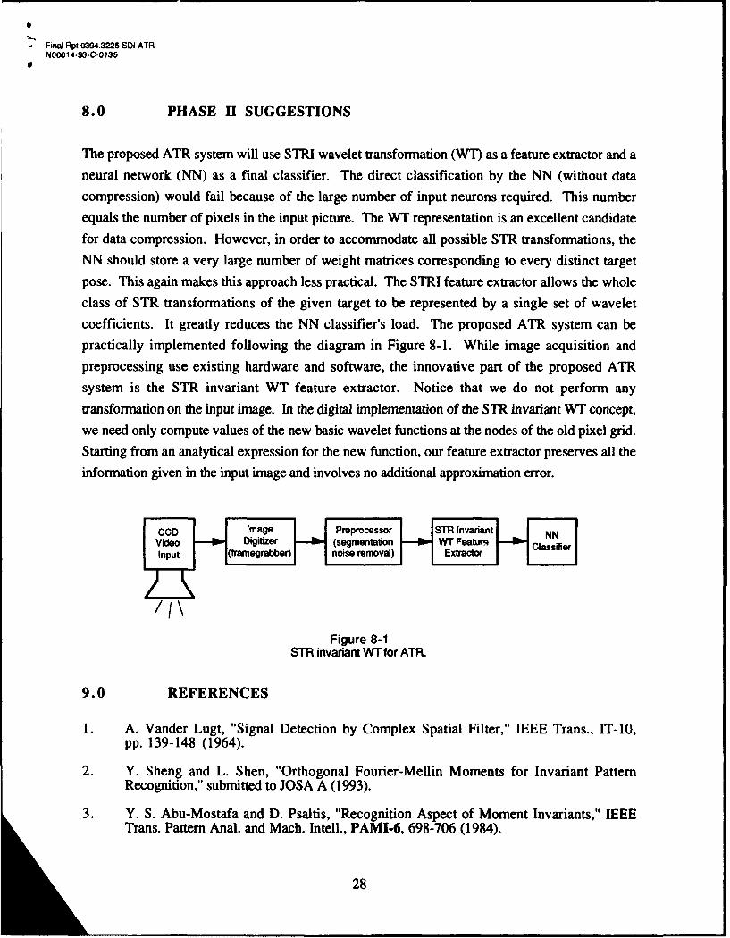
The proposed ATR system will use STRI wavelet transformation (WT) as a feature extractor and aneural network (NN) as a final classifier. The direct classification by the NN (without data
compression) would fail because of the large number of input neurons required. This numberequals the number of pixels in the input picture. The WT representation is an excellent candidatefor data compression. However, in order to accommodate all possible STR transformations, the
NN should store a very large number of weight matrices corresponding to every distinct target
pose. This again makes this approach less practical. The STRI feature extractor allows the whole
class of STR transformations of the given target to be represented by a single set of wavelet
coefficients. It greatly reduces the NN classifier's load. The proposed ATR system can bepractically implemented following the diagram in Figure 8-1. While image acquisition and
preprocessing use existing hardware and software, the innovative part of the proposed ATRsystem is the STR invariant WT feature extractor. Notice that we do not perform any
transformation on the input image. In the digital implementation of the STR invariant WT concept,we need only compute values of the new basic wavelet functions at the nodes of the old pixel grid.
Starting from an analytical expression for the new function, our feature extractor preserves all the
information given in the input image and involves no additional approximation error.
N V ideo - D igitizer H (segm en tattion W T Fea urq l ssf e
Figure 8-1STR invariant WT for ATR.
9.0 REFERENCES
1. A. Vander Lugt, "Signal Detection by Complex Spatial Filter," IEEE Trans., IT-10,pp. 139-148 (1964).
2. Y. Sheng and L. Shen, "Orthogonal Fourier-Mellin Moments for Invariant PatternRecognition," submitted to JOSA A (1993).
3. Y. S. Abu-Mostafa and D. Psaltis, "Recognition Aspect of Moment Invariants," IEEETrans. Pattern Anal. and Mach. Intell., PAMI-6, 698-706 (1984).
28