ø2 piping series - allied electronics · nbr pom, stainless steel note electroless nickel plated...
TRANSCRIPT

CAT.EUS50-25 A -UK
ø2 Piping Series
Minimum bending radius: 4mm
ø2
ø3.2, ø4
ø3.2, ø4
ø2Barb elbow
Barb fitting
Barb One-touch
Plug-in reducer
Series KJ
Series TU
ø2 One-touch fittings
Series KJ
ø2 Polyurethane tubing
Series TU
Series Mø2 Miniature fittings
Series M

Features 1
Sectional area113.04 mm2
Sectional area28.26 mm2
75%ø4
ø2
ø4 x 7
ø2 x 7
Reduction
Scale :100%
Scale :100%
Scale :100%
Scale :100%
Scale :100%
ø2 Polyurethane tubing
Series TU
Minimum bending radius: 4 mm
ø2 Miniature fittings
Series Mø2 One-touch fittings
Series KJ
Piping for compact actuator
Piping for compact pressure sensor

1
Series KJOne-touch Mini
Specifications
Applicable tubing material
Applicable tubing O.D.
Fluid
Maximum operating pressure
Operating vacuum pressure
Proof pressure
Ambient and fluid temperature
Copper-free (Standard)
Note 1) Applicable for general industrial water.
Polyurethane
ø2
Air, Water Note 1)
1 MPa
–100 kPa
3 MPa
–5 to 60°C, For water: 0 to 40°C (No freezing)
Brass parts are all electroless nickle plated.
Variation
Male connector
KJH
Hexagon socket head male connector
KJS
Straight union
KJH
Different diameter straight
KJH
Male elbow
KJL
Extended male elbow
KJW
Male branch tee
KJT
Union tee
KJT
Male run tee
KJY
Union "Y"
KJU
Different diameter union "Y"
KJU
Plug-in reducer
KJR
Bulkhead union
KJE
Plug
KJP
How to Order
KJ H M302Model
H
SLW
T
Y
U
RE
Male connectorStraight union
Different diameter straightHexagon socket head male connector
Male elbowExtended male elbow
Male branch teeUnion tee
Male run teeUnion "Y"
Different diameter union "Y"Plug-in reducerBulkhead union
Applicable tubing O.D. ø2
Port size
Note 1) Different diameter tubing O.D.
M3M5
Same diameter tubingø3.2ø4
M3M5002304
Note 1)
Note 1)
∗) Plug: KJP– 02
Applicable tubing O.D. : ø2Connection thread: M3
M5
2
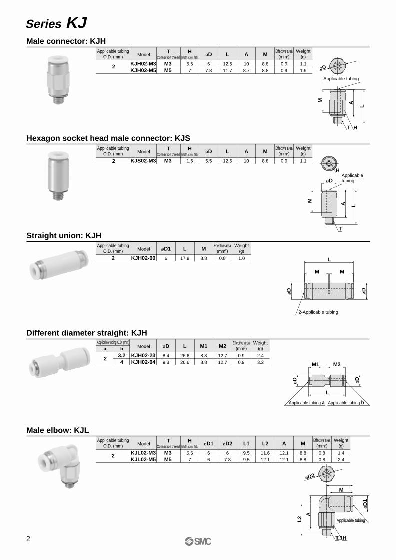
Series KJ Male connector: KJH
TConnection thread
M3M5
Model
KJH02-M3KJH02-M5
H(Width across flats)
5.57
øD
67.8
L
12.511.7
108.7
M
8.88.8
AApplicable tubing
O.D. (mm)
0.90.9
1.11.9
Effective area(mm2)
Weight(g)
0.9 1.1
Effective area(mm2)
Weight(g)
2
Hexagon socket head male connector: KJST
Connection thread
M3
Model
KJS02-M3
H(Width across flats)
1.5
øD
5.5
L
12.5 10
M
8.8
AApplicable tubing
O.D. (mm)
2
Model
KJH02-00
øD1
6
L
17.8 8.8
MApplicable tubing
O.D. (mm)
2
Straight union: KJH
Male elbow: KJLT
Connection thread
M3M5
Model
KJL02-M3KJL02-M5
H(Width across flats)
5.57
øD1
66
øD2
67.8
9.59.5
L2
11.612.1
L1
12.112.1
M
8.88.8
AApplicable tubing
O.D. (mm)
2
Different diameter straight: KJH
3.24
Model
KJH02-23KJH02-04
øD
8.49.3
L
26.626.6
8.88.8
M2
12.712.7
M1Applicable tubing O.D. (mm)
a b
2
0.8 1.0
Effective area(mm2)
Weight(g)
0.90.9
2.43.2
Effective area(mm2)
Weight(g)
0.80.8
1.42.4
Effective area(mm2)
Weight(g)
HT
Applicable tubing
A L
M
øD
T
HApplicable tubing
M
øD
A L
T H
Applicable tubing
A
L1
L2
M
øD2
øD
1M1 M2
L
øD
øD
Applicable tubing a Applicable tubing b
2-Applicable tubing
øD
M
øD
M
L

3
Series KJ
Model
KJT02-00
øD
6
L
10 4.9
Q
8.8
MApplicable tubing
O.D. (mm)
2
Union tee: KJT
Extended male elbow: KJWT
Connection threadModel
KJW02-M3KJW02-M5
H(Width across flats)
5.57
M3M5
øD1
66
øD2
67.8
9.59.5
L2
18.619.1
L1
19.119.1
M
8.88.8
AApplicable tubing
O.D. (mm)
2
Male branch tee: KJYT
Connection threadModel
KJY02-M3KJY02-M5
H(Width across flats)
5.57
M3M5
øD1
66
øD2
67.8
1010
L2
1010
L3
11.612.1
L1
19.119.1
M
8.88.8
AApplicable tubing
O.D. (mm)
2
Male branch tee: KJTT
Connection threadModel
KJT02-M3KJT02-M5
H(Width across flats)
5.57
M3M5
øD1
66
øD2
67.8
9.59.5
L2
11.612.1
L1
12.112.1
M
8.88.8
AApplicable tubing
O.D. (mm)
2
0.80.8
2.64.5
Effective area(mm2)
Weight(g)
1.11.1
1.82.8
Effective area(mm2)
Weight(g)
1.11.3
1.92.9
Effective area(mm2)
Weight(g)
0.9 1.7
Effective area(mm2)
Weight(g)
H
TApplicable tubing
M
L1
L2 A
øD
1
øD2
H
T
2-Applicable tubing L1
L2
L3
øD
1
A
øD1
øD2
M
M
øD øD
øD
M ML L
QML
Q Q
Q
ø5.2ø3.2
2-Applicable tubing
øD
1
øD2
L1M M
T
L2 A
H
L1
øD
1

Series KJ
Modela b
øD1
66
øD2
67.8
28.828.2
L2
19.218.5
L1
8.49.3
Q
5.86.3
P
8.88.8
M2
12.712.7
M1Applicable tubing O.D. (mm)
23.24
Different diameter union "Y": KJU
Applicable tubing b
ø3.2
ø6
øD1P
M1
øD2Q
L2
L1
M2
Model
KJU02-00
KJU02-23KJU02-04
øD
6
L1
20.1 13.4
L2
6.5
P
4.6
Q
8.8
MApplicable tubing
O.D. (mm)
2
Union "Y": KJU
3-Applicable tubing
P
L2
L1
øD
Q
MM
øD
ø3.2
ø5.2
Plug-in reducer: KJR
Model
KJR02-04
øD
6
L
28.3 15.6
M
8.8
AApplicable tubing
O.D. (mm)
2
Applicable fittingsize ød
4
Applicable fitting
Applicable tubing
L
ød
øD
M
A
Bulkhead union: KJET
Connection thread
M7 x 0.75
Model
KJE02-00
H(Width across flats)
9
L
18.1
Mountinghole
8 8.8
M
2
Applicable tubingO.D. (mm)
M7 x 0.75
H
2-Applicable tubing
Mounting plate thickness6 mm or less 2
MM
L
Model
KJP-02
øD
3
L
17 8.2
AApplicable tubing
O.D. (mm) ød
2
Plug: KJP
Applicable fitting size ød
4
LA
øD
ød
0.9 1.8
Effective area(mm2)
Weight(g)
1.51.6
4.76.0
Effective area(mm2)
Weight(g)
0.9 0.7
Effective area(mm2)
Weight(g)
0.8 3.7
Effective area(mm2)
Weight(g)
0.1
Weight(g)
2-Applicable tubing a

Series M Miniature Fittings
M 5 2AU
Specifications
Applicable tubing material
Applicable tubing (O.D. / I.D.)
Max. operating pressure (at 20°C)
Port size
Thread
Polyurethane
ø2 / ø1.2
1 MPa
M3, M5, ø3.2, ø4
JIS B0209 Class 2 (Metric coarse thread)
How to Order
Miniature fitting Applicable tubing (O.D. / I.D.)2 ø2 / ø1.2
ModelAU
ALUALHU
FR
Barb fitting
Barb elbow
Barb One-touchPlug-in reducer
M3, M5M3M5
ø3.2, ø4
Port size35
3204
M3M5
ø3.2ø4
Tubing Connection and Removal
Installing tubing1. Cut the tubing perpendicularly allowing
additional length.2. Insert the tubing into the sleeve.
3. Insert the tubing slowly into the fittings. Make sure to secure a gap of approx.0.5 mm between the tubing end and the barb end.
4. Insert the sleeve slowly. Make sure not to allow any gap between the sleeve end side and the body end side. (Please refer to the illustration below.)If you feel any strong resistance and cannot push the sleeve completely to the end side, this may be due to jamming. Remove and repeat again by starting from step 1 making sure to secure a gap in the step 3.
Sleeve
Gap (approx. 0.5 mm)
There should not be any gap.
Note) When installing the tubing, the sleeve must be attached. Operation without attaching the sleeve may cause disconnection of the tubing.
Removing tubing1. Withdraw the sleeve straight along the
tubing. Use a tool such as long-nose pliers if it is difficult to pull out by hand.
2. Withdraw the tubing straight.3. When reusing the tubing, cut off the
previously installed portion of the tubing to avoid possible leakage and/or disconnection of the tubing.
Applicable tubing O.D. x I.D. : ø2 x ø1.2Connection thread : M3 / M5One-touch fitting size : ø3.2 / ø4
5
BarbEasy tube insertionHigh retaining force
SleeveAttaching the sleeve achieves a large retaining force.Detaching it allows easy removal of the tube.Electroless nickel plated.
Gasket
Connection thread One-touch fitting
Low clamping torqueFirm sealing
Tubing
BodyElectroless nickel plated

6
Barb fitting: M-3AU-2, M-5AU-2
Series M
Applicable tubingO.D. x I.D. (mm) Thread
M3M5
Model
M-3AU-2M-5AU-2
H
4.57
A
910
B
34
D
57.7
F
0.90.71.5
C
4
E
4ø2 x ø1.2
Weight(g)
No.123
DescriptionSleeve
Barb fittingGasket
MaterialBrassBrass
NBR, Stainless steel
NoteElectroless nickel platedElectroless nickel plated
–
Component Parts
Thread
Width across flats H
Applicable tubing
øF
A
B C
øDøE
3 2 1
Barb elbow: M-3ALU-2, M-5ALHU-2Applicable tubingO.D. x I.D. (mm) Thread
M3M5
Model
M-3ALU-2M-5ALHU-2
H
57
A
911
B
6.57.5
C E F
0.92.53
G
2.53.5
I
9.413.5
J
57
Weight(g)
1.63.5
D
44ø2 x ø1.2
No.1234
DescriptionSleeveStud
Barb elbowGasket
MaterialBrassBrassBrass
NBR, Stainless steel
NoteElectroless nickel platedElectroless nickel platedElectroless nickel plated
–
Component Parts Width across flats H
Thread
Applicable tubing 43 2 1
�J
øD
øE
I
GF
A
B
C
Barb One-touch: M-32F-2, M-04F-2Applicable tubing (mm)
a (O.D. x I.D.) b (O.D.)ø3.2ø4
ø2 x ø1.2
Model
M-32F-2M-04F-2
A
17.718
B
13.714
7.58.5
D
0.9
M
2.42.9
C
4
E
12.7
Weight(g)
No.1234
DescriptionSleeveBodySeal
Cassette
MaterialBrassBrassNBR
POM, Stainless steel
NoteElectroless nickel platedElectroless nickel plated
––
Component Parts 4 3 2 1
øCøD
øE
A
B
MApplicable tubing b Applicable tubing a
Plug-in reducer: M-32R-2, M-04R-2Applicable tubingO.D. x I.D. (mm)
Fitting size øD
ø3.2ø4
Model
M-32R-2M-04R-2
A
3636.5
B
20.5 4
C
31.532
0.9
Weight(g)
0.70.8
E F
ø2 x ø1.2
No.123
DescriptionSleeve
Studded bodyStem
MaterialBrassBrass
PP
NoteElectroless nickel platedElectroless nickel plated
–
Component Parts
Applicable fitting sizeøD
C
øD
Applicable tubing3 2 1
B
A
øF
øE

7
TU0212 B 20
A
B
Series TUPolyurethane Tubing
Specifications
–200
1.0
2.0
3.0
4.0
5.0
0 20 40 60
Operating temperature °C
Bu
rst
pre
ssu
re M
Pa
Burst pressure
Burst pressure
Note) At a temperature of 20°C bend the tubing into a U shape. Then with one side fixed, gradually close the other side and measure 2R at the point where the tubing folds or flattens, etc.
Model
O.D. x I.D. (mm)
Fluid
Max. operating pressure (at 20°C)
Burst prssure
Min. bending radius (mm) Note)
Operating temperature
Material
Colour
TU0212
2 x 1.2
Air, Water
0.8 MPa
Refer to pressure characteristics curve.
4
–20 to +60°C For water: 0 to 40°C (No freezing)
Polyurethane
Black(B), White(W), Red(R), Blue(BU), Yellow(Y), Green(G), Clear(C)
How to Order
Colour indication
Indication of tubing model
SymbolBWR
BUYGC
ColourBlackWhiteRedBlue
YellowGreenClear
Length per rollSymbol
20Length
20 m roll
Be sure to read before handling.Refer to back page 1 through to 3 forSafety Instructions and Precautions.
1 Applicable for general industry water. Consult with SMC if using for other kinds of fluids. Surge pressure must be under the max. operating pressure. If exceeding that value, fitting may damaged and tubing may burst.
2 The value of the max. operating pressure is at a temperature of 20°C. Refer to the burst pressure characteristics curve for other temperatures. Avoid abnormal temperature rises which may burst the tubing.
3 The values of the min. bending radius is at a temperature of 20°C. Higher temperatures allows the tubing to bend more.
Specific ProductPrecautions
Caution
Relation Between Tube Lengthand Effective Area
Eff
ecti
ve a
rea
(mm
2 )
Tube length (m)
0 1 2
0.2
0.4
0.6
0.8
Burst Pressure Characteristic Curve and Operating Pressure
Fix
ed s
ide
Maximum operating pressure
Maximum operating pressure
2R
O.D. x I.D. : ø2 x ø1.2Minimum bending radius : 4 mm
A : When the One-touch Mini (KJH02-M5) are connected to the ends of a straight tube.
B : When the miniature fittings (M-5AU-2) are connected to the ends of a straight tube.

Series KJ/M/TU
Safety Instructions
Note 1) ISO 4414: Pneumatic fluid power -- General rules relating to systems
Note 2) JIS B 8370: Pneumatic system axiom
Warning
Caution : Operator error could result in injury or equipment damage.
Warning : Operator error could result in serious injury or loss of life.
Danger : In extreme conditions, there is a possible result of serious injury or loss of life.
These safety instructions are intended to prevent a hazardous situation and/or equipment damage. These instructions indicate the level of potential hazard by a label of "Caution", "Warning" or "Danger". To ensure safety, be sure to observe ISO 4414 Note 1), JIS B 8370 Note 2) and other safety practices.
1. The compatibility of pneumatic equipment is the responsibility of the person who designs the pneumatic system or decides its specifications.Since the products specified here are used in various operating conditions, their compatibility with the specific pneumatic system must be based on specifications or after analysis and/or tests to meet your specific requirements. The expected performance and safety assurance will be the responsibility of the person who has determined the compatibility of the system. This person should continuously review the suitability of all items specified, referring to the latest catalogue information with a view to giving due consideration to any possibility of equipment failure when configuring a system.
2. Only trained personnel should operate pneumatically operated machinery and equipment.Compressed air can be dangerous if handled incorrectly. Assembly, handling or maintenance of pneumatic systems should be performed by trained and experienced operators.
3. Do not service machinery/equipment or attempt to remove components until safety is confirmed.1. Inspection and maintenance of machinery/equipment should only be performed once measures to
prevent falling or runaway of the driven object have been confirmed. 2. When equipment is to be removed, confirm the safety process as mentioned above. Cut the supply
pressure for this equipment and exhaust all residual compressed air in the system.3. Before machinery/equipment is restarted, take measures to prevent shooting-out of cylinder piston
rod, etc.
4. Contact SMC if the product is to be used in any of the following conditions:1. Conditions and environments beyond the given specifications, or if product is used outdoors.2. Installation on equipment in conjunction with atomic energy, railway, air navigation, vehicles, medical
equipment, food and beverages, recreation equipment, emergency stop circuits, clutch and brake circuits in press applications, or safety equipment.
3. An application which has the possibility of having negative effects on people, property, or animals, requiring special safety analysis.
Back page 1

Fittings & Tubing/Common Precautions 1Be sure to read before handling.
Selection
Warning1. Confirm the specifications.
The products appearing in this catalogue are designed for use only in compressed air systems (including vacuum).
Do not use outside the specified ranges of pressure, temperature, etc., as this may cause damage or malfunction (Refer to specifications.)
Consult with SMC if fluids other than compressed air (including vacuum) are to be used.
Mounting
Piping
Warning
1. Preparation before pipingBefore piping is connected, it should be thoroughly blown out with air (flushing) or washed to remove chips, cutting oil and other debris from inside the pipe.
Caution
1. Read the instruction manual carefully.The product should be mounted and operated with a good understanding of its contents. Also, keep the manual where it can be easily referred to at any time.
2. Ensure space for maintenance.Ensure the necessary space for maintenance activities.
3. Strictly observe the tightening torque of the screw.Tighten the screw at the recommended torque in installation.
Air Supply
Warning1. Types of fluid
This product is designed for use with compressed air. Consult with SMC if a different fluid is to be used.
2. When there is a large amount of drainage.Compressed air containing a large amount of drainage can cause the malfunction of pneumatic equipment. An air dryer or Drain Catch should be installed upstream from filters.
3. Drain managementIf air filter drains are not flushed regularly, the drainage will flow outlet side leading to the malfunction of pneumatic equipment.
In cases where the management of drain flushing will be difficult, the use of filters with automatic drains is recommended.
For details on the quality of compressed air mentioned above, refer to SMC's Best Pneumatics.
4. Types of airDo not use compressed air containing chemicals, synthetic oil which includes organic solvents, salt, corrosive gases, etc., as this can cause damage or malfunction.
Operating Environment
Warning1. Do not operate in locations having an
atmosphere of corrosive gases, chemicals, sea water, fresh water or water vapor, or where there will be contact with the same.
2. In locations which receive direct sunlight, the sunlight should be blocked.
3. Do not operate in locations where vibration or impact occurs.
4. Do not operate in a location near a heat source or where radiated heat will be received.
Maintenance
Warning1. Maintenance should be performed according
to the procedure indicated in the instruction manual.Improper handling can cause damage and malfunction of equipment and machinery.
2. Maintenance operationsImproper handling of compressed air is dangerous. Therefore, in addition to observing the product specifications, replacement of elements and other maintenance activities should be performed by personnel having sufficient knowledge and experience pertaining to pneumatic equipment.
3. Drain flushingDrains such as the air filter should be flushed regularly.
4. Pre-maintenance inspectionWhen removing this product, turn off the electric power, and be certain to shut off the supply pressure and exhaust the compressed air in the system. Proceed only after confirming that all pressure has been released to the atmosphere.
5. Post maintenance inspectionAfter installation or repair, reconnect compressed air and electricity and conduct appropriate inspections to confirm proper operation. If there is an audible air leakage, or if the equipment does not operate properly, stop operation and confirm that the equipment is installed correctly.
6. Disassembly and modification prohibitedDo not disassemble or modify the unit.
Caution1. Do not use in locations where the connected tubing will slide
or rotate. This may result in damage of the fittings.
2. The tube bending radius in the vicinity of the fitting should be at least the minimum bending radius of the tubing. If bent more than the min. bending radius, tubing may fail or be crushed.
3. Do not use with fluids other than those shown in the applicable specifications. The tubing is applicable for air and general in-dustrial water. Consult with SMC when using with other fluids.
4. When using water, the surge pressure should be lower than the maximum operating pressure. If the surge pressure ex-ceeds the maximum operating pressure, it may cause damage to the fittings or tubing.
Selection
Back page 2

Back page 3
Fittings & Tubing/Common Precautions 2Be sure to read before handling.
Caution1. Before mounting confirm the model and size, etc. Also, confirm
that there are no blemishes, nicks or cracks in the product.
2. Mount so than the tubing and fittings are not subjected to twis-ting, pulling or moment loads, allowing sufficient leeway in the tubing length. Failure to consider this factor, can cause dama-ge to the fittings and flattening, bursting or disconnection of the tubing.
3. All tubing is specified as immovable piping, except in the case of the coil tubing. For example, if tubing is used inside the ca-ble carrier, any piping movement may result in increased frictio-nal abrasion, tensile expansion, or tubing disconnection from the fittings. Please check carefully when piping.
Also, avoid any applications in which an external force is ap-plied to the fitting body. It may cause damage to the fittings.
4. Tightening of M3 and M5 screws
1) After tightening by hand, the barb elbow type (M-3ALU-2, M-5ALHU-2) should be tightened an additional 1/3 rotation using an appropriate wrench.
2) After tightening by hand, other types should be tightened by an additional 1/6 rotation using a suitable tool.
Over tightening can cause air leakage due to damage to the threads and/or deformation of the gasket. Under tightening can cause loose threads and air leakage, etc.
Warning1. Do not use in locations where static electric charges will be a
problem. Consult with SMC regarding use in this kind of envi-ronment.
2. Do not use in locations where spatter occurs.
There is a danger of spatter causing a fire.
3. Do not use in environments where there is direct contact with li-quids such as cutting oil, lubricating oil or coolant oil, etc. Con-tact SMC regarding use in environments where there will be di-rect contact with cutting oil, lubricating oil or coolant oil, etc.
Caution1. Tubing attachment/detachment for One-touch fittings
1) Attaching of tubing
1. Take a tubing having no flaws on its periphery and cut it off at a right angle. When cutting the tubing, use tubing cutters TK-1, 2 or 3. Do not use pinchers, nippers or scis-sors, etc. If cutting is done with tools other than tubing cutters, the tubing may be cut diagonally or become flatte-ned, etc. This can make a secure installation impossible, and cause problems such as the tubing pulling out after installation or air leakage. Allow some extra length in the tubing.
2. The polyurethane tubing with internal pressure expands its O.D. This may result in failure of reconnection to One-touch fittings. Examine the tubing and do not cut the tu-bing but reconnect to the One-touch fittings when its O.D. accuracy is +0.07 or larger in ø2, and +0.15 or larger in ø4. Make sure the tubing goes through the release bus-hing smoothly when reconnecting it to the One-touch fit-tings.
3. Grasp the tubing and push it in slowly, inserting it securely all the way into the fitting.
4. After inserting the tubing, pull on it lightly to confirm that it will not come out. If it is not installed securely all the way into the fitting, this can cause problems such as air leaka-ge or the tubing pulling out.
2) Detaching of tubing
1. Push in the release bushing sufficiently. When doing this, push the collar evenly.
2. Pull out the tubing while holding down the release bushing so that it does not come out. If the release bushing is not pressed down sufficiently, there will be increased bite on the tubing and it will become more difficult to pull it out.
3. When the removed tubing is to be used again, cut off the portion which has been chewed before reusing it. If the chewed portion of the tubing is used as is, this can case trouble such as air leakage or difficulty in removing the tu-bing.
Mounting
Caution1. Check for the following during regular maintenance, and repla-
ce components as necessary.
a) Scratches, gouges, abrasion, corrosion
b) Leakage
c) Twisting, flattening or distortion of tubing
d) Hardening, deterioration or softness of tubing
2. Do not repair or patch the replaced tubing or fittings for reuse.
MaintenanceCaution
1. Tubing O.D. ø3.2, ø4
When using a brand of tubing other than SMC, be careful of the tolerance of the tube’s O.D.
1) Nylon tubing ≤ ±0.1 mm
2) Soft nylon tubing ≤ ±0.1 mm
3) Polyurethane tubing ≤ +0.15 mm
≤ –0.2 mm
When the tolerance of the tube’s O.D. is out of range mentio-ned above, do not use the tube. Because tubing cannot be connected, or it may cause air leakage or tubing to come out after installation.
2. Tubing O.D. ø2
Tubing other than from SMC cannot be used. If other tubing is used, it may not connect, air leakage is likely to occur after pi-ping, or the tubing is likely to detach.
Precautions on Other Tubing Brand
Operating Environment
Handling of One-touch Fittings


SMC CORPORATION 1-16-4 Shimbashi, Minato-ku, Tokio 105 JAPAN; Phone:03-3502-2740 Fax:03-3508-2480Specifications are subject to change without prior notice
and any obligation on the part of the manufacturer.
ARGENTINA, AUSTRALIA, BOLIVIA, BRASIL, CANADA, CHILE,CHINA, HONG KONG, INDIA, INDONESIA, MALAYSIA, MEXICO,NEW ZEALAND, PHILIPPINES, SINGAPORE, SOUTH KOREA,
TAIWAN, THAILAND, USA, VENEZUELA
OTHER SUBSIDIARIES WORLDWIDE:
© DiskArt™ 1988
© DiskArt™ UKSMC Pneumatics (UK) LtdVincent Avenue, Crownhill, Milton Keynes, MK8 0ANPhone: +44 (0)800 1382930 Fax: +44 (0)1908-555064E-mail: [email protected]://www.smcpneumatics.co.uk
AustriaSMC Pneumatik GmbH (Austria).Girakstrasse 8, A-2100 KorneuburgPhone: +43 2262-62280, Fax: +43 2262-62285E-mail: [email protected]://www.smc.at
Czech RepublicSMC Industrial Automation CZ s.r.o.Hudcova 78a, CZ-61200 BrnoPhone: +420 5 414 24611, Fax: +420 5 412 18034E-mail: [email protected]://www.smc.cz
PortugalSMC Sucursal Portugal, S.A.Rua de Engº Ferreira Dias 452, 4100-246 PortoPhone: +351 22-610-89-22, Fax: +351 22-610-89-36E-mail: [email protected]://www.smces.es
BelgiumSMC Pneumatics N.V./S.A.Nijverheidsstraat 20, B-2160 WommelgemPhone: +32 (0)3-355-1464, Fax: +32 (0)3-355-1466E-mail: [email protected]://www.smcpneumatics.be
LithuaniaUAB Ottensten LietuvaSavanoriu pr. 180, LT-2600 Vilnius, LithuaniaPhone/Fax: +370-2651602
LatviaSMC Pneumatics Latvia SIASmerla 1-705, Riga LV-1006, LatviaPhone: +371 (0)777-94-74, Fax: +371 (0)777-94-75E-mail: [email protected]://www.smclv.lv
SwedenSMC Pneumatics Sweden ABEkhagsvägen 29-31, S-141 71 HuddingePhone: +46 (0)8-603 12 00, Fax: +46 (0)8-603 12 90E-mail: [email protected]://www.smc.nu
FranceSMC Pneumatique, S.A.1, Boulevard de Strasbourg, Parc Gustave EiffelBussy Saint Georges F-77607 Marne La Vallee Cedex 3Phone: +33 (0)1-6476 1000, Fax: +33 (0)1-6476 1010E-mail: [email protected]://www.smc-france.fr
FinlandSMC Pneumatics Finland OYPL72, Tiistinniityntie 4, SF-02031 ESPOOPhone: +358 207 513513, Fax: +358 207 513595E-mail: [email protected]://www.smc.fi
EstoniaSMC Pneumatics Estonia OÜLaki 12-101, 106 21 TallinnPhone: +372 (0)6 593540, Fax: +372 (0)6 593541E-mail: [email protected]://www.smcpneumatics.ee
GreeceS. Parianopoulus S.A.7, Konstantinoupoleos Street, GR-11855 AthensPhone: +30 (0)1-3426076, Fax: +30 (0)1-3455578E-mail: [email protected]://www.smceu.com
TurkeyEntek Pnömatik San. ve Tic Ltd. Sti.Perpa Tic. Merkezi Kat: 11 No: 1625, TR-80270 Okmeydani IstanbulPhone: +90 (0)212-221-1512, Fax: +90 (0)212-221-1519E-mail: [email protected]://www.entek.com.tr
PolandSMC Industrial Automation Polska Sp.z.o.o.ul. Konstruktorska 11A, PL-02-673 Warszawa, Phone: +48 22 548 5085, Fax: +48 22 548 5087E-mail: [email protected]://www.smc.pl
NetherlandsSMC Pneumatics BVDe Ruyterkade 120, NL-1011 AB AmsterdamPhone: +31 (0)20-5318888, Fax: +31 (0)20-5318880E-mail: [email protected]://www.smcpneumatics.nl
IrelandSMC Pneumatics (Ireland) Ltd.2002 Citywest Business Campus, Naas Road, Saggart, Co. DublinPhone: +353 (0)1-403 9000, Fax: +353 (0)1-464-0500E-mail: [email protected]://www.smcpneumatics.ie
HungarySMC Hungary Ipari Automatizálási Kft.Budafoki ut 107-113, H-1117 BudapestPhone: +36 1 371 1343, Fax: +36 1 371 1344E-mail: [email protected]://www.smc-automation.hu
SwitzerlandSMC Pneumatik AGDorfstrasse 7, CH-8484 WeisslingenPhone: +41 (0)52-396-3131, Fax: +41 (0)52-396-3191E-mail: [email protected]://www.smc.ch
ItalySMC Italia S.p.AVia Garibaldi 62, I-20061Carugate, (Milano)Phone: +39 (0)2-92711, Fax: +39 (0)2-9271365E-mail: [email protected]://www.smcitalia.it
GermanySMC Pneumatik GmbHBoschring 13-15, D-63329 EgelsbachPhone: +49 (0)6103-4020, Fax: +49 (0)6103-402139E-mail: [email protected]://www.smc-pneumatik.de
SloveniaSMC industrijska Avtomatika d.o.o.Grajski trg 15, SLO-8360 ZuzemberkPhone: +386 738 85240 Fax: +386 738 85249E-mail: [email protected]://www.smc-ind-avtom.si
SlovakiaSMC Priemyselná Automatizáciá, s.r.o.Námestie Martina Benku 10, SK-81107 BratislavaPhone: +421 2 444 56725, Fax: +421 2 444 56028E-mail: [email protected]://www.smc.sk
RomaniaSMC Romania srlStr Frunzei 29, Sector 2, BucharestPhone: +40 213205111, Fax: +40 213261489E-mail: [email protected]://www.smcromania.ro
NorwaySMC Pneumatics Norway A/SVollsveien 13 C, Granfos Næringspark N-1366 LysakerTel: +47 67 12 90 20, Fax: +47 67 12 90 21E-mail: [email protected]://www.smc-norge.no
DenmarkSMC Pneumatik A/SKnudsminde 4B, DK-8300 OdderPhone: +45 70252900, Fax: +45 70252901E-mail: [email protected]://www.smc-pneumatik.com
RussiaSMC Pneumatik LLC.Sredny pr. 36/40, St. Petersburg 199004Phone.:+812 118 5445, Fax:+812 118 5449E-mail: [email protected]://www.smc-pneumatik.ru
SpainSMC España, S.A.Zuazobidea 14, 01015 VitoriaPhone: +34 945-184 100, Fax: +34 945-184 124E-mail: [email protected]://www.smces.es
http://www.smceu.comhttp://www.smcworld.com
EUROPEAN SUBSIDIARIES:
BulgariaSMC Industrial Automation Bulgaria EOOD16 kliment Ohridski Blvd., fl.13 BG-1756 SofiaPhone:+359 2 9744492, Fax:+359 2 9744519E-mail: [email protected]://www.smc.bg
CroatiaSMC Industrijska automatika d.o.o.Crnomerec 12, 10000 ZAGREBPhone: +385 1 377 66 74, Fax: +385 1 377 66 74E-mail: [email protected]://www.smceu.com
1st printing JR printing JR 30 UK Printed in Spain