obd1 tuner program reference manual - wester's …westersgarage.eidnet.ca/obd1 programming...
TRANSCRIPT

OBD1 Tuner Program Reference Manual
Table of Contents Introduction ................................................................................................................................ 1 ECM Definition Files .................................................................................................................. 1 Selecting An ECM Definition File ............................................................................................... 1 Installing An ECM Definition File................................................................................................ 1 ECM Definition File Version ....................................................................................................... 2 ECM Definition File Help ............................................................................................................ 3 ECM Definition File Password.................................................................................................... 3 ECM Calibration Files ................................................................................................................ 4 Opening A Calibration File ......................................................................................................... 4 Saving A Calibration File............................................................................................................ 6 Calibration Table Types ............................................................................................................. 7 Switch Type Calibration Table......................................................................................... 7 Constant Type Calibration Table..................................................................................... 8 2D and 3D Calibration Table ........................................................................................... 8 Opening A Calibration Table ...................................................................................................... 9 Viewing Calibration Table Graphs............................................................................................ 10 Changing 2D Graph Views....................................................................................................... 11 Zoom Graph Window .................................................................................................... 12 Move Graph .................................................................................................................. 12 Scale Graph .................................................................................................................. 12 Changing 3D Graph Views....................................................................................................... 13 Rotate Graph................................................................................................................. 13 Zoom Graph Window .................................................................................................... 13 Move Graph .................................................................................................................. 13 Scale Graph .................................................................................................................. 13 Editing Calibration Values........................................................................................................ 14 Editing Switch Type Calibration Table Values.......................................................................... 14 Editing Constant Type Calibration Table Values...................................................................... 14 Selecting 2D and 3D Table Cells ............................................................................................. 16 Editing 2D and 3D Table Values .............................................................................................. 17 Increment/Decrement.................................................................................................... 18 Add................................................................................................................................ 18 Subtract......................................................................................................................... 18 Fill.................................................................................................................................. 18 Scale ............................................................................................................................. 18 Drag Graph Points ........................................................................................................ 19 Copy and Paste Table Values.................................................................................................. 19 Undo / Redo Functions ............................................................................................................ 21 Importing Table Values ............................................................................................................ 22 Restore Table Values .............................................................................................................. 23 Calibration Tools ...................................................................................................................... 23 Speed Calibration .................................................................................................................... 23 VIN Information ........................................................................................................................ 25 Calibration Notes ..................................................................................................................... 26 Read PCM ............................................................................................................................... 26 Program PCM .......................................................................................................................... 28 Comparing ECM Calibration Files............................................................................................ 31 Opening A Compare ECM Calibration File............................................................................... 31 Viewing A Calibration Table in Compare Mode........................................................................ 32
Printing An ECM Calibration Table .......................................................................................... 34 Printing An ECM Calibration Table Graph ............................................................................... 34 Print All ECM Calibration Tables.............................................................................................. 34 Printer Setup ............................................................................................................................ 35 Print All ECM Calibration Tables To A File............................................................................... 36 Default Path ............................................................................................................................. 36 Program Options...................................................................................................................... 37 Window Arrangement .............................................................................................................. 40 Resetting the PCM................................................................................................................... 40 Comments And Problem Reports ............................................................................................ 40 Software Registration............................................................................................................... 41 Software License, Copyright and Warranty.............................................................................. 42 Copyright....................................................................................................................... 42 License Agreement ....................................................................................................... 42 Limited Warranty And Disclaimer .................................................................................. 42 Limitation of Liability ...................................................................................................... 42
Page 1
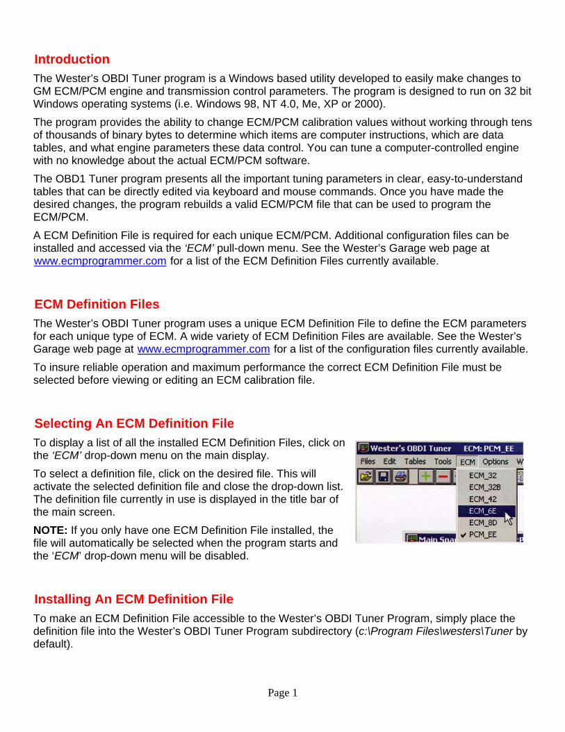
0BIntroduction The Wester’s OBDI Tuner program is a Windows based utility developed to easily make changes to GM ECM/PCM engine and transmission control parameters. The program is designed to run on 32 bit Windows operating systems (i.e. Windows 98, NT 4.0, Me, XP or 2000). The program provides the ability to change ECM/PCM calibration values without working through tens of thousands of binary bytes to determine which items are computer instructions, which are data tables, and what engine parameters these data control. You can tune a computer-controlled engine with no knowledge about the actual ECM/PCM software. The OBD1 Tuner program presents all the important tuning parameters in clear, easy-to-understand tables that can be directly edited via keyboard and mouse commands. Once you have made the desired changes, the program rebuilds a valid ECM/PCM file that can be used to program the ECM/PCM. A ECM Definition File is required for each unique ECM/PCM. Additional configuration files can be installed and accessed via the ‘ECM’ pull-down menu. See the Wester’s Garage web page at Uwww.ecmprogrammer.comU for a list of the ECM Definition Files currently available.
1BECM Definition Files The Wester’s OBDI Tuner program uses a unique ECM Definition File to define the ECM parameters for each unique type of ECM. A wide variety of ECM Definition Files are available. See the Wester’s Garage web page at Uwww.ecmprogrammer.comU for a list of the configuration files currently available. To insure reliable operation and maximum performance the correct ECM Definition File must be selected before viewing or editing an ECM calibration file.
2BSelecting An ECM Definition File To display a list of all the installed ECM Definition Files, click on the ‘ECM’ drop-down menu on the main display. To select a definition file, click on the desired file. This will activate the selected definition file and close the drop-down list. The definition file currently in use is displayed in the title bar of the main screen. NOTE: If you only have one ECM Definition File installed, the file will automatically be selected when the program starts and the ‘ECM’ drop-down menu will be disabled.
3BInstalling An ECM Definition File To make an ECM Definition File accessible to the Wester’s OBDI Tuner Program, simply place the definition file into the Wester’s OBDI Tuner Program subdirectory (c:\Program Files\westers\Tuner by default).
Page 2
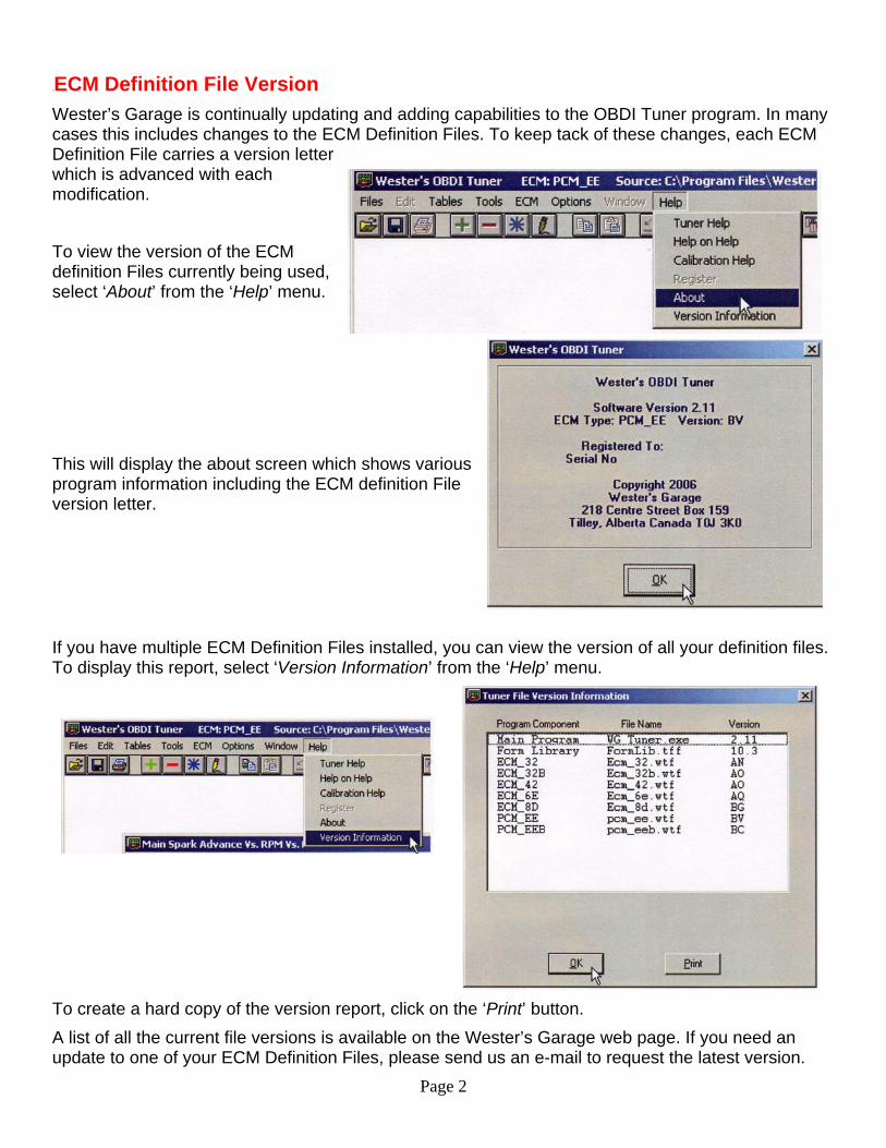
4BECM Definition File Version Wester’s Garage is continually updating and adding capabilities to the OBDI Tuner program. In many cases this includes changes to the ECM Definition Files. To keep tack of these changes, each ECM Definition File carries a version letter which is advanced with each modification. To view the version of the ECM definition Files currently being used, select ‘About’ from the ‘Help’ menu.
This will display the about screen which shows various program information including the ECM definition File version letter.
If you have multiple ECM Definition Files installed, you can view the version of all your definition files. To display this report, select ‘Version Information’ from the ‘Help’ menu.
To create a hard copy of the version report, click on the ‘Print’ button. A list of all the current file versions is available on the Wester’s Garage web page. If you need an update to one of your ECM Definition Files, please send us an e-mail to request the latest version.
Page 3
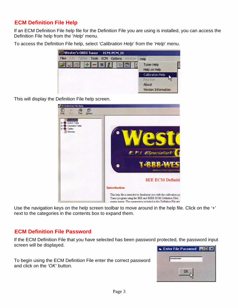
5BECM Definition File Help If an ECM Definition File help file for the Definition File you are using is installed, you can access the Definition File help from the ‘Help’ menu. To access the Definition File help, select ‘Calibration Help’ from the ‘Help’ menu.
This will display the Definition File help screen.
Use the navigation keys on the help screen toolbar to move around in the help file. Click on the ‘+’ next to the categories in the contents box to expand them.
6BECM Definition File Password If the ECM Definition File that you have selected has been password protected, the password input screen will be displayed.
To begin using the ECM Definition File enter the correct password and click on the ‘OK’ button.
Page 4
7BECM Calibration Files An ECM calibration file is a binary format file created by reading the EPROM from your vehicle’s ECM. This is accomplished using an appropriate EPROM programming device. UTo be compatible with the Wester’s OBDI Tuner Program, the ECM Calibration File, must be saved in binary format with the .BIN file extension. In the case of the FLASH PCM’s supported by the $EE ECM Definition File, the program will also accept .lt1 format files.
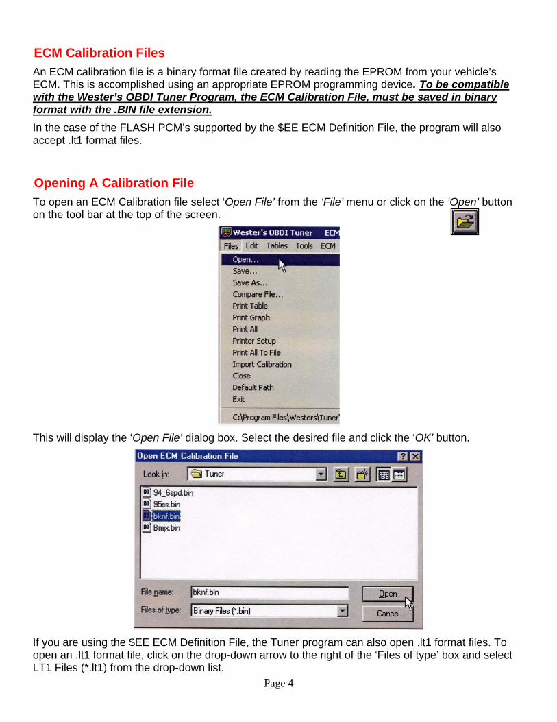
8BOpening A Calibration File To open an ECM Calibration file select ‘Open File’ from the ‘File’ menu or click on the ‘Open’ button on the tool bar at the top of the screen.
This will display the ‘Open File’ dialog box. Select the desired file and click the ‘OK’ button.
If you are using the $EE ECM Definition File, the Tuner program can also open .lt1 format files. To open an .lt1 format file, click on the drop-down arrow to the right of the ‘Files of type’ box and select LT1 Files (*.lt1) from the drop-down list.
Page 5
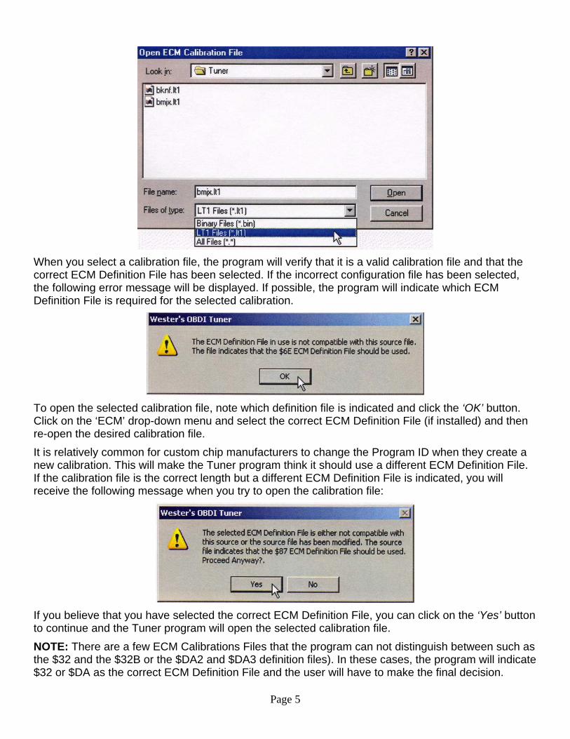
When you select a calibration file, the program will verify that it is a valid calibration file and that the correct ECM Definition File has been selected. If the incorrect configuration file has been selected, the following error message will be displayed. If possible, the program will indicate which ECM Definition File is required for the selected calibration.
To open the selected calibration file, note which definition file is indicated and click the ‘OK’ button. Click on the ‘ECM’ drop-down menu and select the correct ECM Definition File (if installed) and then re-open the desired calibration file. It is relatively common for custom chip manufacturers to change the Program ID when they create a new calibration. This will make the Tuner program think it should use a different ECM Definition File. If the calibration file is the correct length but a different ECM Definition File is indicated, you will receive the following message when you try to open the calibration file:
If you believe that you have selected the correct ECM Definition File, you can click on the ‘Yes’ button to continue and the Tuner program will open the selected calibration file. NOTE: There are a few ECM Calibrations Files that the program can not distinguish between such as the $32 and the $32B or the $DA2 and $DA3 definition files). In these cases, the program will indicate $32 or $DA as the correct ECM Definition File and the user will have to make the final decision.
Page 6
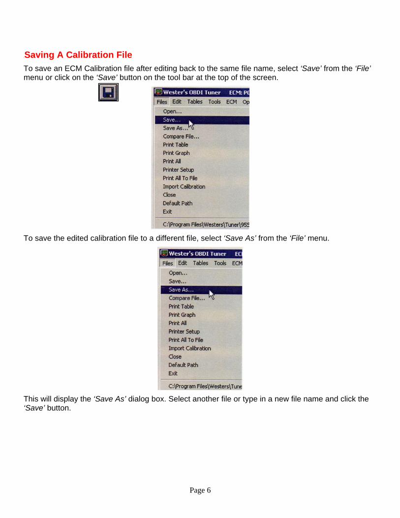
9BSaving A Calibration File To save an ECM Calibration file after editing back to the same file name, select ‘Save’ from the ‘File’ menu or click on the ‘Save’ button on the tool bar at the top of the screen.
To save the edited calibration file to a different file, select ‘Save As’ from the ‘File’ menu.
This will display the ‘Save As’ dialog box. Select another file or type in a new file name and click the ‘Save’ button.
Page 7
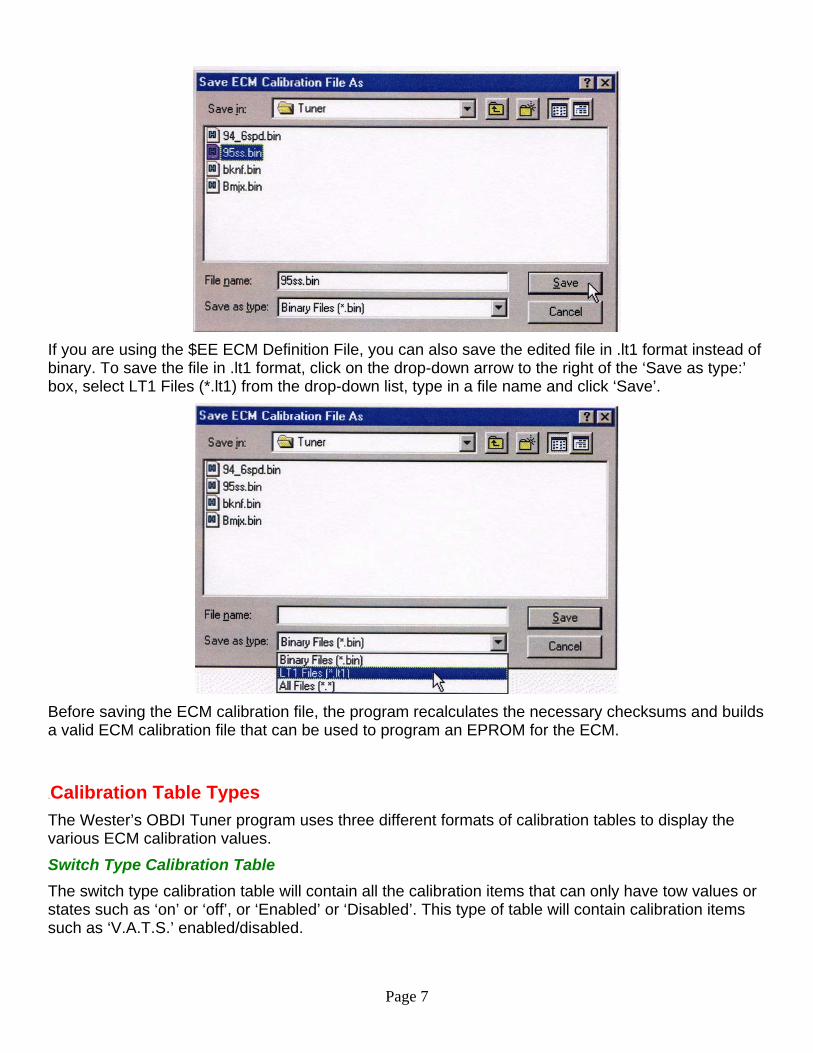
If you are using the $EE ECM Definition File, you can also save the edited file in .lt1 format instead of binary. To save the file in .lt1 format, click on the drop-down arrow to the right of the ‘Save as type:’ box, select LT1 Files (*.lt1) from the drop-down list, type in a file name and click ‘Save’.
Before saving the ECM calibration file, the program recalculates the necessary checksums and builds a valid ECM calibration file that can be used to program an EPROM for the ECM.
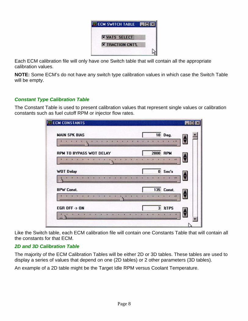
10BCalibration Table Types The Wester’s OBDI Tuner program uses three different formats of calibration tables to display the various ECM calibration values. Switch Type Calibration Table The switch type calibration table will contain all the calibration items that can only have tow values or states such as ‘on’ or ‘off’, or ‘Enabled’ or ‘Disabled’. This type of table will contain calibration items such as ‘V.A.T.S.’ enabled/disabled.
Page 8
Each ECM calibration file will only have one Switch table that will contain all the appropriate calibration values. NOTE: Some ECM’s do not have any switch type calibration values in which case the Switch Table will be empty. Constant Type Calibration Table The Constant Table is used to present calibration values that represent single values or calibration constants such as fuel cutoff RPM or injector flow rates.
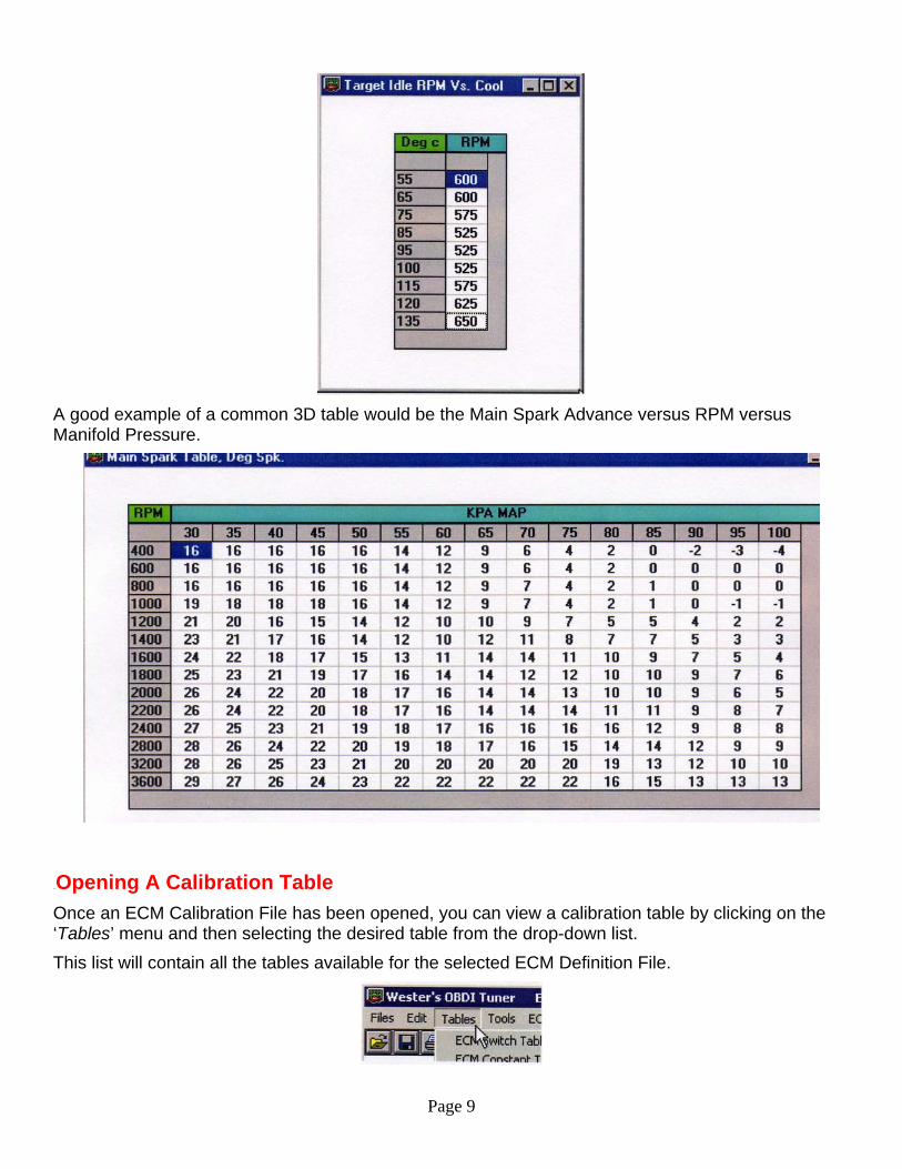
Like the Switch table, each ECM calibration file will contain one Constants Table that will contain all the constants for that ECM. 2D and 3D Calibration Table The majority of the ECM Calibration Tables will be either 2D or 3D tables. These tables are used to display a series of values that depend on one (2D tables) or 2 other parameters (3D tables). An example of a 2D table might be the Target Idle RPM versus Coolant Temperature.
Page 9
A good example of a common 3D table would be the Main Spark Advance versus RPM versus Manifold Pressure.
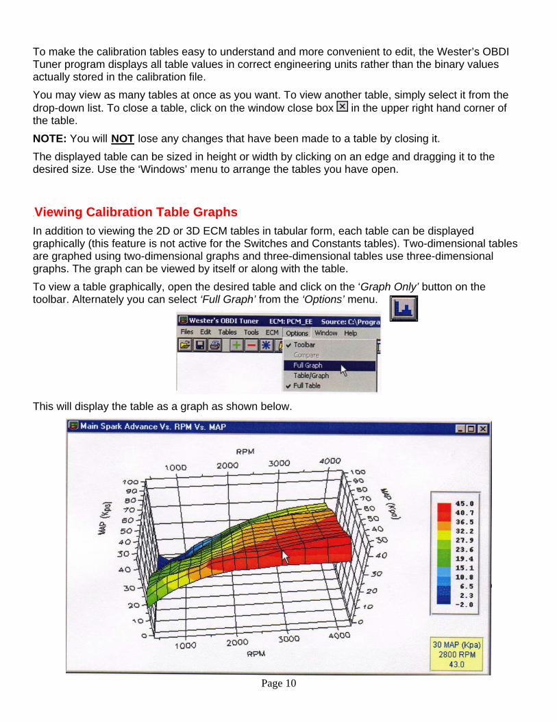
11BOpening A Calibration Table Once an ECM Calibration File has been opened, you can view a calibration table by clicking on the ‘Tables’ menu and then selecting the desired table from the drop-down list. This list will contain all the tables available for the selected ECM Definition File.
To make the calibration tables easy to understand and more convenient to edit, the Wester’s OBDI Tuner program displays all table values in correct engineering units rather than the binary values actually stored in the calibration file. You may view as many tables at once as you want. To view another table, simply select it from the drop-down list. To close a table, click on the window close box in the upper right hand corner of the table. NOTE: You will UNOTU lose any changes that have been made to a table by closing it. The displayed table can be sized in height or width by clicking on an edge and dragging it to the desired size. Use the ‘Windows’ menu to arrange the tables you have open.
12BViewing Calibration Table Graphs In addition to viewing the 2D or 3D ECM tables in tabular form, each table can be displayed graphically (this feature is not active for the Switches and Constants tables). Two-dimensional tables are graphed using two-dimensional graphs and three-dimensional tables use three-dimensional graphs. The graph can be viewed by itself or along with the table. To view a table graphically, open the desired table and click on the ‘Graph Only’ button on the toolbar. Alternately you can select ‘Full Graph’ from the ‘Options’ menu.
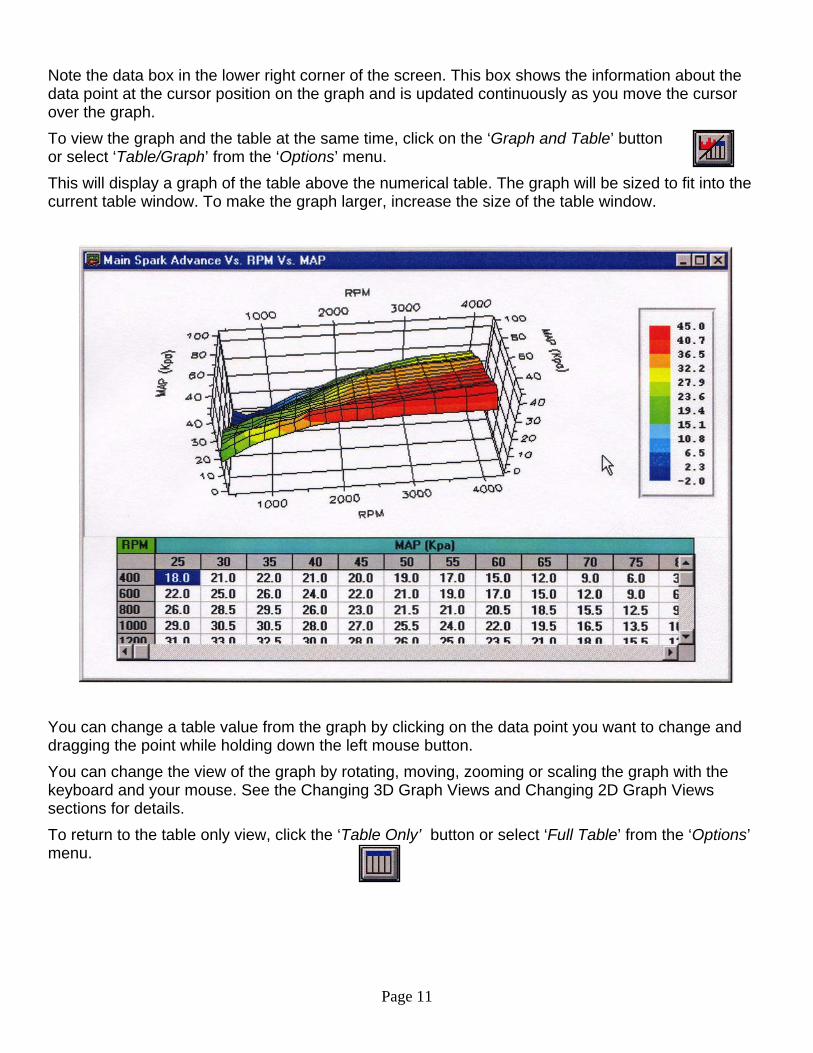
This will display the table as a graph as shown below.
Page 10
Page 11
Note the data box in the lower right corner of the screen. This box shows the information about the data point at the cursor position on the graph and is updated continuously as you move the cursor over the graph. To view the graph and the table at the same time, click on the ‘Graph and Table’ button or select ‘Table/Graph’ from the ‘Options’ menu. This will display a graph of the table above the numerical table. The graph will be sized to fit into the current table window. To make the graph larger, increase the size of the table window.
You can change a table value from the graph by clicking on the data point you want to change and dragging the point while holding down the left mouse button. You can change the view of the graph by rotating, moving, zooming or scaling the graph with the keyboard and your mouse. See the Changing 3D Graph Views and Changing 2D Graph Views sections for details. To return to the table only view, click the ‘Table Only’ button or select ‘Full Table’ from the ‘Options’ menu.
Page 12
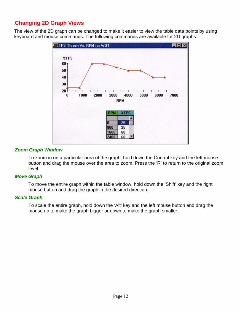
13BChanging 2D Graph Views The view of the 2D graph can be changed to make it easier to view the table data points by using keyboard and mouse commands. The following commands are available for 2D graphs:
43BZoom Graph Window
To zoom in on a particular area of the graph, hold down the Control key and the left mouse button and drag the mouse over the area to zoom. Press the ‘R’ to return to the original zoom level.
44BMove Graph To move the entire graph within the table window, hold down the ‘Shift’ key and the right mouse button and drag the graph in the desired direction.
45BScale Graph To scale the entire graph, hold down the ‘Alt’ key and the left mouse button and drag the mouse up to make the graph bigger or down to make the graph smaller.
Page 13
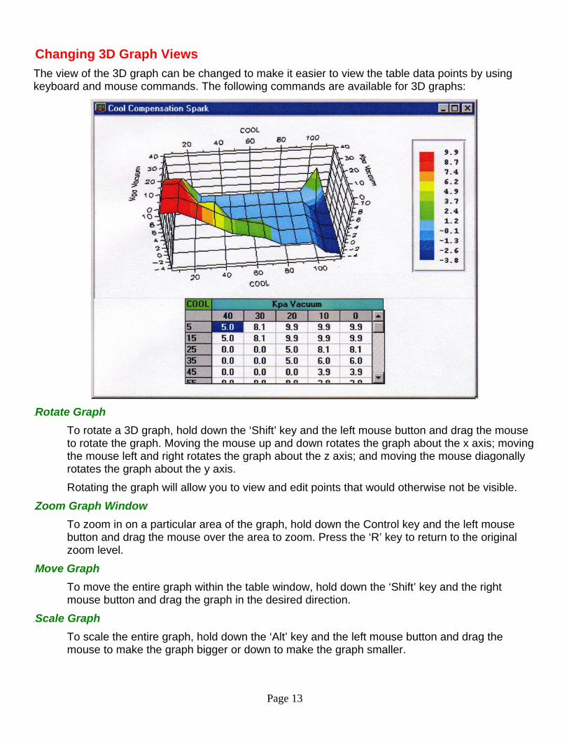
14BChanging 3D Graph Views The view of the 3D graph can be changed to make it easier to view the table data points by using keyboard and mouse commands. The following commands are available for 3D graphs:
46BRotate Graph
To rotate a 3D graph, hold down the ‘Shift’ key and the left mouse button and drag the mouse to rotate the graph. Moving the mouse up and down rotates the graph about the x axis; moving the mouse left and right rotates the graph about the z axis; and moving the mouse diagonally rotates the graph about the y axis. Rotating the graph will allow you to view and edit points that would otherwise not be visible.
47BZoom Graph Window To zoom in on a particular area of the graph, hold down the Control key and the left mouse button and drag the mouse over the area to zoom. Press the ‘R’ key to return to the original zoom level.
48BMove Graph To move the entire graph within the table window, hold down the ‘Shift’ key and the right mouse button and drag the graph in the desired direction.
49BScale Graph To scale the entire graph, hold down the ‘Alt’ key and the left mouse button and drag the mouse to make the graph bigger or down to make the graph smaller.
Page 14
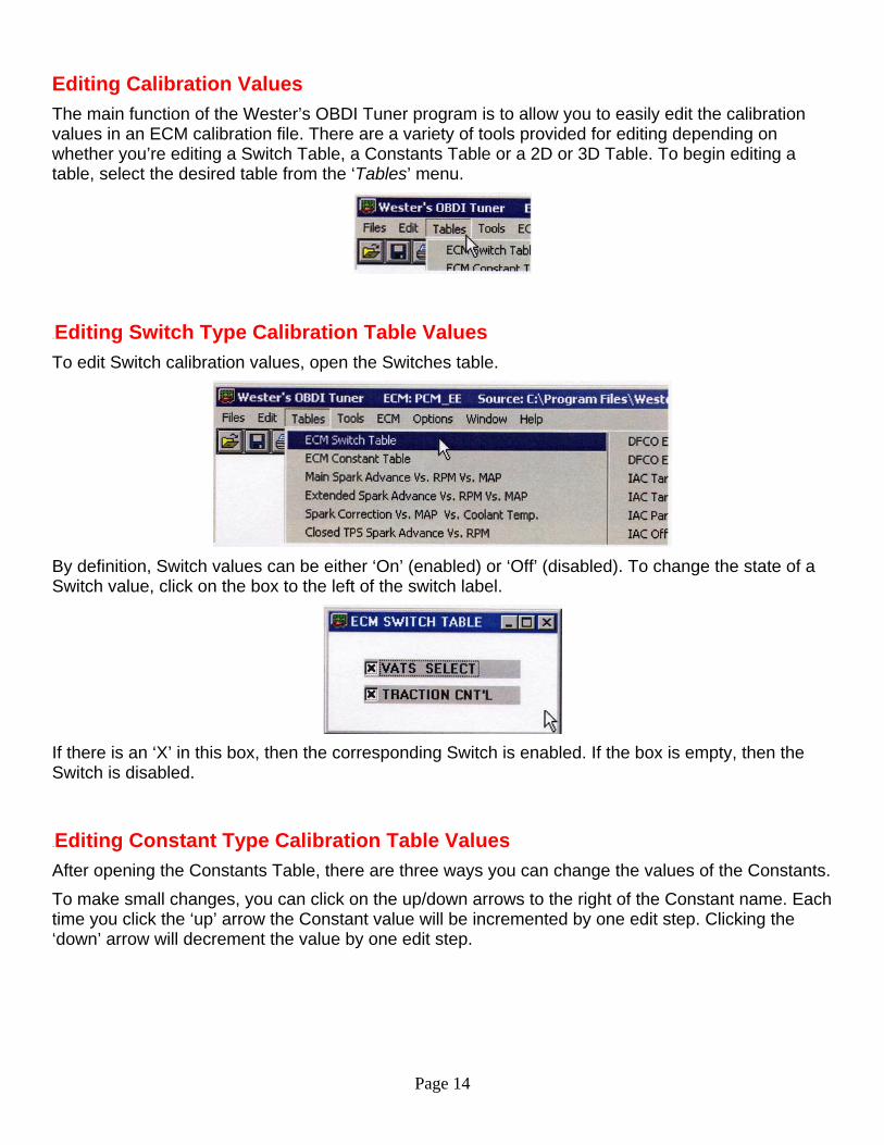
Editing Calibration Values The main function of the Wester’s OBDI Tuner program is to allow you to easily edit the calibration values in an ECM calibration file. There are a variety of tools provided for editing depending on whether you’re editing a Switch Table, a Constants Table or a 2D or 3D Table. To begin editing a table, select the desired table from the ‘Tables’ menu.
15BEditing Switch Type Calibration Table Values To edit Switch calibration values, open the Switches table.
By definition, Switch values can be either ‘On’ (enabled) or ‘Off’ (disabled). To change the state of a Switch value, click on the box to the left of the switch label.
If there is an ‘X’ in this box, then the corresponding Switch is enabled. If the box is empty, then the Switch is disabled.
16BEditing Constant Type Calibration Table Values After opening the Constants Table, there are three ways you can change the values of the Constants. To make small changes, you can click on the up/down arrows to the right of the Constant name. Each time you click the ‘up’ arrow the Constant value will be incremented by one edit step. Clicking the ‘down’ arrow will decrement the value by one edit step.
Page 15
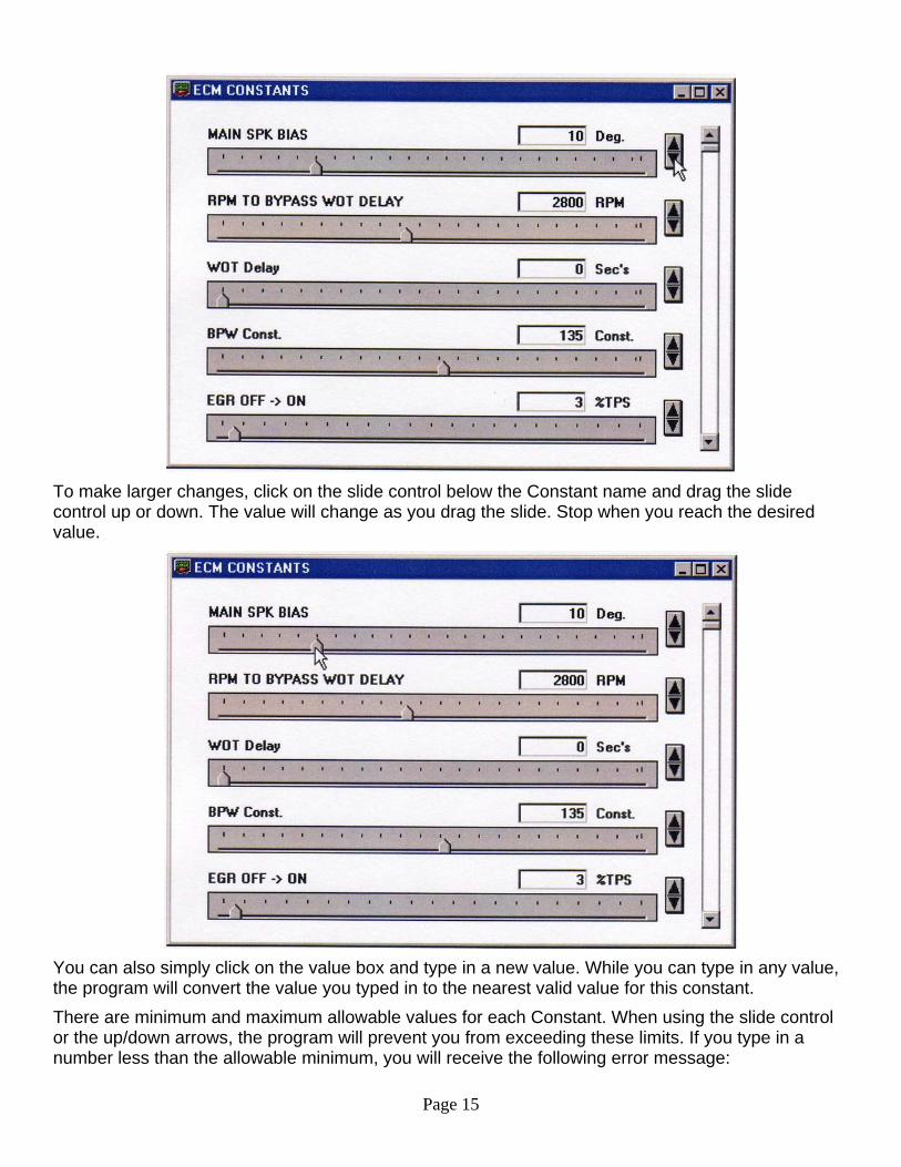
To make larger changes, click on the slide control below the Constant name and drag the slide control up or down. The value will change as you drag the slide. Stop when you reach the desired value.
You can also simply click on the value box and type in a new value. While you can type in any value, the program will convert the value you typed in to the nearest valid value for this constant. There are minimum and maximum allowable values for each Constant. When using the slide control or the up/down arrows, the program will prevent you from exceeding these limits. If you type in a number less than the allowable minimum, you will receive the following error message:

Page 16
To use the minimum allowable value, click ‘OK’. Click ‘Cancel’ to return to the previous value. Similarly, if you type in a value greater than the allowable maximum, you will receive an error message that will ask you if you would like to use the maximum allowable value.
Selecting 2D and 3D Table Cells To edit values in the tables, you must first select the cell or cells containing the values to be changed. To select a single table cell, simply click on the desired cell with the left mouse button. To select a range of cells, click on the first cell with the left mouse button and drag the mouse while holding down the left mouse button to highlight the desired range of cells.
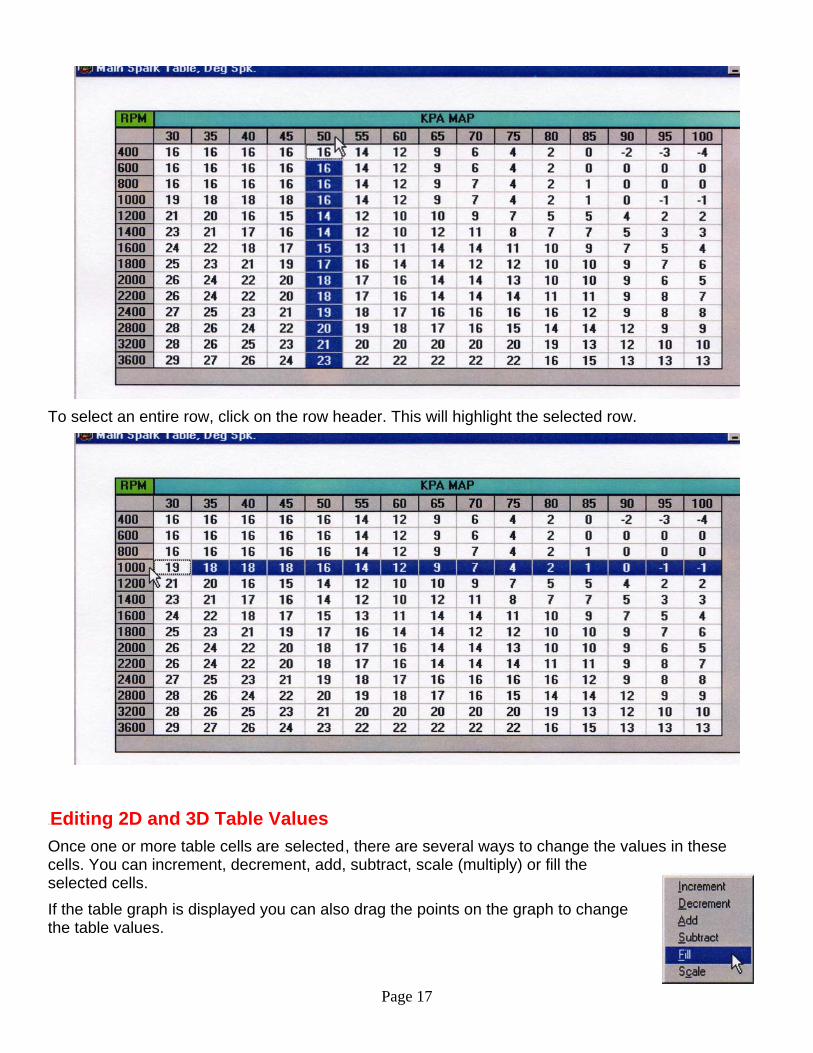
To select an entire column, click on the column heading with the left mouse button. The selected column will be highlighted.
Page 17
To select an entire row, click on the row header. This will highlight the selected row.
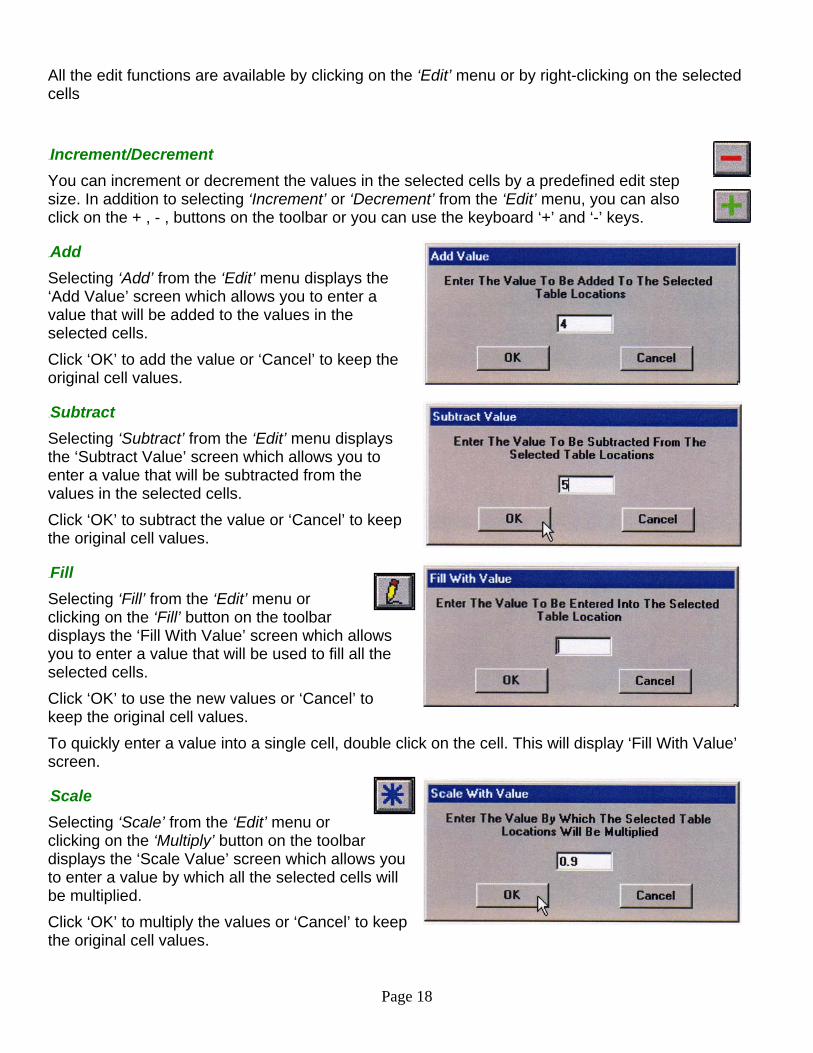
17BEditing 2D and 3D Table Values Once one or more table cells are HselectedH, there are several ways to change the values in these cells. You can increment, decrement, add, subtract, scale (multiply) or fill the selected cells. If the table graph is displayed you can also drag the points on the graph to change the table values.
Page 18
All the edit functions are available by clicking on the ‘Edit’ menu or by right-clicking on the selected cells
50BIncrement/Decrement You can increment or decrement the values in the selected cells by a predefined edit step size. In addition to selecting ‘Increment’ or ‘Decrement’ from the ‘Edit’ menu, you can also click on the + , - , buttons on the toolbar or you can use the keyboard ‘+’ and ‘-’ keys.
51BAdd Selecting ‘Add’ from the ‘Edit’ menu displays the ‘Add Value’ screen which allows you to enter a value that will be added to the values in the selected cells. Click ‘OK’ to add the value or ‘Cancel’ to keep the original cell values.
52BSubtract Selecting ‘Subtract’ from the ‘Edit’ menu displays the ‘Subtract Value’ screen which allows you to enter a value that will be subtracted from the values in the selected cells. Click ‘OK’ to subtract the value or ‘Cancel’ to keep the original cell values.
53BFill Selecting ‘Fill’ from the ‘Edit’ menu or clicking on the ‘Fill’ button on the toolbar displays the ‘Fill With Value’ screen which allows you to enter a value that will be used to fill all the selected cells. Click ‘OK’ to use the new values or ‘Cancel’ to keep the original cell values. To quickly enter a value into a single cell, double click on the cell. This will display ‘Fill With Value’ screen.
54BScale Selecting ‘Scale’ from the ‘Edit’ menu or clicking on the ‘Multiply’ button on the toolbar displays the ‘Scale Value’ screen which allows you to enter a value by which all the selected cells will be multiplied. Click ‘OK’ to multiply the values or ‘Cancel’ to keep the original cell values.
Page 19
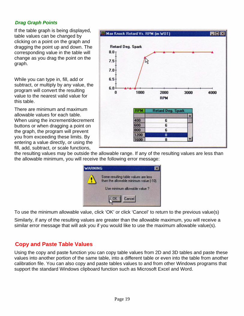
55BDrag Graph Points If the table graph is being displayed, table values can be changed by clicking on a point on the graph and dragging the point up and down. The corresponding value in the table will change as you drag the point on the graph.
While you can type in, fill, add or subtract, or multiply by any value, the program will convert the resulting value to the nearest valid value for this table. There are minimum and maximum allowable values for each table. When using the increment/decrement buttons or when dragging a point on the graph, the program will prevent you from exceeding these limits. By entering a value directly, or using the fill, add, subtract, or scale functions, the resulting values may be outside the allowable range. If any of the resulting values are less than the allowable minimum, you will receive the following error message:
To use the minimum allowable value, click ‘OK’ or click ‘Cancel’ to return to the previous value(s) Similarly, if any of the resulting values are greater than the allowable maximum, you will receive a similar error message that will ask you if you would like to use the maximum allowable value(s).
18BCopy and Paste Table Values Using the copy and paste function you can copy table values from 2D and 3D tables and paste these values into another portion of the same table, into a different table or even into the table from another calibration file. You can also copy and paste tables values to and from other Windows programs that support the standard Windows clipboard function such as Microsoft Excel and Word.
Page 20
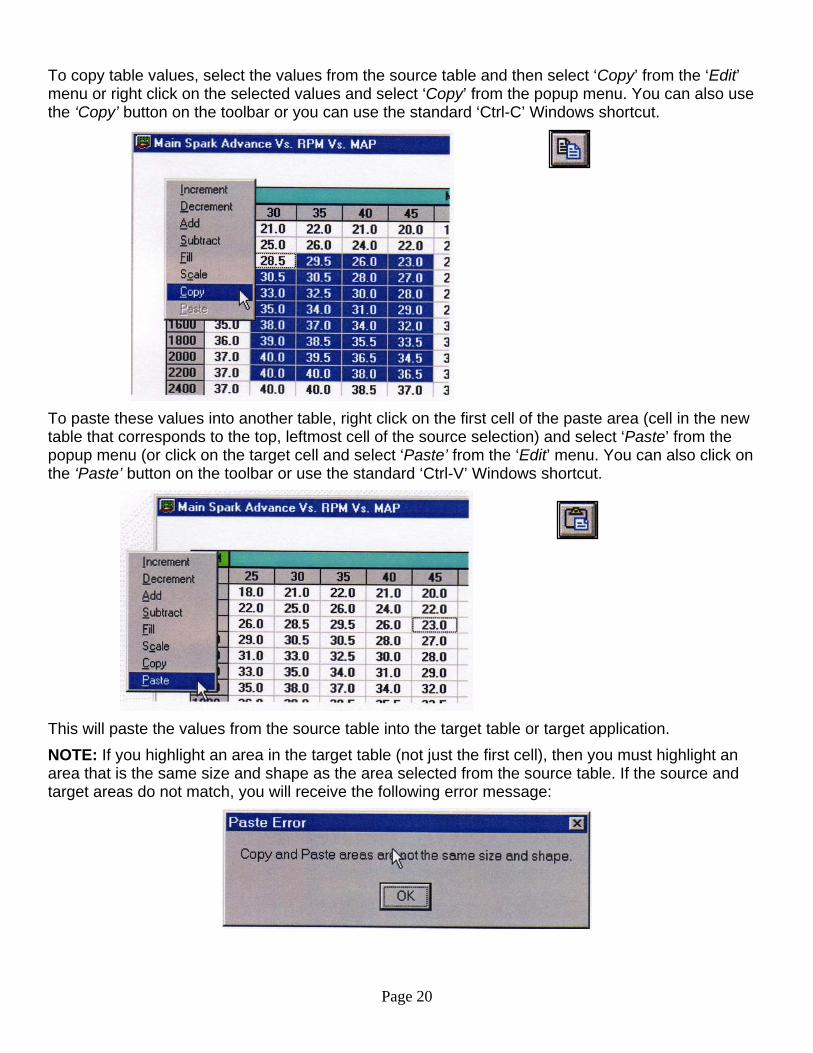
To copy table values, select the values from the source table and then select ‘Copy’ from the ‘Edit’ menu or right click on the selected values and select ‘Copy’ from the popup menu. You can also use the ‘Copy’ button on the toolbar or you can use the standard ‘Ctrl-C’ Windows shortcut.
To paste these values into another table, right click on the first cell of the paste area (cell in the new table that corresponds to the top, leftmost cell of the source selection) and select ‘Paste’ from the popup menu (or click on the target cell and select ‘Paste’ from the ‘Edit’ menu. You can also click on the ‘Paste’ button on the toolbar or use the standard ‘Ctrl-V’ Windows shortcut.
This will paste the values from the source table into the target table or target application. NOTE: If you highlight an area in the target table (not just the first cell), then you must highlight an area that is the same size and shape as the area selected from the source table. If the source and target areas do not match, you will receive the following error message:
Page 21
Similarly, if you select a start cell in the target table that does not allow the same number of cells to the left of and down from the start cell (i.e. target table not big enough), you will receive this same error message.
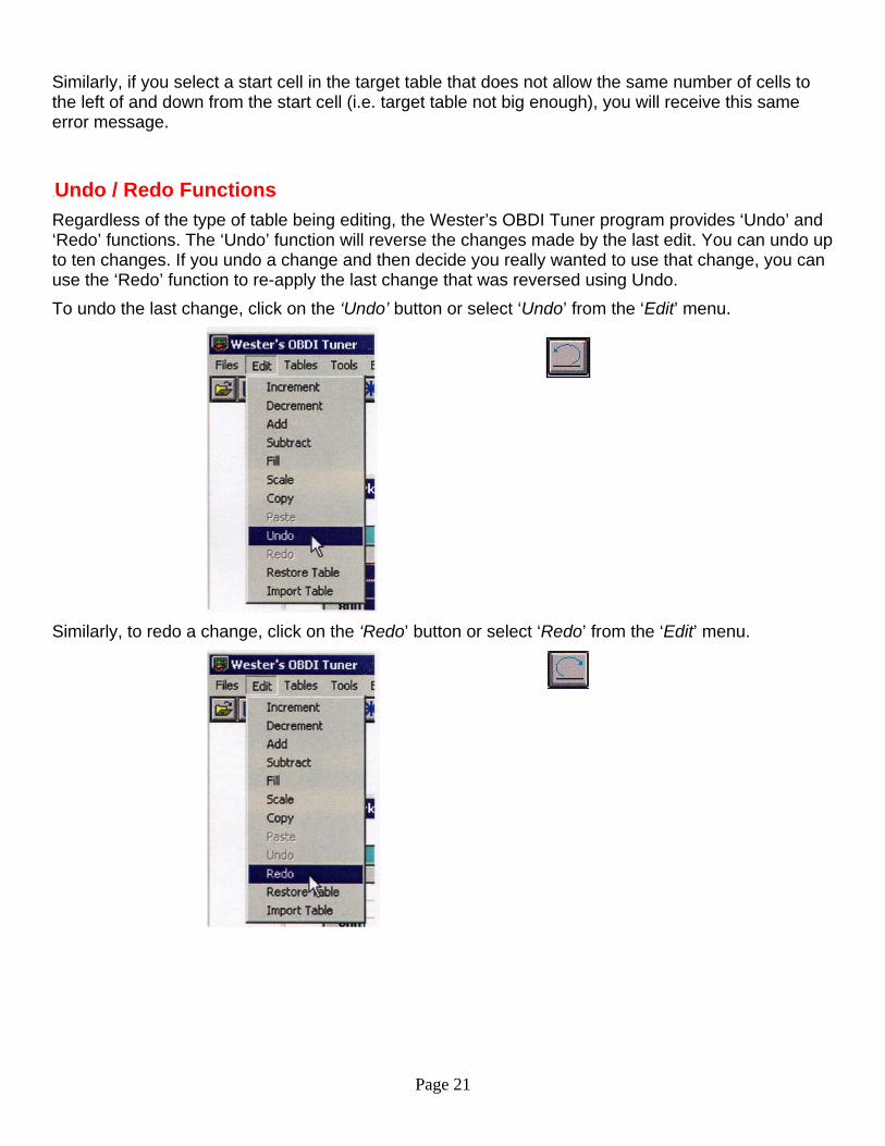
19BUndo / Redo Functions Regardless of the type of table being editing, the Wester’s OBDI Tuner program provides ‘Undo’ and ‘Redo’ functions. The ‘Undo’ function will reverse the changes made by the last edit. You can undo up to ten changes. If you undo a change and then decide you really wanted to use that change, you can use the ‘Redo’ function to re-apply the last change that was reversed using Undo. To undo the last change, click on the ‘Undo’ button or select ‘Undo’ from the ‘Edit’ menu.
Similarly, to redo a change, click on the ‘Redo’ button or select ‘Redo’ from the ‘Edit’ menu.
Page 22
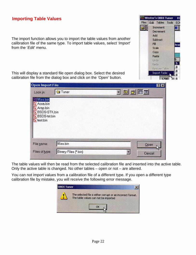
20BImporting Table Values The import function allows you to import the table values from another calibration file of the same type. To import table values, select ‘Import’ from the ‘Edit’ menu. This will display a standard file open dialog box. Select the desired calibration file from the dialog box and click on the ‘Open’ button.
The table values will then be read from the selected calibration file and inserted into the active table. Only the active table is changed. No other tables – open or not – are altered. You can not import values from a calibration file of a different type. If you open a different type calibration file by mistake, you will receive the following error message.
Page 23
21BRestore Table Values If you make several changes to table values and decide that you do not want to keep any of these changes, you can restore the table values to the Ulast savedU values using the Restore Table function. To restore the values in a table, select ‘Restore Table’ from the ‘Edit’ menu. This will restore the table values to the values that were in the table when you last saved the calibration file to disk. Only the active table is affected.
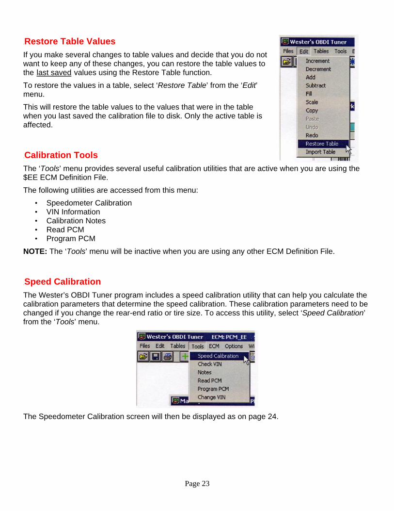
22BCalibration Tools The ‘Tools’ menu provides several useful calibration utilities that are active when you are using the $EE ECM Definition File. The following utilities are accessed from this menu:
• Speedometer Calibration • VIN Information • Calibration Notes • Read PCM • Program PCM
NOTE: The ‘Tools’ menu will be inactive when you are using any other ECM Definition File.
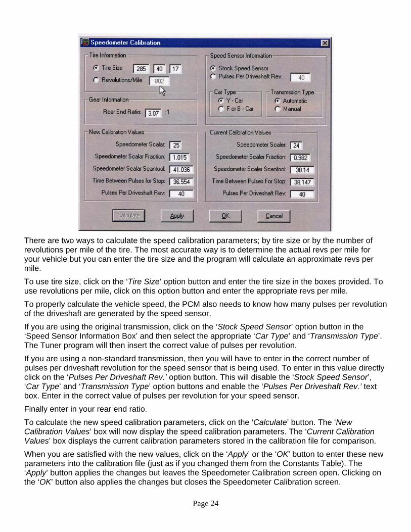
23BSpeed Calibration The Wester’s OBDI Tuner program includes a speed calibration utility that can help you calculate the calibration parameters that determine the speed calibration. These calibration parameters need to be changed if you change the rear-end ratio or tire size. To access this utility, select ‘Speed Calibration’ from the ‘Tools’ menu.
The Speedometer Calibration screen will then be displayed as on page 24.
Page 24
There are two ways to calculate the speed calibration parameters; by tire size or by the number of revolutions per mile of the tire. The most accurate way is to determine the actual revs per mile for your vehicle but you can enter the tire size and the program will calculate an approximate revs per mile. To use tire size, click on the ‘Tire Size’ option button and enter the tire size in the boxes provided. To use revolutions per mile, click on this option button and enter the appropriate revs per mile. To properly calculate the vehicle speed, the PCM also needs to know how many pulses per revolution of the driveshaft are generated by the speed sensor. If you are using the original transmission, click on the ‘Stock Speed Sensor’ option button in the ‘Speed Sensor Information Box’ and then select the appropriate ‘Car Type’ and ‘Transmission Type’. The Tuner program will then insert the correct value of pulses per revolution. If you are using a non-standard transmission, then you will have to enter in the correct number of pulses per driveshaft revolution for the speed sensor that is being used. To enter in this value directly click on the ‘Pulses Per Driveshaft Rev.’ option button. This will disable the ‘Stock Speed Sensor’, ‘Car Type’ and ‘Transmission Type’ option buttons and enable the ‘Pulses Per Driveshaft Rev.’ text box. Enter in the correct value of pulses per revolution for your speed sensor. Finally enter in your rear end ratio. To calculate the new speed calibration parameters, click on the ‘Calculate’ button. The ‘New Calibration Values’ box will now display the speed calibration parameters. The ‘Current Calibration Values’ box displays the current calibration parameters stored in the calibration file for comparison. When you are satisfied with the new values, click on the ‘Apply’ or the ‘OK’ button to enter these new parameters into the calibration file (just as if you changed them from the Constants Table). The ‘Apply’ button applies the changes but leaves the Speedometer Calibration screen open. Clicking on the ‘OK’ button also applies the changes but closes the Speedometer Calibration screen.
Page 25
Click on the ‘Cancel’ button to close the Speedometer Calibration screen without making any changes to the calibration file. If you use tire size, you should get close to the correct calibration values but you may have to make some corrections after testing. To fine tune the speedometer calibration further, use revs per mile to make small adjustments.
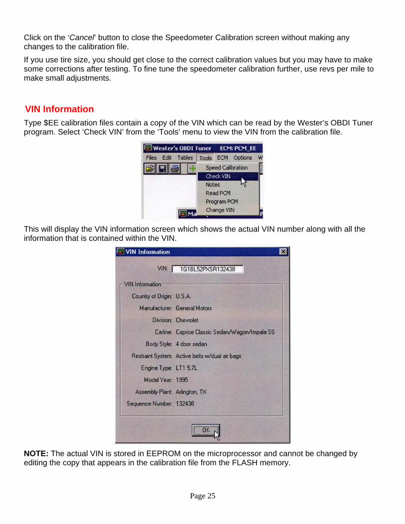
24BVIN Information Type $EE calibration files contain a copy of the VIN which can be read by the Wester’s OBDI Tuner program. Select ‘Check VIN’ from the ‘Tools’ menu to view the VIN from the calibration file.
This will display the VIN information screen which shows the actual VIN number along with all the information that is contained within the VIN.
NOTE: The actual VIN is stored in EEPROM on the microprocessor and cannot be changed by editing the copy that appears in the calibration file from the FLASH memory.
Page 26
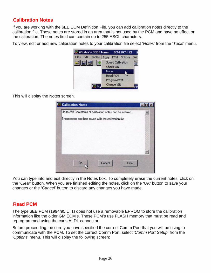
25BCalibration Notes If you are working with the $EE ECM Definition File, you can add calibration notes directly to the calibration file. These notes are stored in an area that is not used by the PCM and have no effect on the calibration. The notes field can contain up to 255 ASCII characters. To view, edit or add new calibration notes to your calibration file select ‘Notes’ from the ‘Tools’ menu.
This will display the Notes screen.
You can type into and edit directly in the Notes box. To completely erase the current notes, click on the ‘Clear’ button. When you are finished editing the notes, click on the ‘OK’ button to save your changes or the ‘Cancel’ button to discard any changes you have made.
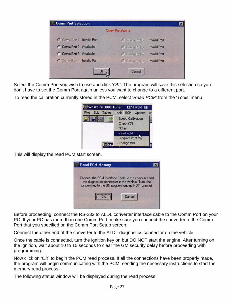
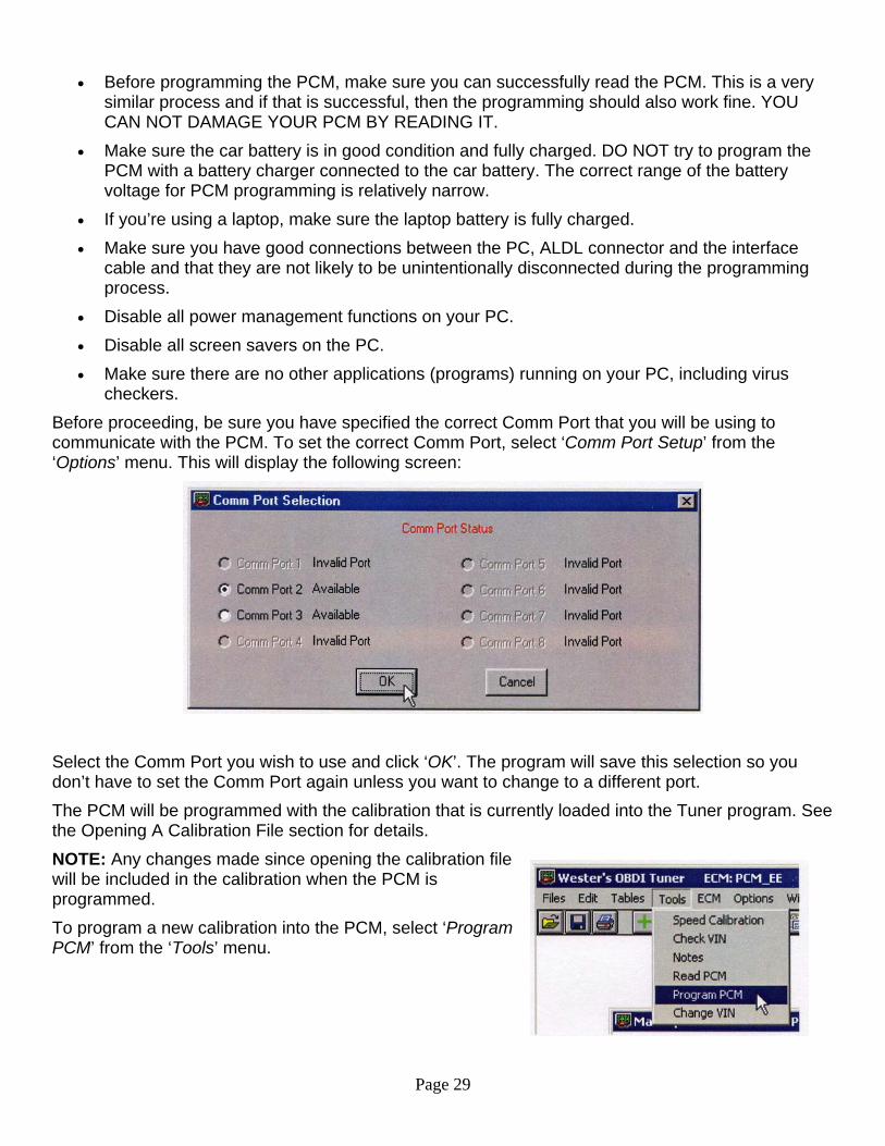
26BRead PCM The type $EE PCM (1994/95 LT1) does not use a removable EPROM to store the calibration information like the older GM ECM’s. These PCM’s use FLASH memory that must be read and reprogrammed using the car’s ALDL connector. Before proceeding, be sure you have specified the correct Comm Port that you will be using to communicate with the PCM. To set the correct Comm Port, select ‘Comm Port Setup’ from the ‘Options’ menu. This will display the following screen:
Page 27
Select the Comm Port you wish to use and click ‘OK’. The program will save this selection so you don’t have to set the Comm Port again unless you want to change to a different port. To read the calibration currently stored in the PCM, select ‘Read PCM’ from the ‘Tools’ menu.
This will display the read PCM start screen.
Before proceeding, connect the RS-232 to ALDL converter interface cable to the Comm Port on your PC. If your PC has more than one Comm Port, make sure you connect the converter to the Comm Port that you specified on the Comm Port Setup screen. Connect the other end of the converter to the ALDL diagnostics connector on the vehicle. Once the cable is connected, turn the ignition key on but DO NOT start the engine. After turning on the ignition, wait about 10 to 15 seconds to clear the GM security delay before proceeding with programming. Now click on ‘OK’ to begin the PCM read process. If all the connections have been properly made, the program will begin communicating with the PCM, sending the necessary instructions to start the memory read process. The following status window will be displayed during the read process:
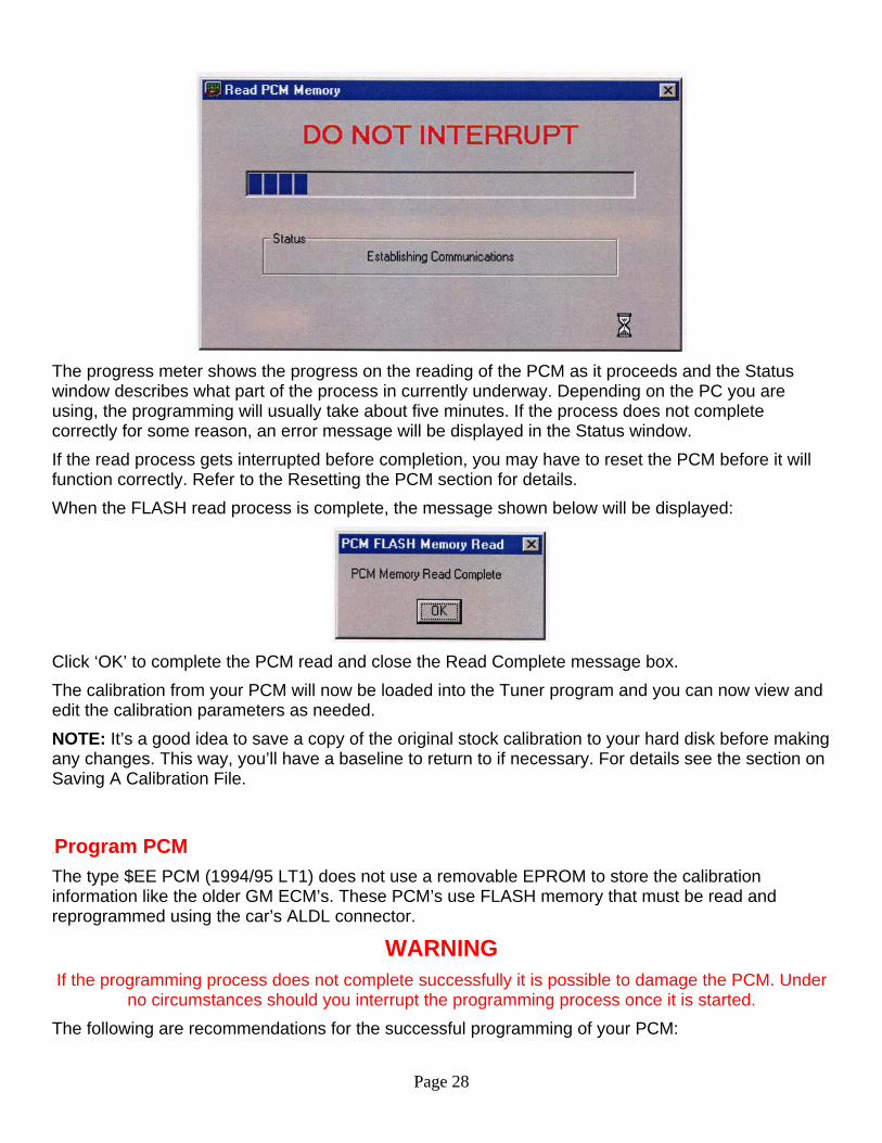
Page 28
The progress meter shows the progress on the reading of the PCM as it proceeds and the Status window describes what part of the process in currently underway. Depending on the PC you are using, the programming will usually take about five minutes. If the process does not complete correctly for some reason, an error message will be displayed in the Status window. If the read process gets interrupted before completion, you may have to reset the PCM before it will function correctly. Refer to the Resetting the PCM section for details. When the FLASH read process is complete, the message shown below will be displayed:
Click ‘OK’ to complete the PCM read and close the Read Complete message box. The calibration from your PCM will now be loaded into the Tuner program and you can now view and edit the calibration parameters as needed. NOTE: It’s a good idea to save a copy of the original stock calibration to your hard disk before making any changes. This way, you’ll have a baseline to return to if necessary. For details see the section on Saving A Calibration File.
27BProgram PCM The type $EE PCM (1994/95 LT1) does not use a removable EPROM to store the calibration information like the older GM ECM’s. These PCM’s use FLASH memory that must be read and reprogrammed using the car’s ALDL connector.
WARNING If the programming process does not complete successfully it is possible to damage the PCM. Under
no circumstances should you interrupt the programming process once it is started. The following are recommendations for the successful programming of your PCM:
Page 29
• Before programming the PCM, make sure you can successfully read the PCM. This is a very similar process and if that is successful, then the programming should also work fine. YOU CAN NOT DAMAGE YOUR PCM BY READING IT.
• Make sure the car battery is in good condition and fully charged. DO NOT try to program the PCM with a battery charger connected to the car battery. The correct range of the battery voltage for PCM programming is relatively narrow.
• If you’re using a laptop, make sure the laptop battery is fully charged. • Make sure you have good connections between the PC, ALDL connector and the interface
cable and that they are not likely to be unintentionally disconnected during the programming process.
• Disable all power management functions on your PC. • Disable all screen savers on the PC. • Make sure there are no other applications (programs) running on your PC, including virus
checkers. Before proceeding, be sure you have specified the correct Comm Port that you will be using to communicate with the PCM. To set the correct Comm Port, select ‘Comm Port Setup’ from the ‘Options’ menu. This will display the following screen:
Select the Comm Port you wish to use and click ‘OK’. The program will save this selection so you don’t have to set the Comm Port again unless you want to change to a different port. The PCM will be programmed with the calibration that is currently loaded into the Tuner program. See the Opening A Calibration File section for details. NOTE: Any changes made since opening the calibration file will be included in the calibration when the PCM is programmed. To program a new calibration into the PCM, select ‘Program PCM’ from the ‘Tools’ menu.
Page 30
This will display the Program PCM start screen.
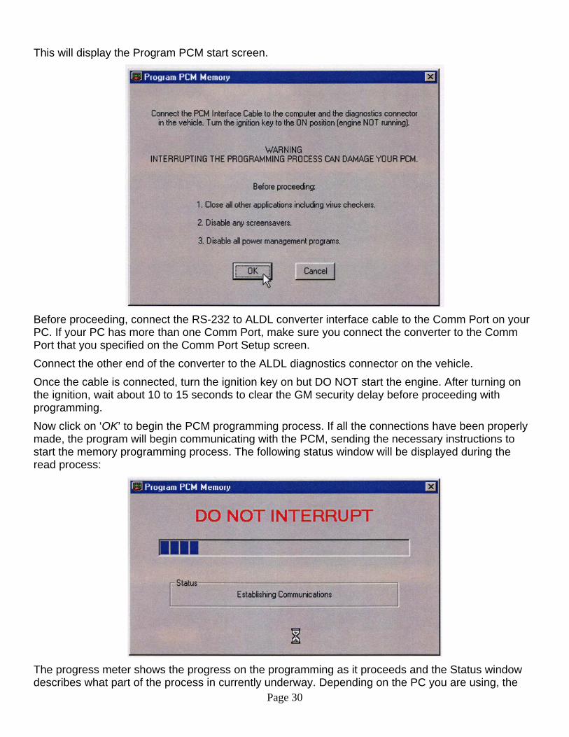
Before proceeding, connect the RS-232 to ALDL converter interface cable to the Comm Port on your PC. If your PC has more than one Comm Port, make sure you connect the converter to the Comm Port that you specified on the Comm Port Setup screen. Connect the other end of the converter to the ALDL diagnostics connector on the vehicle. Once the cable is connected, turn the ignition key on but DO NOT start the engine. After turning on the ignition, wait about 10 to 15 seconds to clear the GM security delay before proceeding with programming. Now click on ‘OK’ to begin the PCM programming process. If all the connections have been properly made, the program will begin communicating with the PCM, sending the necessary instructions to start the memory programming process. The following status window will be displayed during the read process:
The progress meter shows the progress on the programming as it proceeds and the Status window describes what part of the process in currently underway. Depending on the PC you are using, the
Page 31
programming will usually take about five minutes. If the process does not complete correctly for some reason, an error message will be displayed in the Status window. If the programming process gets interrupted before completion, you may be able to recover the PCM by resetting it. Refer to the Resetting the PCM section for details. When the FLASH programming process is complete, the message shown below will be displayed:
Click ‘OK’ to complete the PCM programming and close the Programming Complete message box. The calibration that was loaded into the Tuner program has now been transferred to the PCM and is ready for testing.
28BComparing ECM Calibration Files A unique and useful feature of the Wester’s OBDI Tuner program is the ability to compare two ECM calibration files. When the Compare function is enabled, the values in all tables will represent the difference between the primary ECM Calibration file and the Compare ECM Calibration File (primary file value – compare file value).
29BOpening A Compare ECM Calibration File To use the Compare function, you must open a Compare ECM Calibration file after opening your primary (the calibration file you are going to edit) ECM Calibration File.
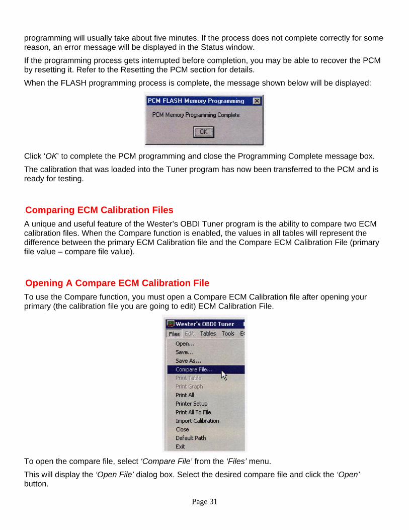
To open the compare file, select ‘Compare File’ from the ‘Files’ menu. This will display the ‘Open File’ dialog box. Select the desired compare file and click the ‘Open’ button.
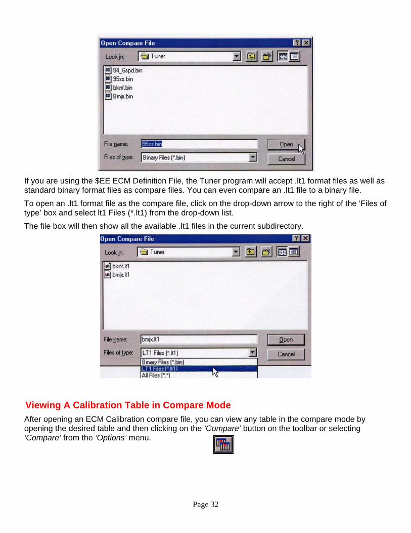
Page 32
If you are using the $EE ECM Definition File, the Tuner program will accept .lt1 format files as well as standard binary format files as compare files. You can even compare an .lt1 file to a binary file. To open an .lt1 format file as the compare file, click on the drop-down arrow to the right of the ‘Files of type’ box and select lt1 Files (*.lt1) from the drop-down list. The file box will then show all the available .lt1 files in the current subdirectory.
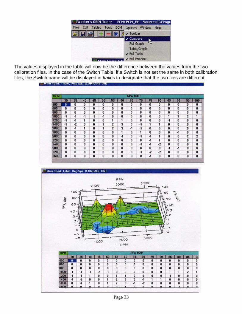
30BViewing A Calibration Table in Compare Mode After opening an ECM Calibration compare file, you can view any table in the compare mode by opening the desired table and then clicking on the ‘Compare’ button on the toolbar or selecting ‘Compare’ from the ‘Options’ menu.
Page 33
The values displayed in the table will now be the difference between the values from the two calibration files. In the case of the Switch Table, if a Switch is not set the same in both calibration files, the Switch name will be displayed in Italics to designate that the two files are different.
Page 34
If the table graph is displayed, the graph will show the differences as well. To switch back to normal view mode, click the ‘Compare’ button again. You can also edit the table values when in the Compare mode allowing you to see you changes relative to the Compare file. NOTE: When a table value is edited in the Compare mode, only the primary calibration value is being changed. UNo changes are made to the Compare Calibration fileU.
31BPrinting An ECM Calibration Table To print a calibration table, first open the table then either click on the ‘Print’ button on the toolbar or select ‘Print Table’ from the ‘Files’ menu. The selected table will be scaled to fit the page and printed as it appears on the screen.
32BPrinting An ECM Calibration Table Graph To print a 2D or 3D calibration table graph, display the graph and then select ‘Print Graph’ from the ‘Files’ menu. The selected table graph will be scaled to fit the page and printed as it appears on the display.
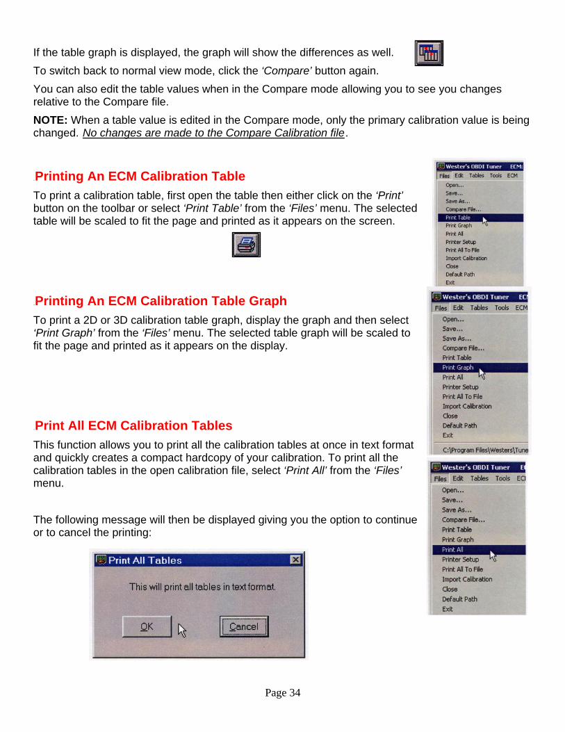
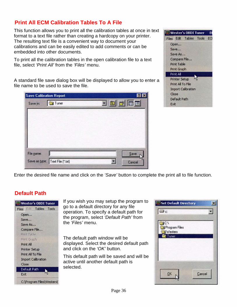
33BPrint All ECM Calibration Tables This function allows you to print all the calibration tables at once in text format and quickly creates a compact hardcopy of your calibration. To print all the calibration tables in the open calibration file, select ‘Print All’ from the ‘Files’ menu.
The following message will then be displayed giving you the option to continue or to cancel the printing:
Page 35
To continue with the printing click ‘OK’; to cancel the print click on the ‘Cancel’ button. All the calibration tables (including the Switch Table and the Constants Table) will be printed (as many tables per page as will fit) in text format similar to that shown below.
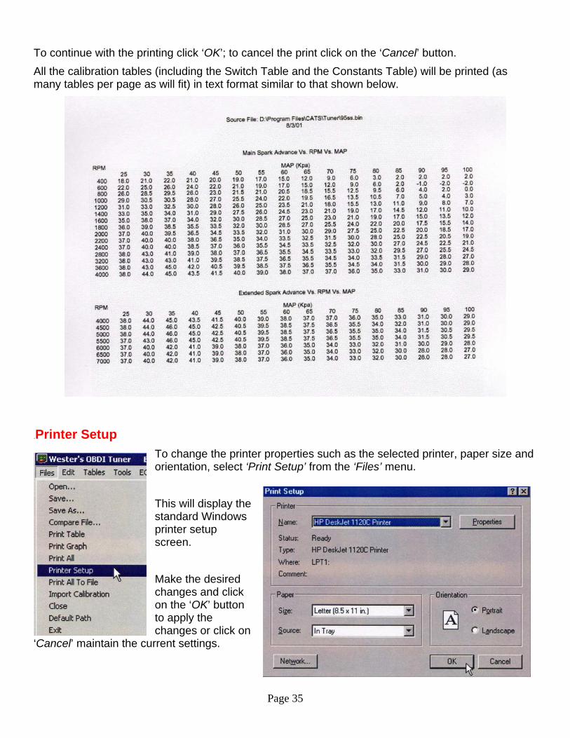
34BPrinter Setup To change the printer properties such as the selected printer, paper size and orientation, select ‘Print Setup’ from the ‘Files’ menu. This will display the standard Windows printer setup screen.
Make the desired changes and click on the ‘OK’ button to apply the changes or click on
‘Cancel’ maintain the current settings.
Page 36
35BPrint All ECM Calibration Tables To A File This function allows you to print all the calibration tables at once in text format to a text file rather than creating a hardcopy on your printer. The resulting text file is a convenient way to document your calibrations and can be easily edited to add comments or can be embedded into other documents. To print all the calibration tables in the open calibration file to a text file, select ‘Print All’ from the ‘Files’ menu.
A standard file save dialog box will be displayed to allow you to enter a file name to be used to save the file.
Enter the desired file name and click on the ‘Save’ button to complete the print all to file function.
36BDefault Path If you wish you may setup the program to go to a default directory for any file operation. To specify a default path for the program, select ‘Default Path’ from the ‘Files’ menu.
The default path window will be displayed. Select the desired default pathand click on the ‘OK
’ button.
This default path will be saved and will be active until another default path is selected.
Page 37
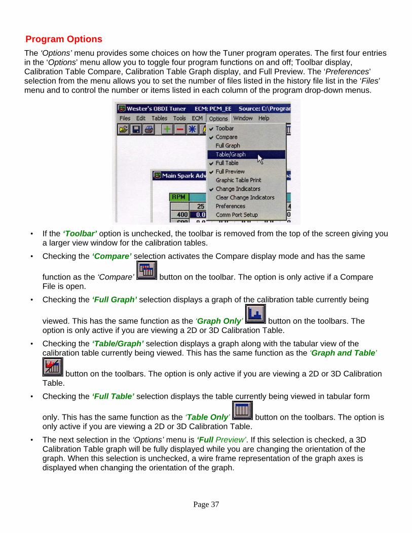
37BProgram Options The ‘Options’ menu provides some choices on how the Tuner program operates. The first four entries in the ‘Options’ menu allow you to toggle four program functions on and off; Toolbar display, Calibration Table Compare, Calibration Table Graph display, and Full Preview. The ‘Preferences’ selection from the menu allows you to set the number of files listed in the history file list in the ‘Files’ menu and to control the number or items listed in each column of the program drop-down menus.
• If the ‘Toolbar’ option is unchecked, the toolbar is removed from the top of the screen giving you
a larger view window for the calibration tables. • Checking the ‘Compare’ selection activates the Compare display mode and has the same
function as the ‘Compare’ button on the toolbar. The option is only active if a Compare File is open.
• Checking the ‘Full Graph’ selection displays a graph of the calibration table currently being
viewed. This has the same function as the ‘Graph Only’ button on the toolbars. The option is only active if you are viewing a 2D or 3D Calibration Table.
• Checking the ‘Table/Graph’ selection displays a graph along with the tabular view of the calibration table currently being viewed. This has the same function as the ‘Graph and Table’
button on the toolbars. The option is only active if you are viewing a 2D or 3D Calibration Table.
• Checking the ‘Full Table’ selection displays the table currently being viewed in tabular form
only. This has the same function as the ‘Table Only’ button on the toolbars. The option is only active if you are viewing a 2D or 3D Calibration Table.
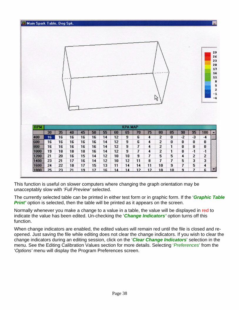
• The next selection in the ‘Options’ menu is ‘Full Preview’. If this selection is checked, a 3D Calibration Table graph will be fully displayed while you are changing the orientation of the graph. When this selection is unchecked, a wire frame representation of the graph axes is displayed when changing the orientation of the graph.
Page 38
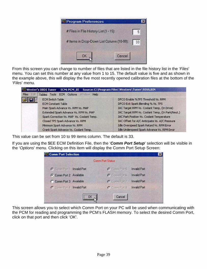
This function is useful on slower computers where changing the graph orientation may be unacceptably slow with ‘Full Preview’ selected. The currently selected table can be printed in either test form or in graphic form. If the ‘Graphic Table Print’ option is selected, then the table will be printed as it appears on the screen. Normally whenever you make a change to a value in a table, the value will be displayed in red to indicate the value has been edited. Un-checking the ‘Change Indicators’ option turns off this function. When change indicators are enabled, the edited values will remain red until the file is closed and re-opened. Just saving the file while editing does not clear the change indicators. If you wish to clear the change indicators during an editing session, click on the ‘Clear Change Indicators’ selection in the menu. See the Editing Calibration Values section for more details. Selecting ‘Preferences’ from the ‘Options’ menu will display the Program Preferences screen.
Page 39
From this screen you can change to number of files that are listed in the file history list in the ‘Files’ menu. You can set this number at any value from 1 to 15. The default value is five and as shown in the example above, this will display the five most recently opened calibration files at the bottom of the ‘Files’ menu.
This value can be set from 10 to 99 items column. The default is 33. If you are using the $EE ECM Definition File, then the ‘Comm Port Setup’ selection will be visible in the ‘Options’ menu. Clicking on this item will display the Comm Port Setup Screen:
This screen allows you to select which Comm Port on your PC will be used when communicating with the PCM for reading and programming the PCM’s FLASH memory. To select the desired Comm Port, click on that port and then click ‘OK’.
Page 40
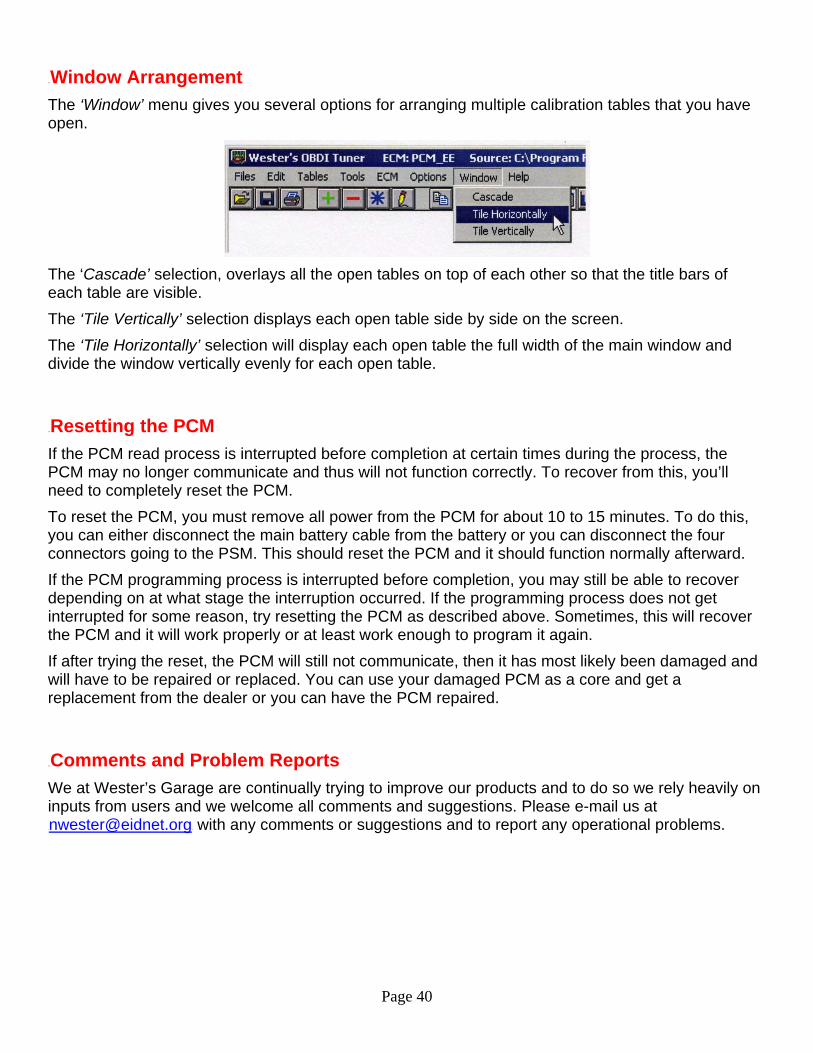
38BWindow Arrangement The ‘Window’ menu gives you several options for arranging multiple calibration tables that you have open.
The ‘Cascade’ selection, overlays all the open tables on top of each other so that the title bars of each table are visible. The ‘Tile Vertically’ selection displays each open table side by side on the screen. The ‘Tile Horizontally’ selection will display each open table the full width of the main window and divide the window vertically evenly for each open table.
39BResetting the PCM If the PCM read process is interrupted before completion at certain times during the process, the PCM may no longer communicate and thus will not function correctly. To recover from this, you’ll need to completely reset the PCM. To reset the PCM, you must remove all power from the PCM for about 10 to 15 minutes. To do this, you can either disconnect the main battery cable from the battery or you can disconnect the four connectors going to the PSM. This should reset the PCM and it should function normally afterward. If the PCM programming process is interrupted before completion, you may still be able to recover depending on at what stage the interruption occurred. If the programming process does not get interrupted for some reason, try resetting the PCM as described above. Sometimes, this will recover the PCM and it will work properly or at least work enough to program it again. If after trying the reset, the PCM will still not communicate, then it has most likely been damaged and will have to be repaired or replaced. You can use your damaged PCM as a core and get a replacement from the dealer or you can have the PCM repaired.
40BComments and Problem Reports We at Wester’s Garage are continually trying to improve our products and to do so we rely heavily on inputs from users and we welcome all comments and suggestions. Please e-mail us at [email protected] with any comments or suggestions and to report any operational problems.
Page 41
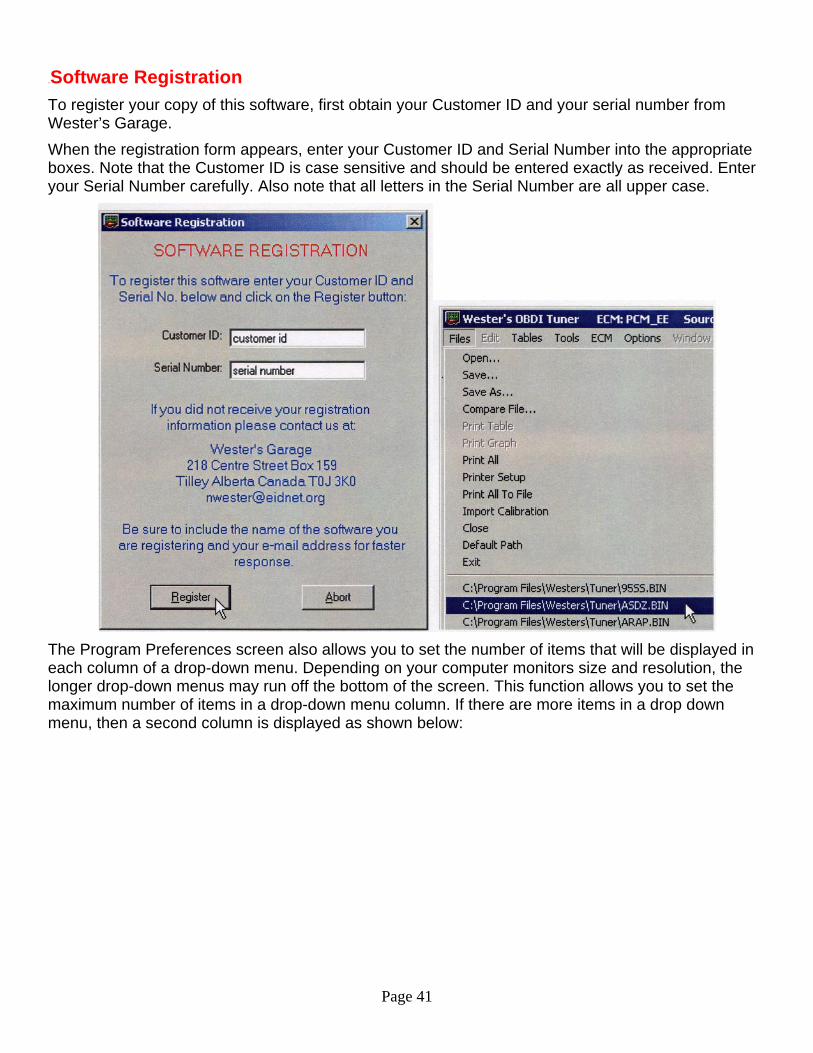
41BSoftware Registration To register your copy of this software, first obtain your Customer ID and your serial number from Wester’s Garage. When the registration form appears, enter your Customer ID and Serial Number into the appropriate boxes. Note that the Customer ID is case sensitive and should be entered exactly as received. Enter your Serial Number carefully. Also note that all letters in the Serial Number are all upper case.
The Program Preferences screen also allows you to set the number of items that will be displayed in each column of a drop-down menu. Depending on your computer monitors size and resolution, the longer drop-down menus may run off the bottom of the screen. This function allows you to set the maximum number of items in a drop-down menu column. If there are more items in a drop down menu, then a second column is displayed as shown below:

Page 42
42BSoftware License, Copyright And Warranty 56BCOPYRIGHT
The Wester’s OBDI Tuner software is copyright 2006 with all rights reserved. The distribution and sale of this software are for the exclusive use of the original purchaser for use exclusively on computers privately owned by that purchaser. Unauthorized copying, duplicating, selling, or otherwise distributing the software is in violation of the Federal Copyright Law.
57BLICENSE AGREEMENT Use of this product constitutes acceptance of these terms and conditions and an agreement to abide by them. This is a license agreement and not an agreement for sale. Wester’s Garage owns, or has licensed from the owner, copyrights in this software. The original purchaser is granted a personal, nonexclusive, non-transferable license to use this software under the terms stated in this agreement. You may not assign or transfer the software or this license without the express written consent of Wester’s Garage. Any attempt to sublicense, assign, or transfer any of the rights, duties, or obligations there under is void. You may not copy (except for backup purposes), modify, alter, electronically transfer, lease or rent the software. This license is in effect until terminated. You may terminate it at any time by destroying the software. It will also terminate if you fail to comply with any of the terms and conditions of this agreement. If the license terms are not acceptable, remove the software from your computer.
58BLIMITED WARRANTY AND DISCLAIMER Wester’s Garage warrants for a period of ninety (90) days from the date of delivery that the software, under normal use, will substantially perform as described in the documentation when used on the supported hardware and system software. Wester’s Garage’s entire liability and your exclusive remedy under this warranty will be at Wester’s Garage’s option, to attempt to correct or help you work around errors, replace the software with functionally equivalent software, or to refund the purchase price and terminate this Agreement. EXCEPT FOR PRIOR EXPRESS LIMITED WARRANTIES, WESTER’S GARAGE MAKES, AND YOU RECEIVE, NO WARRANTIES, EXPRESS, IMPLIED STATUTORY OR IN ANY COMMUNICATION WITH YOU, AND WESTER’S GARAGE SPECIFICALLY DISCLAIMS ANY IMPLIED WARRANTY OF MERCHANTABILITY OR FITNESS FOR A PARTICULAR PURPOSE. WESTER’S GARAGE DOES NOT WARRANT THAT THE OPERATION OF THE SOFTWARE WILL BE UNINTERRUPTED OR ERROR FREE.
59BLIMITATION OF LIABILITY IN NO EVENT WILL WESTER’S GARAGE BE LIABLE TO YOU FOR ANY DAMAGES, INCLUDING LOST PROFITS, LOST SAVINGS, OR OTHER INCIDENTAL OR CONSEQUENTIAL DAMAGES ARISING FROM THE USE OF THE SOFTWARE, EVEN IF WESTER’S GARAGE HAS BEEN ADVISED OF THE POSSIBILITY OF SUCH DAMAGES.
Copyright 2007 Westers Garage 1-888-WESTER-1