object recognition using a 3d rfid system
TRANSCRIPT

22
Object Recognition Using a 3D RFID System
Se-gon Roh and Hyouk Ryeol Choi School of Mechanical Engineering, Sungkyunkwan University,
Korea
1. Introduction
We cannot think about something if that something does not exist. If something exists, we can understand or imagine about it no matter what it may be. Understanding and imagination in this way fully depend on recognition. A human being’s object recognition is executed in real-time by identification intelligence, which is developed from experience, learning, and presumption. On the other hand, a robot’s object recognition is executed by sensation, perception, and identification. Sensation means the response to the stimulus and intensity of the object; for example, a vision system captures images obtained from a CCD camera (Weiss et al. 2001). Perception implies the estimation or acquirement of the object geometry, of which invariants are extracted from the two-dimensional luminance data. Identification matches and determines the object from a database based on the representations of the extracted geometry. These processes need to compute enormous data, so that real-time process is almost impossible. In addition, matching uncertainty is immanent in this recognition because the robot has much difficulty in identifying the existence of an object.
Fig. 1. Recognition for executing a task.
Suppose that a robot agent is commanded to clean the room as illustrated in Fig. 1. The robot has sensors such as ultrasonic, vision, and laser range finder. When executing the cleaning mission, it receives another order, that is, to bring the commander his/her mobile phone. Executing mission needs the classification of physical objects, which is to be kept or
� � � � � � � � �
� � � � � � � � � � � � � � � � � � � � � � �
� � � � � � � � � � � � � � � � � � � � � � � � � � � � � � � � � �
� � � � �
Ope
n A
cces
s D
atab
ase
ww
w.in
tech
web
.org
Source: Development and Implementation of RFID Technology, Book edited by: Cristina TURCU, ISBN 978-3-902613-54-7, pp. 554, February 2009, I-Tech, Vienna, Austria
www.intechopen.com

Development and Implementation of RFID Technology 414
cleaned. At the same time, it should find the mobile phone. However, sensors that should recognize objects for cleaning are beyond their computational capacity. Thus, the robot stops cleaning, and then begins to find the mobile phone. First, it scans all objects using vision, sonar, etc., and then will try to compare the objects with the target mobile phone. It, however, cannot find the target despite every effort because the sensors cannot scan the target object, which is hidden by bottles and a dish. Consequently, the robot cannot even confirm the existence of the target in the room and it will conclude that the target is in another room. RFID is an attractive technology to supplement the limitation of robot faculty. The basic but powerful function of this technology is to identify the existence of the object. In the same mission, there is another robot with the RFID system and all objects have built-in tags. This tag gives to the robot the information about the property or characteristic of the object. To clean the room, the robot easily chooses the objects, which should be removed or kept. To execute the second mission, the robot searches the ID lists of objects, which have been obtained while cleaning. Through this list, the robot has already knows that there is the target mobile phone in the room. To find the target, this robot moves to the position where the target has been detected, and then scans nearby objects using its sensors. Hence, the robot can complete its task more easily after object identification. The robot, however, does not know where the target is because the sensors cannot detect the target, which is hidden by other objects, and the mission is not completed. Obviously, the target is there, but something is often thought not to exist if it is not detected. Unfortunately, the RFID system also cannot present the solution for object recognition, because it is not enough to identify and confirm the existence of the object. In order to overcome this limitation, the authors have developed the advanced RFID system based on 3D tag. The proposed RFID system can identify the object, and estimate the object’s position and orientation. Because of these characteristics, the robot with the automated systems can recognize objects easily and rapidly. Naturally, this recognition mechanism can also simplify other robot processes such as localization, navigation, and manipulation. The authors have developed the algorithm and application of such processes based on the proposed RFID system. In this chapter, we mainly focus on the fundamental principle and algorithm of this system. In Section 2, the basic idea of this system is addressed. Sections 3 and 4 describe the structure of the system and the 3D tag, which characterize the system. The algorithms for estimating the position and orientation of the target object are given in Section 5, and experimental results are briefly presented in Section 6.
2. Problem statement and idea
An RFID system has been used for the artificial landmark to obtain the geographical information for navigation and localization of the mobile robot (Yamano et al, 2004; Kulyukin et al, 2004; Ni et al, 2003; Kubitz et al, 1997; Tsukiyama, 2002; Hahnel et al, 2004; Ruff & Hession, 2001). Using this system, several researchers have developed the application of RFID system to support object recognition and manipulation (Boukraa & Ando, 2002; Mae et al, 2000; Chong et al, 2004). Their studies are very useful and practical, in that, the RFID system supplements the limitation of the robot’s capability. Most of previous RFID systems have omni-directional read range. One RFID tag is embedded into one object, and this tag is detected by the antenna of the RFID system. This system informs the robot of the existence of an object. To recognize objects, however, a robot considerably depends on other sensors though it is equipped with the RFID system. For example, let us suppose the
www.intechopen.com
Object Recognition Using a 3D RFID System 415
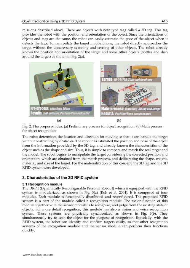
missions described above. There are objects with new type tags called a 3D tag. This tag provides the robot with the position and orientation of the object. Since the orientations of objects and tags are the same, the robot can easily estimate the pose of the object when it detects the tags. To manipulate the target mobile phone, the robot directly approaches the target without the unnecessary scanning and sensing of other objects. The robot already knows the position and orientation of the target and some other objects (bottles and dish around the target) as shown in Fig. 2(a).
(a) (b)
Fig. 2. The proposed Idea. (a) Preliminary process for object recognition. (b) Main process for object recognition.
The robot determines the location and direction for moving so that it can handle the target without obstructing by obstacles. The robot has estimated the position and pose of the object from the information provided by the 3D tag, and already known the characteristics of the object such as the shape and size. Thus, it is simple to compare and match the real target and the model. The robot begins to manipulate the target considering the corrected position and orientation, which are obtained from the match process, and deliberating the shape, weight, material, and size of the target. For the materialization of this concept, the 3D tag and the 3D RFID system were developed.
3. Characteristics of the 3D RFID system
3.1 Recognition module The DRP I (Dynamically Reconfigurable Personal Robot I) which is equipped with the RFID system is modularized, as shown in Fig. 3(a) (Roh et al, 2004). It is composed of four modules. Each module is functionally distributed and reconfigured. The proposed RFID system is a part of the module called a recognition module. The major function of this module together with the sensor module is to recognize, and judge from the existing state of objects. For more detail recognition, this module has also a vision and voice recognition system. These systems are physically synchronized as shown in Fig. 3(b). They simultaneously try to scan the object for the purpose of recognition. Especially, with the RFID system, the robot can identify and confirm targets easily, so that other recognition systems of the recognition module and the sensor module can perform their functions quickly.
�
�
�
�
�
��
�
�
�
�
� � �� �
� � ��
� � �� �
� � ��
� � � � � � � � � � � � � � � � � � � � � � � � � � � � � � � �
� � � � � � � � � � � � � � � � � � � � � � � � � � � � � � �
� � � � � � � � � � � ! " # $ � � � � � � � � � � � � � � � � � � � � � �
www.intechopen.com

Development and Implementation of RFID Technology 416
(a) (b)
Fig. 3. 3D RFID-based robot. (a) Modularization of robot. 1, 2, 3, and 4 represent recognition, arbiter, sensor, and mobile module, respectively. (b) Structure of recognition module.
3.2 Sensing range of the 3D RFID system The proposed RFID system is composed of an antenna and reader to detect the 3D tag (Roh et al, 2006). The antenna can be swept by the actuator in Fig. 3(b), and it has the uni-directional read range as shown in Fig. 4. These features are used for estimating the position and orientation of the 3D tag. The 3D tag is composed of several passive tags, which have the dipole antennas as shown in Fig. 4(b). It has no self-power source, so it has to obtain its required power through electromagnetic induction, especially magnetic field.
(a) (b) Fig. 4. RFID antenna and tag. (a) Simulated sensing range of the RFID antenna. (b)Tag with a small dipole antenna
� � � � � � � � �
� � � � � � � � � � � � � � � � �
� � � � � � � � � � � �
� � � � � � � �
� � � � � � � �
� � � � � � � � � � �
� � � � � � � � � � � �
� � �
� � �
� � �
� � � � � � � � � � � � � � � � � � � � � � � � � � � � �
� � � � � � � �
� � � � � � � � � � � � � � � � �� � � � � � � � � � � � � � � � �
� � � � � � � � � � � �
������
� � � � �
www.intechopen.com

Object Recognition Using a 3D RFID System 417
(a) (b)
(c) (d)
(e) (f)
Fig. 5. Read range pattern of the RFID antenna according to the height of the tag. (a) z=50mm. (b) z=250mm. (c) z=450mm. (d) z=650mm. (e) z=850mm. (f). z=950mmmm.
To induce sufficient operating voltage, the tag must be placed within the range of the detectable angle and distance in the magnetic field of the electromagnetic wave from the antenna. If the tag is out of the range of detectable angle, it cannot be sensed by the reader even if it is placed within the detectable distance. The specific detectable angle and distance
www.intechopen.com
Development and Implementation of RFID Technology 418
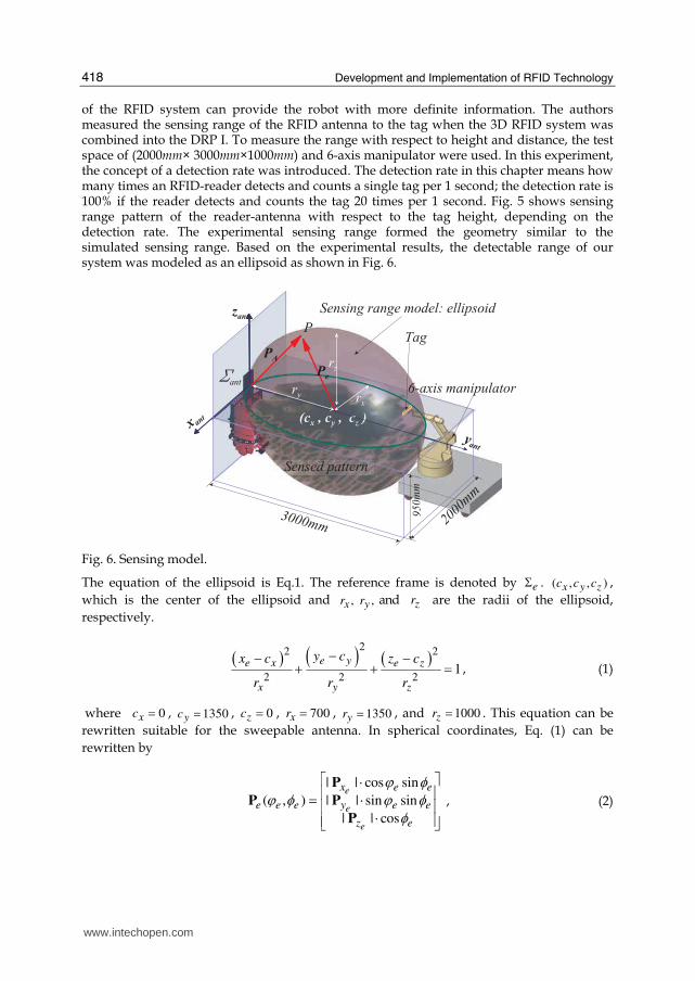
of the RFID system can provide the robot with more definite information. The authors measured the sensing range of the RFID antenna to the tag when the 3D RFID system was combined into the DRP I. To measure the range with respect to height and distance, the test space of (2000mm× 3000mm×1000mm) and 6-axis manipulator were used. In this experiment, the concept of a detection rate was introduced. The detection rate in this chapter means how many times an RFID-reader detects and counts a single tag per 1 second; the detection rate is 100% if the reader detects and counts the tag 20 times per 1 second. Fig. 5 shows sensing range pattern of the reader-antenna with respect to the tag height, depending on the detection rate. The experimental sensing range formed the geometry similar to the simulated sensing range. Based on the experimental results, the detectable range of our system was modeled as an ellipsoid as shown in Fig. 6.
Fig. 6. Sensing model.
The equation of the ellipsoid is Eq.1. The reference frame is denoted by eΣ . ( , , )x y zc c c ,
which is the center of the ellipsoid and , ,x yr r and zr are the radii of the ellipsoid,
respectively.
( ) ( ) ( )22 2
2 2 21
e ye x e z
x y z
y cx c z c
r r r
−− −+ + = , (1)
where 0xc = , 1350yc = , 0zc = , 700xr = , 1350yr = , and 1000zr = . This equation can be
rewritten suitable for the sweepable antenna. In spherical coordinates, Eq. (1) can be
rewritten by
| | cos sin
( , ) | | sin sin
| | cos
e
e
e
x e e
e e e y e e
z e
ϕ φϕ φ ϕ φφ⎡ ⎤⋅⎢ ⎥= ⋅⎢ ⎥⋅⎢ ⎥⎣ ⎦P
P P
P
, (2)
� � �
� � � � � � � � � � � � � � � � � � � � � �� � �
� ���
� � � � � � � � � �
� � �
� !� "
� #
$ �� ���
% � � � � �
� � �
& � � ! � � � � � � � ' � � � � �
�� �
(
� �
� �
� � � � � � � � �
www.intechopen.com

Object Recognition Using a 3D RFID System 419
where ep is the position vector inside the ellipsoid. ,e ex yp p , and
ezp are ,e ex y and ez
vectors of ep , respectively (| | , | | , | | )e e ex x y y z zr r r≤ ≤ ≤p p p . eϕ is the azimuthal angle in
the e ex y plane from the ex -axis, and eϕ is the polar angle from the ez -axis (0 2eϕ π≤ ≤ ,
0 eφ π≤ ≤ ). The position vector Ap inside the ellipsoid, of which the reference frame is
antΣ , can be written by
( , )A A e e eϕ φ= +P C P , (3)
where AC is the vector from antΣ to eΣ .
3.3 Detectable tag orientation
Fig. 7. Detectable tag orientation.
The detection rate of the tag changes with the angle between the tag in the sensing range
and the antenna. Let us assume that the relation between the coordinate frames antΣ and
tagΣ is given by the vector ant
tagP without rotation in Fig. 7 ( antΣ and tagΣ are the coordinate
frames of the antenna and the tag, respectively). Each of the detection rate in the tag rotating
around ,tag tagx y and tagz is measured as plotted in Fig. 8, so that the detectable angle
range of tag is obtained as follows:
[ 180 180 ],
[ 45 45 ,135 225 ],
[ 45 45 ,135 225 ],
αβ βγ γ
− ≤ ≤− ≤ ≤ ≤ ≤− ≤ ≤ ≤ ≤
c c
c c c c
c c c c (4)
where ,α β and γ are the angles of pitch, roll, and yaw, respectively. The results mean that
the detection rate can estimate the pose of a tag within the limits. Furthermore, the
orientation of the object with the built-in tags can be estimated if the change of the detection
rate in accordance with the axes can be properly combined. The 3D tag is developed based
on this characteristic.
� � � �
� � � �
� � � �
) �
* � � � � � � � � � � � � � � � � � � � � �
+ � � � � � � � � � � � � � � � � �
�
�
�
� � �
� � �
� � �
� � � �
� � � � � �
� � � �
� � ��� � �
� �
� � � �
) �
www.intechopen.com

Development and Implementation of RFID Technology 420
(a)
(b)
(c)
Fig. 8. Detectable angle range of a tag. (a) Pitch. (b) Yaw. (c) Roll.
4. 3D tag: union tag
The 3D tag is comprised of several tags called tag units. As illustrated in Fig. 9, the tag units
are attached to the six edges of a cube. The surface of the cube is covered with the radio
shielding material. This shield limits the pitch angle for the detection of the unit tag, while it
does not limit the roll and yaw angles. As shown in Fig. 9(b), the antenna, which can detect
one tag unit TFU of six units, should be placed within the angle range of 180°; the other tag
units have the same ranges 180° similarly to TFU . This detection of TFU means that the y-
axis of antΣ (hereinafter referred to antenna direction) faces the side of the top or front or
both; the letters T and F of TFU denote top and front. Similarly, FLU , LTU , DBU , BRU ,
� � ! � " � # $ � # % � # & � $ # � $ ' � $ ( � � � � ! �
# ) �
� ) &
� ) !
� ) '
� ) $
� ) �
� � � � � � � � � � � �
*� �� �� �� ��� �
� � ! � " � # $ � # % � # & � $ # � $ ' � $ ( � � � � ! �
# ) �
� ) &
� ) !
� ) '
� ) $
� ) �
� � � � � � � � � � � �
*� �� �� �� ��� �
� � ! � " � # $ � # % � # & � $ # � $ ' � $ ( � � � � ! �
# ) �
� ) &
� ) !
� ) '
� ) $
� ) �
� � � � � � � � � � � �
*� �� �� �� ��� �
www.intechopen.com
Object Recognition Using a 3D RFID System 421
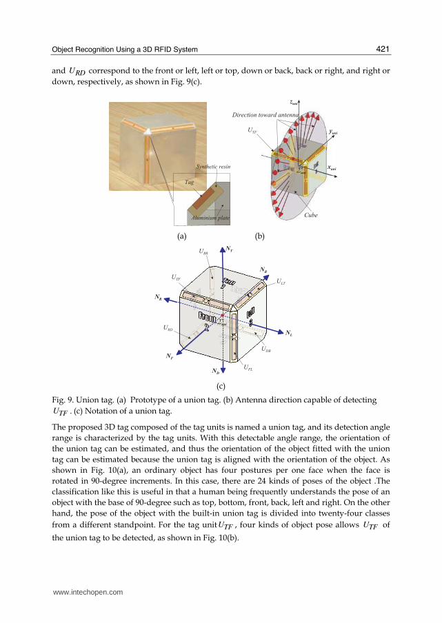
and RDU correspond to the front or left, left or top, down or back, back or right, and right or
down, respectively, as shown in Fig. 9(c).
(a) (b)
(c)
Fig. 9. Union tag. (a) Prototype of a union tag. (b) Antenna direction capable of detecting
TFU . (c) Notation of a union tag.
The proposed 3D tag composed of the tag units is named a union tag, and its detection angle
range is characterized by the tag units. With this detectable angle range, the orientation of
the union tag can be estimated, and thus the orientation of the object fitted with the union
tag can be estimated because the union tag is aligned with the orientation of the object. As
shown in Fig. 10(a), an ordinary object has four postures per one face when the face is
rotated in 90-degree increments. In this case, there are 24 kinds of poses of the object .The
classification like this is useful in that a human being frequently understands the pose of an
object with the base of 90-degree such as top, bottom, front, back, left and right. On the other
hand, the pose of the object with the built-in union tag is divided into twenty-four classes
from a different standpoint. For the tag unit TFU , four kinds of object pose allows TFU of
the union tag to be detected, as shown in Fig. 10(b).
� � �
" � � � � � � � � �
* � ' � � � ' � � � � � �
� + �
� + �
� + � � + �
, ' �
- � �
� � � � � � � � � � . � � � � � � �
- � �
- � /
- / �
, -
, .
, /
, 0
, *
, �
� + �
- 0 �
- � 0
- � �
www.intechopen.com
Development and Implementation of RFID Technology 422
(a) (b) (c) (d)
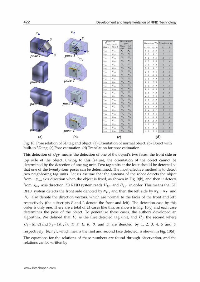
Fig. 10. Pose relation of 3D tag and object. (a) Orientation of normal object. (b) Object with built-in 3D tag. (c) Pose estimation. (d) Translation for pose estimation.
This detection of TFU means the detection of one of the object’s two faces: the front side or
top side of the object. Owing to this feature, the orientation of the object cannot be determined by the detection of one tag unit. Two tag units at the least should be detected so that one of the twenty-four poses can be determined. The most effective method is to detect two neighboring tag units. Let us assume that the antenna of the robot detects the object
from uniy− axis direction when the object is fixed, as shown in Fig. 9(b), and then it detects
from unix axis direction. 3D RFID system reads TFU and LTU in order. This means that 3D
RFID system detects the front side denoted by FN , and then the left side by LN . FN and
LN also denote the direction vectors, which are normal to the faces of the front and left,
respectively (the subscripts F and L denote the front and left). The detection case by this order is only one. There are a total of 24 cases like this, as shown in Fig. 10(c) and each case determines the pose of the object. To generalize these cases, the authors developed an
algorithm. We defined that iU is the first detected tag unit, and jU the second where
( 1, 2)iU i i= and ( 1, 2)jU j j= . T, F, L, R, B, and D are denoted by 1, 2, 3, 4, 5 and 6,
respectively. [ , ]i jn n , which means the first and second face detected, is shown in Fig. 10(d).
The equations for the relations of these numbers are found through observation, and the relations can be written by
� � �
� � � � � � � � � � � $ � � �
- � � � - � / � � � � � � � � , . , /
- � � � - / � � , - , /
- � � � - � � � , - , �
- � � � - 0 � � , . , �
- � / � - � � � , / , .
- � / � - / � � , - , .
- � / � - � � � , - , *
- � / � - � 0 � , / , *
- / � � � � � � � � � � - � � � , / , -
- / � � - � / � , . , -
- / � � - 0 � � , . , 0
- / � � - � 0 � , / , 0
- � � � - � � � , � , -
- � � � - � / � , * , -
- � � � - 0 � � , * , 0
- � � � - � 0 � , � , 0
- 0 � � - � � � , � , .
- 0 � � - / � � , 0 , .
- 0 � � - � � � , 0 , *
- 0 � � - � 0 � , � , *
- � 0 � - � / � , * , /
- � 0 � - / � � , 0 , /
- � 0 � - � � � , 0 , �
- � 0 � - 0 � � , * , �
� � � � � � �- 1 � � � � * � � � � � 0 2
� � � � � �� � � � � � � � � �
� � � � � � � � / � �� � � � � � � � � � � � �
� � � � $ � � � � � � $ � � � % � � � � � � � � � � � � %
� � � � $ � � � � � � % � � � � � � $ � � � � � � � � � %
� � � � $ � � � � � � ) � � � & � � $ � � � � � � � � � )
� � � � $ � � � � � � � � � ) � � � � � � � � � � � � )
$ � � � % � � � � � � � � � � $ � � % � � � � � � � � � �
$ � � � % � � � � � � % � � � � � � $ � � � � � � � � � �
$ � � � % � � � � � � ) � � � & � � $ � � � � � � � � &
$ � � � % � � � � � � & � � � � � % � � � � � � � � &
% � � � � � � � � � � � � � � $ � � % � � � � � � � � $
% � � � � � � � � � � $ � � � % � � � � � � � � � � � $
% � � � � � � � � � � � � � ) � � � � � � � � � � �
% � � � � � � � � � � & � � � � � % � � � � � � � �
) � � � & � � � � � � � � � � $ � � ) � � � � � � � � $
) � � � & � � � � � � $ � � � % � � & � � � � � � � � $
) � � � & � � � � � � � � � ) � � & � � � � � � � �
) � � � & � � � � � � & � � � � � ) � � � � � � � �
� � � ) � � � � � � � � � � $ � � ) � � � � � � � � �
� � � ) � � � � � � % � � � � � � � � � � � � � � �
� � � ) � � � � � � ) � � � & � � � � � � � � � � &
� � � ) � � � � � � & � � � � � ) � � � � � � � � &
& � � � � � � � � � $ � � � % � � & � � � � � � � � %
& � � � � � � � � � % � � � � � � � � � � � � � � %
& � � � � � � � � � ) � � � & � � � � � � � � � � )
& � � � � � � � � � � � � ) � � & � � � � � � � � )
� � � � � � � � � + � 3
' � � � � ' � $ � � � � � ' 4 � � � ' 4 $
� � � � � � � � � + � 3
� � � � � � � � � � 4
www.intechopen.com
Object Recognition Using a 3D RFID System 423
[ , ]
[min( )min( )] 7 9
[max( )max( )] 7
[max( )min( )] 7
[min( )max( )] 7
i j
i j MM MM
i j mm
i j mM
i j Mm
n n
U U if S or S
U U if S
U U if S
U U if S
≤ ≥⎧⎪ =⎪= ⎨ =⎪⎪ =⎩
. (5)
where MMS , mmS , mMS ,and MmS are as shown below.
max( ) max( )
min( ) min( )
min( ) max( )
max( ) min( )
MM i j
mm i j
mM i j
Mm i j
S U U
S U U
S U U
S U U
= += += += +
. (6)
Using Eqs. (5) and (6), the orientation of the object with the built-in 3D tag can be determined.
5. Position and orientation estimation of object
5.1 Position estimation
(a)
(b)
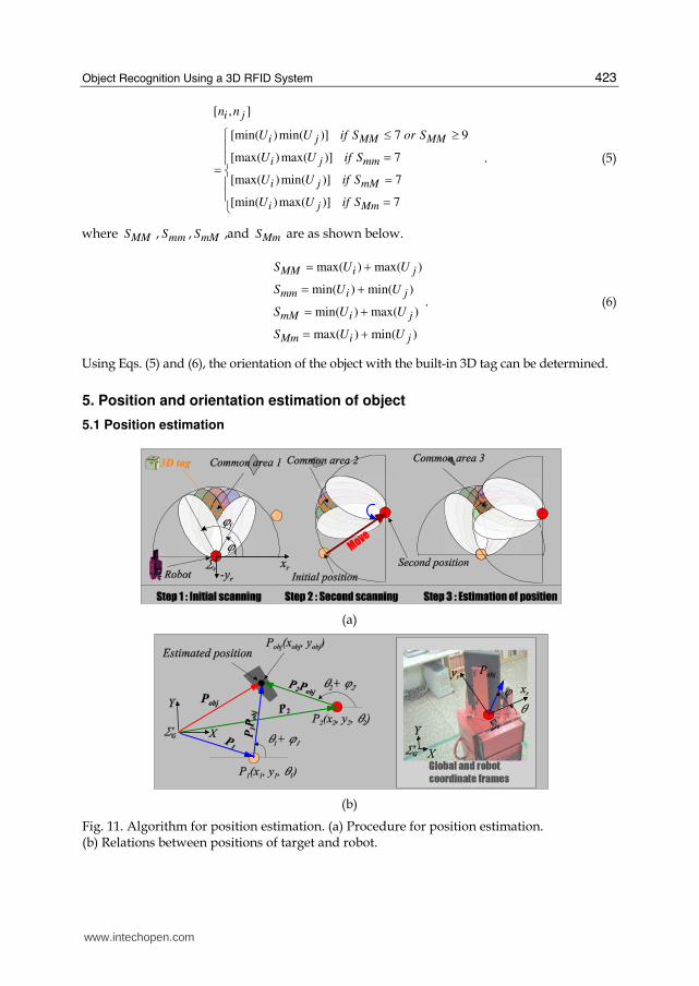
Fig. 11. Algorithm for position estimation. (a) Procedure for position estimation. (b) Relations between positions of target and robot.
www.intechopen.com

Development and Implementation of RFID Technology 424
To complete a mission for manipulating a target, the robot has to know the position of the target. Fig. 11 shows how the 3D RFID system is used. The proposed system can rotate the RFID antenna to scan for finding objects, and it can estimate the position of the 3D tag. As shown in Fig. 11(a), the robot rotates the antenna from the right-hand to the left-hand. The 3D tag is initially detected when the direction angle of the antenna is iϕ , and the tag is
detected until the angle is fϕ . Thus, it can be said that the tag will be placed in the common
area 1 through this scanning procedure. In the next step, the robot moves to the second position, and then repeats the procedure. From steps 1 and 2, the position of the 3D tag is one point in the common area 3. Object detection by scanning has been used by the other robots, which have the sensors with a detection range. However, the results obtained from scanning of these sensors differ from the results of the 3D RFID system. For example, the main purpose of the procedure using ultrasonic sensors is to give the robot not the position but geometry data of the environments such as walls and obstacles (the position is already determined because the distance and direction of the object have been measured when detected), or the procedure is performed to compensate the error data when the sensor does not detect the object because the object is a sharp edgy shape, etc. The ultrasonic sensor or laser range finder is very useful for sensing unspecified objects such as mapping environments or avoiding obstacles, but these sensors cannot find and sense the specified target because the sensor cannot identify target. On the other hand, the robot with the 3D RFID system can identify the target even if the scanning procedure by the 3D RFID system cannot exactly determine the position of the target because the RFID antenna itself does not have capability to read distance between the antenna and the tag. Thus, this scanning should be used not for determining, but for estimating the position of the target. The steps in Fig. 11(a) are the pre-process for the position determination by other sensors capable of distance measuring. The other sensors of the robot with the 3D RFID system can easily detect the object and determine rapidly the position because the robot already knows roughly the position of the object, whether the object exists or not, what the object is, and how it is posed. Fig. 11(b) shows the position estimation of the proposed system. In this
figure, GΣ and rΣ are global and robot coordinates. objP is the position vector of the object
in global coordinates. 1P and 2P are the position vectors of the robot at 1P and 2P ,
respectively. objP can be written by
1 1obj obj= +P P P P . (7)
When the robot’s pose and the direction of the RFID antenna are considered, Eq. (7) can be rewritten by
1 1 1 1
1 1 1 1
| | cos( )
| | sin( )
objobj
obj
x
y
θ ϕθ ϕ
+ ⋅ +⎡ ⎤= ⎢ ⎥+ ⋅ +⎢ ⎥⎣ ⎦P P
PP P
, (8)
where 1θ and 2θ are the angular differences between the global and robot frames at 1P and
2P . 1ϕ , which means the antenna direction angle, is the angle of 1 objP P from the rx -axis,
and 2ϕ is the angle of 2 objP P from the rx -axis. 1| |objP P is rewritten by
2 21 1 2
2 2 1 1
sin( )| | | |
sin( )obj
θ ϕ ψθ ϕ θ ϕ
+ −= ⋅ + − −P P P P , (9)
www.intechopen.com
Object Recognition Using a 3D RFID System 425
where 1 2 1
2 1
tany y
x xψ − −= − and 1ϕ and 2ϕ are obtained from ( ) / 2i fϕ ϕ+ at 1P and 2P ,
respectively. Thus, we finally obtain
2 21 1 2 1 1
2 2 1 1
2 21 1 2 1 1
2 2 1 1
sin( )| | cos( )
sin( )
sin( )| | sin( )
sin( )
obj
x
y
θ ϕ ψ θ ϕθ ϕ θ ϕθ ϕ ψ θ ϕθ ϕ θ ϕ
+ −⎡ ⎤+ ⋅ ⋅ +⎢ ⎥+ − −⎢ ⎥= ⎢ ⎥+ −+ ⋅ ⋅ +⎢ ⎥+ − −⎣ ⎦
P P
P
P P
. (10)
Eq. (10) is obtained from the relations of the steps 1 and 2. Theoretically, the position can be estimated with only step 1 because the common area 1 is determined with the two ellipsoids computed. The steps 1 and 2, however, are required to execute the orientation estimation, which will be presented in the next section. Since the orientation estimation is always accompanied with the position estimation and the position estimation by the two steps is more accurate, the position estimation using these steps is reasonable.
5.2 Orientation estimation
(a) (b) (c)
(d) (e)
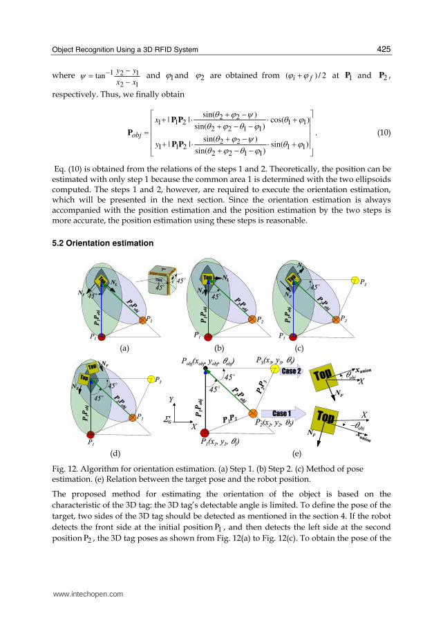
Fig. 12. Algorithm for orientation estimation. (a) Step 1. (b) Step 2. (c) Method of pose estimation. (e) Relation between the target pose and the robot position.
The proposed method for estimating the orientation of the object is based on the
characteristic of the 3D tag: the 3D tag’s detectable angle is limited. To define the pose of the
target, two sides of the 3D tag should be detected as mentioned in the section 4. If the robot
detects the front side at the initial position 1P , and then detects the left side at the second
position 2P , the 3D tag poses as shown from Fig. 12(a) to Fig. 12(c). To obtain the pose of the
www.intechopen.com

Development and Implementation of RFID Technology 426
target, the robot must determine the second position. If the second position is not chosen
properly, the left side cannot be detected because the antenna has a limited direction and
sensing range for detecting the 3D tag. The determination of the second position depends on
the detectable angle range of the tag unit of the 3D tag; the maximum is 45c and the
minimum 45− c from Eq. (4). When the tag poses as shown in Fig. 12(a), the angle between
the vectors FN denoting the front side and 1 obj−P P should be less than 45c to detect the
front side of the 3D tag. In case of Fig. 12(b), LN and 2 obj−P P should be more than 45c to
detect the left side. Thus, it is reasonable that the angle between 1 objPP and 2 objP P is 45c . In
addition, when the robot is placed at the second position 2P , the target should be within the
sensing range of the antenna. Hence, the distance between the target position Pobj and 2P
should be chosen properly. This distance is substituted with that between the common area
1 and 1P . In the previous section, the common area 1 is used to obtain 1ϕ , but the position
of the area is not considered. In other words, this common area is used as a guide for the
choice of 2P to estimate the orientation even if the area is not used for the position
estimation. Though the robot moves to 2P , the left side of the 3D tag cannot be detected as
shown in Fig. 12(c). In such a case, the robot moves to 3P and detects the left side. As shown
in Fig. 12(e), the positions of 1P , 2P , 3P , and objP are solved as follows.
2P can be written by
2 1 1 2= +P P PP , (11)
where 1 2PP is written by
11 2
1
1
1
2 2 | | cos22.5
2 2 | | sin22.5
| |
2
| |1
2
obj
obj
obj
obj
⎡ ⎤− ⋅⎢ ⎥= ⎢ ⎥− ⋅⎢ ⎥⎣ ⎦⎡ ⎤⎢ ⎥⎢ ⎥= ⎢ ⎥⎢ ⎥−⎢ ⎥⎣ ⎦
c
c
P PP P
P P
P P
P P
. (12)
Thus, 2P becomes Eq. (13).
11
21
1
| |
2
| |1
2
obj
obj
x
y
⎡ ⎤+⎢ ⎥⎢ ⎥= ⎢ ⎥⎢ ⎥+ −⎢ ⎥⎣ ⎦
P P
PP P
. (13)
3P can be written by Eq. (14)
3 1 1 3= +P P P P , (14)
where 1 3PP is given by
www.intechopen.com
Object Recognition Using a 3D RFID System 427
1
1 31
| |
| |
obj
obj
⎡ ⎤= ⎢ ⎥⎢ ⎥⎣ ⎦P P
P PP P
. (15)
Thus, 3P becomes Eq. (16).
1 3
31 3
| |
| |
obj
obj
x
y
+⎡ ⎤= ⎢ ⎥+⎢ ⎥⎣ ⎦P P
PP P
. (16)
Consequently, we finally obtain
1 11 1 2 1 1
1 11 1 2 1 1
sin( 22.5 )| | cos( )
sin( 22.5 )| | sin( )
2
2obj
obj
x
y
θ ϕ θ ϕ
θ ϕ θ ϕθ
++ ⋅ ⋅ +
++ ⋅ ⋅ +
⎡ ⎤+⎢ ⎥⎢ ⎥⎢ ⎥+⎢ ⎥= ⎢ ⎥⎢ ⎥⎢ ⎥⎢ ⎥⎢ ⎥⎣ ⎦
c
c
P P
P P P , (17)
where 1 2 2 1| | sec22.5 | |x x= −P P c . The orientation objθ of the target can be obtained by the
following method. If the robot detects the front side of the 3D tag at the position 1P and
detects the left side of the 3D tag at 2P , as shown in the case 1 of Fig. 12(e), the orientation
objθ of the target can be written by
45 0objθ− ≤ ≤c c . (18)
If the robot detects the front side of the 3D tag at the position P1, does not detect the left side
of the 3D tag at 2P , and then detects the left side of the 3D tag at 3P , as shown in the case 2
of Fig. 12(e), the orientation objθ of the target can be written by
0 45objθ≤ ≤c c . (19)
This result is satisfied wherever the target is placed in the common area 1 and how it is posed, as shown in Fig. 12(d).
6. Experiments
Figure 13 shows the procedure of the experiment based on the proposed algorithm. In the
test space, the target is placed at the random position targetP (1040, 900, 0). The target is the
box with the built-in 3D tag. The robot is initially located on Pr (500, 500, 0) in the global
map. Using only the 3D RFID system, the robot DRP I searches and detects the target, and
then, the robot estimates the position and orientation of the target. This experiment is
repeated several times. Figure 14 shows the results of the position estimation. The results of
the orientation estimation are always regular ( 0 45objθ≤ ≤c c ). Currently, the orientation of
the object by using the 3D RFID system is estimated when the face is rotated in 45c
www.intechopen.com

Development and Implementation of RFID Technology 428
increments. This is because the detection rate cannot be matched to the change of
continuous orientation of the object, as show in Figs. 8(b) and 8(c). If the RFID tag and
antenna suitable for the stable detection rate should be developed, the object’s orientation
estimation using the 3D tag can be extended to various automation systems.
Fig. 13. Experiment of DRP 1.
Fig. 14. Location estimation by only the RFID system.
5 � 4 � � � . � � � � � ' � � � � � � % � � � � �
% � � � � � � � % � � � � � � � � � & � �
% � � � � � � � ' � & � � � � � � � � � � � �
% � � � � � � � � � � � � � � � � � � � � �
% � � � � � � � � ( � � � � � � � � � � � � � ) � � � � � � � � � �
% � � � � " � � % � � � � � � � � � � � �
% � � � � * � � + � � � � � � � � � � � � � � � � � � � � � � � � � �
67�
�8
9 7 � � 8
� $ � �
� � � �
� � : � �
� � & � �
� � ) � �
� � $ � �
� � �� � $ � � � � � ) � � � � � � � & � � � � � � � � � : � � � � � � � � � � � � � � $ � � � � � � ) � � �
; � � � � � � � � � � � � � � � � � � � � �
� � � � � � � � � � � � � � � � �
www.intechopen.com
Object Recognition Using a 3D RFID System 429
7. Conclusions
Up to now, object recognition in robotics has been typically done by vision, ultrasonic
sensors, laser ranger finders etc. Recently, RFID has emerged as a promising technology
that can strengthen object recognition. In this chapter, the 3D RFID system and the 3D tag
were presented. The proposed RFID system can determine if an object as well as other
tags exists, and also can estimate the orientation and position of the object. This feature
considerably reduces the dependence of the robot on other sensors such as vision systems
required for object recognition. With the fast growth of RFID technology, the field of
robotics will benefit greatly, and our research will support the investigation of its use in
practical applications.
8. Acknowledgment
This work was supported by the Ministry of Knowledge Economy (MKE) and Korea Industrial Technology Foundation (KOTEF) through the Human Resource Training Project for Strategic Technology.
9. References
Weiss, I. & Ray, M. (2001). Model-Based Recognition of 3D Objects from Single Images, IEEE Trans. Pattern Analysis, Machine Intelligence, vol. 23, pp. 116-128.
Yamano, K.; Tanaka, K.; Hirayama, M.; Kondo, E.; Kimuro, Y. & Matsumoto, M. (2004). Self-localization of Mobile Robots with RFID System by using Support Vector Machine, in Proc. IEEE/RSJ Int. Conf. Intelligent Robots, Systems, pp. 3756-3761.
Kulyukin, V.; Gharpure, C.; Nicholson, J. & Pavithran, S. (2004 ). RFID in Robot-Assisted Indoor Navigation for the Visually Impaired, in Proc. IEEE/RSJ Int. Conf. Intelligent Robots, Systems, pp. 1979-1984.
Ni, L. M.; Liu, Y.; Lau, Y. C. & Patil, A. P. (2003). LANDMARC: Indoor Location Sensing Using Active RFID, in Proc. IEEE Int. Conf. Pervasive Computing and Communications, pp. 407-415.
Kubitz, O.; Berger, M. O.; Perlick, M. & Dumoulin, R. (1997). Application of radio frequency identification devices to support navigation of autonomous mobile robots, in Proc. IEEE Int. Conf. Vehicular Technology, vol. 1, pp. 126-130.
Tsukiyama, T. (2002). Global Navigation System with RFID Tags, in Proc. SPIE, vol. 4573, pp. 256-264.
Hahnel, D.; Burgard, W.; Fox, D.; Fishkin, K. & Philipose, M. (2004). Mapping and Localization with RFID Technology, in Proc.IEEE Int. Conf. Robotics, Automation, vol. 1, pp. 1015-1020.
Ruff, T. M. & Hession-Kunz, D. (2001). Application of radio-frequency identification systems to collision avoidance in metal/nonmetal mines, IEEE Trans. Industry Applications, vol. 37, pp. 112-116.
Boukraa, M. & Ando, S. (2002). Tag-based vision: assisting 3D scene analysis with radio-frequency tags, in Proc. IEEE Int.Conf. Information Fusion, pp. 412-418.
Mae, Y.; Umetani, T.; Arai, T. & Inoue, E. (2000). Object recognition using appearance models accumulated into environment, in Proc. IEEE Int. Conf. Pattern Recognition, vol. 4, pp. 845-848.
www.intechopen.com

Development and Implementation of RFID Technology 430
Chong, N. Y.; Hongu, H.; Miyazaki, M.; Takemura, K.; Ohara, K.; Ohba, K.; Hirai, S. & Tanie, K. (2004). Robots on Self-Organizing Knowledge Networks, in Proc. IEEE Int. Conf. Robotics, Automation, pp. 3494-3499.
Roh, S. G.; Park, K. H.; Yang, K. W.; Park, J. H.; Kim, H. S.; Lee, H. G. & Choi, H. R. (2004). Development of Dynamically Reconfigurable Personal Robot, in Proc. IEEE Int. Conf. Robotics, Automation, pp. 4023-4028.
Roh, S. G.; Lee, Y. H. & Choi, H. R. (2006). in Proc. IEEE/RSJ Int. Conf. Intelligent Robots and Systems, pp. 5725-5730.
Roh, S. G. & Choi, H. R. (2009). 3D Tag-based RFID System for Recognition of Object, IEEE Trans. Automation Science and Engineering, (in press).
www.intechopen.com
Development and Implementation of RFID TechnologyEdited by Cristina Turcu
ISBN 978-3-902613-54-7Hard cover, 450 pagesPublisher I-Tech Education and PublishingPublished online 01, January, 2009Published in print edition January, 2009
InTech EuropeUniversity Campus STeP Ri Slavka Krautzeka 83/A 51000 Rijeka, Croatia Phone: +385 (51) 770 447 Fax: +385 (51) 686 166www.intechopen.com
InTech ChinaUnit 405, Office Block, Hotel Equatorial Shanghai No.65, Yan An Road (West), Shanghai, 200040, China
Phone: +86-21-62489820 Fax: +86-21-62489821
The book generously covers a wide range of aspects and issues related to RFID systems, namely the designof RFID antennas, RFID readers and the variety of tags (e.g. UHF tags for sensing applications, surfaceacoustic wave RFID tags, smart RFID tags), complex RFID systems, security and privacy issues in RFIDapplications, as well as the selection of encryption algorithms. The book offers new insights, solutions andideas for the design of efficient RFID architectures and applications. While not pretending to becomprehensive, its wide coverage may be appropriate not only for RFID novices but also for experiencedtechnical professionals and RFID aficionados.
How to referenceIn order to correctly reference this scholarly work, feel free to copy and paste the following:
Se-gon Roh and Hyouk Ryeol Choi (2009). Object Recognition Using a 3D RFID System, Development andImplementation of RFID Technology, Cristina Turcu (Ed.), ISBN: 978-3-902613-54-7, InTech, Available from:http://www.intechopen.com/books/development_and_implementation_of_rfid_technology/object_recognition_using_a_3d_rfid_system

© 2009 The Author(s). Licensee IntechOpen. This chapter is distributedunder the terms of the Creative Commons Attribution-NonCommercial-ShareAlike-3.0 License, which permits use, distribution and reproduction fornon-commercial purposes, provided the original is properly cited andderivative works building on this content are distributed under the samelicense.