objectives:• understand latches, timers, counters and … · • understand latches, timers,...
TRANSCRIPT

plc timers - 9.1
9. LATCHES, TIMERS, COUNTERS AND MORE
9.1 INTRODUCTION
More complex systems cannot be controlled with combinatorial logic alone. The main reason for this is that we cannot, or choose not to add sensors to detect all conditions. In these cases we can use events to estimate the condition of the system. Typical events used by a PLC include;
first scan of the PLC - indicating the PLC has just been turned ontime since an input turned on/off - a delaycount of events - to wait until set number of events have occurredlatch on or unlatch - to lock something on or turn it off
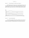
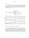
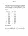
The common theme for all of these events is that they are based upon one of two questions "How many?" or "How long?". An example of an event based device is shown in Figure 9.1. The input to the device is a push button. When the push button is pushed the input to the device turns on. If the push button is then released and the device turns off, it is a logical device. If when the push button is release the device stays on, is will be one type of event based device. To reiterate, the device is event based if it can respond to one or more things that have happened before. If the device responds only one way to the immediate set of inputs, it is logical.
Topics:
Objectives:• Understand latches, timers, counters and MCRs.• To be able to select simple internal memory bits.
• Latches, timers, counters and MCRs• Design examples• Internal memory locations are available, and act like outputs

plc timers - 9.2
Figure 9.1 An Event Driven Device
9.2 LATCHES
A latch is like a sticky switch - when pushed it will turn on, but stick in place, it must be pulled to release it and turn it off. A latch in ladder logic uses one instruction to latch, and a second instruction to unlatch, as shown in Figure 9.2. The output with an L inside will turn the output D on when the input A becomes true. D will stay on even if A turns off. Output D will turn off if input B becomes true and the output with a U inside becomes true (Note: this will seem a little backwards at first). If an output has been latched on, it will keep its value, even if the power has been turned off.
Figure 9.2 A Ladder Logic Latch
e.g. A Start Push Button
+V
Push Button
Device
Push Button
Device
Device
(Logical Response)
(Event Response)
On/Off
time
A
D
A C
B
D
L
U

plc timers - 9.3
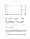
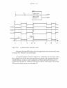
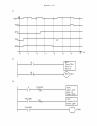
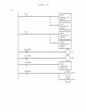
The operation of the ladder logic in Figure 9.2 is illustrated with a timing diagram in Figure 9.3. A timing diagram shows values of inputs and outputs over time. For exam-ple the value of input A starts low (false) and becomes high (true) for a short while, and then goes low again. Here when input A turns on both the outputs turn on. There is a slight delay between the change in inputs and the resulting changes in outputs, due to the pro-gram scan time. Here the dashed lines represent the output scan, sanity check and input scan (assuming they are very short.) The space between the dashed lines is the ladder logic scan. Consider that when A turns on initially it is not detected until the first dashed line. There is then a delay to the next dashed line while the ladder is scanned, and then the out-put at the next dashed line. When A eventually turns off, the normal output C turns off, but the latched output D stays on. Input B will unlatch the output D. Input B turns on twice, but the first time it is on is not long enough to be detected by an input scan, so it is ignored. The second time it is on it unlatches output D and output D turns off.
A
B
C
D
event too short to be noticed (aliasing)
These lines indicate PLC input/output refresh times. At this timeall of the outputs are updated, and all of the inputs are read.
The space between the lines is the scan time for the ladder logic.The spaces may vary if different parts of the ladder diagram areexecuted each time through the ladder (as with state space code).
Notice that some inputs can be ignored if at the wrong time,and there can be a delay between a change in input, and a changein output.
Timing Diagram
The space is a function of the speed of the PLC, and the number ofLadder logic elements in the program.
plc timers - 9.4
Figure 9.3 A Timing Diagram for the Ladder Logic in Figure 9.2
The timing diagram shown in Figure 9.3 has more details than are normal in a tim-ing diagram as shown in Figure 9.4. The brief pulse would not normally be wanted, and would be designed out of a system either by extending the length of the pulse, or decreas-ing the scan time. An ideal system would run so fast that aliasing would not be possible.
Figure 9.4 A Typical Timing Diagram
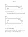
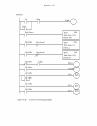
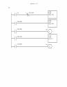
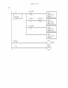
A more elaborate example of latches is shown in Figure 9.5. In this example the addresses are for an Allen-Bradley Micrologix controller. The inputs begin with I/, fol-lowed by an input number. The outputs begin with O/, followed by an output number.
A
B
C
D
plc timers - 9.5
Figure 9.5 A Latch Example
A normal output should only appear once in ladder logic, but latch and unlatch instructions may appear multiple times. In Figure 9.5 a normal output O/2 is repeated twice. When the program runs it will examine the fourth line and change the value of O/2 in memory (remember the output scan does not occur until the ladder scan is done.) The last line is then interpreted and it overwrites the value of O/2. Basically, only the last line will change O/2.
Latches are not used universally by all PLC vendors, others such as Siemens use
I/0
I/1
I/0
I/0
I/1
O/0
O/1
O/1
O/2
O/2
L
U
I/0
I/1
O/0
O/1
O/2
plc timers - 9.6
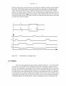
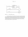
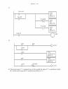
flip-flops. These have a similar behavior to latches, but a different notation as illustrated in Figure 9.6. Here the flip-flop is an output block that is connected to two different logic rungs. The first rung shown has an input A connected to the S setting terminal. When A goes true the output value Q will go true. The second rung has an input B connected to the R resetting terminal. When B goes true the output value Q will be turned off. The output Q will always be the inverse of Q. Notice that the S and R values are equivalent to the L and U values from earlier examples.
Figure 9.6 Flip-Flops for Latching Values
9.3 TIMERS
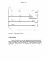
There are four fundamental types of timers shown in Figure 9.7. An on-delay timer will wait for a set time after a line of ladder logic has been true before turning on, but it will turn off immediately. An off-delay timer will turn on immediately when a line of lad-der logic is true, but it will delay before turning off. Consider the example of an old car. If you turn the key in the ignition and the car does not start immediately, that is an on-delay. If you turn the key to stop the engine but the engine doesn’t stop for a few seconds, that is an off delay. An on-delay timer can be used to allow an oven to reach temperature before starting production. An off delay timer can keep cooling fans on for a set time after the
S
R
Q
Q
A
B
Q
Q
A
B

plc timers - 9.7
oven has been turned off.
Figure 9.7 The Four Basic Timer Types
A retentive timer will sum all of the on or off time for a timer, even if the timer never finished. A nonretentive timer will start timing the delay from zero each time. Typi-cal applications for retentive timers include tracking the time before maintenance is needed. A non retentive timer can be used for a start button to give a short delay before a conveyor begins moving.
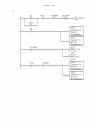
An example of an Allen-Bradley TON timer is shown in Figure 9.8. The rung has a single input A and a function block for the TON. (Note: This timer block will look differ-ent for different PLCs, but it will contain the same information.) The information inside the timer block describes the timing parameters. The first item is the timer number T4:0. This is a location in the PLC memory that will store the timer information. The T4: indi-cates that it is timer memory, and the 0 indicates that it is in the first location. The time base is 1.0 indicating that the timer will work in 1.0 second intervals. Other time bases are available in fractions and multiples of seconds. The preset is the delay for the timer, in this case it is 4. To find the delay time multiply the time base by the preset value 4*1.0s = 4.0s. The accumulator value gives the current value of the timer as 0. While the timer is running the Accumulated value will increase until it reaches the preset value. Whenever the input A is true the EN output will be true. The DN output will be false until the accumulator has reached the preset value. The EN and DN outputs cannot be changed when programming, but these are important when debugging a ladder logic program. The second line of ladder logic uses the timer DN output to control another output B.
retentive
nonretentive
on-delay off-delay
RTO
TON
RTF
TOF
TON - Timer ONTOF - Timer OFfRTO - Retentive Timer OnRTF - Retentive Timer oFf
plc timers - 9.8
Figure 9.8 An Allen-Bradley TON Timer
The timing diagram in Figure 9.8 illustrates the operation of the TON timer with a 4 second on-delay. A is the input to the timer, and whenever the timer input is true the EN enabled bit for the timer will also be true. If the accumulator value is equal to the preset value the DN bit will be set. Otherwise, the TT bit will be set and the accumulator value will begin increasing. The first time A is true, it is only true for 3 seconds before turning off, after this the value resets to zero. (Note: in a retentive time the value would remain at 3 seconds.) The second time A is true, it is on more than 4 seconds. After 4 seconds the TT bit turns off, and the DN bit turns on. But, when A is released the accumulator resets to zero, and the DN bit is turned off.
A value can be entered for the accumulator while programming. When the pro-gram is downloaded this value will be in the timer for the first scan. If the TON timer is not enabled the value will be set back to zero. Normally zero will be entered for the preset
ATON
Timer T4:0Time Base 1.0Preset 4Accumulator 0
A
T4:0/DN
(DN)
(EN)
T4:0 Accum.0
34
0 3 6 9 14 17 19
T4:0/EN
2
13
T4:0/TT
T4:0/DNB
B
plc timers - 9.9
value.
The timer in Figure 9.9 is identical to that in Figure 9.8, except that it is retentive. The most significant difference is that when the input A is turned off the accumulator value does not reset to zero. As a result the timer turns on much sooner, and the timer does not turn off after it turns on. A reset instruction will be shown later that will allow the accumulator to be reset to zero.
Figure 9.9 An Allen Bradley Retentive On-Delay Timer
An off delay timer is shown in Figure 9.10. This timer has a time base of 0.01s, with a preset value of 350, giving a total delay of 3.5s. As before the EN enable for the timer matches the input. When the input A is true the DN bit is on. Is is also on when the input A has turned off and the accumulator is counting. The DN bit only turns off when the input A has been off long enough so that the accumulator value reaches the preset. This type of timer is not retentive, so when the input A becomes true, the accumulator resets.
ARTO
Timer T4:0Time Base 1.0Preset 4Accum. 0
A
T4:0/DN
(DN)
(EN)
T4:0.Accum. 0
34
0 3 6 9 14 17 19
T4:0/EN
10
T4:0/TT
plc timers - 9.10
Figure 9.10 An Allen Bradley Off-Delay Timer
Retentive off-delay (RTF) timers have few applications and are rarely used, there-fore many PLC vendors do not include them.
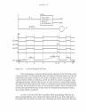
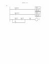
An example program is shown in Figure 9.11. In total there are four timers used in this example, T4:1 to T4:4. The timer instructions are shown with a shorthand notation with the timebase and preset values combined as the delay. All four different types of counters have the input I/1. Output O/1 will turn on when the TON counter T4:1 is done. All four of the timers can be reset with input I/2.
ATOF
Timer T4:0Time Base 0.01Preset 350Accum. 0
T4:0/DN
(DN)
(EN)
T4:0.Accum.0
33.5
0 3 6 10 16 18 20
T4:0 EN
9.5
T4:0/TT
A

plc timers - 9.11
Figure 9.11 A Timer Example
A timing diagram for this example is shown in Figure 9.12. As input I/1 is turned on the TON and RTO timers begin to count and reach 4s and turn on. When I/2 becomes true it resets both timers and they start to count for another second before I/1 is turned off. After the input is turned off the TOF and RTF both start to count, but neither reaches the 4s preset. The input I/1 is turned on again and the TON and RTO both start counting. The RTO turns on one second sooner because it had 1s stored from the 7-8s time period. After I/1 turns off again both the off delay timers count down, and reach the 4 second delay, and turn on. These patterns continue across the diagram.
I/1
I/1
I/1
I/1
O/1T4:1/DN
I/2
I/2
I/2
I/2
RTO T4:2delay 4 sec
TON T4:1delay 4 sec
RTF T4:4delay 4 sec
TOF T4:3delay 4 sec
RES T4:1
RES T4:2
RES T4:3
RES T4:4

plc timers - 9.12
Figure 9.12 A Timing Diagram for Figure 9.11
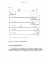
Consider the short ladder logic program in Figure 9.13 for control of a heating oven. The system is started with a Start button that seals in the Auto mode. This can be stopped if the Stop button is pushed. (Remember: Stop buttons are normally closed.) When the Auto goes on initially the TON timer is used to sound the horn for the first 10 seconds to warn that the oven will start, and after that the horn stops and the heating coils start. When the oven is turned off the fan continues to blow for 300s or 5 minutes after.
0 5 10 15 20 25 30 35 40time(sec)
I/1
T4:1/DN
T4:2/DN
T4:3/DN
T4:4/DN
O/1
I/2

plc timers - 9.13
Figure 9.13 A Timer Example
A program is shown in Figure 9.14 that will flash a light once every second. When the PLC starts, the second timer will be off and the T4:1/DN bit will be off, therefore the normally closed input to the first timer will be on. T4:0 will start timing until it reaches 0.5s, when it is done the second timer will start timing, until it reaches 0.5s. At that point T4:1/DN will become true, and the input to the first time will become false. T4:0 is then set back to zero, and then T4:1 is set back to zero. And, the process starts again from the beginning. In this example the first timer is used to drive the second timer. This type of arrangement is normally called cascading, and can use more that two timers.
TONTimer T4:0Delay 10s
Note: For the remainder of the text I will use the shortened notation for timers shown above. This will save space and reduce confusion.
TOFTimer T4:1Delay 300s
Horn
Heating Coils
Auto
T4:0/TT
T4:0/DN
Auto
Auto
StopStart
FanT4:1/DN

plc timers - 9.14
Figure 9.14 Another Timer Example
9.4 COUNTERS
There are two basic counter types: count-up and count-down. When the input to a count-up counter goes true the accumulator value will increase by 1 (no matter how long the input is true.) If the accumulator value reaches the preset value the counter DN bit will be set. A count-down counter will decrease the accumulator value until the preset value is reached.
An Allen Bradley count-up (CTU) instruction is shown in Figure 9.15. The instruction requires memory in the PLC to store values and status, in this case is C5:0. The C5: indicates that it is counter memory, and the 0 indicates that it is the first location. The preset value is 4 and the value in the accumulator is 2. If the input A were to go from false to true the value in the accumulator would increase to 3. If A were to go off, then on again the accumulator value would increase to 4, and the DN bit would go on. The count can continue above the preset value. If input B goes true the value in the counter accumulator will become zero.
TONTimer T4:0Delay 0.5s
Light
T4:1/DN
T4:1/TT
TONTimer T4:1Delay 0.5s
T4:0/DN
plc timers - 9.15
Figure 9.15 An Allen Bradley Counter
Count-down counters are very similar to count-up counters. And, they can actually both be used on the same counter memory location. Consider the example in Figure 9.16, the example input I/1 drives the count-up instruction for counter C5:1. Input I/2 drives the count-down instruction for the same counter location. The preset value for a counter is stored in memory location C5:1 so both the count-up and count-down instruction must have the same preset. Input I/3 will reset the counter.
CTUA Counter C5:0
Preset 4Accum. 2
(CU)
(DN)
C5:0/DN
C5:0RES
X
B

plc timers - 9.16
Figure 9.16 A Counter Example
The timing diagram in Figure 9.16 illustrates the operation of the counter. If we assume that the value in the accumulator starts at 0, then the I/1 inputs cause it to count up to 3 where it turns the counter C5:1 on. It is then reset by input I/3 and the accumulator value goes to zero. Input I/1 then pulses again and causes the accumulator value to increase again, until it reaches a maximum of 5. Input I/2 then causes the accumulator value to decrease down below 3, and the counter turns off again. Input I/1 then causes it to increase, but input I/3 resets the accumulator back to zero again, and the pulses continue until 3 is reached near the end.
I/1
I/2
I/3
O/1C5:1/DN
I/1
I/2
I/3
C5:1/DN
O/1
CTU C5:1preset 3
CTD C5:1preset 3
RES C5:1

plc timers - 9.17
The program in Figure 9.17 is used to remove 5 out of every 10 parts from a con-veyor with a pneumatic cylinder. When the part is detected both counters will increase their values by 1. When the sixth part arrives the first counter will then be done, thereby allowing the pneumatic cylinder to actuate for any part after the fifth. The second counter will continue until the eleventh part is detected and then both of the counters will be reset.
Figure 9.17 A Counter Example
9.5 MASTER CONTROL RELAYS (MCRs)
In an electrical control system a Master Control Relay (MCR) is used to shut down a section of an electrical system, as shown earlier in the electrical wiring chapter. This concept has been implemented in ladder logic also. A section of ladder logic can be put between two lines containing MCR’s. When the first MCR coil is active, all of the inter-mediate ladder logic is executed up to the second line with an MCR coil. When the first MCR coil in inactive, the ladder logic is still examined, but all of the outputs are forced off.
Consider the example in Figure 9.18. If A is true, then the ladder logic after will be
CTUCounter C5:0Preset 6
CTUCounter C5:1Preset 11
part present
C5:0/DN part present pneumaticcylinder
C5:1/DNC5:0
C5:1
RES
RES
plc timers - 9.18
executed as normal. If A is false the following ladder logic will be examined, but all of the outputs will be forced off. The second MCR function appears on a line by itself and marks the end of the MCR block. After the second MCR the program execution returns to nor-mal. While A is true, X will equal B, and Y can be turned on by C, and off by D. But, if A becomes false X will be forced off, and Y will be left in its last state. Using MCR blocks to remove sections of programs will not increase the speed of program execution signifi-cantly because the logic is still examined.
Figure 9.18 MCR Instructions
If the MCR block contained another function, such as a TON timer, turning off the MCR block would force the timer off. As a general rule normal outputs should be outside MCR blocks, unless they must be forced off when the MCR block is off.
AMCR
MCR
Note: If a normal input is used inside an MCR block it will be forced off. If the output is also used in other MCR blocks the last one will be forced off. The MCR is designed to fully stop an entire section of ladder logic, and is best used this way in ladder logic designs.
B
CL
DU
X
Y
Y
plc timers - 9.19
9.6 INTERNAL RELAYS
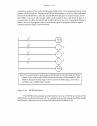
Inputs are used to set outputs in simple programs. More complex programs also use internal memory locations that are not inputs or outputs. These are sometimes referred to as ’internal relays’ or ’control relays’. Knowledgeable programmers will often refer to these as ’bit memory’. In the Allen Bradley PLCs these addresses begin with ’B3’ by default. The first bit in memory is ’B3:0/0’, where the first zero represents the first 16 bit word, and the second zero represents the first bit in the word. The sequence of bits is shown in Figure 9.19. The programmer is free to use these memory locations however they see fit.
Figure 9.19 Bit memory
An example of bit memory usage is shown in Figure 9.20. The first ladder logic rung will turn on the internal memory bit ’B3:0/0’ when input ’hand_A’ is activated, and input ’clear’ is off. (Notice that the B3 memory is being used as both an input and output.) The second line of ladder logic similar. In this case when both inputs have been activated, the output ’press on’ is active.
bitnumber
01234567891011121314151617
memorylocation
B3:0/0B3:0/1B3:0/2B3:0/3B3:0/4B3:0/5B3:0/6B3:0/7B3:0/8B3:0/9B3:0/10B3:0/11B3:0/12B3:0/13B3:0/14B3:0/15B3:1/0B3:1/1
bitnumber
1819202122232425262728293031323334etc...
memorylocation
B3:1/2B3:1/3B3:1/4B3:1/5B3:1/6B3:1/7B3:1/8B3:1/9B3:1/10B3:1/11B3:1/12B3:1/13B3:1/14B3:1/15B3:2/0B3:2/1B3:2/2etc...

plc timers - 9.20
Figure 9.20 An example using bit memory
Bit memory was presented briefly here because it is important for design tech-niques in the following chapters, but it will be presented in greater depth after that.
9.7 DESIGN CASES
The following design cases are presented to help emphasize the principles pre-sented in this chapter. I suggest that you try to develop the ladder logic before looking at the provided solutions.
9.7.1 Basic Counters And Timers
Problem: Develop the ladder logic that will turn on an output light, 15 seconds after switch A has been turned on.
hand_A
hand_B
clear
clear
A_pushed
B_pushed
A_pushed
B_pushed
A_pushed B_pushed
press_on
I:0/0
I:0/1
I:0/2
I:0/2
B3:0/0
B3:0/0
B3:0/1
B3:0/1
B3:0/0 B3:0/1
O:0/0
plc timers - 9.21
Figure 9.21 A Simple Timer Example
Problem: Develop the ladder logic that will turn on a light, after switch A has been closed 10 times. Push button B will reset the counters.
Figure 9.22 A Simple Counter Example
9.7.2 More Timers And Counters
Problem: Develop a program that will latch on an output B 20 seconds after input A has been turned on. After A is pushed, there will be a 10 second delay until A can have any effect again. After A has been pushed 3 times, B will be turned off.
A TONTime base: 1.0Preset 15
T4:0
T4:0/DNLight
Solution:
A CTUPreset 10Accum. 0
C5:0
BC5:0 RES
C5:0/DNLight
Solution:

plc timers - 9.22
Figure 9.23 A More Complex Timer Counter Example
9.7.3 Deadman Switch
Problem: A motor will be controlled by two switches. The Go switch will start the motor and the Stop switch will stop it. If the Stop switch was used to stop the motor, the Go switch must be thrown twice to start the motor. When the motor is active a light should be turned on. The Stop switch will be wired as normally closed.
On CTUPreset 3Accum. 0
C5:0
On TONTime base: 1.0Preset 20
T4:0
OnA
L
LightT4:0/DNL
T4:0/DN TONTime base: 1.0Preset 10
T4:1
OnT4:1/DNU
LightC5:0/DNU
Solution:
plc timers - 9.23
Figure 9.24 A Motor Starter Example
9.7.4 Conveyor
Problem: A conveyor is run by switching on or off a motor. We are positioning parts on the conveyor with an optical detector. When the optical sensor goes on, we want to wait 1.5 seconds, and then stop the conveyor. After a delay of 2 seconds the conveyor will start again. We need to use a start and stop button - a light should be on when the sys-tem is active.
Go CTUPreset 2Accum. 1
C5:0
Motor StopC5:0
MotorLight
RES
Motor
C5:0/DN StopMotor
Consider:- what will happen if stop is pushed and the motor is not running?
Solution:
plc timers - 9.24
Figure 9.25 A Conveyor Controller Example
9.7.5 Accept/Reject Sorting
Problem: For the conveyor in the last case we will add a sorting system. Gages have been attached that indicate good or bad. If the part is good, it continues on. If the part is bad, we do not want to delay for 2 seconds, but instead actuate a pneumatic cylinder.
Light
Light
Go Stop
Part Detect TONTime base: 0.01Preset 150
T4:0
T4:0/DN TONTime base: 1.0Preset 2
T4:1
T4:0/DN LightMotor
T4:1/DNT4:0 RES
T4:1/DNT4:1 RES
- what is assumed about part arrival and departure?
Solution:
plc timers - 9.25
Figure 9.26 A Conveyor Sorting Example
Light
Light
Go Stop
Part Detect TONTime base: 0.01Preset 150
T4:0
T4:0/DN TONTime base: 1.0Preset 2
T4:1
T4:1/EN LightMotor
T4:1/DNT4:0 RES
T4:1/DNT4:1 RES
Part Good
T4:0/DN TONTime base: 0.01Preset 50
T4:2Part Good
T4:2/ENCylinder
T4:2/DNT4:2 RES
T4:2/DN
Solution:

plc timers - 9.26
9.7.6 Shear Press
Problem: The basic requirements are,
1. A toggle start switch (TS1) and a limit switch on a safety gate (LS1) must both be on before a solenoid (SOL1) can be energized to extend a stamping cylinder to the top of a part.
2. While the stamping solenoid is energized, it must remain energized until a limit switch (LS2) is activated. This second limit switch indicates the end of a stroke. At this point the solenoid should be de-energized, thus retracting the cylinder.
3. When the cylinder is fully retracted a limit switch (LS3) is activated. The cycle may not begin again until this limit switch is active.
4. A cycle counter should also be included to allow counts of parts produced. When this value exceeds 5000 the machine should shut down and a light lit up.
5. A safety check should be included. If the cylinder solenoid has been on for more than 5 seconds, it suggests that the cylinder is jammed or the machine has a fault. If this is the case, the machine should be shut down and a maintenance light turned on.

plc timers - 9.27
Figure 9.27 A Shear Press Controller Example
9.8 SUMMARY
• Latch and unlatch instructions will hold outputs on, even when the power is turned off.
• Timers can delay turning on or off. Retentive timers will keep values, even when inactive. Resets are needed for retentive timers.
• Counters can count up or down.• When timers and counters reach a preset limit the DN bit is set.
SOL1
T4:0/DN
LS2
SOL1 CTUPreset 5000Accum. 0
C5:0
SOL1 RTOTime base: 1.0Preset 5
T4:0
T4:0/DNLIGHT
RESETT4:0 RES
SOL1TS1 LS1 LS3 C5:0/DNL
U
- what do we need to do when the machine is reset?
C5:0/DN
L
Solution:
plc timers - 9.28
• MCRs can force off a section of ladder logic.
9.9 PRACTICE PROBLEMS
1. What does edge triggered mean? What is the difference between positive and negative edge triggered?
4. Are reset instructions necessary for all timers and counters?
5. What are the numerical limits for typical timers and counters?
6. If a counter goes below the bottom limit which counter bit will turn on?
7. a) Write ladder logic for a motor starter that has a start and stop button that uses latches. b) Write the same ladder logic without latches.
8. Use a timing diagram to explain how an on delay and off delay timer are different.
9. For the retentive off timer below, draw out the status bits.
ARTF
Timer T4:0Time Base 0.01Preset 350Accum. 0
A
T4:0/DN
(DN)
(EN)
T4:0.Accum.
0 3 6 10 16 18 20
T4:0/EN
T4:0/TT

plc timers - 9.29
10. Complete the timing diagrams for the two timers below.
ARTO
Timer T4:0Time Base 1.0Preset 10Accum. 1
A
T4:0 EN
(DN)
(EN)
T4:0 Accum.
0 3 6 9 14 17 19 20
T4:0 TT
T4:0 DN
ATOF
Timer T4:1Time Base .01Preset 50Accum. 0
A
T4:1 EN
(EN)
(DN)
T4:1 Accum.
0 15 45 150 200 225
T4:1 TT
T4:1 DN
plc timers - 9.30
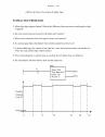
11. Given the following timing diagram, draw the done bits for all four fundamental timer types. Assume all start with an accumulated value of zero, and have a preset of 1.5 seconds.
12. Design ladder logic that allows an RTO to behave like a TON.
13. Design ladder logic that uses normal timers and counters to measure times of 50.0 days.
14. Develop the ladder logic that will turn on an output light (O/1), 15 seconds after switch A (I/1) has been turned on.
15. Develop the ladder logic that will turn on a light (O/1), after switch A (I/1) has been closed 10 times. Push button B (I/2) will reset the counters.
16. Develop a program that will latch on an output B (O/1), 20 seconds after input A (I/1) has been turned on. The timer will continue to cycle up to 20 seconds, and reset itself, until input A has been turned off. After the third time the timer has timed to 20 seconds, the output B will be unlatched.
17. A motor will be connected to a PLC and controlled by two switches. The GO switch will start the motor, and the STOP switch will stop it. If the motor is going, and the GO switch is thrown, this will also stop the motor. If the STOP switch was used to stop the motor, the GO switch must be thrown twice to start the motor. When the motor is running, a light should be turned on (a small lamp will be provided).
18. In dangerous processes it is common to use two palm buttons that require a operator to use both hands to start a process (this keeps hands out of presses, etc.). To develop this there are two inputs that must be turned on within 0.25s of each other before a machine cycle may begin.
0 1 2 3 4 5 6 7sec
input
TON
RTO
TOF
RTF

plc timers - 9.31
19. Design a conveyor control system that follows the design guidelines below.- The conveyor has an optical sensor S1 that detects boxes entering a workcell- There is also an optical sensor S2 that detects boxes leaving the workcell- The boxes enter the workcell on a conveyor controlled by output C1- The boxes exit the workcell on a conveyor controlled by output C2- The controller must keep a running count of boxes using the entry and exit sen-
sors- If there are more than five boxes in the workcell the entry conveyor will stop- If there are no boxes in the workcell the exit conveyor will be turned off- If the entry conveyor has been stopped for more than 30 seconds the count will be
reset to zero, assuming that the boxes in the workcell were scrapped.
20. Write a ladder logic program that does what is described below.- When button A is pushed, a light will flash for 5 seconds.- The flashing light will be on for 0.25 sec and off for 0.75 sec.- If button A has been pushed 5 times the light will not flash until the system is
reset.- The system can be reset by pressing button B
21. Write a program that will turn on a flashing light for the first 15 seconds after a PLC is turned on. The light should flash for half a second on and half a second off.
22. A buffer can hold up to 10 parts. Parts enter the buffer on a conveyor controller by output con-veyor. As parts arrive they trigger an input sensor enter. When a part is removed from the buffer they trigger the exit sensor. Write a program to stop the conveyor when the buffer is full, and restart it when there are fewer than 10 parts in the buffer. As normal the system should also include a start and stop button.
23. What is wrong with the following ladder logic? What will happen if it is used?
24. We are using a pneumatic cylinder in a process. The cylinder can become stuck, and we need to detect this. Proximity sensors are added to both endpoints of the cylinder’s travel to indicate when it has reached the end of motion. If the cylinder takes more than 2 seconds to complete a motion this will indicate a problem. When this occurs the machine should be shut down and a light turned on. Develop ladder logic that will cycle the cylinder in and out repeatedly, and watch for failure.
L
U
A
B
X
Y
X
Y
plc timers - 9.32
9.10 PRACTICE PROBLEM SOLUTIONS
1. edge triggered means the event when a logic signal goes from false to true (positive edge) or from true to false (negative edge).
4. no, but they are essential for retentive timers, and very important for counters.
5. these are limited by the 16 bit number for a range of -32768 to +32767
6. the un underflow bit. This may result in a fault in some PLCs.
7.
8.
first pass
stop
startmotor
motor
L
U
start
motor
stopmotor
input
TON
TOF
delays turning on
delays turning off

plc timers - 9.33
9.
ARTF
Timer T4:0Time Base 0.01Preset 350Accum. 0
A
T4:0/DN
(DN)
(EN)
T4:0.Accum.
0 3 6 10 16 18 20
T4:0/EN
T4:0/TT

plc timers - 9.34
10.
ARTO
Timer T4:0Time Base 1.0Preset 10Accum. 1
A
T4:0 EN
(DN)
(EN)
T4:0 Accum.
0 3 6 9 14 17 19 20
T4:0 TT
T4:0 DN
ATOF
Timer T4:1Time Base .01Preset 50Accum. 0
A
T4:1 EN
(EN)
(DN)
T4:1 Accum.
0 15 45 150 200 225
T4:1 TT
T4:1 DN
plc timers - 9.35
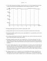
11.
12.
13.
0 1 2 3 4 5 6 7sec
input
TON
RTO
TOF
RTF
RTOTimer T4:0Base 1.0Preset 2
A
ARES T4:0
TONTimer T4:0Base 1.0Preset 3600
A T4:0/DN
CTUCounter C5:0Preset 1200
T4:0/DN
C5:0/DNLight

plc timers - 9.36
14.
15.
I/1
B3/0
B3/0
B3/0
TONT4:0delay 15 sec
T4:0/DN O/01
I/2
I/1
C5:0
CTUC5:0presetR 10
C5:0/DN O/1
RES
plc timers - 9.37
16.
I/1TONT4:0delay 20 s
T4:0/DN O/1
T4:0/DNTONT4:1delay 20 s
L
T4:1/DNCTUC5:0preset 3
C5:0/DN O/1
U
T4:1/DN
plc timers - 9.38
17.
go stop
motor
motor
go CTU
C5:1/DNC5:0
Counter C5:0Preset 2Accumulator 1
CTUCounter C5:1Preset 3Accumulator 1
RES
C5:1RES
C5:1/DNC5:0/DN
stop CTDCounter C5:0Preset 2Accumulator 1
C5:0/DN
CTDCounter C5:1Preset 3Accumulator 1
plc timers - 9.39
18.
TONTimer T4:0Base 0.01Preset 25
TONTimer T4:1Base 0.01Preset 25
left button
right button
T4:1/TT
on
onstopT4:0/TT
plc timers - 9.40
19.
CTUCounter C5:0Preset 6
S1
CTDCounter C5:0Preset 6
S2
C5:0/DNC1
CTUCounter C5:1Preset 1
CTDCounter C5:1Preset 1
C5:1/DNC2
TONTimer T4:0Preset 30s
C5:0/DN
T4:0/DNC5:0RES
C5:1RES
plc timers - 9.41
20.
TONtimer T4:0delay 5s
TONtimer T4:1delay 0.25s
TONtimer T4:2delay 0.75s
CTUcounter C5:0preset 5
RES
A
B
T4:1/TT
C5:0/DN
T4:0/TT T4:2/DN
T4:1/DN
light
T4:0/TT
plc timers - 9.42
21.
22.
23. The normal output ‘Y’ is repeated twice. In this example the value of ‘Y’ would always match ‘B’, and the earlier rung with ‘A’ would have no effect on ‘Y’.
First scanTONT4:0delay 15s
TONT4:1delay 0.5s
TONT4:2delay 0.5s
T4:0/TT
T4:2/DN
T4:1/DN
lightT4:0/TT
start
active
stopactive
CTUcounter C5:0preset 10
enter
CTDcounter C5:0preset 10
exit
active C5:0/DNactive
plc timers - 9.43
24.
9.11 ASSIGNMENT PROBLEMS
1. Draw the timer and counter done bits for the ladder logic below. Assume that the accumulators
GIVE SOLUTION

plc timers - 9.44
of all the timers and counters are reset to begin with.
2. Write a ladder logic program that will count the number of parts in a buffer. As parts arrive they activate input A. As parts leave they will activate input B. If the number of parts is less than 8 then a conveyor motor, output C, will be turned on.
TONTimer T4:0Base 1sPreset 2
RTOTimer T4:1Base 1sPreset 2
TOFTimer T4:2Base 1sPreset 2
CTUCounter C5:0Preset 2
CTDCounter C5:1Preset 2
A
t(sec)
A
0 5 10 15 20
T4:0/DN
T4:1/DN
T4:2/DN
C5:0/DN
C5:1/DN
Acc. 0
Acc. 0

plc timers - 9.45
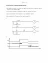
3. Explain what would happen in the following program when A is on or off.
4. Write a simple program that will use one timer to flash a light. The light should be on for 1.0 seconds and off for 0.5 seconds. Do not include start or stop buttons.
5. We are developing a safety system (using a PLC-5) for a large industrial press. The press is activated by turning on the compressor power relay (R, connected to O:013/05). After R has been on for 30 seconds the press can be activated to move (P connected to O:013/06). The delay is needed for pressure to build up. After the press has been activated (with P) the system must be shut down (R and P off), and then the cycle may begin again. For safety, there is a sen-sor that detects when a worker is inside the press (S, connected to I:011/02), which must be off before the press can be activated. There is also a button that must be pushed 5 times (B, con-nected to I:011/01) before the press cycle can begin. If at any time the worker enters the press (and S becomes active) the press will be shut down (P and R turned off). Develop the ladder logic. State all assumptions, and show all work.
6. Write a program that only uses one timer. When an input A is turned on a light will be on for 10 seconds. After that it will be off for two seconds, and then again on for 5 seconds. After that the light will not turn on again until the input A is turned off.
7. A new printing station will add a logo to parts as they travel along an assembly line. When a part arrives a ‘part’ sensor will detect it. After this the ‘clamp’ output is turned on for 10 sec-onds to hold the part during the operation. For the first 2 seconds the part is being held a ‘spray’ output will be turned on to apply the thermoset ink. For the last 8 seconds a ‘heat’ out-put will be turned on to cure the ink. After this the part is released and allowed to continue along the line. Write the ladder logic for this process.
8. Write a ladder logic program. that will turn on an output Q five seconds after an input A is turned on. If input B is on the delay will be eight seconds. YOU MAY ONLY USE ONE TIMER.
MCR
TONT4:05s
MCR
A